

Page 1
Revision
Date
Author
Change Description
1
05/03/2012
F. Perkins
Initial issue
2
01/09/2015
R. Willett
Reformatted to comply with new Murata V.I.
RFM products are now
DN-24 Series
2.4 GHz
User Guide
Revision History
Murata products.
Serial Modems
©2009-2015 by Murata Electronics N.A., Inc.
DN24G/GI Series User Guide Rev. 2.0 01-09-15 Page 1 of 44 www.murata.com
Page 2

Important Regulatory Information
RFM Product FCC ID: HSW-DNT24
IC 4492A-DNT24
Note: This equipment has been tested and found to comply with the limits for a Class B digital
device, pursuant to Part 15 of the FCC Rules. These limits are designed to provide reasonable
protection against harmful interference in a residential installation. This equip m ent generates,
uses, and can radiate radio frequency energy and, if not installed and used in accordance with the
instructions, may cause harmful interference to radio communications. If this equipment does
cause harmful interference to radio or te levision reception, which can be determine d by turning
the equipment off and on, the user is encouraged to try to correct the interference by one or more
of the following measures:
1) Re-orientate or relocate the receiving antenna,
2) Increase the separation between the equipment and the radiator,
3) Connect the equipment into an outlet on a circuit different from that to which the receiver is connected,
4) Consult the dealer or an experienced radio/TV technician for help.
FCC Antenna Gain Restriction:
The DN-24 series 2.4 GHz serial modems have been designed to operate with any dipole antenna of up
to 12 dBi of gain, any corner reflector antenna of up to 14 dBi gain, any patch antenna of up to 12 dBi
gain. The antenna(s) used for this transmitter must be installed to provide a separation distance of at
least 20 cm from all persons and must not be co-located or operating in conjunction with any other
antenna or transmitter.
IC RSS-210 Detachable Antenna Gain Restriction:
This radio transmitter, IC 4492A-DNT24, has been approved by the Industry Canada to operate with the
antenna types listed below with the maximu m per miss i ble ga in and the requ ir ed a nten na imp eda nc e for
each antenna type indicated. Antenna types not included in this list, having a gain greater than the
maximum gain indicated for that type, are strictly prohibited for use with this device.
Le présent émetteur radio IC 4492A-DNT24 a été approuvé par Industrie Canada pour fonctionner
avec les types d'antenne énumérés ci-dessous et ayant un gain admissible maximal et l'impédance
requise pour chaque type d'antenne. Les types d'antenne non inclus dans cette liste, ou dont le gain est
supérieur au gain maximal indiqué, sont strictement interdits pour l'exploitation de l'émetteur.
Type Model Number Gain Impedance
Omnidirectional OD12-2400 12 dBi 50 ohm
Corner SCR14-2400CT 14 dBi 50 ohm
Patch PA2412 12 dBi 50 ohm
Dipole S181AH-2450S 2 dBi 50 ohm
©2009-2015 by Murata Electronics N.A., Inc.
DN24G/GI Series User Guide Rev. 2.0 01-09-15 Page 2 of 44 www.murata.com
Page 3

Under Industry Canada regulations, this radio transmitter may only operate using an antenna of a type
and maximum (or lesser) gain approved for the transmitter by Industry Canada. To reduce potential radio
interference to other users, the antenna type and its gain should be so chosen that the equivalent
isotropically radiated power (e.i.r.p.) is not more than that permitted for successful communication.
Conformément à la réglementation d'Industrie Canada, le présent émetteur radio peut fonctionner
avec une antenne d'un type et d'un gain maximal (ou inférieur) approuvé pour l'émetteur par Industrie
Canada. Dans le but de réduire les risques de brouillage radioélectrique à l'intention des autres
utilisateurs, il faut choisir le type d'antenne et son gain de sorte que la puissance isotrope rayonnée
équivalente (p.i.r.e.) ne dépasse pas l'intensité nécessaire à l'établissement d'une communication
satisfaisante.
This device complies with Industry Canada license-exempt RSS standard(s). Operation is subject to the
following two conditions: (1) this device may not cause interference, and (2) this device must accept any
interference, including interference that may cause undesired operation of the device.
Le présent appareil est conforme aux CNR d'Industrie Canada applicables aux appareils radio exempts
de licence. L'exploitation est autorisée aux deux conditions suivantes : (1) l'appareil ne doit pas produire
de brouillage, et (2) l'utilisateur de l'appareil doit accepter tout brouillage radioélectrique subi, même si le
brouillage est susceptible d'en compromettre le fonctionnement.
Changes or modifications to a DN-24 series serial modem not expressly approved by Murata Electronics
N.A., Inc. may void the user’s authority to operate the module.
©2009-2015 by Murata Electronics N.A., Inc.
DN24G/GI Series User Guide Rev. 2.0 01-09-15 Page 3 of 44 www.murata.com
Page 4

Table of Contents
1.0 DN-24 Series 2.4 GHz Serial Modems ............................................................................................... 5
2.0 DN-24 Systems ................................................................................................................................... 5
2.1 Point-to-Point System s..................................................................................................................... 5
2.2 Point-to-Multipoint Systems ............................................................................................................. 6
2.3 Store-and-Forward Systems ............................................................................................................ 7
2.4 DN-24 Product Descript ion s ................................................................................................................ 8
3.0 Specifications ...................................................................................................................................... 9
3.1 Absolute Maximum Ratings ................................................................................................................. 9
3.2 System Specifications ......................................................................................................................... 9
3.3 LED Indicators ..................................................................................................................................... 9
4.0 Installation ......................................................................................................................................... 10
4.1 Mounting and Location ...................................................................................................................... 10
4.2 Attaching the Antenna ....................................................................................................................... 11
4.3 DN-24G Connector Details ................................................................................................................ 11
4.4 DN-24GI Connector Details ............................................................................................................... 12
4.5 Basic DN-24 Point-to-Point System Setup ........................................................................................ 12
5.0 DN-24 Technical Reference .............................................................................................................. 13
5.1 RF Channel Access ........................................................................................................................... 13
5.2 DN-24 Addressing ............................................................................................................................. 13
5.3 Network Linking and Slot Registration .............................................................................................. 14
5.4 Transparent and Protocol-formatted Serial Data .............................................................................. 14
6.0 DN-24 System Configuration ............................................................................................................. 15
6.1 Configuration Parameters .............................................................................................................. 15
6.2 Configuring a Basic Point-to-Point System .................................................................................... 15
6.3 Configuring a Basic Point-to-Multipoint System ............................................................................. 15
6.4 C onf igur ing a Cust omized Point-to-Point or Point-to-Mult ipo int System ....................................... 16
6.5 Configuring a Store-and-Forward System ..................................................................................... 18
6.6 Slot Buffer Sizes, Number of Slots, Messages per Hop and Hop Duration ................................... 18
6.7 Configuring the Serial Port ............................................................................................................. 21
7.0 DN-24 Protocol-form atted Messages ................................................................................................ 21
7.1 Protocol Formats ............................................................................................................................ 21
7.2 Message Types .............................................................................................................................. 21
7.3 Message Format Details ................................................................................................................ 22
7.4 Configuration Parameter Registers ................................................................................................ 28
7.4.1 Bank 0x00 - Transc eiver S etup .................................................................................................. 28
7.4.2 Bank 0x01 - System Settings ...................................................................................................... 30
7.4.3 Bank 0x02 - Status Param et ers .................................................................................................. 32
7.4.4 Bank 0x03 - Serial Settings ........................................................................................................ 33
7.4.5 Bank 0x04 - Host Protocol Sett ings ............................................................................................ 34
7.4.6 Bank 0x0FF - Special Functions ................................................................................................. 35
7.5 Protocol-formatted Message Example........................................................................................ 35
8.0 Utility Program ................................................................................................................................... 36
8.1 Serial Communication and Radio Configuration ............................................................................ 38
9.0 Warranty ............................................................................................................................................ 44
©2009-2015 by Murata Electronics N.A., Inc.
DN24G/GI Series User Guide Rev. 2.0 01-09-15 Page 4 of 44 www.murata.com
Page 5

1.0 DN-24 Series 2.4 GHz Serial Modems
The DN-24 series 2.4 GHz serial modems provide a low cost, ready-to-use solution for robust wireless
data communications in the 2.4 GHz ISM band. There are currently two products in the DN-24 series, the
DN-24G and the DN-24GI. The DN-24G provides an RS-232C serial interface with optional hardware flow
control. The DN-24GI offers a selectable 3-wire RS-232C interface or a two-wire, mult i-drop RS-485
interface. All DN-24 series modems are based on Murata’s DNT24 frequency hopping spread spectrum
(FHSS) transceiver, and can communicate with other DNT24-based modems and sensor nodes, as well
as customer developed products. DN-24 series modems are suppl ied wit h a dipo le ante nna and a wallplug power supply. A DN-24 transmits data at 250 kbps. The RF output power can be set up to 100 mW
EIRP using the supplied 2 dBi dipole antenna. Optional high-gain directional and omni-directional
antennas are available to extend operating range where local regulations allow it. DN-24 series modems
are well suited for sensor and data networks carrying moderate traffic that need robust communications in
locations with non-ideal RF propagation and/or where RF interference or noise are present.
Key Features of the DN-24 Series 2.4 GHz Serial Modems include:
- 2.4 GHz wireless connectivity for RS-232C or RS-485 serial interfaces
- Optional 128-Bit AES Encryption
- Point-to-point, Po int-to-multipoint, Peer-to-peer and
Store & Forward Capabilities
- Frequency Hopping Spread Spectrum Transceiver
- 250 kbps RF Data Rate
- Transmitter Power up to 100 mW EIRP with 2 dBi Antenna
- FCC, Canadian IC Certified and CE Marked for Unlicensed Operation
2.0 DN-24 Systems
DN-24 wireless serial modems can be configured to operate in one of three modes - base, remote or
router. A base controls a DN-24 system, and interfaces to an application host such as a PC. A remote
simply functions to transmit or receive data. A router alternates between functioning as a remote on one
hop and a network base on the next hop. When acting as a remote, the router stores messages it
receives from its parent, and then repeats the messages to its child rad ios when ac ting as a network
base. Likewise, a router will store messages received from its child radios when acting as a base, and
repeat them to its parent when acting as a remote. Any message addressed directly to a router is
processed by the router rather than being repeated.
2.1 Point-to-Point Systems
A DN-24 system contains at least one network. The simplest DN-24 topology is a point-to-point system,
as shown in Figure 2.1.1. This system consists of a base and one remote forming a single network. Pointto-point systems are often used to replace wired serial connections.
©2009-2015 by Murata Electronics N.A., Inc.
DN24G/GI Series User Guide Rev. 2.0 01-09-15 Page 5 of 44 www.murata.com
Page 6
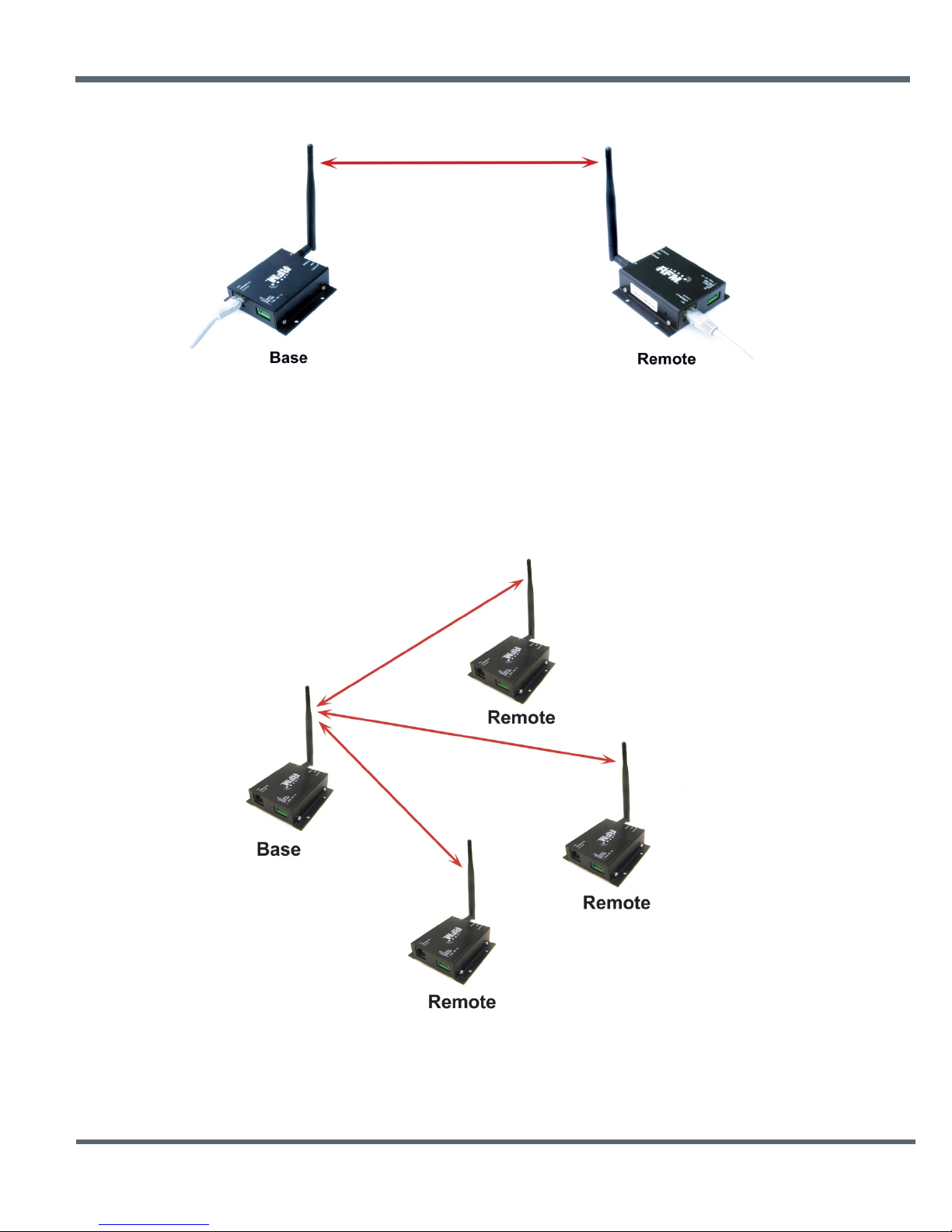
Figure 2.1.1
2.2 Point-to-Multipoint Systems
Figure 2.2.1 shows the topology of a point-to-multipoint (star) system, which consists of a base and more
than one remote in a single network. Point-to-multipoint systems are typically used for data, sensor and
alarm systems. While most traffic in a point-to-multipoint system is between the base and the remotes,
DN-24 technology also allows for peer-to-peer communication from one remote to another.
©2009-2015 by Murata Electronics N.A., Inc.
DN24G/GI Series User Guide Rev. 2.0 01-09-15 Page 6 of 44 www.murata.com
Figure 2.2.1
Page 7
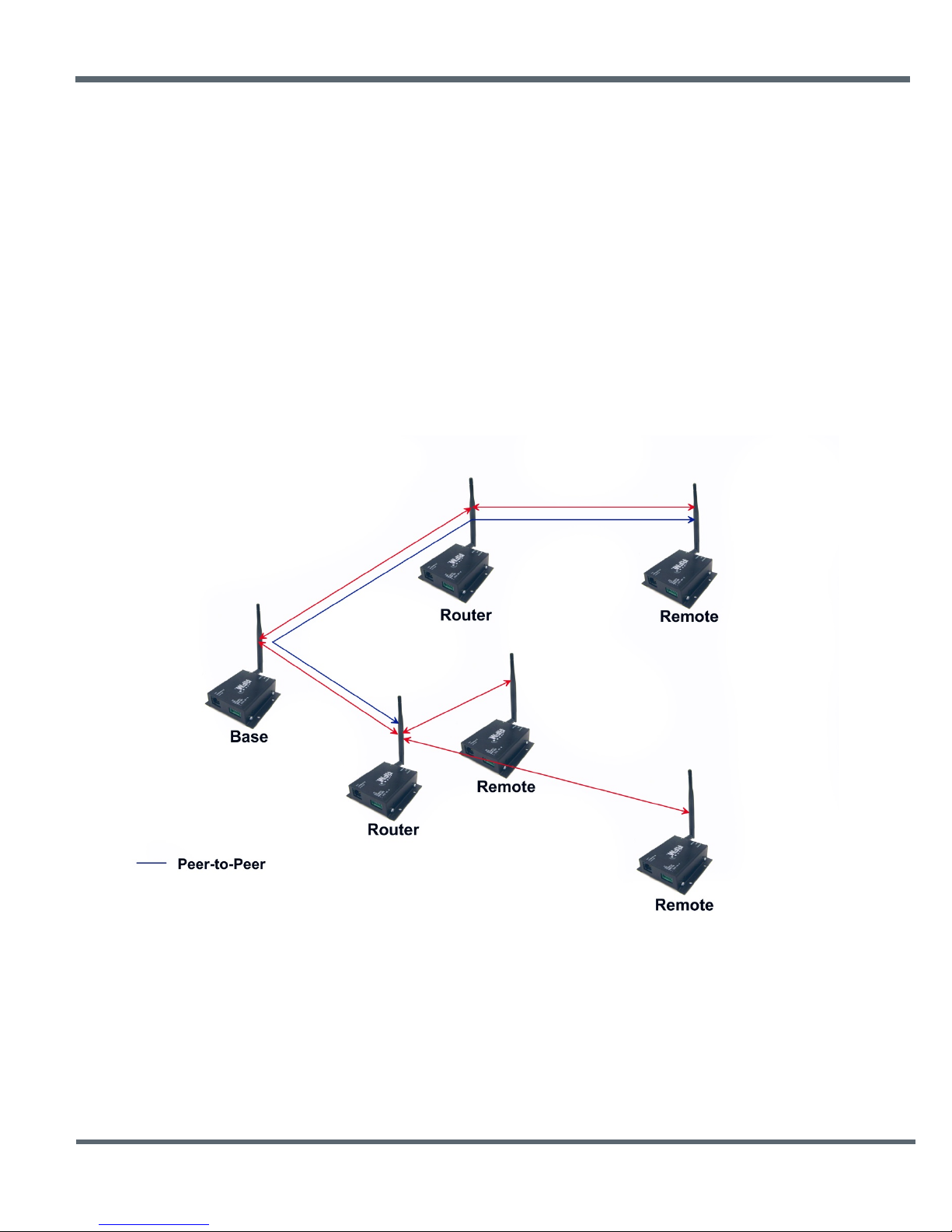
Figure 2.3.1
2.3 Store-and-Forward Systems
Figure 2.3.1 shows the topology of a store-and-forward system, which consists of a base, one or more
routers, one or more remotes, and two or more networks. Networks in a store-and-forward system form
around the base and each router. The base and the routers are referred to as the parents of the networks
they form. The rest of the radios in each network are referred to as child radios. Note that a router is a
child of the base or another router while being the parent of its own network. Each network parent
transmits beacons to allow child radios to synchronize with its hopping pattern and join its network.
Different frequency hopping patterns are used by the parent radios in a system, minimizing interference
between networks.
Store-and-forward systems are used to cover larger areas than is possible with point-to-point or point-tomultipoint systems. The trade-off in store-and-forward systems is longer delivery times due to receiving
and retransmitting a message several times. Store-and-forward systems are especially useful in
applications such as agriculture where data is only collected periodically.
©2009-2015 by Murata Electronics N.A., Inc.
DN24G/GI Series User Guide Rev. 2.0 01-09-15 Page 7 of 44 www.murata.com
Page 8
2.4 DN-24 Product Descriptions
There are currently two products in the DN-24 series, the DN-24G and the DN-24GI. The DN-24G
provides an RS-232C serial interface. The DN-24GI offers a selectable RS-232C interface or a two-wire,
multi-drop RS-485 int er f ac e. DN-24 series modems are based on Murata’s DNT24 frequency hopping
spread spectrum (FHSS) transceiver, and can communicate with other DNT24-based modems and
sensor nodes, as well as customer developed products.
DN-24 series modems are supplied with a reverse SMA dipole antenna and a universal wall-plug power
supply. DN-24 modems transmit data at 250 kbps. The transmitter output power can be set up to 100 mW
EIRP using the supplied 2 dBi dipole antenna.
Optional high-gain directional and omni-directional
antennas are available from Murata to extend operating range where allowed by local regulations.
DN-24 series modems are well-suited for sensor and data networks carrying moderate traffic that need
robust communications in loc atio ns with non-ideal RF propagation and/or where RF interference or noise
are present.
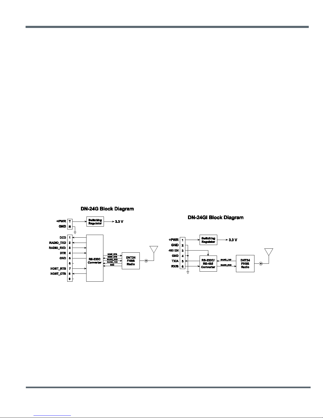
As shown in Figures 2.4.1 and 2.4.2, serial data to/from a DN-24G is routed through an RS232C signal
converter. In the case of a DN-24GI, serial data is routed through an RS-232C/RS-485 signal converter.
When terminal 3 is left unconnected on the DN-24GI, serial communication is 3-wire RS-232C. When
terminal 3 is connected to terminal 2 or 4, serial communication is 2-wire, multi-drop capable RS-485.
Terminal 3 has no function in a DN-24G.
The switching regulator used in all DN-24 modems supports a
wide voltage range on the DC power input, from 9 to 24 Vdc.
Figure 2.4.1 Figure 2.4.2
©2009-2015 by Murata Electronics N.A., Inc.
DN24G/GI Series User Guide Rev. 2.0 01-09-15 Page 8 of 44 www.murata.com
Page 9
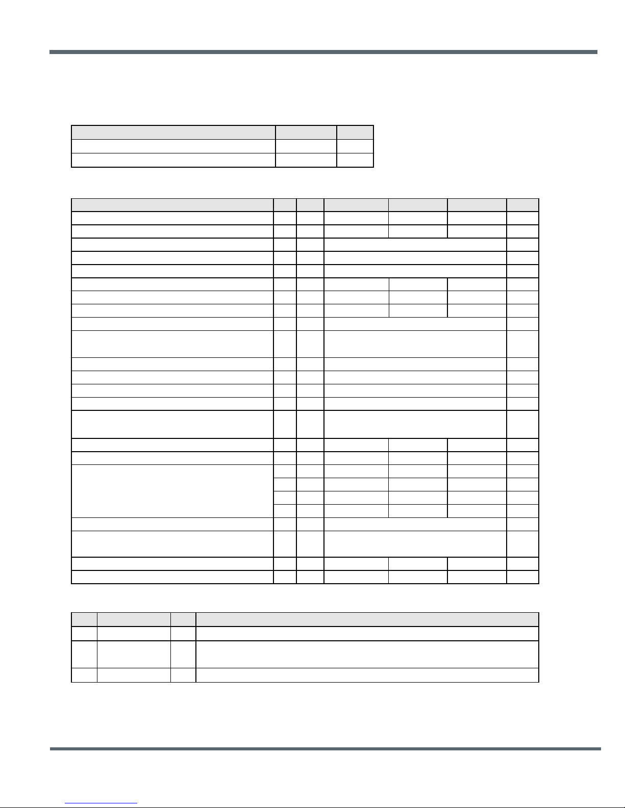
o
Characteristic
Sym
Notes
Minimum
Typical
Maximum
Units
Operating Frequency Range
2406
2475
MHz
Hop Dwell Time
8
100
ms
Number of RF Channels
15 or 24
dBm
EIRP RF Output Power Level, 2 dBi Antenna
100
mW
Optimum Antenna Impedance
50
Ω
RF Connection
RSMA Coaxial Connector
Ad Hoc TDMA
DN-24G RS-232C
9-pin connector, hardware flow control optional
DN-24GI RS-232C Configuration
3-wire, no hardware flow control required
DN-24GI RS-485 Configuration
2-wire, multi-drop capable
V
mA
Base, Continuous Data Stream
129
mA
Remote, linked, No Data
34
mA
Remote, Continuous Data Stream
44
mA
Nominal Dimensions
3.3 x 3.2 x 1 inches (84.6 x 82.0 x 25.4 mm)
o
POWER
O
3.0 Specifications
3.1 Absolute Maximum Ratings
Rating Value Units
Power Supply Input Voltage Range -0.5 to +24 V
Non-Operating Ambient Temperature Range -40 to +85
3.2 System Specifications
C
Modulation
RF Data Transmission Rate
Receiver Sensitivity @ 10-5 BER
Network Topologies
Access Scheme
Serial Port Baud Rates
Power Supply Voltage Range VCC
Peak Transmit Mode Current
Average Receive Mode Current:
Mounting
Operating Temperature Range
Operating Relative Humidity Range, Non-condensing
3.3 LED Indicators
Ref Name I/O Description
1
2
3
ACTIVITY O
LINK O
Left-most LED on the front of the unit, amber, indicates RF communications activity.
Middle LED on the front of the unit, red. On a base, this LED indicates one or more remotes
are linked to it. On a remote, this LED indicates it is linked to the base.
Right-most LED on the front of the unit, green, indicates the unit is powered up.
FSK
250 kbps
Point-to-Point, Point-to-Multipoint,
Peer-to-Peer and Store & Forward
1.2, 2.4, 4.8, 9.6, 14.4, 19.2, 28.8,
38.4, 57.6, 115.2, 230.4, 250.0
+9 +24
190
Left and Right Flanges, Two Pre-drilled Holes
-40 85
10 90 %
-100
in Each Flange
kbps
C
©2009-2015 by Murata Electronics N.A., Inc.
DN24G/GI Series User Guide Rev. 2.0 01-09-15 Page 9 of 44 www.murata.com
Page 10
4.0 Installation
4.1 Mounting and Location
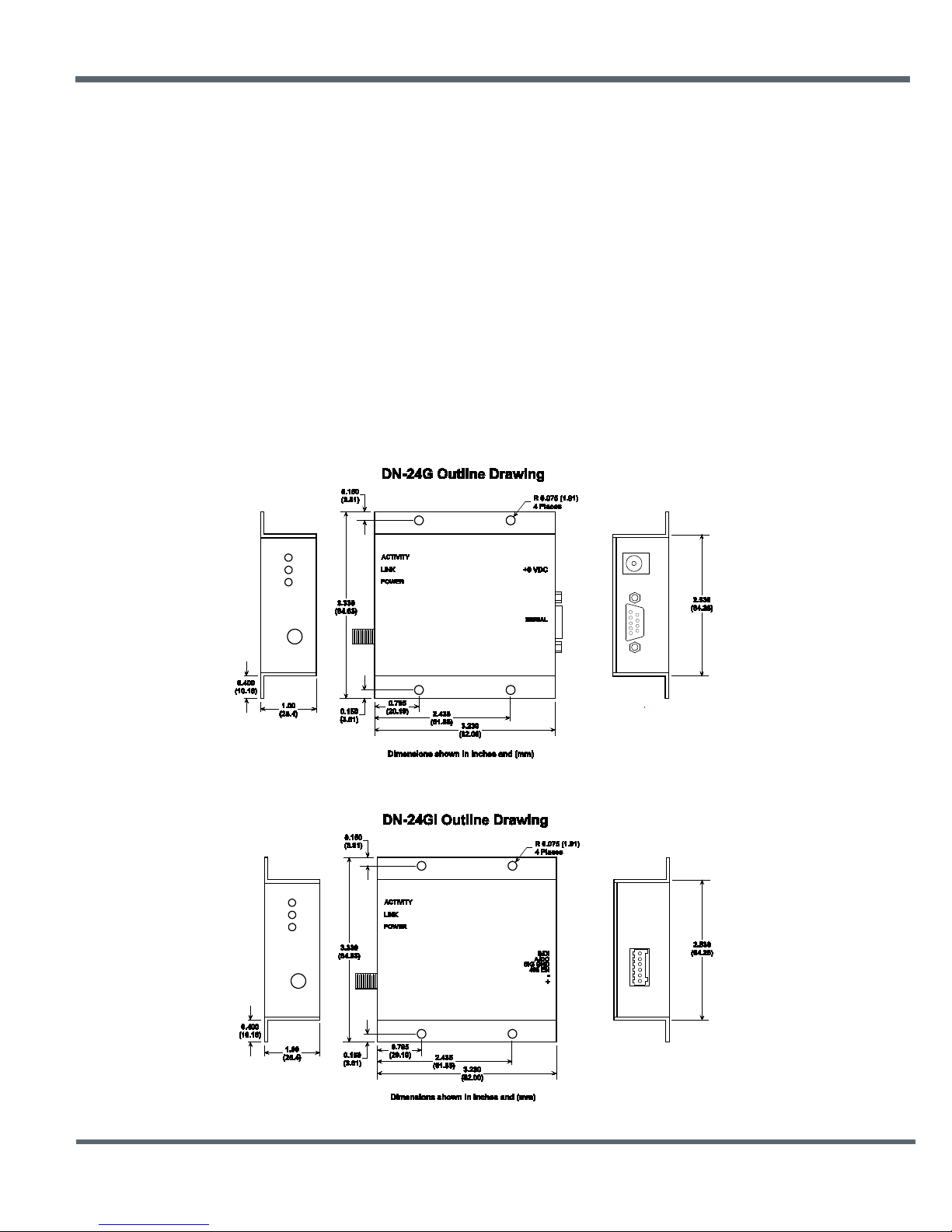
The DN-24G and DN-24GI case outline drawings are shown in Figures 4.1.1 and 4.1.2. The supplied
antenna is hinged, allowing it to be set vertically with the case mounted either horizontally or vertically.
The DN-24 case is designed for indoor use. It must be installed in a weather proof enclosure when used
outdoors, such as a NEMA 4X enclosure. The enclosure must be made of plastic or other materials with
low RF attenuation to avoid compromising antenna performance. Metal enclosures are not suitable for
use with internal antennas as they will block antenna radiation and reception.
DN-24 modems should be mounted at least six feet above the floor (ground) to achieve good
communication reliability in a typical office or retail location. To achieve maximum range and reliability,
especially in industrial locations, the DN-24 should be mounted as high as practical. Murata offers a
number of high gain antennas that can be used to further extend the DN-24’s range. The use of these
antennas is not allowed in all geographical regions; contact RFM’s technical service department for
additional details.
©2009-2015 by Murata Electronics N.A., Inc.
DN24G/GI Series User Guide Rev. 2.0 01-09-15 Page 10 of 44 www.murata.com
Figure 4.1.1
Page 11
+PWR
I
GND
-
DTR
I
GND
-
-
-
HOST_RTS
I
Figure 4.1.2
4.2 Attaching the Antenna
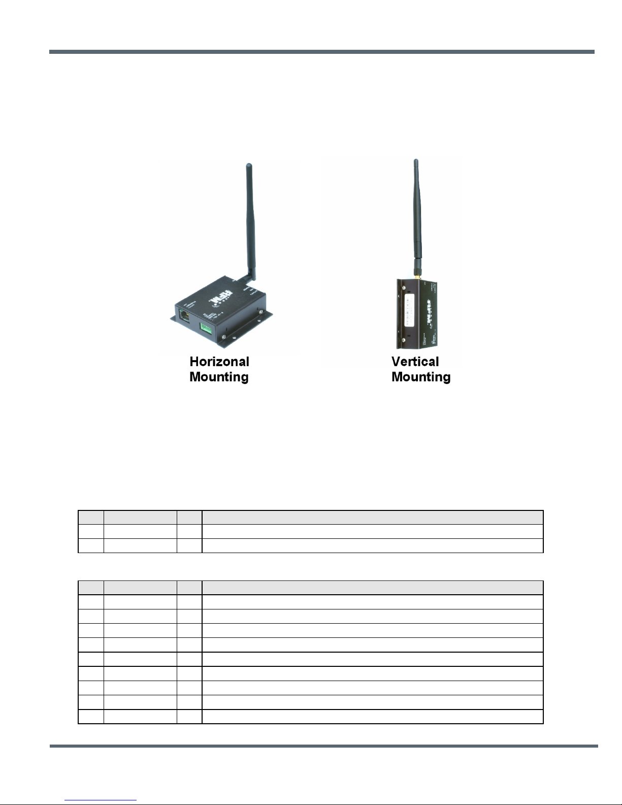
The antenna (or antenna cable) is attached by screwing the antenna onto the antenna connector. The
supplied antennas are hinged, allowing them to be set vertically with the case mounted either horizontally
or vertically as shown in Figure 4.2.1.
Figure 4.2.1
4.3 DN-24G Connector Details
A coaxial power connector is provided on the DN-24G for the DC power input, and a nine-pin male
connector is provided for the RS-232C signal connection. Strai ght throu gh w iri ng should be used between
the DN-24G and its host. The DN-24G serial interface can be used with or without hardware flow control.
DN-24G Power Connector Description
Ref Name I/O Description
T
R
The center coaxial conductor (tip) is the positive power supply input, +9 to +24 V.
The outer coaxial conductor (ring) is the DC power ground.
DN-24G Serial Port Connector Description
Pin Name I/O Description
1
2
3
4
5
6
7
8
9
DCD O
RADIO_TXD O
RADIO_RXD I
HOST_CTS O
- -
This pin is an output indicating the modem is linked to the radio network.
This pin is the modem serial data output.
This pin is the modem serial data input
This pin is the data terminal ready input from the modem’s host.
This pin is signal ground
No connection
This pin is the request to send input from the modem’s host
This pin is the clear to send output from the modem.
No connection
©2009-2015 by Murata Electronics N.A., Inc.
DN24G/GI Series User Guide Rev. 2.0 01-09-15 Page 11 of 44 www.murata.com
Page 12
+PWR
I
GND
-
GND
-
4.4 DN-24GI Connector Details
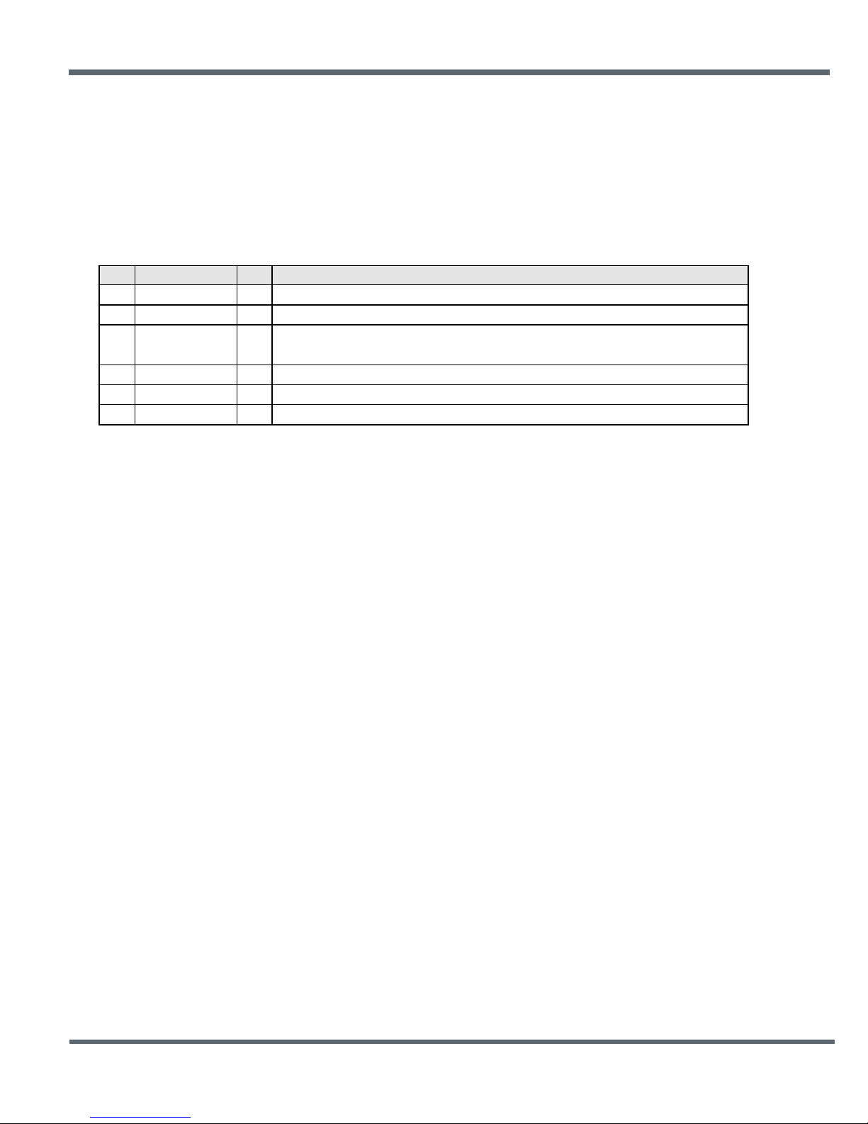
A terminal strip is provided on the DN-24GI for power and data signal connection. For RS-232C
operation, terminal 3 should be left unconnected and straight throu gh wir ing should be used between the
DN-24GI and its host. RS-232C operation is 3-wire; no hardware hand-shaking signals are provided. If
the host application requires hardware handshaking, CTS-RTS and DTR-DCD loopbacks should be
installed on the connector that plugs into the host.
DN-24GI DC Power/Serial Port Termi nal Blo ck Des c rip t ion
Pin Name I/O Description
1
2
3
4
5
6
485 EN I
TX/A O
RX/B I
For RS-485 operation, terminal 3 should be connected to terminal 2 or 4. RS-485 operation is 2-wire, and
is compatible with multi-drop RS-485 install ations . The primary application for the DN-24GI is in RS-485
applications. In this case, the RS-232C mode provides a convenient way to configure the modem prior to
installing it in an RS-485 network.
4.5 Basic DN-24 Point-to-Point System Setup
A basic DN-24 point-to-point system is suitable for many serial data applications. The default
configuration of a DN-24 is a remote with the serial port configured for transparent operation at
9.6 kbps, 8N1. To set up a basic point-to-point system:
1. Configure one of the modules as a base by setting the DeviceMode parameter in Bank 0 to 0x01.
2. Set the MemorySave parameter in Bank 0xFF to 0xD2, which will save the DeviceMode
parameter to EEPROM. Then reset the module, which enables base operation.
3. All other parameters may be left at their default values.
Murata provides a setup utility program called DNCONFIG.exe that configures a DN-24 modem as a base
or a remote, and optionally sets the serial port to a baud rate other than the 9.6 kbps default.
DNCONFIG.exe can be simply copied onto a PC (Windows XP or later operating system) and run. Select
Base in the Mode drop-down box and click Configure and Reset. Note that a DN-24GI must be in RS-
232C mode to use this utility. Another utility program, DNTDEMO.exe, allows full control of all
configuration parameters relevant to the operation of a DN-24 based system. Use this program to set up
advanced DN-24 systems, such as a store-and-forward system. DNTDEMO is discussed in Section 8.0 of
this user guide.
This terminal is the positive power supply input, +9 to +24 V.
This terminal is a power supply and signal ground.
When this terminal is unconnected, serial operation is RS-232C. When this terminal
is grounded to terminal 2 or 4, serial operation is RS-485.
This terminal is a power supply and signal ground.
This terminal transmits serial data to the host, RS-232C TxD or RS-485 A signal.
This terminal receives serial data from the host, RS-232C RxD or RS-485 B signal.
©2009-2015 by Murata Electronics N.A., Inc.
DN24G/GI Series User Guide Rev. 2.0 01-09-15 Page 12 of 44 www.murata.com
Page 13
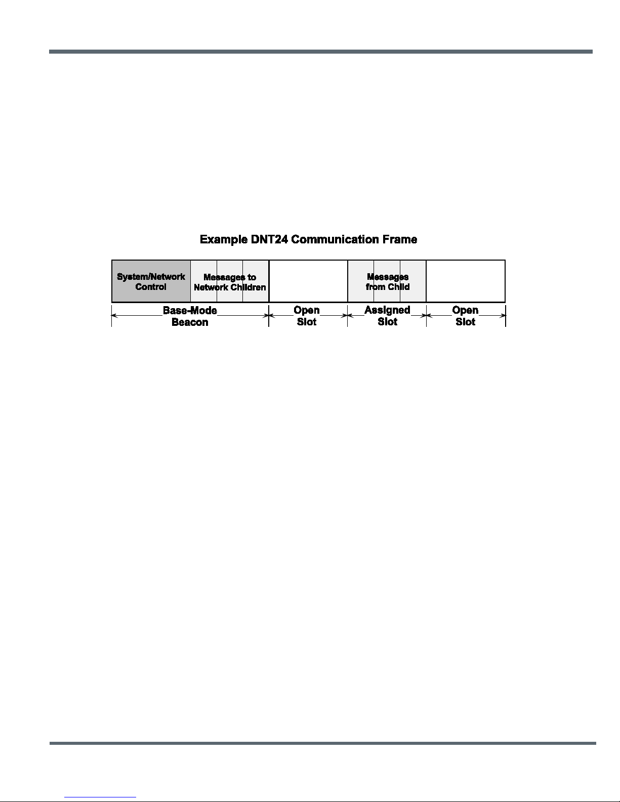
Figure 5.1.1
5.0 DN-24 Technical Reference
5.1 DN-24 RF Channel Access
The time a DN-24 network stays on each frequency in its hopping pattern is called the hop duration or
dwell time, which can be configured from 8 to 100 ms. Radio communication during each dwell is
organized as a time division multiple access (TDMA) frame. A DN-24 frame begins with a base-mode
beacon, followed by 1 to 8 time slots used by the network children to transmit to their parent, as shown in
Figure 5.1.1. A base-mode beacon can include up to 8 messages addressed to one or more child radios.
The number of slots is chosen accommodate the number of children that need to send messages each
hop.
Each beacon includes the status of all slots - either registered (assigned) or open. When a child radio has
information to transmit to its parent, it randomly selects one of the open slots and transmits all or the first
part of its data. If the parent successfully receives the transmission, it includes the child’s MAC address in
the next beacon. This signals the child radio that the slot is temporarily registered to it, allowing the child
to efficiently stream any remaining data to the base hop-by-hop until it is all sent.
If a child radio does not see its address in the next beacon following its transmission, it again randomly
selects an open slot and retransmits its data. During times when there are no open slots, a child radio
keeps its data queued and continues to look for an open slot in each beacon until at least one slot
becomes available. The access method the DN-24 uses is referred to as Ad Hoc TDMA.
5.2 DN-24 Addressing
Each DN-24 has a unique MAC address. The MAC address can be read or bar-code scanned from the
label on the side of each radio. A DN-24 radio in any mode (base/router/remote) can be addressed using
its MAC address. A DN-24 base can be addressed using either its MAC address or address 0x000000. A
DN-24 can send a message to all other DN-24’s in its system by using the broadcast address 0xFFFFFF.
The base and all routers (parents) hold base-mode network IDs, which are transmitted in every beacon.
All routers and remotes hold parent network IDs and optionally alternate parent network IDs to compare
against the base-mode network IDs in the beacons they receive. A child router or remote is allowed to
join a parent if the child’s parent network ID or alternate parent network ID matches the parent’s base-
mode network ID, or with an y parent when its parent network ID is set to 0xFF (wildcard).
In a point-to-point or point-to-multipoint system, the default base-mode network ID of 0xFF (wildcard) can
be used. In a store-and-forward system, however, the base-mode network IDs of all routers must be set
to different values between 0x00 to 0x3F. If the base-mode network ID of 0x00 is assigned to a router, the
©2009-2015 by Murata Electronics N.A., Inc.
DN24G/GI Series User Guide Rev. 2.0 01-09-15 Page 13 of 44 www.murata.com
Page 14

base must be assigned an unused base-mode network ID between 0x01 and 0x3F. Leaving all parent
network IDs in a store-and-forward system set to the default value of 0xFF allows networks to
automatically form, and self-repair if a parent router fails. Enabling the alternate parent network ID also
provides self-repairing message routing.
All DN-24 radios hold a system ID that can be used to distinguish systems that physically overlap. In a
DN-24 system, the system ID must be different from those used by overlapping systems to provide
message filtering. Also, using different base-mode network IDs for all networks in overlapping systems
helps reduce hopping pattern collisions.
The store-and-forward path between the base and any other radio in a system can be determined by
reading the radio’s ParentMacAddress parameter. If this address is not the base, then reading the Parent-
MacAddress parameter of its parent, grandparent, etc., in succession reveals the complete path to the
base. Path determination is useful in optimizing and troubleshooting systems during commissioning and
maintenance.
5.3 Network Linking and Slot Registration
When first turned on, a DN-24 router or remote rapidly scans all frequency channels in its operating band
to acquire synchronization and link to a parent based on a system ID match plus a base-mode network ID
to parent network ID/alternate parent network ID match (or by using a wildcard (0xFF) parent network ID).
In addition to the slot status and the MAC addresses of child radios holding slot registrations, each basemode beacon includes one of a number of cycled control parameters. The cycled parameters are
collected by child radios, allowing them to register with a parent, and to later follow any control parameter
changes. When a router or remote has collected a full set of cycled parameters, it can issue an optional
initial heartbeat message and then optional periodic heartbeat messages which allows an application to
maintain the status of all routers and remotes in its DN-24 system.
When a router/remote has data to send to its parent, it picks an open slot at random and transmits. It then
looks for its MAC address in the next beacon. If its MAC address is present in the beacon, it is temporarily
registered to the slot and continues to use it until all current data is sent, or its MAC address drops off the
beacon.
5.4 Transparent and Protocol-formatted Serial Data
A DN-24 remote can directly input and output data bytes and data strings on its serial port. This is
referred to as transparent serial port operation. In a point-to-point system or in multi-point systems when
broadcast addressing is used, the base can also be configured for transparent serial port operation.
In all other cases, serial data will be protocol formatted:
- configuration commands and replies
Protocol-formatted messages are discussed in detail in Section 7 of this manual. Briefly, protocolformatted messages include a start-of-messages character, message length and message type
information, the destination address of the message, and the message payload.
- announcement messages including heartbeats
©2009-2015 by Murata Electronics N.A., Inc.
DN24G/GI Series User Guide Rev. 2.0 01-09-15 Page 14 of 44 www.murata.com
Page 15

Transparent data is routed using a remote transparent destinati on addres s . In a remote, this address
defaults to the base, 0x000000, and in the base this address defaults to broadcast, 0xFFFFFF. These
defaults can be overridden with specific radio addresses. For example, it is possible to set up transparent
peer-to-peer routing between two remotes in a point-to-multipoint or store-and-forward system by loading
specific MAC addresses in each radio’s remote transparent destination address.
6.0 DN-24 System Configuration
DN-24 radios feature an extensive set of configuration options that allows them to be adapted to a wide
range of applications. Configuration defaults have been carefully selected to minimize the configuration
effort for most applications, while providing the ability to individually adjust the configuration of each radio
to achieve highly optimized system operation.
6.1 Configuration Parameters
The configuration of a DN-24 is controlled by a set of parameters (registers). Parameters that address a
particular aspect of operation are grouped into a bank. All parameters can be accessed through a
module’s serial port and over the radio link. Most parameters are read/write. Read-only parameters
include fixed values such a MAC addresses, firmware version numbers and parameters that are
dynamically adjusted during system operation such as link status. Write-only parameters include security
keys and certain action triggers such as reset. Incorrectly configuring certain parameters can disable a
module’s radio link, but the configuration can always be corrected through the serial port. The
organization of the parameter register banks and the details of each parameter are covered in Section 7.4
of this guide. Sections 7.4.1 through 7.4.6 discuss which parameters apply to various aspects of
configuring a DN-24 system, network or application interface.
6.2 Configuring a Basic Point-to-Point System
A basic DN-24 point-to-point system is suitable for many serial data applications. The default
configuration of a DN-24 is a remote with the serial port configured for transparent operation at
9.6 kbps, 8N1. To configure a basic point-to-point system:
4. Configure one of the modules as a base by setting the DeviceMode parameter in Bank 0 to 0x01.
5. Set the MemorySave parameter in Bank 0xFF to 0xD2, which will save the DeviceMode
parameter to EEPROM and reset the module, enabling base operation.
6. All other parameters may be left at their default values.
6.3 Configuring a Basic Point-to-Multipoint Point System
A basic DN-24 point-to-multipoint point systems is suitable for many serial data applications where
multiple remotes are used. The default configuration of a DN-24 is a remote with the serial port
configured for transparent operation at 9.6 kbps, 8N1. To configure a basic point-to-multipoint system:
1. Configure one of the modules as a base by setting the DeviceMode parameter in Bank 0 to 0x01.
2. If the host application driving the base will individually communicate each remote, set the
ProtocolMode parameter in Bank 4 of the base to 0x01. This step is not required if messages
from the base to the remotes will always be broadcast and/or the base does not need to know the
MAC address of the remote sending a message.
©2009-2015 by Murata Electronics N.A., Inc.
DN24G/GI Series User Guide Rev. 2.0 01-09-15 Page 15 of 44 www.murata.com
Page 16

3. Set the MemorySave parameter in Bank 0xFF to 0xD2, which will save the DeviceMode
parameter to EEPROM and reset the module, enabling base operation.
4. All other parameters may be left at their default values.
5. If the host application driving the base will individually communicate with each remote, the MAC
address for each remote can be obtained from announce packets, heartbeat packets, a
ForceDiscover command, or by reading or scanning the MAC address from the label on top of
each remote.
6.4 Configuring a Customized Point-to-Point or Point-to-Multipoint System
The DN-24 includes many configuration parameters that allow extensive customization of a point-to-point
or point-to-multipoint system. Most applications will require only a few of these parameters be changed
from their default values. But for those applications that need them, Murata recommends the following
configuration sequence. Skip the configuration steps where the default parameter value is satisfactory.
1. Configure one of the modules as a base by setting the DeviceMode parameter in Bank 0 to 0x01.
2. Set the optional AES security key in all system radios by loading your selected 16-byte string into
the SecurityKey parameter in Bank 0 (the default is 16 bytes of 0x00).
3. Select the frequency band of operation by setting the FrequencyBand parameter in Bank 1 of the
base radio as desired (the default is Band 0).
4. Set the transmitter power level as needed in all radios by setting the TxPower parameter in
Bank 0. The default is 63 mW (100 mW EIRP with supplied 2 dBi dipole).
5. Configure the system ID in all radios by setting the SystemID parameter in Bank 0 (the default is
OK if there is no chance of overlapping systems).
6. Load the parent network ID in all remotes in the ParentNetworkID parameter in Bank 0 as needed
(wildcard default is OK for point-to-point and point-to-multipoint systems).
7. Set the BaseModeNetID parameter in the base to match the ParentNetworkID parameter in the
remotes if the default BaseModeNetID is not used in the base and the wildcard default
ParentNetworkID is not used in the remotes.
8. For a point-to-multipoint system where DN-24 MAC addressing will be used, set the
ProtocolMode parameter in Bank 4 of the base to 0x01. Set the protocol mode as needed in the
base and remote of a point-to-point system, and as needed in the remotes in a point-to-multipoint
system. Note that if the application data includes addressing information for individual remote
hosts, the DN-24 broadcast mode can be used instead of the DN-24 protocol mode.
©2009-2015 by Murata Electronics N.A., Inc.
DN24G/GI Series User Guide Rev. 2.0 01-09-15 Page 16 of 44 www.murata.com
Page 17

9. If using transparent serial mode in the system:
a. Set the remote transparent destination address in the RmtTransDestAddr parameter,
Bank 0, in each remote if the destination is not the base (the base address is the default
destination).
b. Set the transparent point-to-point mode to select either the RmtTransDestAddr address
(default) or the address of the originator of the last received message as the remote
destination address. The parameter that controls this destination address is the Trans-
PtToPtMode in Bank 4. Set in all remotes as needed.
c. Set the timeout for transmission of transparent data in the remotes as needed. The
parameter that controls the timeout is the TxTimeout in Bank 4 (the default is to send as
soon as possible).
d. Set the minimum message length for transmission of transparent data in the remotes as
needed. The parameter that controls the length is the MinPacketLength in Bank 4 (the
default is one byte).
10. Refer to Section 7.4.1 below which discusses how to coordinate the values of the following four
parameters:
a. Set the maximum number of messages that can be sent in a hop on each system radio.
The parameter that controls this number is MsgsPerHop in Bank 4. The default is 8
11. Configure the slot lease on the base by setting the SlotLease parameter. The default is 4 hops.
12. Set the heartbeat interval as required in each system radio. The parameter that controls
heartbeats is the HeartBeatIntrvl in Bank 0. The default is 20 seconds/heartbeat.
13. Enable end-to-end message ACKs where required by setting the EndToEndAckEnable parameter
in Bank 0 to 1. Enabling this parameter provides a confirmation that a message has reached its
destination in peer-to-peer or store-and-forward routing. The default is disabled.
14. Set the message retry limit on the base with the ArqAttemptLimit parameter in Bank 1. The
default value is 6 retries.
15. Set the link drop threshold on the base by setting the LinkDropThreshold in Bank 1. This
parameter sets the number of sequential hops without receiving a beacon that will trigger a child
to resynchronize and re-link to its parent. The default is 10 hops.
16. Set the point-to-point reply timeout on the base in the P2PReplyTimeout parameter in Bank 1.
The default is 16 hops. See Section 7.4.2 for parameter details.
messages.
b. Load the required base slot size into the BaseSlotSize parameter, Bank 1, in the base.
The default is 40 bytes.
c. Configure the number of child slots per hop on the base by setting the NumSlots
parameter. The default is 3 slots.
d. Set the required hop duration on the base. The HopDuration parameter in Bank 0
controls hop duration. The default is 20 ms.
©2009-2015 by Murata Electronics N.A., Inc.
DN24G/GI Series User Guide Rev. 2.0 01-09-15 Page 17 of 44 www.murata.com
Page 18

17. Configure the registration timeout on the base by setting the RegistryTimeout parameter in
Bank 1. The default timeout is 50 hops. See Section 7.4.2 for a discussion of this parameter.
18. Load an optional “friendly description” in each system radio in the UserTag parameter, Bank 0.
6.5 Configuring a Store-and-Forward System
The following additional parameters must be set to configure a DN-24 store-and-forward system:
1. Configure the DN-24 radios designated to be routers by setting the DeviceMode parameter
The benefit of automatic system formation is self-healing. If a parent router fails, its child nodes can relink to any other parent router they can receive. However, automatic topology formation can result in an
unnecessary number of hops between routers or remotes and the base. The benefit of manual system
topology formation is to avoid unnecessary extra hops in the system, and to balance the number of
children supported by each parent router. If a parent router fails and an active alternate parent network ID
has not been assigned, all children downstream from the failure will be off the system until the failed
router is repaired or replaced.
6.6 Slot Buffer Sizes, Number of Slots, Messages per Hop and Hop Duration
The base slot size (BSS) sets the maximum number of payload bytes the base can transmit during a
single hop when the base is sending one message per hop. The maximum BSS is 105 bytes when a DN24 system is configured for one slot. Adding additional slots reduces the maximum BSS by three bytes
per slot. The BSS buffer is set nine bytes larger than the BSS, to a maximum of 114 bytes. The base can
potentially send more than one message per beacon, up to the limit set by its MsgsPerHop parameter
value. Each message in the BSS buffer occupies nine header bytes plus the payload.
For example, the base can send three messages per hop when the BSS is 90 bytes, provided the total
payload bytes in the three messages is 72 bytes or less:
in Bank 0 to 0x02.
2. Enable store-and-forward operation on all system radios by setting the Store&ForwardEn
parameter in Bank 0 to 0x01.
3. In each router, load a unique base-mode network ID into the BaseModeNetID parameter in Bank
0, and into the base if a router is set to 0x00.
4. To configure a specific system topology, set the parent network ID parameter, ParentNwkID, and
optionally the alternate parent network ID parameter, AltParentNwkID, in all routers and
remotes. Note that a store-and-forward system topology can be formed either automatically or
manually, based on the settings of the ParentNetworkID and optionally the AltParentNwkID
parameters:
- Setting the ParentNwkID parameter to 0xFF in all routers and remotes allows each
router and remote to automatically link to a parent, causing the system to form
automatically (child routers picking each other as a parent cannot occur). In this case, the
AltParent-NwkID parameter should be set to 0xFF, which disables it.
- Setting the ParentNwkID and optionally the AltParentNwkID parameters to specific
values in each router and remote allows full manual control of the network topology.
©2009-2015 by Murata Electronics N.A., Inc.
DN24G/GI Series User Guide Rev. 2.0 01-09-15 Page 18 of 44 www.murata.com
Page 19

slot size = 90
buffer = 90 + 9 = 99
3 headers = 3*9 = 27
net for payload = 99 - 27 = 72
The BSS must be large enough to accommodate any protocol-formatted message that may be sent over
the wireless link, as each protocol-formatted message must be sent in a single transmission.
The remote slot size (RSS) is the maximum number of payload bytes a child can transmit during a single
hop when it is sending one message per hop. The RSS is the same for all slots. The maximum RSS is
109 bytes. The RSS buffer is set nine bytes larger than the RSS, to a maximum of 118 bytes. A child can
potentially send more than one message in a slot, up to the limit set by its MsgsPerHop parameter value.
Each message in the transmit buffer occupies nine header bytes plus the payload. For example, a child
can send two messages per hop when the RSS is 73 bytes, provided the total payload bytes in the two
messages is 64 bytes or less:
slot size = 73
buffer = 73 + 9 = 82
2 headers = 2*9 = 18
net for payload = 82 - 18 = 64
Note that the RSS is calculated by a ll DN-24s in a system, rather than being a user configured parameter.
The slot size depends on the current values of the following parameters:
- base slot size
- hop duration
The system must be configured such that the RSS is big enough to hold the longest protocol message a
remote will send. This is done by setting the appropriate hop duration for the chosen BSS and number of
slots. The required hop duration for a specific number of slots, base slot size and remote slot size is
calculated as follows:
HD hop duration in µs
NS number of slots
BSS base slot size in bytes
RSS remote slot size in bytes
Example:
HD = 4*(80*109 + 2440) + 80*96 + 3280
HD = 44640 + 7680 + 3280
HD = 55600 round to 56000 µs = 56 ms
Excel Formatted Equations (load the Excel analysis ToolPak add-in for the QUOTIENT function):
- number of slots in a frame
HD = NS*(80*RSS + 2440) + 80*BSS + 3280 (round HD up to an even multiple of 500 µs)
NS = 4
BSS = 96
RSS = 109
©2009-2015 by Murata Electronics N.A., Inc.
DN24G/GI Series User Guide Rev. 2.0 01-09-15 Page 19 of 44 www.murata.com
Page 20

A B C
D
E
=0.5*QUOTIENT((D3+499),500)
1
Slots BSS RSS Hop Duration in µs Hop Duration in ms, Rounded
2
3
For transparent serial port operation without using hardware flow control, the BSS and RSS must be large
enough to accommodate all message bytes that can accumulate between transmissions. The required
BSS and RSS for protocol-formatted messages sent over the wireless link are shown in Table 7.3.1. For
example, the BSS and RSS size required for a TxData protocol-formatted message is three bytes less
than the value in the length byte field of the formatted message.
The default BSS is 40 bytes, number of slots is 3 and hop duration is 20 ms. These parameter settings
provide a 25 byte RSS. These default settings are suitable for point-to-point and small to medium pointto-multipoint systems operating with protocol-formatted and/or transparent messages. To accommodate
all configuration commands, replies, event messages and announce messages, a 20 byte minimum slot
size is required.
The NumSlots and the MsgsPerHop parameters both affect the number of messages that can be sent on
each hop. The distinction between these parameters is as follows:
- The NumSlots parameter controls the maximum number of individual children that can send
messages to a parent on each hop.
- The MsgsPerHop parameter controls the maximum number of messages a parent or child can
send on each hop.
The NumSlots parameter is configurable only for the base. The base then communicates the NumSlots
value to all other radios in its system. The NumSlots parameter can be set to one for a point-to-point
system, as there is only one child radio. The NumSlots parameter can be set to allow up to eight children
to send messages to their parent during a hop. As discussed above, the hop duration must be increased
as the number of slots are increased to achieve a specific RSS. The default NumSlots parameter value of
three is suitable for many applications.
De facto TDMA operation (guaranteed bandwidth) can be implemented for up to 8 remotes by setting the
SlotLease parameter to a value greater than any gaps in data being sent to a remote by its local host.
This will insure that the base keeps each remote’s slot reserved for it even when there is a gap in the
data.
The MsgsPerHop parameter is configurable f or eac h DN-24 in a system. This parameter is usually set to
a high value in the base and the routers, allowing traffic between a parent and multiple children on each
hop. The MsgsPerHop parameter has little effect in remotes except when a remote needs to send
multiple peer-to-peer messages during a hop. To support sending multiple messages on each hop, the
BSS and RSS must be sized accordingly, requiring a longer hop duration. Note that the messages must
be protocol messages and all messages to be sent on a single hop must be in the module before the
module begins to transmit.
Up to the next 0.5 ms Step
1 20 20 =A3* (80*C3+2440) + 80*B3 + 3280
©2009-2015 by Murata Electronics N.A., Inc.
DN24G/GI Series User Guide Rev. 2.0 01-09-15 Page 20 of 44 www.murata.com
Page 21
0 1 2
3 …
SOP
Length
PktType
variable number of arguments …
6.7 Configuring the Serial Port
The default serial port configuration is 9.6 kbps, 8-bit data, no parit y and 1 stop bit.
1. Configure the serial data rate as required from 1.2 to 250.0 kbps by setting the SerialRate
parameter in Bank 3.
2. Configure the parity and number of stop bits by setting the SerialParams parameter in Bank 3.
7.0 DN-24 Protocol-formatted Messages
7.1 Protocol Formats
DN-24 modules can work in one of two serial data modes - transparent or protocol. Transparent mode
requires no data formatting, but is limited to sending data to either a single destination or broadcasting
data to all destinations. A node that needs to send messages to multiple individual destinations must use
protocol formatting unless the data being sent includes addressing information. Protocol formatting is also
required for configuration commands and replies, and sensor I/O commands, replies and events. Al l
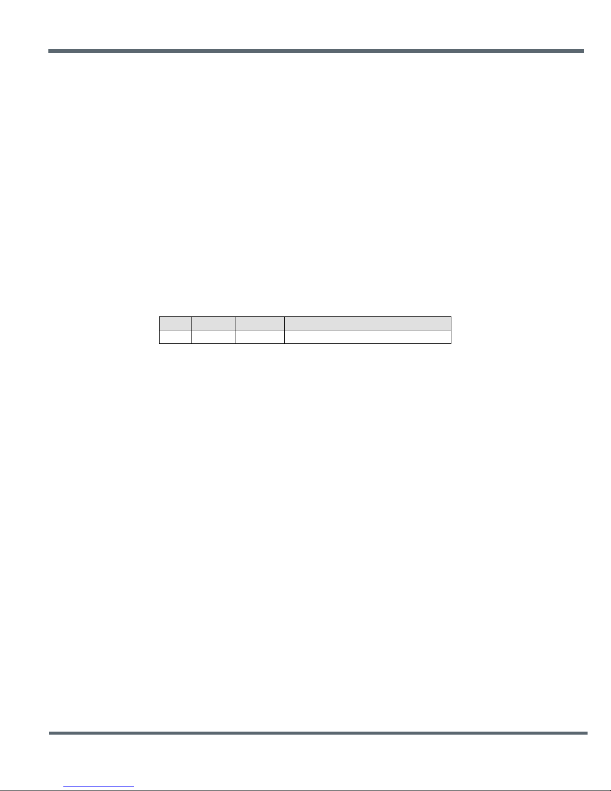
protocol-formatted messages have a common header as shown in Figure 7.1.1:
Figure 7.1.1
The scale above is in bytes.
The Start-of-Packet (SOP) character, 0xFB, is used to mark the beginning of a protocol-formatted
message and to assure synchronization in the event of a glitch on the serial port at startup.
The Length byte is defined as the length of the remainder of the message following the length byte itself,
or the length of the entire message - 2.
The Packet Type (PktType) byte specifies the type of message. It is a bitfield-oriented specifier, decoded
as follows:
Bits 7..6 Reserved for future use
Bit 5 Event - this bit is set to indicate an event message
Bit 4 Reply - this bit is set to indicate a message is a reply
Bits 3..0 Type - these bits indicate the message type
As indicated, the lower four bits (3..0) specify a message type. Bit 4 indicates that the message is a reply.
A reply message has the original command type in bits 3..0, with Bit 4 set to one. Bit 5 indicates an event
message. Arguments vary in size and number depending on the type of message and whether it is a
message sent from the host, or is a reply or event message from the radio. See Section 7.3 below.
7.2 Message Types
Messages sent to the module on the serial interface by the user are referred to as host messages.
Messages generated on the serial interface by the radio are referred to as reply or event messages. Host
messages carry commands. For most commands, there is a corresponding reply message. For example,
when the host sends a TxData command message, the radio can return a TxDataReply message to
indicate the status of the transmission - whether it succeeded or failed. To assist in interpreting the
©2009-2015 by Murata Electronics N.A., Inc.
DN24G/GI Series User Guide Rev. 2.0 01-09-15 Page 21 of 44 www.murata.com
Page 22
Command
Reply
Event
Type
Direction
Min Slot Size
0x00
- - EnterProtocolMode
from Host
N/A
-
0x10
-
EnterProtocolModeReply
from Radio
N/A
0x01
- - ExitProtocolMode
from Host
N/A
0x02
- - DeviceReset
from Host
N/A
-
0x12
-
DeviceResetReply
from Radio
N/A
0x03
- - GetRegister
from Host
N/A
-
0x13
-
GetRegisterReply
from Radio
N/A
0x04
- - SetRegister
from Host
N/A
-
0x14
-
SetRegisterReply
from Radio
N/A
0x05
- - TxData
from Host
length value -0x03
-
0x15
-
TxDataReply
from Radio
0x01
0x06
- - GetRemoteRegister
from Host
0x03
-
0x16
-
GetRemoteRegisterReply
from Radio
0x14
0x07
- - SetRemoteRegister
from Host
0x13
-
0x17
-
SetRemoteRegisterReply
from Radio
0x04
-
-
0x26
RxData
from Radio
length value -0x03
-
-
0x27
Announce/Error
from Radio
0x07
Enter Protocol Mode Command
Byte Offset
Field
Description
0x00
Start-of-Packet
0xFB = Indicates start of protocol formatted message
0x01
Length
0x07 = Number of bytes in message following this byte
0x02
Packet Type
0x00 = EnterProtocolMode
0x03 - 0x08
Payload
String = “DNTCFG” or 0x44 0x4E 0x54 0x43 0x46 0x47
command-reply data flow, the direction is indicated by the high nibble in the message type. For example,
an EnterProtocolMode command from the host is a message type 0x00, and the
EnterProtocolModeReply from the radio is a message type 0x10.
Event messages from a DN-24, such as received data or status announcements make up a third category
of messages. Event messages, including RxData, RxEvent and Announce packets are indicated by 0x20
in the high nibble of the type byte. If multiple arguments are to be provided, they are to be concatenated
in the order shown in Section 7.3 below. Little-Endian byte order is used for all multi-byte
arguments except text strings. Little-Endian byte order places the lowest order byte in the left-most byte
of the argument and the highest order byte in the right-most byte of the argument.
7.3 Message Format Details
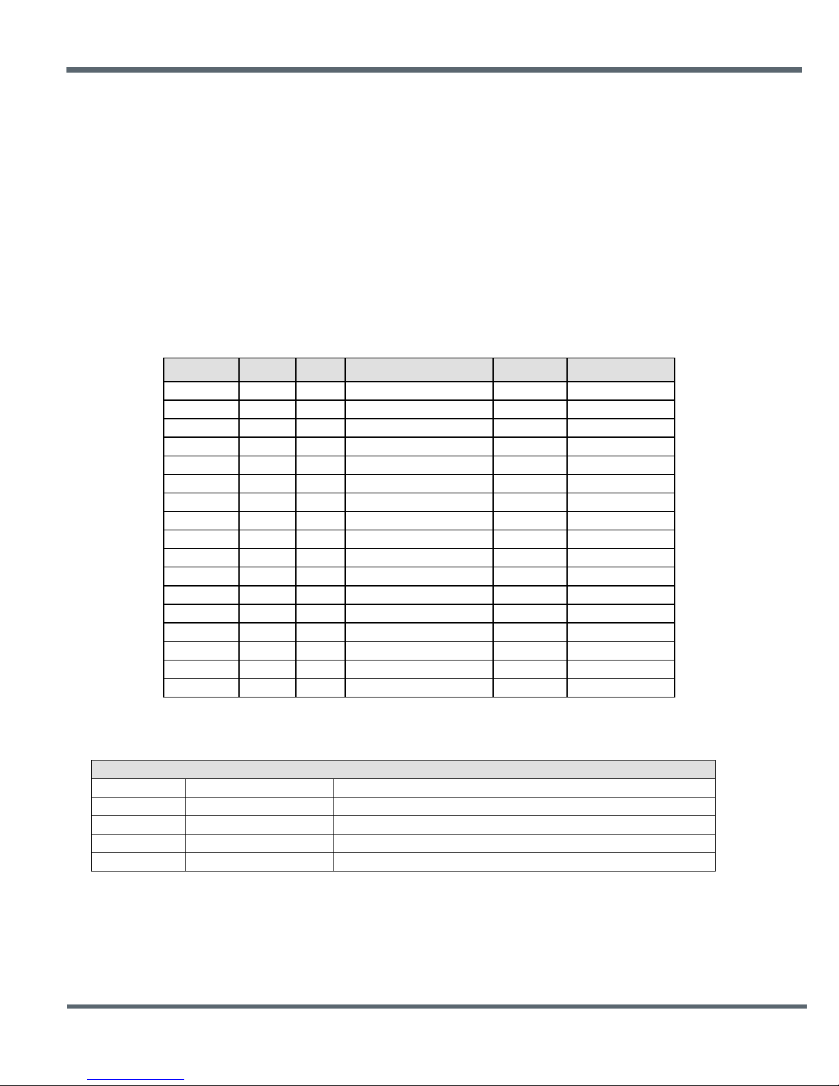
Table 7.3.1 below summarizes the DN-24 protocol-formatted messages:
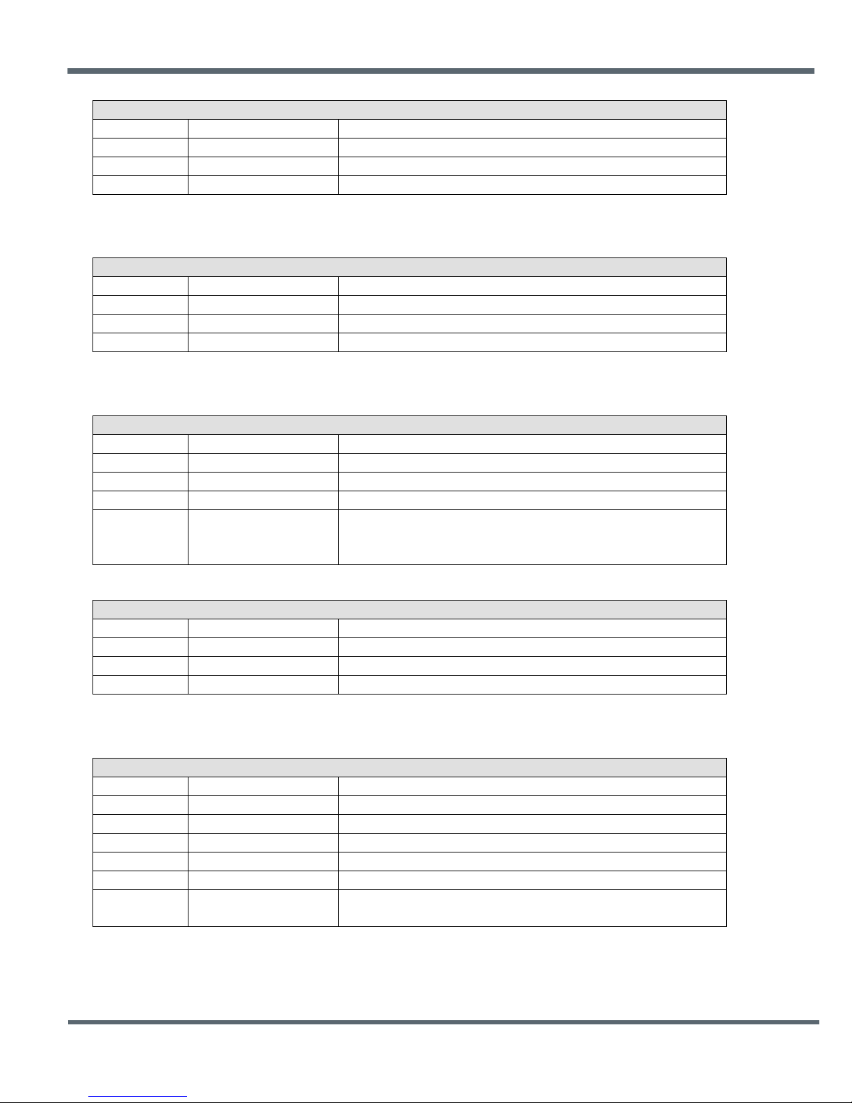
EnterProtocolMode command and reply format details are presented in Tables 7.3.2 and 7.3.3:
©2009-2015 by Murata Electronics N.A., Inc.
DN24G/GI Series User Guide Rev. 2.0 01-09-15 Page 22 of 44 www.murata.com
Table 7.3.1
Table 7.3.2
Page 23
Enter Protocol Mode Reply
Byte Offset
Field
Description
0x00
Start-of-Packet
0xFB = Indicates start of protocol formatted message
0x01
Length
0x01 = Number of bytes in message following this byte
0x02
Packet Type
0x10 = EnterProtocolModeReply
Exit Protocol Mode Command
Byte Offset
Field
Description
0x00
Start-of-Packet
0xFB = Indicates start of protocol formatted message
0x01
Length
0x01 = Number of bytes in message following this byte
0x02
Packet Type
0x01 = ExitProtocolMode
Device Reset Command
Byte Offset
Field
Description
0x00
Start-of-Packet
0xFB = Indicates start of protocol formatted message
0x01
Length
0x02 = Number of bytes in message following this byte
0x02
Packet Type
0x02 = DeviceReset
0x02 = Reset to Over-the-Air Bootloader
Device Reset Reply
Byte Offset
Field
Description
0x00
Start-Of-Packet
0xFB = I ndicates start of protocol formatted message
0x01
Length
0x01 = Number of bytes in message following this byte
0x02
Packet Type
0x12 = DeviceResetReply
Get Register Command
Byte Offset
Field
Description
0x00
Start-of-Packet
0xFB = Indicates start of protocol formatted message
0x01
Length
0x04 = Number of bytes in message following this byte
0x02
Packet Type
0x03 = GetRegister
0x03
Register Offset
Register offset in its bank
0x04
Register Bank
Register bank number
produce an error response)
ExitProtocolMode command format details are shown in Table 7.3.4:
DeviceReset command and reply format details are shown in Tables 7.3.5 and 7.3.6:
Table 7.3.3
Table 7.3.4
0x00 = Normal Device Reset
0x03 Reset Type
0x01 = Reset to Serial Bootloader
Table 7.3.5
Table 7.3.6
GetRegister command and reply format details are shown in Tables 7.3.7 and 7.3.8:
0x05 Register Size Regist er si ze in bytes, onl y one parameter at a time (wrong register size will
©2009-2015 by Murata Electronics N.A., Inc.
DN24G/GI Series User Guide Rev. 2.0 01-09-15 Page 23 of 44 www.murata.com
Table 7.3.7
Page 24
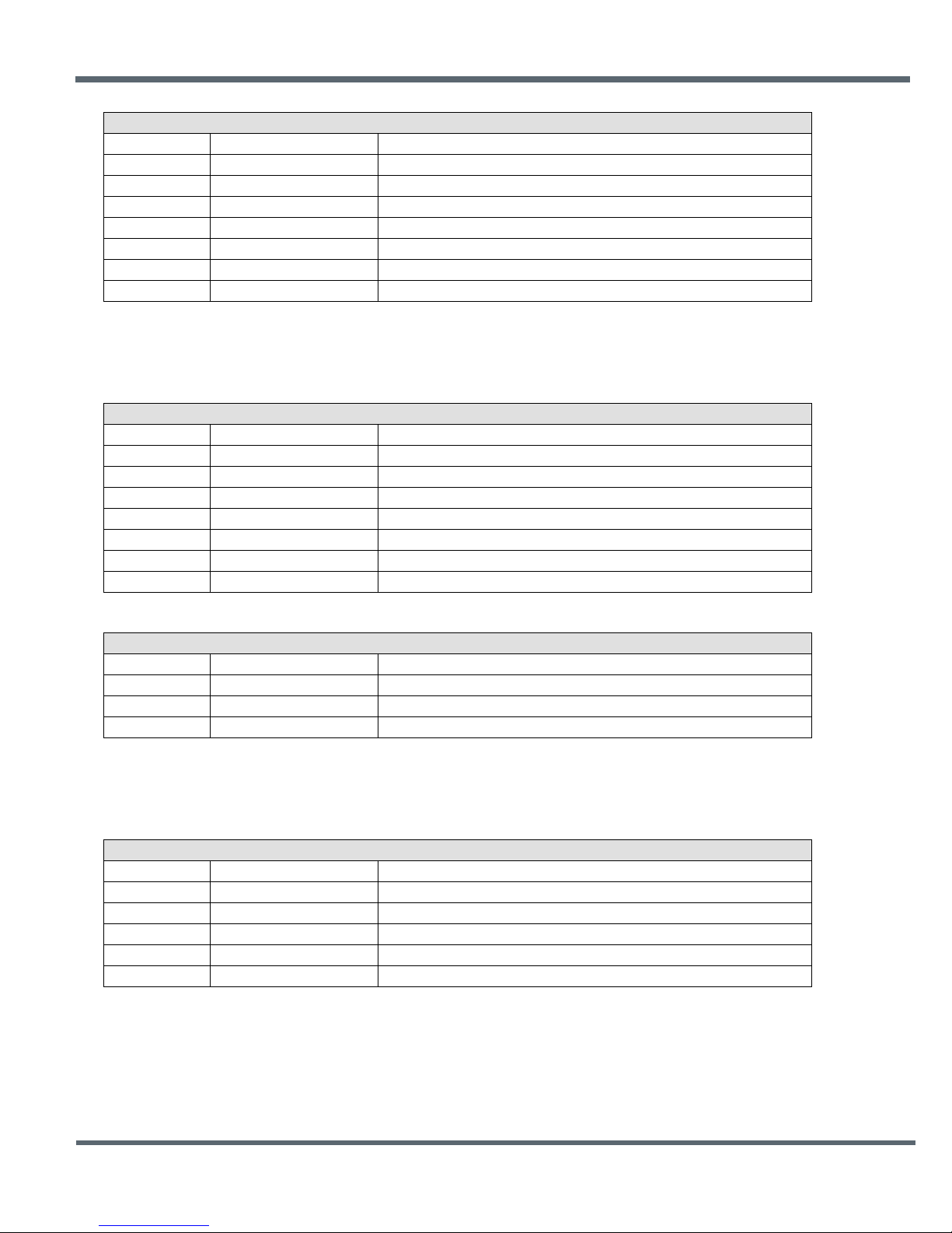
Get Register Reply
Byte Offset
Field
Description
0x00
Start-of-Packet
0xFB = Indicates start of protocol formatted message
0x01
Length
0x05 to 0x20 = Number of bytes in message following this byte
0x02
Packet Type
0x13 = GetRegisterReply
0x03
Register Offset
Register offset in its bank
0x04
Register Bank
Register bank number
0x05
Register Size
Register size in bytes
0x06 - 0x15
Register Value
Register value, all bytes in the register (only one parameter at a time)
Set Register Command
Byte Offset
Field
Description
0x00
Start-of-Packet
0xFB = Indicates start of protocol formatted message
0x01
Length
0x05 to 0x20 = Number of bytes in message following this byte
0x02
Packet Type
0x04 = SetRegister
0x03
Register Offset
Register offset in its bank
0x04
Register Bank
Register bank number
0x05
Register Size
Register size in bytes
0x06 - 0x15
Register Value
Register value, all bytes in the register (only one parameter at a time)
Set Register Reply
Byte Offset
Field
Description
0x00
Start-of-Packet
0xFB = Indicates start of protocol formatted message
0x01
Length
0x01 = Number of bytes in message following this byte
0x02
Packet Type
0x14 = SetRegisterReply
TX Data Command
Byte Offset
Field
Description
0x00
Start-of-Packet
0xFB = Indicates start of protocol formatted message
0x01
Length
= Number of bytes in message following this byte
0x02
Packet Type
0x05 = TxData
0x03 - 0x05
Destination MAC Address
Destination MAC address, in Little Endian byte order
0x06 - 0x72
Tx Dat a
Up to 109 bytes of data to Base, or 105 bytes from Base
Note: an Error message will be returned instead of a GetRegisterReply in case of a format error.
SetRegister command and reply format details are shown in Tables 7.3.9 and 7.3.10:
Table 7.3.8
Table 7.3.9
Note: an Error message will be returned instead of a SetRegisterReply in case of a format error.
Table 7.3.10
TXData command and reply format details are shown in Tables 7.3.11 and 7.3.12:
Table 7.3.11
©2009-2015 by Murata Electronics N.A., Inc.
DN24G/GI Series User Guide Rev. 2.0 01-09-15 Page 24 of 44 www.murata.com
Page 25
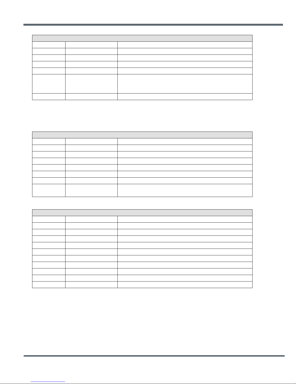
TX Data Reply
Byte Offset
Field
Description
0x00
Start-of-Packet
0xFB = Indicates start of protocol formatted message
0x01
Length
0x07 = Number of bytes in message following this byte
0x02
Packet Type
0x15 = TxDataReply
0x03 - 0x05
Destination MAC Address
Destination MAC address, in Little Endian byte order
0x02 = “Device Not Linked” error
0x07
RSSI
Packet RX power in dBm, -128 to 126 or 127 if invalid
Get Remote Register Command
Byte Offset
Field
Description
0x00
Start-of-Packet
0xFB = Indicates start of protocol formatted message
0x01
Length
0x07 = Number of bytes in message following this byte
0x02
Packet Type
0x06 = GetRemoteRegister
0x03 - 0x05
Destination MAC Address
Destination MAC address, in Little Endian byte order
0x06
Register Offset
Register offset in its bank
0x07
Register Bank
Register bank number
produce an error response)
Get Remote Register Reply
Byte Offset
Field
Description
0x00
Start-of-Packet
0xFB = Indicates start of protocol formatted message
0x01
Length
0x0A to 0x25 = Number of bytes in message following this byte
0x02
Packet Type
0x16 = GetRemoteRegisterReply
0x03
Status
Error status (0x00 = No Error, 0xE1 = Invalid Argument)
0x04 - 0x06
Originator MAC Address
Originator’s MAC address, in Little Endian byte order
0x07
RSSI
(-128 to 126 or 127 if invalid)
0x08
Register Offset*
Register offset in its bank
0x09
Register Bank*
Register bank number
0x0A
Register Size*
Register size in bytes
0x0B - 0x1A
Register Value*
Register value, all bytes in the register (only one parameter at a time)
0x00 = ACK received from destination
0x06 Status
Note: TxDataReply messages are only returned to the host when the EndToEndAckEnable parameter is set to 0x01.
GetRemoteRegister c om mand and r eply details are shown it Tables 7.3.13 and 7.3.1 4:
0x01 = no ACK received from destination (NAK)
Table 7.3.12
0x08 Register Size Regist er si ze in bytes, onl y one parameter at a time (wrong register size will
Table 7.3.13
*Bytes eight through the end of the message will not be returned in case of an error
Table 7.3.14
©2009-2015 by Murata Electronics N.A., Inc.
DN24G/GI Series User Guide Rev. 2.0 01-09-15 Page 25 of 44 www.murata.com
Page 26
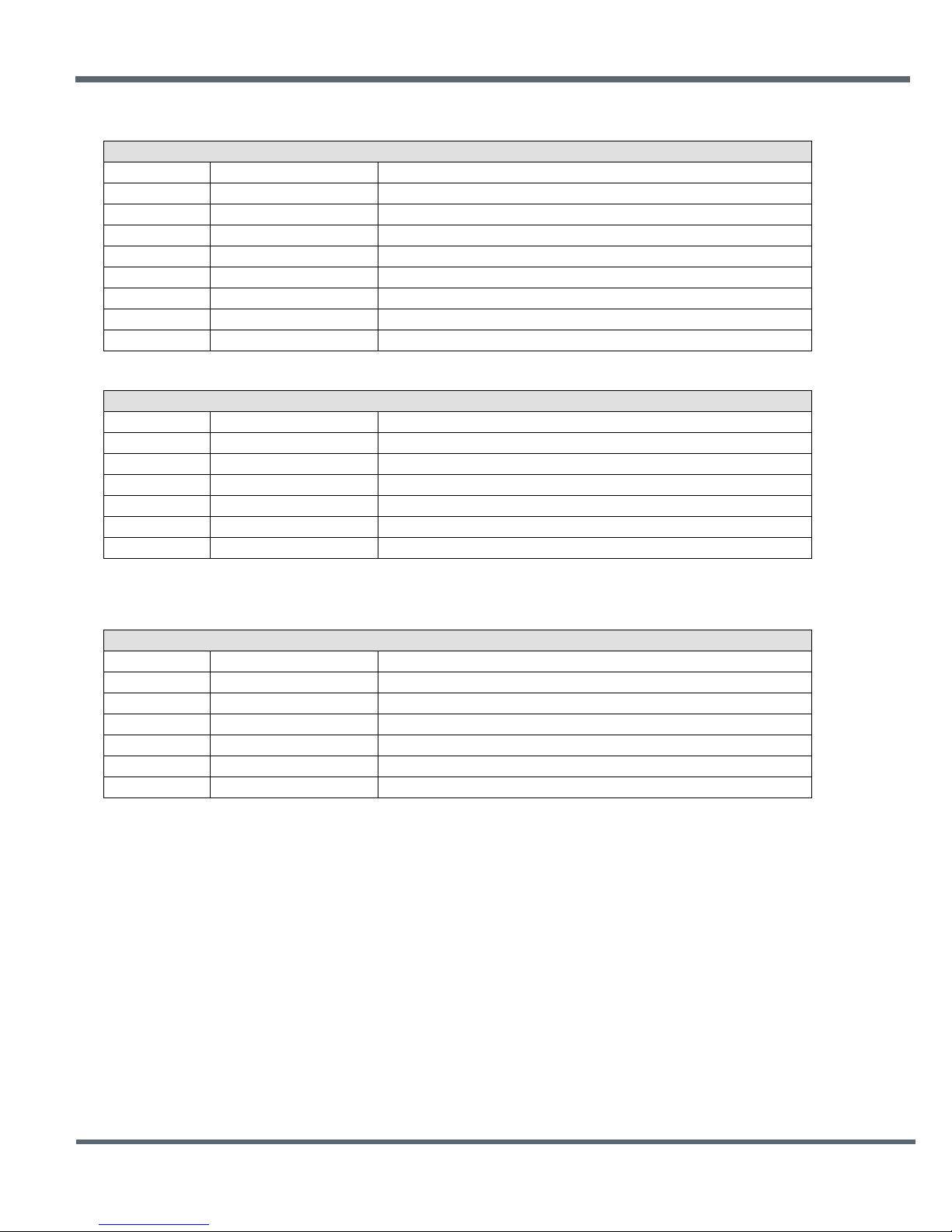
Set Remote Register Command
Byte Offset
Field
Description
0x00
Start-of-Packet
0xFB = Indicates start of protocol formatted message
0x01
Length
Number of bytes in message following this byte
0x02
Packet Type
0x07 = SetRemoteRegister
0x03 - 0x05
Destination MAC Address
Destination MAC address, in Little Endian byte order
0x06
Register Offset
Register offset in its bank
0x07
Register Bank
Register bank number
0x08
Register Size
Register size in bytes
0x09 - 0x18
Register Value
Register contents
Set Remote Register Reply
Byte Offset
Field
Description
0x00
Start-of-Packet
0xFB = Indicates start of protocol formatted message
0x01
Length
0x06 = Number of bytes in message following this byte
0x02
Packet Type
0x17 = SetRemoteRegisterReply
0x03
Status
Error status: 0x00 = no error, 0xE1 = invalid argument
0x04 - 0x06
Originator MAC Address
Originator’s MAC address, in Little Endian byte order
0x07
RSSI
Packet RX power in dBm, -128 to 126, or 127 if invalid
RX Data Packet
Byte Offset
Field
Description
0x00
Start-of-Packet
0xFB = Indicates start of protocol formatted message
0x01
Length
0x00 to 0x6D = Number of bytes in message following this byte
0x02
Packet Type
0x26 = RxData event message
0x03 - 0x05
Originator MAC Address
Originator’s MAC address, in Little Endian byte order
0x06
RSSI
Packet RX power in dBm, -128 to 126, or 127 if invalid
0x07 - 0x73
Rx Data
Up to 105 bytes of data from Base, up to 109 bytes from Router or Remote
SetRemoteRegister command and reply format details are shown in Tables 7.3.15 and 7.3.16:
Table 7.3.15
Table 7.3.16
RxData event packet format details are shown in Figure Table 7.3.17:
Table 7.3.17
©2009-2015 by Murata Electronics N.A., Inc.
DN24G/GI Series User Guide Rev. 2.0 01-09-15 Page 26 of 44 www.murata.com
Page 27
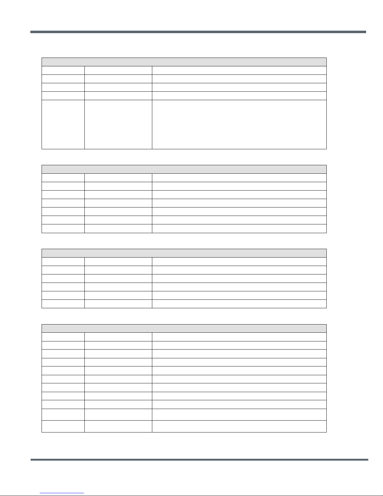
Startup Announcement or Error Code
Byte Offset
Field
Description
0x00
Start-of-Packet
0xFB = Indicates start of protocol formatted message
0x01
Length
0x02 = Number of bytes in message following this byte
0x02
Packet Type
0x27 = Indicates this is an Announce/Error message
0xEE = Hardware Error (Crystal or Radio Error)
Join Announcement
Byte Offset
Field
Description
0x00
Start-of-Packet
0xFB = Indicates start of protocol formatted message
0x01
Length
0x06 = Number of bytes in message following this byte
0x02
Packet Type
0x27 = Indicates this is an Announce/Error message
0x03
Announce Status
0xA3 = Joined network
0x04
Network ID
ID of network that was joined
0x05 - 0x07
Parent MAC Address
MAC address of parent, in Little Endian byte order
Exit Announcement
Byte Offset
Field
Description
0x00
Start-of-Packet
0xFB = Indicates start of protocol formatted message
0x01
Length
0x03 = Number of bytes in message following this byte
0x02
Packet Type
0x27 = Indicates this is an Announce/Error message
0x03
Announce Status
0xA4 = Exited network
0x04
Network ID
ID of network that was exited
Heartbeat Announcement
Byte Offset
Field
Description
0x00
Start-of-Packet
0xFB = Indicates start of protocol formatted message
0x01
Length
0x0C = number of bytes in message following this byte
0x02
Packet Type
0x27 = Indicates this is an Announce/Error message
0x03
Announce Status
0xA8 = Heartbeat message
0x04 - 0x06
Device MAC Address
MAC address of originator, in Little Endian byte order
0x07 - 0x09
Parent MAC Address
MAC address of parent, in Little Endian byte order
0x0A
Parent Network ID
Network ID of device’s parent
0x0B
Base Mode Network ID
Network ID if device is a router, otherwise 0xFF
Average beacon RX power in dBm, uses 0.0625 “alpha” averaging filter,
-128 to 126 or 127 if invalid
RX power of packet as received by device’s parent in dBm, -128 to 126 or
127 if invalid
Announce/Error message format details are shown in Tables 7.3.18 through 7.3.21:
0xA0 = Startup initialization complete
0xE1 = Invalid argument
0x03 Announce Status
0xE4 = Register read only error
0xEC = Brownout reset
0xED = Watchdog reset
Table 7.3.18
0x0C Beacon RX Power
Table 7.3.19
Table 7.3.20
0x0D Parent RX Power
©2009-2015 by Murata Electronics N.A., Inc.
DN24G/GI Series User Guide Rev. 2.0 01-09-15 Page 27 of 44 www.murata.com
Table 7.3.21
Page 28
Bank
Location
Name
R/W
Size
Range
Default
0x00
0x00
DeviceMode
R/W
0x01
0..2
0 (remote)
0x00
0x01
HopDuration
R/W
0x01
16..200
40 (20 ms)
0x00
0x02
ParentNwkID
R/W
0x01
0..63, 255
255 (any parent)
0x00
0x03
SecurityKey
R/W
0x10
0..2^128-1
0
0x00
0x13
SleepModeEn
R/W
0x01
0..2
0 (off)
0x00
0x14
WakeResponseTime
R/W
0x02
0..30000
500 (500 ms)
0x00
0x16
WakeLinkTimeout
R/W
0x01
0..255
5 (5 s)
0x00
0x17
AltParentNwkID
R/W
0x01
0..63, 255
255 (disabled)
0x00
0x18
TxPower
R/W
0x01
0..1
1 (+22 dBm)
0x00
0x19
UserTag
R/W
0x10
string
“DN-24”
0x00
0x29
RmtTransDestAddr
R/W
0x03 0x000000 (Base)
0x00
0x2C
Store&ForwardEn
R/W
0x01
0..1
0 (disabled)
0x00
0x2D
BaseModeNetID
R/W
0x01
1..63, 255
0xFF
0x00
0x2E
HeartbeatIntrvl
R/W
0x02
0..65535
0xFFFF (disabled)
0x00
0x30
SystemId
R/W
0x01
0..255
0
0x00
0x31
EndToEndAckEnable
R/W
0x01
0..1
0 (disabled)
0x00
0x32
LinkRetryInterval
R/W
0x02
0..65535
0 (off)
0x00
0x34
FastBeaconCount
R/W
0x02
0..65535
0 (off)
0x00
0x35
FastBeaconTrig
R/W
0x01
0..255
0 (off)
7.4 Configuration Parameter Registers
The configuration parameters in a DN-24 module are stored in a set of variable length registers. Most
registers are read-write, with a few read-only or write-only. Changes made to the register settings are
temporary until a MemorySave command is executed. Resetting or power-cycling the module will clear
any changes that have not been saved to permanent memory using the MemorySave command. DN-24
modules can be configured to start in protocol mode at power-up, in which case the EnterProtocolMode
command is not required. Some configuration parameters native to the DNT24 radio used in the DN-24
modem do not apply to DN-24 serial modem operation. The parameters are grayed out in the tables
shown below.
7.4.1 Bank 0x00 - Transceiver Setup
DeviceMode - this parameter selects the operating mode for the radio:
0x00 = remote (default)
0x01 = base
0x02 = router (store and forward system)
Note that changing this setting does not take effect immediately. It must be followed by a MemorySave
command and then either a hardware or software reset or a power off/on cycle. A router without a valid
BaseModeNetID operates as a remote.
HopDuration - this parameter sets the duration of the hop frame, and can only be set on the base. The
duration is an 8-bit value, 0.5 ms/count. The valid range is from 8 to 100 ms. Changing the hop duration
on the base must be followed by a MemorySave command to allow the change to persist through a reset
or power cycle. A HopDuration change takes effect immediately. Child radios will re-link following a
HopDuration parameter change as they receive the updated hop duration value from the base.
©2009-2015 by Murata Electronics N.A., Inc.
DN24G/GI Series User Guide Rev. 2.0 01-09-15 Page 28 of 44 www.murata.com
Table 7.4.1.1
Page 29

ParentNwkID - this parameter specifies the parent (BaseModeNetID) that a child radio is allowed to join.
The valid range of this parameter is 0 to 63 (0x00 to 0x3F), plus 255 (0xFF). Setting the ParentNwkID to
255 allows connection to any parent. This parameter is applicable only to remotes and routers. Also see
the discussion of AltParentNwkID below.
Security Key - this 16-byte parameter sets the 128-bit AES encryption key. To protect the key, it is a writeonly parameter for the user. It always reads back as 0x2A.
AltParentNwkID - this parameter specifies an alternate parent (BaseModeNetID) that a child radio is
allowed to join. This parameter is used to provide more robust message routing when setting the
ParentNwkID to its 0xFF wildcard value is not appropriate. The valid range of this parameter is 0x00 to
0x3F, plus 0xFF. Rather than specifying wildcard operation, setting the AltParentNwkID to 0xFF disables
the selection of an alternate parent. This parameter is applicable only to remotes and routers.
TxPower - this parameter sets the transmit power level (default is 0x01):
0x00 = +10 dBm or 10 mW
0x01 = +18 dBm or 63 mW
UserTag - this parameter is a user definable field intended for use as a location description or other
identifying tag such as a “friendly name”.
RmtTransDestAddr - this parameter holds the default destination for transparent mode data packets and
event packets. This parameter defaults to the base station’s address (0x000000) except on a base
station, where at startup it will be changed to the broadcast address (0xFFFFFF) if the firmware detects
that it is set to 0x000000. Note - if a module’s configuration is changed from a base to a remote or router,
this parameter must be set back to 0x000000 or the module will send broadcast packets in transparent
mode or for event packets.
Store&ForwardEn - setting this parameter to 0x01 enables store-and-forward system operation. Storeand-forward operation is disabled by default.
BaseModeNetID - applicable to the base and routers only, this parameter specifies the network ID of a
device’s own network when acting as parent. A child is allowed to join a network when its ParentNwkID
parameter matches a parent’s BaseModeNetID. The valid range of this parameter is 0x00 to 0x3F. A
value greater than 0x3F is invalid and will be forced to 0x00 on a base. A router with an invalid Base-
ModeNetID will be forced to operate as a remote.
HeartbeatInterval - when set to 0, all heartbeats are disabled, including the initial heartbeat issued after
link acquisition. When set to 0xFFFF (default), periodic heartbeats are disabled but the initial linkup
heartbeat is enabled. The periodic heartbeat interval is scaled 1 second/count, and applies to DN-24s
where sleep mode is disabled. Remotes with sleep mode enabled must have periodic reports and/or ADC
sampling enabled for heartbeats to be generated.
SystemId - this parameter holds the ID for a DTN24 system. DN-24 systems that may physically overlap
must have different system IDs.
EndToEndAckEnable - when this parameter is set to 1 and the module is in protocol mode, the originator
will indicate in its transmitted packet that an ACK is expected from the packet’s destination node. Setting
this parameter to 0x00 reduces network congestion in a store-and-forward system, but no TxDataReply
will be sent from the destination to confirm reception.
©2009-2015 by Murata Electronics N.A., Inc.
DN24G/GI Series User Guide Rev. 2.0 01-09-15 Page 29 of 44 www.murata.com
Page 30
Bank
Location
Name
R/W
Size
Range
Default
0x01
0x00
InitFrequencyBand
R/W
0x01
0..11, 255
0 (US)
0x01
0x01
NumSlots
R/W
0x01
1..8
3
0x01
0x02
BaseSlotSize
R/W
0x01
6..105
40
0x01
0x03
SlotLease
R/W
0x01
1..255
2 (hops)
0x01
0x04
BcstAttemptLimit
R/W
0x01
0..254
1
0x01
0x05
ArqAttemptLimit
R/W
0x01
1..255
6
0x01
0x06
LinkDropThreshold
R/W
0x01
1..255
10 (hops)
0x01
0x07
P2PReplyTimeout
R/W
0x01
0..255
100 (hops)
0x01
0x08
0x01
0x09
NumBaseParms
R/W
0x01
8..21
21
Subband
Channels
Frequency Range(s)
Notes
0x00
24
2406 - 2475 MHz
General purpose 24 channel band
0x01
15
2433 - 2475 MHz
15 channel band, avoids 802.11b/g channels 1-2
0x02
15
2406 - 2475 MHz
15 channel band, avoids 802.11b/g channels 3
0x03
15
2406 - 2475 MHz
15 channel band, avoids 802.11b/g channels 4
0x04
15
2406 - 2475 MHz
0x05
15
2406 - 2475 MHz
0x06
15
2406 - 2475 MHz
15 channel band, avoids 802.11b/g channels 7
0x07
15
2406 - 2475 MHz
0x08
15
2406 - 2475 MHz
0x09
15
2406 - 2475 MHz
0x0A
15
2406 - 2475 MHz
0x0B
15
2406 - 2448 MHz
0x0C 5 2406 - 2466 MHz
0x0D 5 2415 - 2475 MHz
0xFF
Auto
Auto
Autoscan for remote to match base
LinkRetryInterval - when a remote enters sleep mode with any packet unsent in its transmit queue, if this
parameter is set to a non-zero value, the remote will wake up after the specified number of seconds and
try to link so that pending packets can be transmitted. When set to 0, this feature is disabled.
7.4.2 Bank 0x01 - System Settings
Bank 1 holds configuration parameters to be input to the base only. The base passes these parameters to
the routers and remotes as needed. The exception is InitFrequencyBand parameter which can also be set
in routers and remotes.
RegistryTimeout R/W 0x01 0..255 50 (hops)
Table 7.4.2.1
InitFrequencyBand - this parameter sets the range of frequencies and channel spacing over which the
DN-24 system will initially operate. Twelve bands are available:
15 channel band, avoids 802.11b/g channels 5
15 channel band, avoids 802.11b/g channels 6
15 channel band, avoids 802.11b/g channels 8
15 channel band, avoids 802.11b/g channels 9
15 channel band, avoids 802.11b/g channels 10
15 channel band, avoids 802.11b/g channels 11
15 channel band for operation in France
5 channel band for fast linking, use US and Canada only
5 channel band for fast linking, use in US and Canada only
Table 7.4.2.2
©2009-2015 by Murata Electronics N.A., Inc.
DN24G/GI Series User Guide Rev. 2.0 01-09-15 Page 30 of 44 www.murata.com
Page 31

NumSlots - this parameter sets the number of slots available for child transmissions following the parent’s
beacon transmission on a hop.
BaseSlotSize - this parameter set the maximum number of payload bytes that the base can send on a
single hop. The default value is 40 bytes.
SlotLease - this parameter set the number of hops a parent radio will reserve a slot for a child after
receiving a message from that child. Small values such as 2 are suited to short data bursts, and larger
values are generally a better choice when devices send a stream of non-continuous data across
consecutive hops. The minimum value is 1, assuring that a child can receive an ACK on the next hop
after it transmits.
BcstAttemptLimit - setting this parameter to 0 enables automatic broadcast message repeats based on
the ArqAttemptLimit parameter value. Setting this parameter to a value between 1 and 254 specifies the
number of broadcast message repeats independent of the ArqAttemptLimit. This parameter should not be
set to 0 if ArqAttemptLimit is set to 255.
ArqAttemptLimit - this sets the maximum number of attempts that will be made to send a message on the
RF link. Setting this parameter to the maximum value of 255 is a flag value indicating that there should be
no limit to the number of attempts to send each packet (infinite number of attempts). This mode is
intended for point-to-point networks in serial data cable replacement applications where absolutely no
packets can be lost. Note - if this mode is used in a multipoint network, one remote that has lost link will
shut down the entire network if the base is trying to send it data.
LinkDropThreshold - this is the number of consecutive beacons missed by a remote that causes the
remote to restart a link acquisition search. Please contact
changes to the parameter.
P2PReplyTimeout - this parameter sets the reply timeout for peer-to-peer messages sent from one node
to another. Because each leg of the journey from one node to another and back may take multiple
transmit attempts, the length of time to confirm receipt and issue a TxDataReply is subject to more
variation than a transmission directly between a base and a remote. When AckEnable is selected, the
P2PReply-Timeout parameter specifies the maximum number of hops or hop pairs that a remote will wait
for a reply from its recipient. If a reply returns sooner than the timeout, the remote will send a
TxDataReply indicating success (ACK) to its host as soon as it is received, and cancels the timeout. If a
reply does not come back before the timeout expires, the remote will send a TxDataReply to its host
indicating failure (NAK). If a reply should come back after the timeout expires the remote will ignore it, as
a TxDataReply has already been sent. The units of this parameter are in hops for point-to-point and pointto-multipoint operation and in hop pairs for store-and-forward operation.
RegistryTimeout - this parameter sets the number of hops without contact from a child device for which a
parent device will preserve the Transaction ID (TID) history for that child. The TID is used to filter out
duplicate packets. After a registry timeout occurs, the TID history is discarded.
NumBaseParms - this parameter controls the number of cycled parameters sent in the base station
beacon. It must be left in its default value of 21 until all nodes in a DN-24 system have received all cycled
parameters and stored them locally in EEPROM. At this point the number of cycled parameters can be
set to 8, which will significantly speed up future system resynchronizations.
Murata technical support before making
©2009-2015 by Murata Electronics N.A., Inc.
DN24G/GI Series User Guide Rev. 2.0 01-09-15 Page 31 of 44 www.murata.com
Page 32
Bank
Location
Name
R/W
Size
Range
Default
0x02
0x00
MacAddress
R
0x03
0..0xFFFFFF
Fixed value
0x02
0x03
CurrNwkID
R
0x01
0..63, 255
Current Value
0x02
0x04
CurrFreqBand
R
0x01
0..2, 255
Current Value
0x02
0x05
LinkStatus
R
0x01
0..6
Current status
0x02
0x06
RemoteSlotSize
R
0x01
0..109
Current Value
0x02
0x07
SlotNumber
R
0x01
0..7
Current Value
0x02
0x08
HardwareVersion
R
0x01
0x41..0x5A
0x43 = Rev “C”
0x02
0x09
FirmwareVersion
R
0x01
0x00..0xFF
Current FW load
0x02
0x0A
FirmwareBuildNum
R
0x02
0..65535
Current FW load
0x02
0x0C
FirmwareBuildDate
R
0x03
BCD (“YYMMDD”)
Current FW load
0x02
0x0F
FirmwareBuildTime
R
0x03
BCD (“HHMMSS”)
Current FW load
0x02
0x12
RssiIdle
R
0x01
-128..127
Current Value
0x02
0x13
RssiLast
R
0x01
-128..127
Current Value
0x02
0x14
AvgBeaconPower
R
0x01
-128..127
Current Value
0x02
0x15
ParentMacAddress
R
0x03
0..0xFFFFFF
Current Value
0x02
0x18
ModelNumber
R
0x01
0x24, 0x90
0x24 = DN-24
7.4.3 Bank 0x02 - Status Param ete rs
MacAddress - this parameter holds the radio's unique 24-bit MAC address.
CurrNwkID - this parameter holds the ID of the network the radio is currently assigned to or connected to.
A value of 255 (0xFF) means the radio has powered up and is scanning for a network but has not yet
joined one.
CurrFreqBand - this parameter holds the frequency band of the network that the radio is currently
assigned to or connected to. A value of 0xFF means the radio has powered up and is scanning for a
network but has not yet joined one.
LinkStatus - this parameter holds the link status of a router or remote:
0x00 = idle
0x01 = lost link
0x02 = acquiring link
0x03 = collecting parameters from the base
0x04 = registering
0x05 = registered
0x06 = linked in fast beacon mode
RemoteSlotSize - this parameter holds the current remote slot size, defined as the maximum number of
message bytes a remote can send on a single hop. The RemoteSlotSize is calculated by each radio in a
system based on the values of the HopDuration, BaseSlotSize, and NumSlots parameters.
SlotNumber - this parameter holds the current slot number assigned to a router or remote.
HarwareVersion - this parameter holds an identifier indicating the hardware revision (ASCII character). A
value of 0x43 is defined for the DN-24 Revision C hardware.
FirmwareVersion - this parameter holds the firmware version of the radio in 2-digit BCD format.
Table 7.4.3.1
©2009-2015 by Murata Electronics N.A., Inc.
DN24G/GI Series User Guide Rev. 2.0 01-09-15 Page 32 of 44 www.murata.com
Page 33
Bank
Location
Name
R/W
Size
Range
Default
0x03
0x00
SerialRate
R/W
0x01
0..10
3 (9600 baud)
0x03
0x01
SerialParams
R/W
0x01
0..7
0 (8-N-1)
0x03
0x02
SpiMode
R/W
0x01
0..2
0 (SPI disabled)
0x03
0x03
SpiRateSel
R/W
0x01
0..2
0 (125 kHz)
0x03
0x04
SpiOptions
R/W
0x01
0..7
0
0x03
0x05
SpiMasterCmdLen
R/W
0x01
0..16
0
0x03
0x06
SpiMasterCmdStr
R/W
0x10
0..16 byte string
All 0x00 bytes
FirmwareBuildNum - this parameter holds the firmware build number, in binary format.
FirmwareBuildDate - this parameter holds the date of firmware build in MM/DD/YY format.
FirmwareBuildTime - this parameter holds the time of the firmware build in HH:MM:SS format.
RssiIdle - this 2’s compliment parameter holds the last RSSI measurement in dBm made during a time
when the RF channel was idle. This parameter is useful for detecting interferers.
RssiLast - this 2’s compliment parameter holds the last RSSI measurement in dBm made during the
receipt of an RF packet with a valid CRC. This parameter is useful for network
commissioning/diagnostics.
AvgBeaconPower - this 2’s compliment parameter holds the alpha-filtered beacon power (dBm) received
from a device’s parent, where alpha = 0.0625.
ParentMacAddress - this parameter holds the MAC address of a DN-24’s parent.
ModelNumber - this parameter specifies the DNT model, in this case a DN-24.
7.4.4 Bank 0x03 - Serial Settings
Table 7.4.4.1
SerialRate - this parameter sets the serial data rate as shown below:
Setting Serial rate
0x00 1.2 kbps
0x01 2.4 kbps
0x02 4.8 kbps
0x03 9.6 kbps
0x04 14.4 kbps
0x05 19.2 kbps
0x06 28.8 kbps
0x07 38.4 kbps
0x08 57.6 kbps
0x09 115.2 kbps
0x0A 230.4 kbps
0x0B 250.0 kbps
©2009-2015 by Murata Electronics N.A., Inc.
DN24G/GI Series User Guide Rev. 2.0 01-09-15 Page 33 of 44 www.murata.com
Page 34
Bank
Location
Name
R/W
Size
Range
Default
0x04
0x00
ProtocolMode
R/W
0x01
0..1
0 (Transparent)
0x04
0x01
TxTimeout
R/W
0x01
0..255
0 (No timeout)
0x04
0x02
MinPacketLength
R/W
0x01
0..255
1 (byte)
0x04
0x03
TransPtToPtMode
R/W
0x01
0..1
1 (Last RX)
0x04
0x04
MsgsPerHop
R/W
0x01
1..8
8
SerialParams - this parameter sets the serial mode options for parity and stop bits:
Setting Mode
0x00 No parity, 8 data bits, 1 stop bit (default)
0x01 No parity, 8 data bits, 2 stop bits
0x02 Reserved
0x03 Reserved
0x04 Even parity, 8 data bits, 1 stop bit
0x05 Even parity, 8 data bits, 2 stop bits
0x06 Odd parity, 8 data bits, 1 stop bit
0x07 Odd parity, 8 data bits, 2 stop bits
Note that 8-bit data with no parity is capable of carrying 7-bit data with parity for compatibility without loss
of generality for legacy applications that may require it.
7.4.5 Bank 0x04 - Host Protocol Settings
Table 7.4.5.1
ProtocolMode - this parameter selects the host protocol mode. The default is 0x00, which is transparent
mode, meaning the radio conveys whatever characters that are sent to it transparently, without requiring
the host to understand or conform to the DN-24's built-in protocol. This setting is recommended for pointto-point applications for legacy applications such as wire replacements where another serial protocol may
already exist. Setting this parameter to 0x01 enables the DN-24 protocol formatting. It is not necessary to
define the same protocol mode for all radios in a network. For example, it is frequently useful to configure
all the remotes for transparent mode and the base for protocol mode. Note that it is possible for the host
to switch the radio from transparent mode to protocol mode and back as required by transmitting an
EnterProtocolMode command.
TxTimeout - this parameter is used to group transparent data to be sent in a single transmission rather
than being split over two hops. Messages sent over two hops can have gaps in the received data stream
that can cause problems for the receiving application - for example, Modbus RTU. This parameter is the
amount of time the DN-24 will wait without receiving a byte through the serial port before transmitting the
data. Parameter units are in milliseconds. A message boundary is determined whenever a gap between
consecutive characters is equal to or greater than the TxTimeout value, or the number of bytes reaches
the MinPacketLength. Either condition will trigger a transmission. The default TxTimeout value is 0 ms
which will have the radio send whatever data is in its transmit buffer as soon as possible.
MinPacketLength - this parameter is similar to TxTimeout except it uses the number of bytes received
instead of the amount of time without receiving a byte. The default is one byte. A transmission is triggered
when either the number of bytes reaches MinPacketLength or a gap is detected between consecutive
characters greater than TxTimeout. If this parameter is set larger than the applicable slot size, the slot
size overrides this parameter and a transmission is triggered when the slot size is filled.
TransPtToPtMode - when this parameter is set to 0x00, the destination address of transparent mode
packets will be the configured RemoteDestAddr. When set to 0x01, the destination address of transparent
mode packets will be the originator of the most recent RX packet processed.
©2009-2015 by Murata Electronics N.A., Inc.
DN24G/GI Series User Guide Rev. 2.0 01-09-15 Page 34 of 44 www.murata.com
Page 35
Bank
Location
Name
R/W
Size
Range
Default
0xFF
0x00
UcReset
W
0x01
0..2
N/A
0xFF
0x01
MemorySave
W
0x01
0xD0..0xD2
N/A
0xFF
0x04
DiagSerialRate
R/W
0x01
0..10
7 (38400 kbps)
0xFF
0x0C
ForceDiscover
W
0x03
(See Text)
N/A
0xFF
0x10
DiagPortEn
R/W
0x01
0..1
0 (disabled)
SOP
Length
PktType
Lo MAC
MAC
Hi MAC
“H”
“e”
“l”
“l”
“o”
0xFB
0x09
0x05
0x56
0x34
0x12
0x48
0x65
0x6C
0x6C
0x6F
SOP
Length
PktType
Lo MAC
MAC
Hi MAC
Status
RSSI
0xFB
0x07
0x15
0x56
0x34
0x12
0x00
0xB0
MsgsPerHop - this parameter sets the maximum number of messages a DN-24 can send in each hop
frame. The default value is 8 messages, which is suitable for most applications. Setting MsgsPerHop to a
low value allows message flow rate to be controlled.
7.4.6 Bank 0xFF - Special Functions
UcReset - writing a 0 to this parameter initiates a full reset, writing 1 to initiates a reset to the serial
bootloader, or writing a 2 to initiates a reset to the OTA bootloader client.
MemorySave - writing 0xD0 to this parameter load default values, writing 0xD1 saves settings to
EEPROM, or writing 0xD2 to save settings to EEPROM and resets the module.
ForceDiscoverRegister - a write to this register, typically using a broadcasted Set Remote Register
command, will force a heartbeat reply if a device's parent has the specified base-mode network ID (or
0xFF wildcard), and the least significant byte of the device’s MAC address is within a specified min/max
range. The payload consists of 3 bytes: NWKID (NN), minimum MAC address (LL), and maximum MAC
address (XX). In Little Endian hexadecimal format this would appear as “XXLLNN”.
7.5 Protocol-Formatted Data Message Example
In this example, the ASCII text “Hello” is sent from the base to a remote using the TxData command.
The MAC address of the remote is 0x123456. The protocol formatting for the host message is:
Table 7.4.6.1
There are 9 bytes following the length byte, so the length byte is set to 0x09. Note that the 0x123456
network address is entered in Little-Endian byte order, 56 34 12. When an ACK to this message is
received from the remote, the base outputs a TxDataReply message to its host:
The 0x00 TxStatus byte value indicates the ACK reception from the remote. The RSSI value of the
received ACK is 0xB0, indicating a received signal strength of approximately -80 dBm .
The ASCII “Hello” message is output at the remote as a 0x26 RxData event. The address field contains
the originator’s address, 0x00 0x00 0x00, which is the base. The RSSI value of the received message is
0xB4, indicating a received signal strength of approximately -76 dBm. The data following the RSSI value
is the “Hello” text.
©2009-2015 by Murata Electronics N.A., Inc.
DN24G/GI Series User Guide Rev. 2.0 01-09-15 Page 35 of 44 www.murata.com
Page 36
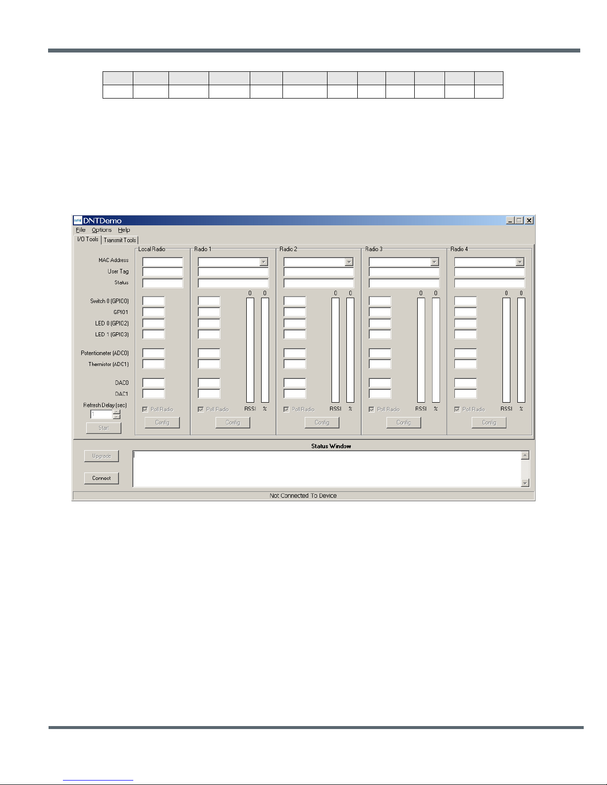
SOP
Length
PktType
Lo MAC
MAC
Hi MAC
RSSI
“H”
“e”
“l”
“l”
“o”
0xFB
0x0A
0x26
0x00
0x00
0x00
0x35
0x48
0x65
0x6C
0x6C
0x6F
Figure 8.6.1
Note that if the remote was in transparent mode, only the “Hello” text would be output.
8.0 DNT Demo Utility Program
The DNT Demo requires no installation and can be simply copied to the PC and run. It provides access to
all configuration parameters relevant to DN-24 series modem operation, and allows basic testing of DN24 series modems and systems.
1. Start the Demo on the PC. The Demo program start-up window is shown in Figure 8.1.
©2009-2015 by Murata Electronics N.A., Inc.
DN24G/GI Series User Guide Rev. 2.0 01-09-15 Page 36 of 44 www.murata.com
Page 37
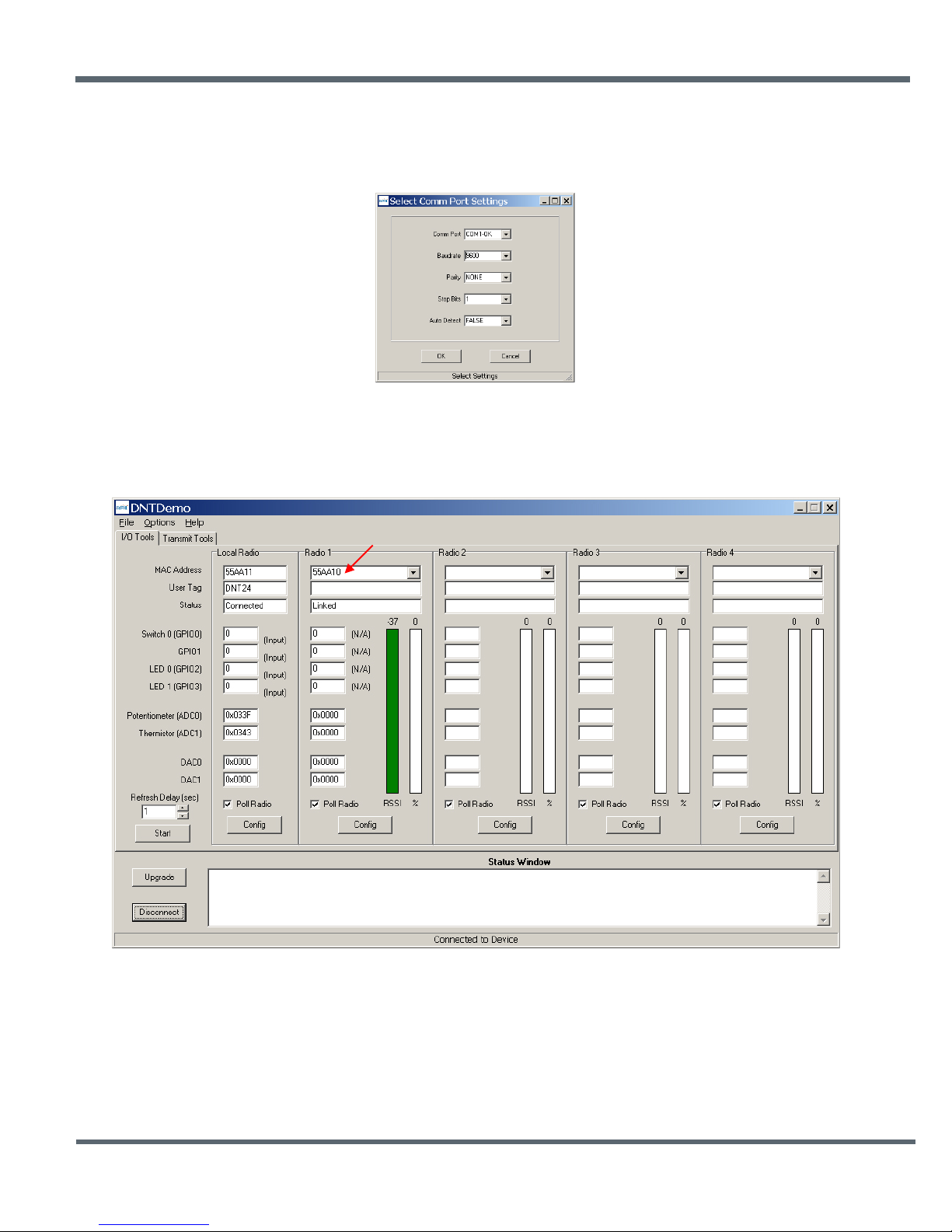
Figure 8.2
Figure 8.3
2. Click on Connect to open the Select Comm Port Settings dialog box, as shown in Figure 8.2. If
necessary, set the baud rate to 9600 bps. Set the CommPort to match the serial port connected to the
Base, either the hardware port or the USB virtual serial port. Then click OK to activate the connection.
3. At this point the utility program will collect data from the Base, filling in the Local Radio column as
shown in Figure 8.3.
4. Next power up a DN-24 Remote us ing a wall-plug power supply. The Remote will transmit a “heartbeat”
message on power up.
5. Click on the drop-down box at the top of the Radio 1 column and click on the M AC Addres s (preloaded
when the Remote is turned on after the Base), or load the MAC Addr es s for the Remote from the
heartbeat message.
©2009-2015 by Murata Electronics N.A., Inc.
DN24G/GI Series User Guide Rev. 2.0 01-09-15 Page 37 of 44 www.murata.com
Page 38
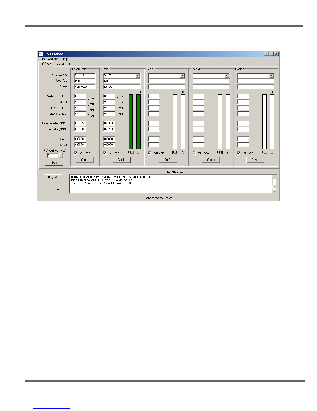
Figure 8.4
6. Next press the Start button using the default 1 second Refresh Delay.
7. DNT Demo will display data on the Remote in the Radio 1 column, including bar graphs of RSSI (signal
strength) and percent packet success rate, as shown in Figure 8.4. You can change the Refresh setting
from the drop down menu at the bottom left.
8.1 Serial Communication and Radio Configuration
Connect PCs to both the Base and the Remote for serial communication testing. Click the Stop button
under the Refresh Delay label on the I/O Tools tab and move to the Transmit Tools tab, as shown in
Figure 8.1.1.
©2009-2015 by Murata Electronics N.A., Inc.
DN24G/GI Series User Guide Rev. 2.0 01-09-15 Page 38 of 44 www.murata.com
Page 39
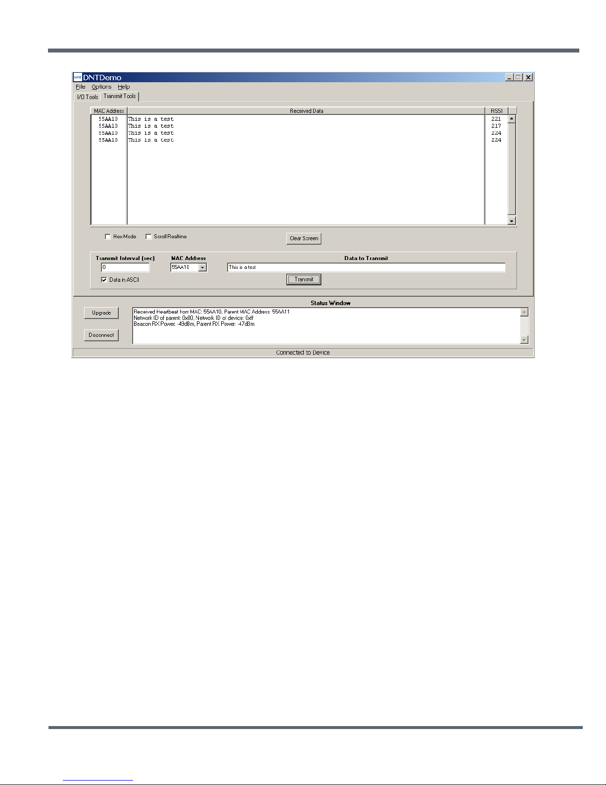
Figure 8.1.1
Pressing the Transmit button on this screen sends the message in the Data to Transmit text box to the
selected MAC Address. Note that the MAC address a remote uses for the base is 0x000000. Data sent to
the local radio is displayed in the Received Data text box. Received data can be displayed as ASCII
(default) or in Hexadecimal format by checking the Hex Mode check box. When the Transmit Interval is
set to zero, Data to Transmit is sent once when the Transmit button is clicked. When the Transmit Interval
is set to a positive number, Pressing the Transmit button once will cause a transmission each transmit
interval (seconds) until the button is pressed again.
©2009-2015 by Murata Electronics N.A., Inc.
DN24G/GI Series User Guide Rev. 2.0 01-09-15 Page 39 of 44 www.murata.com
Page 40
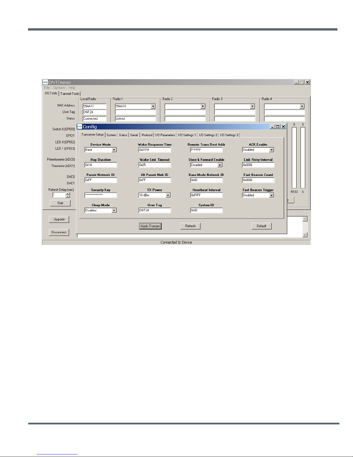
Figure 8.1.2
Returning to the I/O Tools tab, the multi-tab Configuration window for each radio can be accessed by
clicking on its Config button. The data presented on the first four tabs corresponds to configuration
register Banks 0 through 3 as discussed in Section 7.4 above. The remaining tabs do not apply to
DN-24 modem operation.
The Transceiver Setup Tab is shown in Figure 8.1.2 and corresponds to Bank 0. The current values of
each Bank 0 parameter are displayed and can be updated by selecting from the drop-down menus or
entering data from the keyboard, and then pressing the Apply Changes button. Note that data is
displayed and entered in Big-Endian order. The utility program automatically reorders multi-byte data to
and from Little-Endian order when building or interpreting messages.
©2009-2015 by Murata Electronics N.A., Inc.
DN24G/GI Series User Guide Rev. 2.0 01-09-15 Page 40 of 44 www.murata.com
Page 41
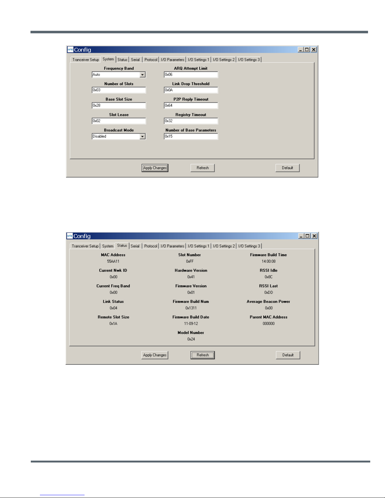
Figure 8.1.3
Figure 8.1.4
Figure 8.1.3 shows the System tab contents, corresponding to Bank 1. The current values of each
parameter are displayed and can be updated by selecting from the drop-down menu or entering data from
the keyboard, and then pressing the Apply Changes button. Note that Bank 1 holds configuration
parameters for the base only except for Br oadc ast Mod e, which applies to both the base and the remotes.
Figure 8.1.4 shows the Status tab contents, corresponding to Bank 2. Note the Status tab contains readonly parameters.
©2009-2015 by Murata Electronics N.A., Inc.
DN24G/GI Series User Guide Rev. 2.0 01-09-15 Page 41 of 44 www.murata.com
Page 42
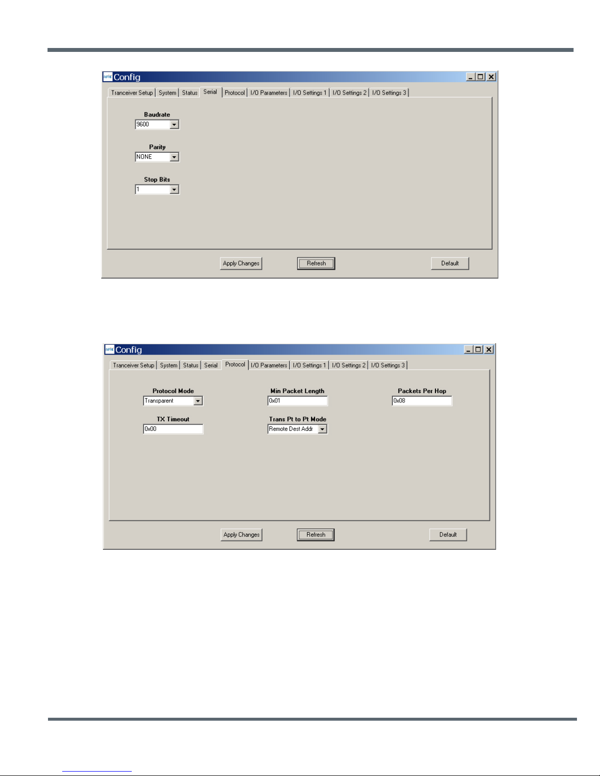
Figure 8.1.5
Figure 8.1.6
Figure 8.1.5 shows the Serial tab contents corresponding to the serial parameters in Bank 3. The values
shown are the defaults for serial port operation.
Figure 8.1.6 shows the Protocol tab contents, corresponding to Bank 4. Transparent serial data
communication is currently chosen.
©2009-2015 by Murata Electronics N.A., Inc.
DN24G/GI Series User Guide Rev. 2.0 01-09-15 Page 42 of 44 www.murata.com
Page 43
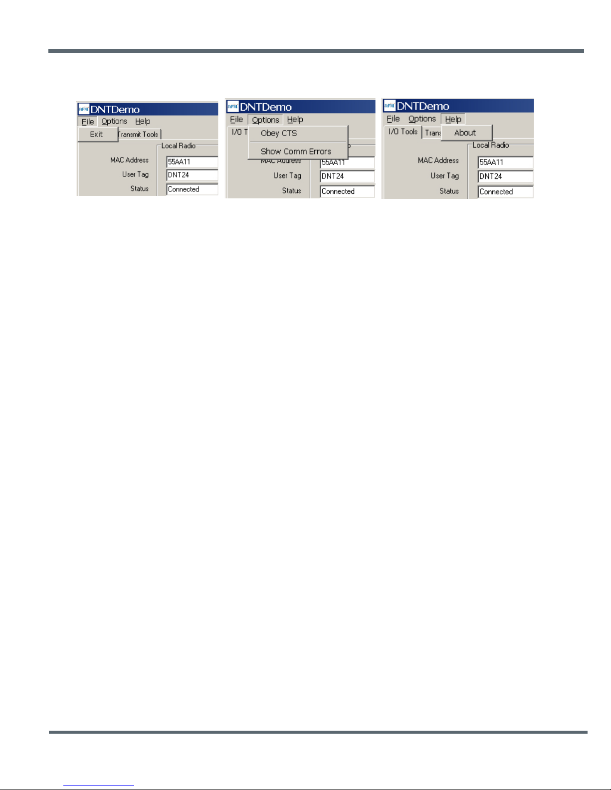
Figure 8.1.7
The Demo Utility File, Options and Help menus are shown in Figure 8.1.7.
©2009-2015 by Murata Electronics N.A., Inc.
DN24G/GI Series User Guide Rev. 2.0 01-09-15 Page 43 of 44 www.murata.com
Page 44

9.0 Warranty
Seller warrants solely to Buyer that the goods delivered hereunder shall be free from defects in materials
and workmanship, when given normal, proper and intended usage, for twelve (12) months from the date
of delivery to Buyer. Seller agrees to repair or replace at its option and without cost to Buyer all defective
goods sold hereunder, provided that Buyer has given Seller written notice of such warranty claim within
such warranty period. All goods returned to Seller for repair or replacement must be sent freight prepaid
to Seller’s plant, provided that Buyer first obtain from Seller a Return Goods Authorization before any
such return. Seller shall have no obligation to make repairs or replacements which are required by normal
wear and tear, or which result, in whole or in part, from catastrophe, fault or negligence of Buyer, or from
improper or unauthorized use of the goods, or use of the goods in a manner for which they are not
designed, or by causes external to the goods such as, but not limited to, power failure. No suit or action
shall be brought against Seller more than twelve (12) months after the related cause of action has
occurred. Buyer has not relied and shall not rely on any oral representation regarding the goods sold
hereunder, and any oral representat io n sha ll not bind Sel ler and sh all not be a part of any warranty.
THE PROVISIONS OF THE FOREGOING WARRANTY ARE IN LIEU OF ANY OTHER WARRANTY,
WHETHER EXPRESS OR IMPLIED, WRITTEN OR ORAL (INCLUDING ANY WARRANTY OR
MERCHANT ABILITY OR FITNESS FOR A PARTICULAR PURPOSE). SELLER’S LIABILITY ARISING
OUT OF THE MANUFACTURE, SALE OR SUPPLYING OF THE GOODS OR THEIR USE OR
DISPOSITION, WHETHER BASED UPON WARRANTY, CONTRACT, TORT OR OTHERWISE, SHALL
NOT EXCEED THE ACTUAL PURCHASE PRICE PAID BY BUYER FOR THE GOODS. IN NO EVENT
SHALL SELLER BE LIABLE TO BUYER OR ANY OTHER PERSON OR ENTITY FOR SPECIAL,
INCIDENTAL OR CONSEQUENTIAL DAMAGES, INCLUDING, BUT NOT LIMITED TO, LOSS OF
PROFITS, LOSS OF DATA OR LOSS OF USE DAMAGES ARISING OUT OF THE MANUFACTURE,
SALE OR SUPPLYING OF THE GOODS. THE FOREGOING WARRANTY EXTENDS TO BUYER
ONLY AND SHALL NOT BE APPLICABLE TO ANY OTHER PERSON OR ENTITY INCLUDING,
WITHOUT LIMITATION, CUSTOMERS OF BUYERS.
Part # M -0024-2002, Rev B
©2009-2015 by Murata Electronics N.A., Inc.
DN24G/GI Series User Guide Rev. 2.0 01-09-15 Page 44 of 44 www.murata.com
 Loading...