

Page 1
DMS-20LCD Series
3½ Digit, LCD Display Digital Panel Voltmeters
FEATURES
N
Lowest cost
N
Lowest power, 2mW
N
Subminiature size:
1.38" x 0.88" x 0.43"
35mm x 22mm x 11mm
N
Large (0.37"/9.4mm), enhanced-contrast LCD display
N
Epoxy-encapsulated, 12-pin DIP
N
Panel or pc-board mountable
N
4 differential input voltage ranges
N
High accuracy, ±1 count (±0.05%)
N
Single +5V supply or 9V battery
N
Low-battery annunciator
N
User-selectable decimal point placement
N
0 to +60°C temperature range
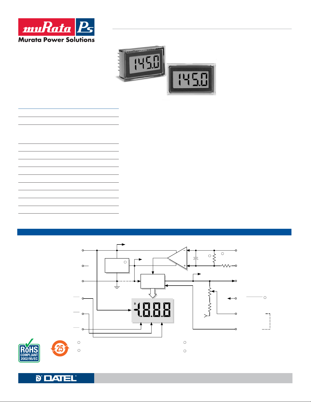
SIMPLIFIED SCHEMATIC DIAGRAM
N.C.
1
2
3
+5V SUPPLY/
+BATTERY
5V RETURN/
–BATTERY
DC/DC
CONVERTER
0 Vdc
DMS-20LCD Series, 3½ Digit, LCD Display, Digital Voltmeters represent the ultimate
combination of low price, low power, small size and high performance in digital meters.
Epoxy encapsulated in a subminiature (1.38” x 0.88” x 0.43”), 12-pin DIP package, these
completely self-contained, fully operational meters offer a combination of ruggedness,
long-term reliability and component-like ease-of-use simply not available in any other
meters.
Incorporating a precision reference and a factory-calibrated, autozeroing A/D converter,
DMS-20LCD meters are extremely accurate (±1 count) and are only slightly larger than
their 0.37"/9.4mm, enhanced-contrast, LCD displays. All models incorporate a built-in
bezel and are easily mounted in either panels or pc boards. Both backlit and non-backlit
versions are available.
DMS-20LCD meters have 4 differential input voltage ranges (±200mV, ±2V, ±20V and
±200V) and a user-friendly input structure. Input impedance is a minimum 800k7. CMRR
is typically 86dB with a CMV of ±2V. Non-inverting inputs are overvoltage protected to
±100V (±250V for the ±200V input model).
All DMS-20LCD meters operate from a single +5V supply (drawing 400μA) or a single
+9V supply/battery (drawing 230μA). All models have a low-battery ("B") annunciator and
feature autopolarity changeover and overrange indication.
Also available is an application/evaluation board (DMS-EB2) that plugs directly onto the
back of any DMS-20LCD allowing direct inputs for common applications such as 4-20mA
inputs, zero/gain adjust, decimal point location, and input voltage dividing.
+5V
3
J1
–5V
A/D
CONVERTER
V+
2
+2.0V
z
R2
0.01μF
V–
1
R1
909k
12
(–) INPUT LO
11
(+) INPUT HI
10
ANALOG
COMMON
For full details go to
www.murata-ps.com/rohs
4
DP 3
5
DP 2
6
DP 1
1
R2 is not used on ±200mV (-0) models or ±2V (-1) models.
R2 = 100k on ±20V (-2) models and 9.1k on ±200V (-3) model s.
2
Only used on ±200mV (-0) and ±2V (-1) models.
DATA
www.murata-ps.com Technical enquiries email: [email protected], tel: +1 508 339 3000
9
N.C./BACKLIGHT
8
+5V
3
DC/DC converter is not used on 9V-powered models,
J1 is connected.
4
Used on backlit models only.
N.C. for non-backlit models.
REFERENCE OUT
7
REFERENCE IN
MPM_DMS20lcd.B03 Page 1 of 6
4
Page 2
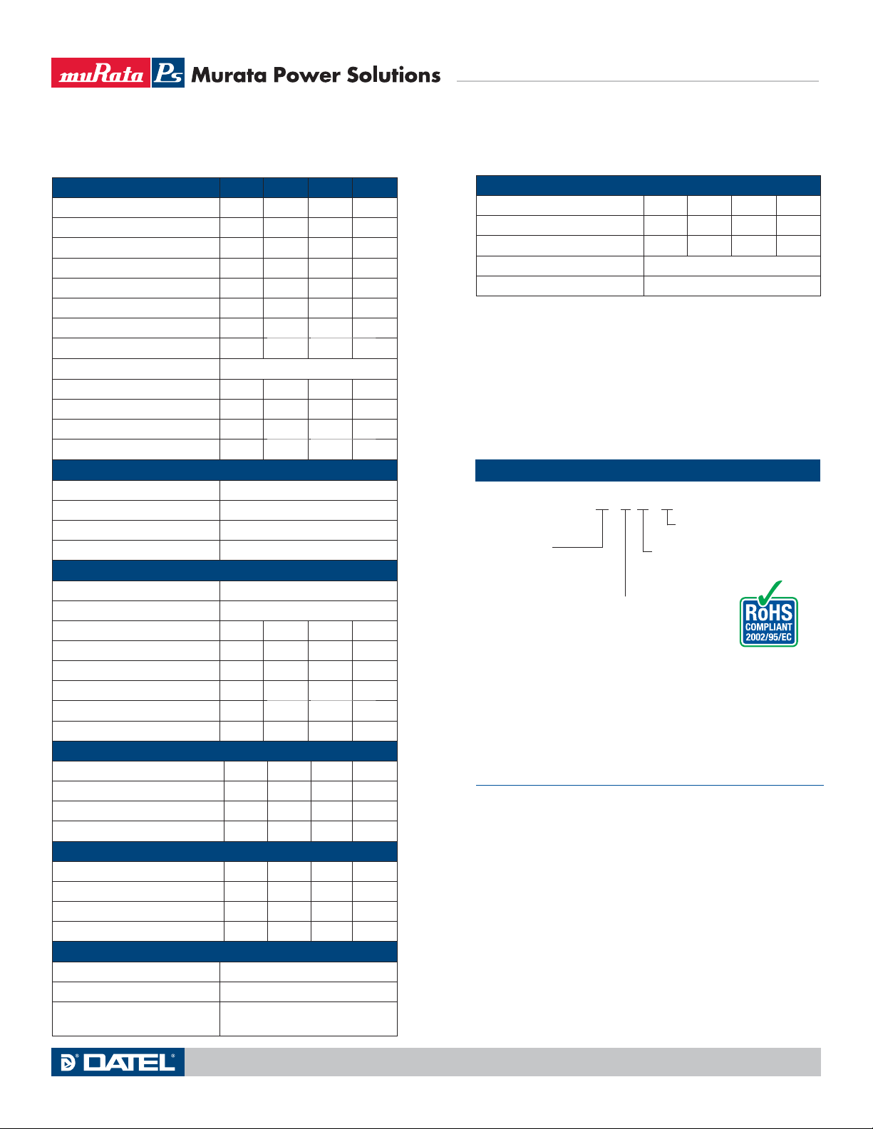
Performance/Functional Specifications
Typical at TA = +25°C and supply voltage = +5V (using the single-ended input
circuit) or +9V (using the differential input circuit), unless otherwise noted.
Analog Inputs Min. Typ. Max. Units
Full Scale Input Range:
DMS-20LCD-0 – ±200 – mV
DMS-20LCD-1 – ±2 – Volts
DMS-20LCD-2 – ±20 – Volts
DMS-20LCD-3 – ±200 – Volts
Input Impedence: –
DMS-20LCD-0, -1 100 1000 –
DMS-20LCD-2, -3 0.8 1 –
Overvoltage Protection ~
DMS-20LCD-0, -1, -2 – – ±100 Volts
DMS-20LCD-3 – – ±250 Volts
Common Mode Voltage Range – – ±2 Volts
CMRR (dc to 60Hz) – 86 – dB
Control Inputs
Decimal Pt. Placement (Pins 4-6) Tie to pin 3 to activate
Functionality Tie to pin 3 to activate
Logic Compatibility TTL (on 5V-powered models)
Backlight (Pin 9) Tie to pin 3 to turn on backlight
Performance
Sampling Rate 2.5 reading per second
Accuracy (1 minute warm-up):
DMS-20PC-0 (Vin = +0.19V) – ±1 ±2 Counts
DMS-20PC-1 (Vin = +1.9V) – ±1 ±2 Counts
DMS-20PC-2 (Vin = +19V) – ±2 ±3 Counts
DMS-20PC-3 (Vin = +190V) – ±2 ±3 Counts
Zero Reading (Vin = 0 Volts) “–001” “000” “001”
Temperature Drift (0 = +60°C) – ±0.2 ±0.4 Cnts/°C
Power Supply Requirements (5V Models)
Supply Voltage +4.75 +5.00 +5.25 Volts
Supply Current:
Standard Models – +400 +650 μA
Backlit Models – +35 +50 mA
Power Supply Requirements (9V Models)
Supply Voltage +7.5 +9.0 +14.0 Volts
Supply Current:
Standard Models – +230 +350 μA
Backlit Models – +35 +50 mA
Display
Display Type and Size 3½ digit, 0.37"/9.4mm high LCD
Polarity Indication Autopolarity ("–" for negative Vin)
Overrange Indication "–1_ __ " for negative Vin
"1_ __ " for positive Vin
M7
M7
DMS-20LCD Series
3½ Digit, LCD Display Digital Panel Voltmeters
Physical/Environmental
Operating Temperature 0 – +60 °C
Storage Temperature –20 – +75 °C
Humidity (non-condensing) 0–95%
Case Material Polycarbonate
Weight 0.4 ounces (11 grams)
~ Applies for transient or continuous overvoltages applied to (+) INPUT HI
(pin 11) with (–) INPUT LO (pin 12) properly connected. Pin 12 is not
overvoltage
protected (see Figure 1). Voltages applied to pin 12 should not exceed the
supply voltage.
Listed spec applies to 5V-powered models only. For 9V-powered models, both
(–) INPUT LO (pin 12) and (+) INPUT HIGH (pin 11) must always be at least
1.5V above –BATTERY (pin 3) and at least 1.5V below +BATTERY (pin 1).
See Technical Notes.
Ordering Information
DMS-20LCD - 1 - 5 - C
Add -C for RoHS
Input Range:
0 = ±200mV
1 = ±2V
2 = ±20V
3 = ±200V
Accessories:
DMS-20-CP Panel cutout punch
DMS-BZL3-C DMS-20 bezel assembly
DMS-BZL4-C DMS-20 bezel assembly with sealing gasket
DMS-EB2-C Application/evaluation board with standard
MOLEX connector, decimal point solder pads
and attenuation resistor pads.
A panel-mount retaining clip is supplied with each model.
TECHNICAL NOTES
1. REFERENCE OUTPUT (Pin 8) and INPUT (Pin 7): Pin 8 is a precision
reference actively trimmed at the factory. In normal operation, pin 8
must be tied to pin 7 to achieve all listed accuracy and drift specifica-
tions.
2. ANALOG COMMON (Pin 10): This pin is connected to an internal,
low-noise, “relative” ground. It is used in certain differential and “float-
ing” measurements as described in the Applications section of this
data sheet and Ap Note 3 of the DATEL Panel Meter Catalog. Pin 10
should not be connected to pin 3 (5V RETURN/–BATTERY) or to
your system’s analog ground.
3. Decimal Point Placement: The location of the decimal point is user-
selectable, and the decimal point control pins (DP1-DP3) are active low
functions. Select the appropriate decimal point by tying the appropriate
pin (pin 4, 5 or 6) to pin 3 (5V RETURN/–BATTERY). Unused decimal
Leave blank for standard
models.
Add B for backlit models.
Power Source:
5 = +5V
9 = +9V
Technical enquiries email: [email protected], tel: +1 508 339 3000www.murata-ps.com
MPM_DMS20lcd.B03 Page 2 of 6
Page 3
DMS-20LCD Series
3½ Digit, LCD Display Digital Panel Voltmeters
point location pins should be left open. For 5V-powered models, the
decimal location pins are TTL compatible and may be hard wired as
described above or driven with 5V TTL logic gates.
4. BACKLIGHT (Pin 9) Function: Grounding pin 9 (i.e. connecting it to
pin 3) turns on the backlighting LED’s. For non-backlit models, pin 9
has no internal connection. All backlit models include internal current-
limiting resistors. With nominal +5V or 9V supplies, backlit devices
typically draw 35mA of supply current. The current drawn by the back-
light (and therefore the current drawn by the meter) can be reduced by
installing a 1/4 Watt resistor between pins 3 and 9. The brightness of
the meter will be reduced proportionately.
9V-powered backlit models function with supply voltages up to +14V,
however, activating the backlight with voltages greater than 9.2V can
damage the meter. Therefore, a 1/4 Watt series resistor must be
installed between pins 3 and 9 in these situations. The value of the
series resistor is determined using the following formula:
R
Series = Ohms
+BATTERY – 9.2V
0.035
Example: If +BATTERY (pin 1 with respect to pin 3) is +12.6V,
RSeries = Ohms
+12.6 – 9.2V
0.035
8. Suggested Mating Connectors:
Panel mounted:
Connector housing DATEL P/N 4320-01069-0
Terminal type DATEL P/N 4400-01032-0
Crimping tool DATEL P/N 39-2099000
Wire size 22 to 26 AWG
Insulation diameter 0.062” (1.57mm) maximum
Stripping length 0.100 to 0.125” (2.54 to 3.17mm)
Board mounted:
Socket DATEL P/N 4320-01074-0
APPLICATIONS
DMS-20LCD meters are available in either 5V-powered or 9V-powered
models. 9V devices operate directly from 7.5V to 14V supplies (usually
batteries) without the need for external voltage regulators. 9V devices,
however, can not be used to measure voltages referenced to the negative
battery terminal (pin 3) because the minus input to the meter (pin 12, (–)
INPUT LO) must always be at least 1.5V above pin 3. 9V-powered meters
can only be used to make differential and not single-ended measurements.
5V-powered devices operate from any well-regulated +5V supply and will
accurately measure voltages both above and below pin 3 (5V RETURN) in
either single-ended or differential configurations.
RSeries = 97 Ohms
5. Low Battery Annunciator: The “B” annunciator in the upper left-hand
corner of the display turns on when the supply voltage for 5V-powered
models falls below approximately +3.7V, or when the supply voltage for
9V-powered models falls below approximately 7.2V. However, the low-
battery annunciator’s turn-on threshold can vary significantly from unit-
to-unit: as low as 2.7V for 5V-powered meters, and as low as 5.4V for
9V-powered models. Applications that use the LOW BAT annunciator
must be fully tested by the user, using a combination of low supply volt-
ages and the input signal’s minimum and maximum levels, to ensure
that all display readings are valid as long as the LOW BAT annunciator
remains off.
6. Gain Adjust: There is a gain-adjust potentiometer on the back of each
meter. It has approximately ±50 counts (±2.5%) range of adjustment.
Since these devices essentially have no zero/offset errors, a gain
adjustment is effectively an overall accuracy adjustment. Though they
may be performed at any point (except zero), accuracy adjustments
are most effective when performed with higher level input signals. The
circuit shown in Figure 9 provides ±10% range of adjustment.
7. Soldering Methods: All models in the DMS-20LCD Series easily
withstand most common wave soldering operations. We recom-
mend, however, that you evaluate the effects your particular soldering
techniques may have on the meter’s plastic case and high-precision
electrical performance. We recommend the use of no-clean solders.
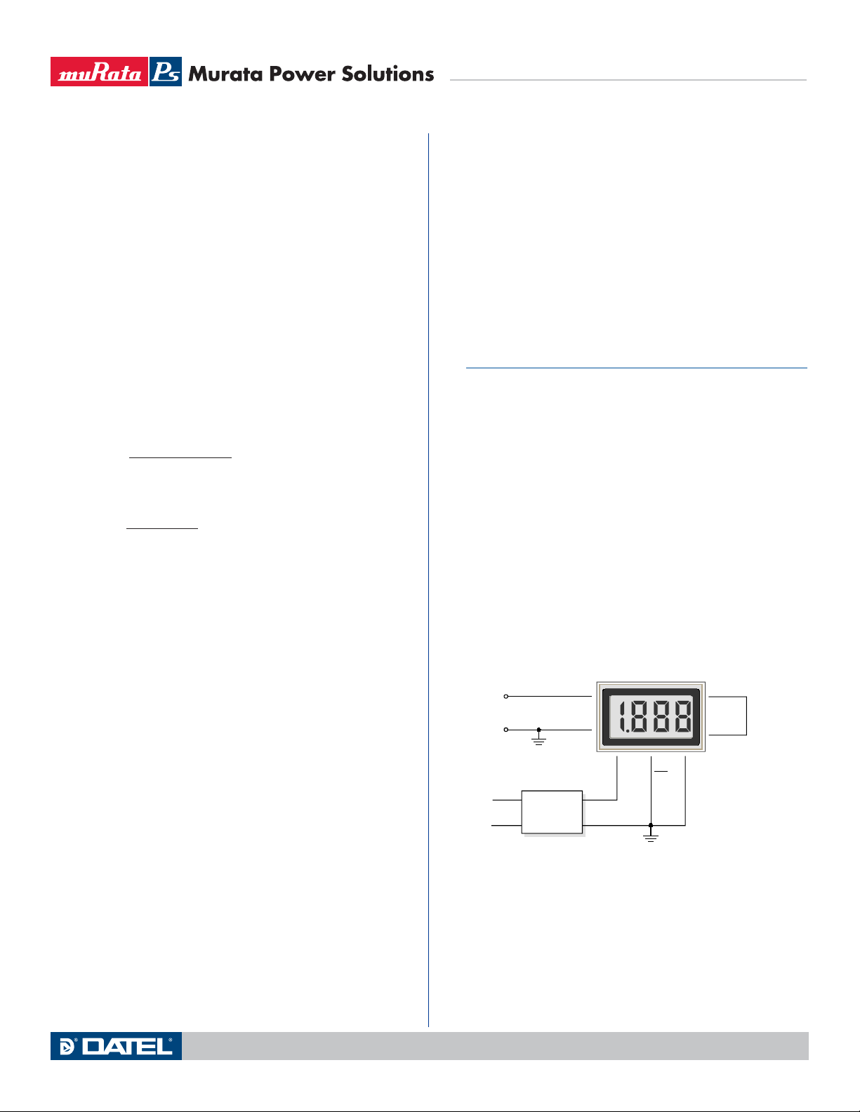
1. Single-Ended Input Configurations: True single-ended measure-
ments can only be made with 5V-powered meters. The circuit of Figure
2 avoids problems normally associated with ground-loop currents.
Separate ground runs should be used for 5V RETURN (pin 3) and (–)
INPUT LO (pin 12).
DMS-20LCD-1-5
+
V
–
120 VAC
11
(+) IN HI
IN
12
(–) IN LO
1
+5V SUP
DATEL
UPA-5/500
AC to DC Converter
Figure 2. Single-Ended Input Configuration
(5V-Powered Models)
6
DP1
3
5V RET
8
REF OUT
7
REF IN
Technical enquiries email: [email protected], tel: +1 508 339 3000www.murata-ps.com
MPM_DMS20lcd.B03 Page 3 of 6
Page 4
APPLICATIONS
DMS-20LCD Series
3½ Digit, LCD Display Digital Panel Voltmeters
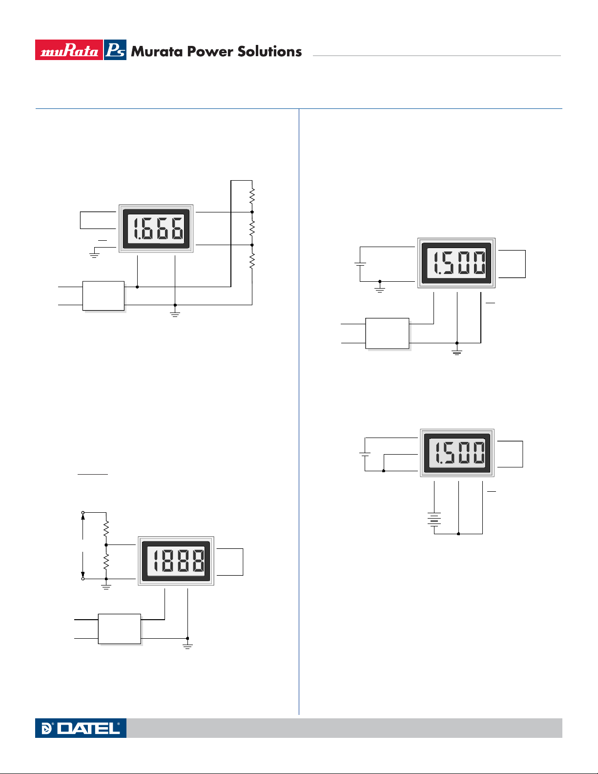
2. Differential Input Configurations: Differential measurements can be
made with either 5V-powered or 9V-powered meters. Figure 3, though
not a practical real-world application, uses a voltage divider to demon-
strate the concept of a differential input signal. Be careful not to exceed
the ±2V common mode voltage limitation for 5V powered meters.
R1
1k
R2
1k
R3
1k
120 VAC
DMS-20LCD-1-5
8
REF OUT
REF IN
7
DP1
6
+5V SUP
DATEL
UPA-5/500
AC to DC Converter
1
3
5V RET
Figure 3. Differential Input Configuration
(5V-Powered Models)
11
(+) IN HI
12
(–) IN LO
3. Engineering Scaling: For measuring voltages greater than the full
scale input range of a given meter, the input signal must be attenuated.
A simple voltage divider (similar to that shown in Figure 4) will scale
the input to within the range of the selected meter. R1 and R2 should
be precision, ±1%, metal-film resistors with absolute TCR’s less than
50ppm/°C. See Ap Note 4 for more information on engineering scaling.
50k7 < R1 + R2 < 10M7
R2
x VIN = Reading
R1 + R2
+
R1
IN
V
–
120 VAC
(+) IN HI
R2
(–) IN LO
DATEL
UPA-5/500
AC to DC Converter
Figure 4. Input Attenuation Circuit
DMS-20LCD-1-5
DMS-20LCD-1-9
11
12
1
+5V SUP 5V RET
8
REF OUT
7
REF IN
3
4. Floating Signal Source Measurements: Floating signals can be
measured using the circuits shown in Figures 5 and 6. Figure 5 uses
a 5V-powered meter. Figure 6 uses a 9V-powered meter. Connecting
pin 10 (ANALOG COMMON) to (–) INPUT LO (pin 12) provides the
reference point for the meter’s input.
A “floating” input is a signal that has no galvanic connection to the
meter’s power supply. In the figures below, the 1.5V battery illustrates a
true floating input.
DMS-20LCD-1-5
1.5V
CELL
120 VAC
(+) IN HI
+
–
(–) IN LO
DATEL
UPA-5/500
AC to DC Converter
11
12
13
+5V SUP 5V RET
6
DP1
8
REF OUT
7
REF IN
Figure 5. Floating Input Measurements
(5V-Powered Models)
DMS-20LCD-1-5
1.5V
CELL
11
(+) IN HI
+
–
ANA COMM
(–) IN LO
BATTERY
10
12
9V
1
+ BAT –BAT
3
+
–
6
DP1
8
REF OUT
7
REF IN
Figure 6. Floating Input Measurements
(9V-Powered Models)
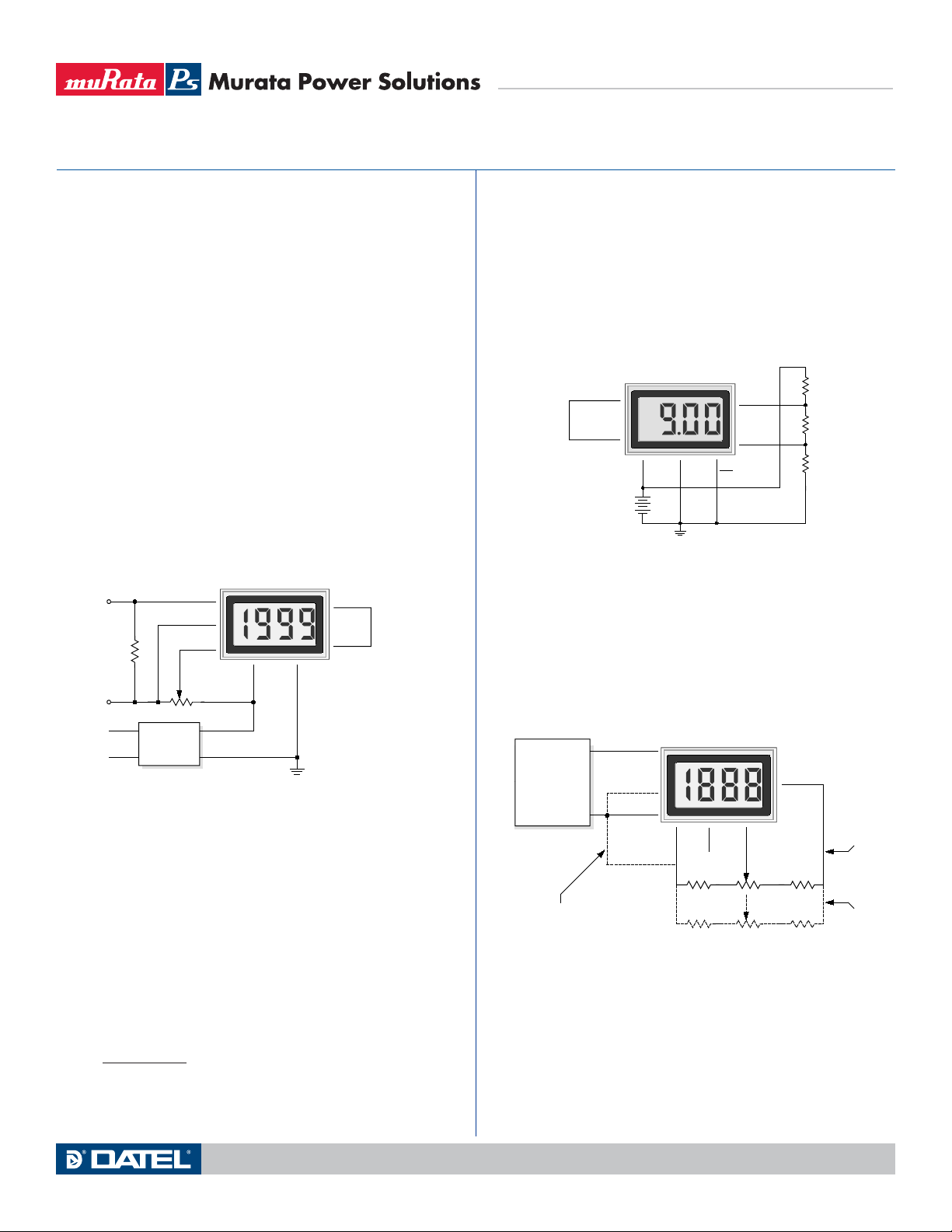
5. Process Control (4-to-20mA) Measurements: In many common
process-control applications, a 4-to-20mA current loop is used to
transmit information. Because DMS-20LCD meters have such high
input impedance, a simple shunt resistor across the meter’s input can
be used to convert the loop current to a voltage. See Figure 7. The
value of the shunt resistor is a function of the scaling requirements of
the particular application and can be calculated using the following
equation:
Technical enquiries email: [email protected], tel: +1 508 339 3000www.murata-ps.com
MPM_DMS20lcd.B03 Page 4 of 6
Page 5
APPLICATIONS
k
k
k
DMS-20LCD Series
3½ Digit, LCD Display Digital Panel Voltmeters
R
Shunt = R1 = VFsr /IFsr
Where: VFsr = Full scale reading (in Volts)
I
Fsr = Relative full scale current (in Amps)
Example: For a meter with a 2V full scale input (1.999 full
scale reading) and a desired full scale display reading of
1000 (with an input of 20mA), VFsr = 1.000 Volts
R
R
Shunt = 1.000V/(0.020 – 0.004)A
Shunt
= 1.000V/0.016A = 62.5 Ohms
To calibrate the circuit of Figure 7, perform the following:
1. With 4mA applied, adjust the 50k7 potentiometer (R2) to
display a reading of "000" (assuming that is the desired
reading).
2. With 20mA applied, adjust the gain-adjust potentiometer on
the back of the meter to display a reading of "1999". For different full
scale readings, alter the value of R
+
R1
4-20mA
–
120 VAC
AC to DC Converter
Figure 7. 4-to-20mA Current Loop Operation
(+) IN HI
ANA COMM
(–) IN LO
R2
50k
DATEL
UPA-5/500
(5V-Powered Models)
Shunt accordingly.
DMS-20LCD-1-5
11
10
12
13
+5V SUP
5V RET
8
REF OUT
7
REF IN
6. Power Supply Monitoring: A popular application for DATEL’s low-
power LCD meters is monitoring the supply voltage in battery-oper-
ated portable equipment. Figure 8 demonstrates how a 9V-powered
DMS-20LCD can be used to monitor its own supply. The meter used
is the DMS-20LCD-1-9. A three-resistor voltage divider is used to
attenuate the battery voltage and also to satisfy the requirement that
the input voltages applied to pins 12 and 11 be at least 1.5 Volts above
and below the battery voltage applied to pins 1 (+BATTERY) and 3
(–BATTERY). The divider should be designed so that 1/10th the bat-
tery voltage falls across the inputs to the meter:
Therefore, the 9V battery voltage appears to the meter inputs as 0.9V.
With the decimal point moved to its DP2 position
(pin 5 tied to pin 3), the meter reads 9.00 Volts.
The circuit can be calibrated by first measuring the actual battery volt-
age with another meter and then adjusting the gain-adjust potentiom-
eter on the back of the DMS-20LCD until a similar reading is obtained.
If possible, the resistors in the divider should be ±1% metal-film types
with TCR’s less than 50ppm/°C.
REF OUT
REF IN
BATTERY
DMS-20LCD-1-9
8
7
1
+BAT
+
9V
–
3
–BAT
DP2
5
Figure 8. Power Supply Monitor
(9V-Powered Models)
11
(+) IN HI
12
(–) IN LO
R1
45.3
R2
10.1
R3
45.3
7. External Gain Adjustment: Connect REFERENCE OUT
(pin 8) to REFERENCE IN (pin 7) for normal, factory calibrated,
operation. Use the circuit shown in Figure 9 for applications needing
external gain adjustment. Calibration is performed with a precise,
near-full-scale, input voltage.
OUT
VOLTAGE
12
CALIBRATOR
COM
For +5V models, tie (–) IN LO to pin 3.
For +9V models, tie (–) IN LO to pin 10
(+) IN HI
5V RET/
–BAT IN
(–) IN LO
Figure 9. External Gain Adjustment
11
12
COMM
3
ANA
10
DMS-20LCD
8
NC
8.06k, 1%
732, 1%
7
REF
IN
2k
200
= 10 to 20 Turns
1
+5V IN/
+BAT IN
17.4k, 1%
24.3k, 1%
Connections
for ±2V, ±20V
and ±200V models
Connections
for ±200mV
models
R2
(R1 + R2 + R3)
= 0.1
Technical enquiries email: [email protected], tel: +1 508 339 3000www.murata-ps.com
MPM_DMS20lcd.B03 Page 5 of 6
Page 6
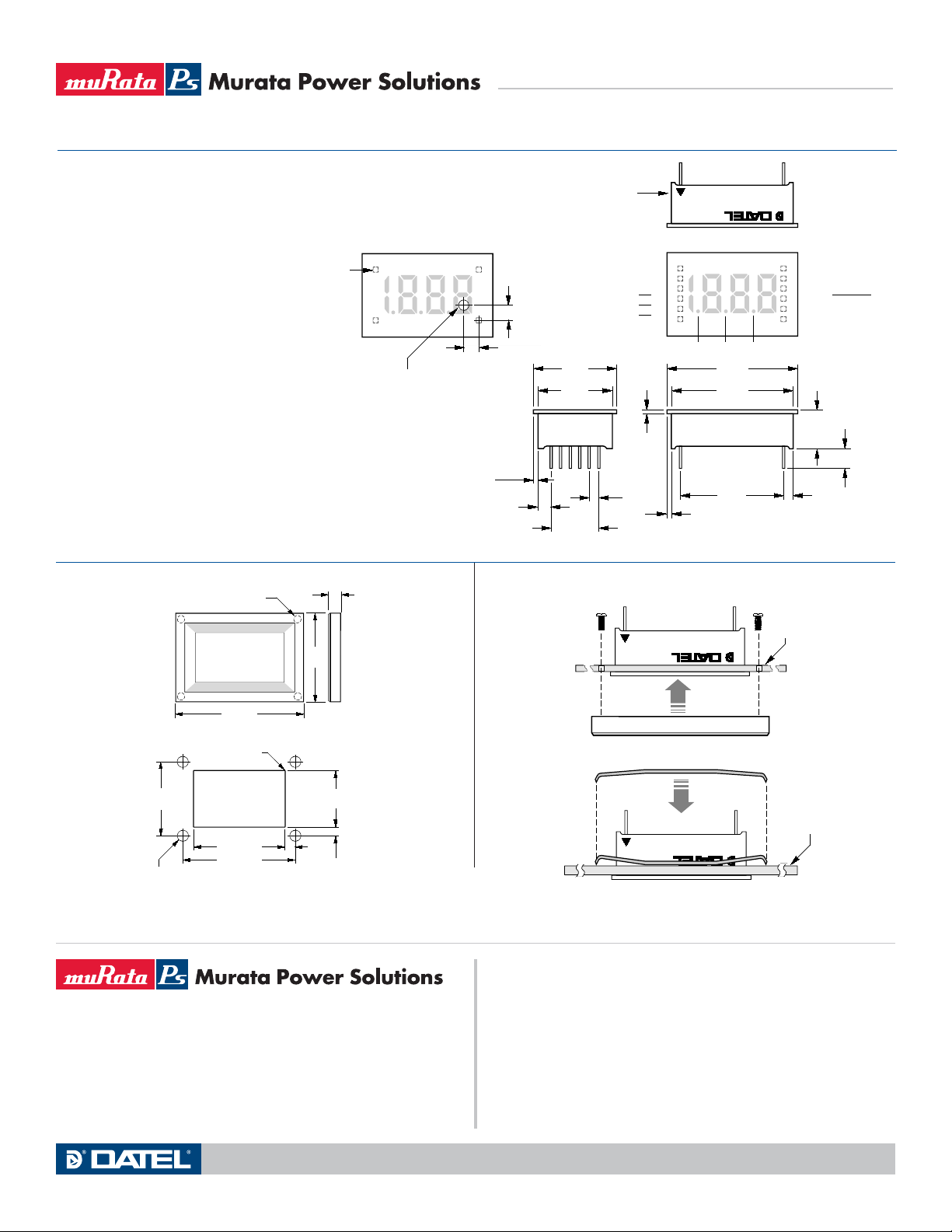
MECHANICAL SPECIFICATIONS
OPTIONAL BEZEL (DMS-BZL3 and DMS-BZL4)
L
MECHANICAL DIMENSIONS: Inches (mm)
TOLERANCES: 2 PL DEC ±0.02 (±0.51)
3 PL DEC ±0.010 (±0.254)
LEAD DIMENSIONS: 0.025 (0.635) x 0.025 (0.635) NOMINAL
RECOMMENDED PC BOARD FINISHED HOLE DIAMETER:
0.042 ±0.003 (1.067 ±0.076)
CALIBRATION POTENTIOMETER HOLE LOCATION
PIN 1
0.125 (3.175) DIAMETER
(USE ONLY WHEN PC
BOARD MOUNTING)
0.160
(4.06)
0.040
(1.02)
0.160
(4.06)
0.15
(3.8)
TYP.
BEZEL INSTALLATION AND RECOMMENDED DRILL AND PANEL CUTOUT
DMS-20LCD Series
3½ Digit, LCD Display Digital Panel Voltmeters
PIN #1
IDENTIFIER
+5V SUPPLY/ +BATTERY
5V RETURN/ –BATTERY
0.88
(22.3)
0.80
(20.3)
0.10
(2.5)
TYP.
0.50
(12.7)
N.C.
DP3
DP2
DP1
0.040
(1.02)
1
2
3
4
5
6
MADE IN USA
®®
FRONT VIEW
DP1 DP2 DP3
1.38
(35.1)
1.30
(33.0)
1.10
(27.9)
0.040
(1.02)
DMS-20LCD-X-XX
12
(–) INPUT LO
11
(+) INPUT HI
10
ANALOG COMMON
9
N.C./BACKLIGHT
8
REFERENCE OUT
7
REFERENCE IN
0.425
(10.80)
0.25
(6.4) TYP.
0.10
(2.5)
TYP.
0.187
(4.75)
1.280
(32.51)
0.145
(3.68)
0.838
(21.29)
0.116
(2.95)
FRONT VIEW
RECOMMENDED DRILL AND PANEL CUTOUT DIMENSIONS
1.07
(27.18)
0.093 (2.362) DIAMETER (4 REQUIRED)
ONLY WHEN USING OPTIONAL BEZEL ASSEMBLY
#2-56 INSERT
0.156 (3.96) DEEP
1.826 (46.38)
INTERNAL CORNER RADII:
0.032 (0.81) MAX.
1.336 (33.93)
1.626 (41.30)
Murata Power Solutions, Inc.
11 Cabot Boulevard, Mansfield, MA 02048-1151 U.S.A.
Tel: (508) 339-3000 (800) 233-2765 Fax: (508) 339-6356
www.murata-ps.com email: [email protected] ISO 9001 and 14001 REGISTERED
Murata Power Solutions, Inc. makes no representation that the use of its products in the circuits described herein, or the use of other
technical information contained herein, will not infringe upon existing or future patent rights. The descriptions contained herein do not imply
the granting of licenses to make, use, or sell equipment constructed in accordance therewith. Specifications are subject to change without
notice. © 2008 Murata Power Solutions, Inc.
10/23/08
BEZEL INSTALLATION
PANEL
®®
BEZEL
RETAINING CLIP INSTALLATION
PANE
®®
USA: Mansfield (MA), Tel: (508) 339-3000, email: [email protected]
Canada: Toronto, Tel: (866) 740-1232, email: [email protected]
UK: Milton Keynes, Tel: +44 (0)1908 615232, email: [email protected]
France: Montigny Le Bretonneux, Tel: +33 (0)1 34 60 01 01, email: [email protected]
Germany: München, Tel: +49 (0)89-544334-0, email: [email protected]
Japan: Tokyo, Tel: 3-3779-1031, email: [email protected]
Osaka, Tel: 6-6354-2025, email: [email protected]
Guangzhou, Tel: +86 208 221 8066, email: [email protected]
Singapore: Parkway Centre, Tel: +65 6348 9096, email: [email protected]
Technical enquiries email: [email protected], tel: +1 508 339 3000www.murata-ps.com
MPM_DMS20lcd.B03 Page 6 of 6
 Loading...