

Murana WSG112 General Instruction Manual
Model / Modèle
:
WSG112
28 inch 357 cc Gas Snowthrower
General Instruction Manual (p.2)
Soufeuse à essence de 28po, 357 cc
Manuel d’instruction général (p.26)
QUESTIONS? 1 (877) 840-0840
Our Customer Service staff are ready to provide
assistance. If a part is damaged or missing, replacement
parts can be shipped from our facility.
For immediate help with assembly, or for additional
product information, call our North American toll-free
number: 1 (877) 840-0840.C
SAVE THIS MANUAL
You will need this manual for safety instructions, operating procedures, and warranty.
Put it and the original sales invoice in a safe, dry place for future reference.
CONSERVEZ CE GUIDE
Vous aurez besoin de ce guide pour les instructions de sécurité, les procédures d’utilisation et la garantie.
Conservez-le dans un endroit sûr et sec pour référence future.
Notre personnel du service à la clientèle sera prêt à
fournir assistance. Si une pièce est endommagée ou
manquante, des remplacements seront expédiés de notre
usine.
Pour de l’aide immédiate avec l’assemblage, ou pour des
informations additionnelles sur le produit, appeller notre
numéro sans frais nord-américain : 1 (877) 840-0840.C
WSG112 v.090220
TABLE OF CONTENTS
Important Safe Operating Practices .............................................................. p.2
Assembly Instructions ...................................................................................p.5
Specications ............................................................................................
Functional Description ................................................................................... p.8
Operating Procedures ................................................................................... p.10
Adjustment ............................................................................................
Maintenance ............................................................................................
Servicing .............................................................................................
ENGLISH
Warranty ............................................................................................
Troubleshooting ............................................................................................
Parts List ............................................................................................
Schematic Drawings ......................................................................................p.23
.... p.8
........ p.14
......p.16
...........p.17
............p.18
.p.19
...........p.20
IMPORTANT SAFE OPERATING PRACTICES
IMPORTANT: Read safety rules and instructions carefully before operating this
equipment.
WARNING: This unit is equipped with an internal combustion engine and should
not be used on or near any unimproved forest-covered, brush-covered or grasscovered ground unless the engine’s exhaust system is equipped with a spark
arrester meeting applicable local or state laws (if any). If a spark arrester is used,
it should be maintained in effective working order by operator.
!
!
WARNING: This symbol points out important safety instructions which, if not
followed could endanger the personal safety and /or property and others.
Read and follow all instructions in this manual before attempting to operate this
machine. Failure to comply with these instructions may result in personal injury
When you see this symbol—heed its warning.
WARNING: Engine Exhaust. Some of its constituents, and certain machine
components contain or emit chemicals that may cause cancer, birth defects,
other reproductive harm.
DANGER: This machine was built to be operated according to the rules for safe
operation in this manual. As with any type of power equipment, carelessness
or error on the part of the operator can result in serious injury .This machine
is capable of amputating hands and feet and of throwing objects. Failure to
observe the following safety instructions could result in serious injury or death .
To use this tool properly, you must observe the safety regulations, the assembly
instructions and the operating instructions to be found in this manual. All persons
who use and service the machine must be informed about its potential hazards
and must be acquainted with this manual. Children should be supervised at all
times if they are in the area in which the tool is being used. It is also imperative that
you observe the accident prevention regulations in force in your area. The same
applies for general rules of occupational health and safety.
WARNING: When using gasoline powered equipment, basic safety precautions,
including the following, should always be followed to reduce the risk of serious
personal injury and/or damage to the unit. Read all these warnings and
instructions before operating this product. Save this Instruction Manual for
future reference.
1.
Read, understand and follow all instructions on the machine and in the
manual(s) before attempting to assemble and operate. Keep this manual in a
safe place for future and regular reference and for ordering replacement parts.
Be familiar with all controls and their proper operation. Know how to stop the
2.
machine and disengage them quickly.
2 WSG112
!
!
!
!

IMPORTANT SAFE OPERATING PRACTICES
3. Never allow children under 14 years of age to operate this machine. Children
14 years old and over should read and understand the operating instructions
and safety rules in this manual and should be trained and supervised by a
parent.
4. Never allow anyone to operate this machine without proper instruction.
5. Thrown objects can cause serious personal injury. Plan your snow-throwing
pattern to avoid discharge of material toward roads, bystanders and the like.
6. Keep bystanders, helpers, pets and children at least 25 metres (75 feet) from
the machine while it is in operation. Stop machine if anyone enters the area .
7. Exercise caution to avoid slipping or falling, especially when operating in
reverse.
PREPARATION
1. Thoroughly inspect the area where the equipment is to be used. Remove all
foreign objects such as doormats, newspapers, sleds, boards, wires, and other
items, which could be tripped over or thrown by the auger/impeller.
2. Always wear safety glasses or eye shields to protect your eyes during
operation and while performing adjustments or repairs. Thrown objects which
ricochet can cause serious injury to the eyes.
3. Do not operate without wearing adequate winter outer garments. Do not wear
jewelery, long scarves or other loose clothing which could become entangled in
moving parts. Wear footwear which will improve footing on slippery surfaces.
4. Use a grounded three-wire extension cord and receptacle for all units with
electric-start engines.
5. Adjust the collector housing height to clear gravel or crushed rock surfaces.
6. Disengage all clutch levers before starting the engine.
7. Never attempt to make any adjustments while engine is running, except where
specically recommended in the operator’s manual(s).
8. Allow the engine and machine to adjust to outdoor temperature before starting
to clear snow.
9. To avoid personal injury or property damage, use extreme care in handing
gasoline. Gasoline is extremely ammable and the vapors are explosive.
Serious personal injury can occur, when gasoline is spilled on yourself or your
clothes, which can ignite. Wash your skin and change clothes immediately.
a. Use only an approved gasoline container.
b. Extinguish all cigarettes, cigars, pipes and other sources of ignition.
c. Never fuel the machine indoors.
d. Never remove gas cap or add fuel while the engine is hot or running.
e. Allow engine to cool at least two minutes before refueling.
f. Never over-ll the fuel tank. Fill tank to no higher than 1.25 cm (1/2 inch)
below bottom of ller neck to provide space for fuel expansion.
g. Replace gasoline cap and tighten securely.
h. If gasoline is spilled, wipe it off the engine and equipment. Move machine
to another area. Wait 5 minutes before starting the engine.
i. Never store the machine or fuel container inside where there is open
ame, spark, or pilot light (e.g. furnace, water, heater, space heater,
clothes dryer, etc.)
j. Allow machine to cool at least 5 minutes before storing.
ENGLISH
OPERATION
1. Do not put hands or feet near rotating parts, in the auger/impeller housing, or
the chute assembly. Contact with the rotating parts can amputate hands and
feet.
2. The auger/impeller control is a safety device. Never bypass its operation. Doing
so makes the machine unsafe and may cause personal injury.
3. The controls must operate easily in both directions and automatically return to
the disengaged position when released.
4. Never operate with a missing or damaged chute assembly. Keep all safety
devices in place and working.
5. Never run an engine indoors or in a poorly ventilated area. Engine exhaust
contains carbon monoxide, an odorless and deadly gas.
v.090220 3

IMPORTANT SAFE OPERATING PRACTICES
6. Do not operate machine while under the inuence of alcohol or drugs.
7. Mufer and engine become hot and can cause bums. Do not touch.
8. Exercise extreme caution when operating on or crossing a gravel surface.
9. Stay alert for hidden hazards or trafc.
10. Exercise caution when changing direction and while operating on slopes.
11. Plan your snow-throwing pattern to avoid discharge towards windows, walls,
cars, etc., thus avoiding possible property damage or personal inquiry caused
by a ricochet.
12. Never direct discharge at children, bystanders, and pets nor allow anyone in
front of the machine.
ENGLISH
13. Do not overload machine capacity by attempting to clear snow at too fast a
rate.
14. Never operate this machine without good visibility or light. Always be sure of
your footing and keep a rm hold on the handles. Walk. Never run.
15. Disengage power to the auger/impeller when transporting or not in use.
16. Never operate machine at high transport speeds on slippery surfaces. Look
down and behind and use care when in reverse.
17. If the machine should start to vibrate abnormally, stop the engine, disconnect
the spark plug wire, and ground it against the engine. Inspect thoroughly for
damage.
18. Disengage all controls and stop the engine before you leave the operator’s
position (behind the handles). Wait until the auger/impeller comes to
a complete stop before unclogging the chute assembly or making any
adjustments.
19. Never put your hand in the discharge or collector openings. Always use the
clean-out tool provided to unclog the discharge opening. Do not unclog chute
assembly while the engine is running. Shut off the engine and remain behind
handles until all moving parts have stopped before unclogging.
20. Use only attachments and accessories approved by the manufacturer (e.g.
wheel weights, tire chains, cabs etc.). If situations occur which are not covered
in this manual, use care and good judgment. Contact us at 1-877-840-0840 for
advice.
MAINTENANCE AND STORAGE
1. Never tamper with safety devices. Check their proper operation regularly. Refer
to the maintenance and adjustment sections of this manual.
2. Before cleaning, repairing, or inspecting the machine disengage all controls
and stop the engine. Wait until the auger/impeller comes to a complete
stop. Disconnect the spark wire and ground it against the engine to prevent
unintended starting.
3. Check bolts and screws for proper tightness at frequent intervals to keep the
machine in safe working condition. Also, visually inspect machine for any
damage.
4. Do not change the engine governor setting or over-speed the engine. The
governor controls the maximum safe operating speed of the engine.
5. Snowthrower shave plates and skid shoes are subject to wear and damage.
For your safety protection, frequently check all components and replace with
original equipment manufacturer’s (OEM) parts only. Use of parts which do not
meet the original equipment specications may lead to improper performance
and compromise safety!
6. Check clutch controls periodically to verify they engage and disengage
properly, and adjust them if necessary. Refer to the adjustment section in the
operator’s manual for instructions.
7. Maintain or replace safety and instruction labels, as necessary.
8. Observe proper disposal laws and regulations for gas, oil, etc. to protect the
environment.
9.
Prior to storing, run machine a few minutes to clear snow from machine and
prevent freeze up of auger/impeller.
10. Never store the machine or fuel container inside where there is a possibility of
open ame or spark.
11. Always refer to the operator’s manual for proper instructions regarding offseason storage.
4 WSG112

IMPORTANT SAFE OPERATING PRACTICES
WARNING: Restrict the use of this power machine to persons who read,
!
!
!
understand and follow the warnings and instructions in this manual and on the
machine.
WARNING: The warnings, cautions, and instructions detailed in this manual
cannot cover all possible conditions and situations that occur. It must be
understood by the operator that COMMON SENSE AND CAUTION ARE
FACTORS that cannot be built into this product, but MUST BE SUPPLIED BY
THE OPERATOR.
WARNING: DO NOT OPERATE machine until it has been assembled and set
up according to the instructions in “ASSEMBLY INSTRUCTIONS”. Read and
follow all safety rules within this Instruction Manual. Failure to do may result in
serious personal injury.
ENGLISH
ASSEMBLY INSTRUCTIONS
NOTE: Reference to right or left side of the snowthrower is determined from
behind the unit in the operator’s position. The “operator’s position” is dened as
standing directly behind the snowthrower, facing the handle panel.
UNPACKING
1. Remove the master carton from around the gas snowthrower.
2. Set panel aside to avoid tire punctures or personal injury.
3. Remove and discard plastic bag and paper card, if any, that covers unit.
4. Remove any loose parts included with unit (i.e., Operator’s Manual, etc.).
LOOSE PARTS
The augers are secured to the auger shaft with two shear pins (a, g.1) and cotter
pins (b, g.1). If you hit a foreign object or ice jam, the snowthrower is designed so
that the shear pins break rather than the augers. Therefore a spare pair is provided
for your convenience. Store in a safe place until needed.
WARNING: Disconnect the spark plug wire and ground it against the engine to
!
prevent unintentional starting.
ASSEMBLE UPPER AND LOWER HANDLE
1. Remove the lower two plastic knobs, cupped washers and carriage bolts from
each side of the lower handle (c, g.2).
2. Raise the upper handle (e, g.2) assembly until it locks over the lower handle.
3. Secure the upper handle and lower handle with the two plastic knobs (f, g.2),
cupped washers (h, g.5), and carriage bolts (g, g.5) previously removed.
4. Tighten the upper two plastic knobs.
ASSEMBLE DISCHARGE CHUTE
1. Loosen and remove six sets of bolts (ss, g.3), lockwashers (tt, g.3), at
washers (uu, g.3), and hex nuts (ww, g.3) on the discharge chute (C, g.3, &
4) so as to remove three pieces of anges (vv, g.3).
v.090220 5
ASSEMBLY INSTRUCTIONS
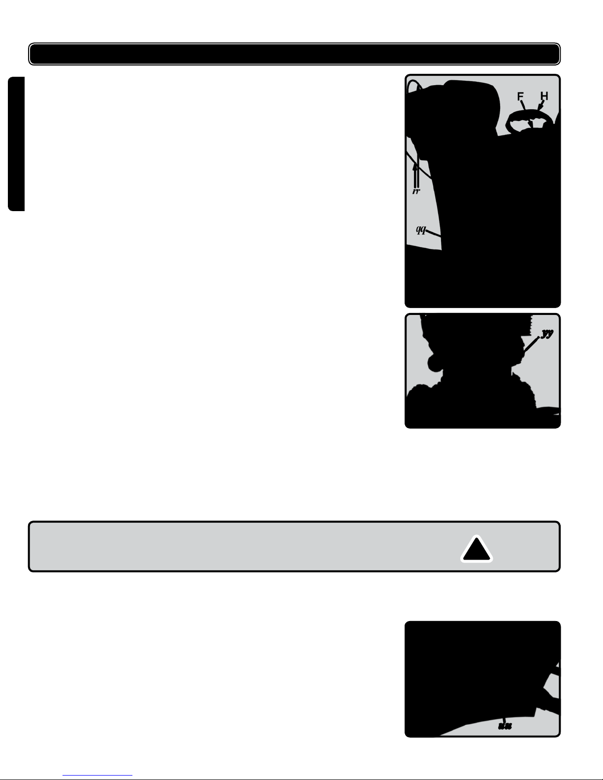
2. Put the discharge chute on the chute adapter (qq, g.4).
3. Locate the anges under the chute adapter, aligning their holes with the holes
on the discharge chute.
4. Fasten six sets of bolts, lockwashers, at washers, and hex nuts previously
removed.
5. If not already assembled, add the two-pronged metal guard (yy, g.5) to the
chute entrance and fasten with bolts as shown.
ENGLISH
ASSEMBLE THE AUGER CONTROL AND DRIVE
CONTROL CABLES
The Auger Control cable (r, g.7) is located at the left side while that for Drive
Control (K, g.7 & 10) is at the right side.
To assemble the cable for Auger Control, slide the cable connector up over the
end of the nut
Follow the same steps to assemble the Drive Control cable.
IMPORTANT: Refer to Auger Control Test and Drive Control and Shift Lever
prior to operating your snow thrower. Read and follow all instructions carefully
and perform all adjustments to verify your snow thrower is operating safely and
properly.
ASSEMBLE THE SHIFT ROD
1. Remove the hairpin clip and at washer from the lower shift rod (ff, g.7&17).
2. Slide the lower shift rod through the shift arm (hh, g.7&17).
3. Check the upper end of the shift rod under the control panel. If not already
assembled, be sure there is a lock nut (uu, g.6) snugged up tight against the
rod attachment.
4. Insert the at washer removed earlier
5. Secure with the hairpin clip removed earlier.
6. Remove the hairpin clip and at washer from the upper shift rod (dd, g.7&17).
7. Slide the shift rod connector (gg, g.7&17) down over the upper end of the
lower shift rod.
8. Tap the connector until it locks on the lower shift rod.
9. Insert the at washer removed earlier
10. Secure with the hairpin clip removed earlier.
6 WSG112
!
ASSEMBLY INSTRUCTIONS
NOTE: If the connector is not properly assembled, the shift rod will pivot and you
will not be able to change speeds or change directions.
ENGLISH
ATTACH CHUTE DIRECTIONAL CONTROL
1. Remove the hairpin clip from the upper gimbal (pp, g.7).
2. Slide the upper chute rod (m, g.7) through the upper chute rod bracket and
into the gimbal. A pair of pliers may help in this job.
3. Align the two holes on upper chute rod and on the gimbal and insert the hairpin
clip removed earlier, through these holes.
4. Check that the lower gimbal and worm gear are set up to engage the chute
directional control teeth (as shown in g.8).
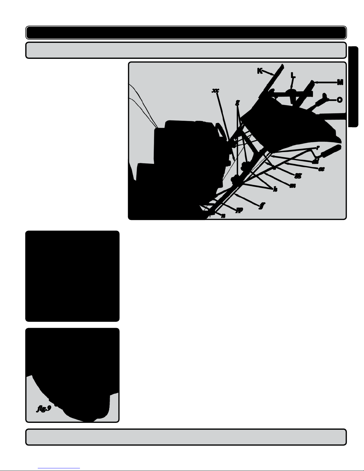
ASSEMBLE SKID SHOES
1. Skid shoes are separately packed. Locate the skid shoes (U, g.9) in the
carton.
2. Loosen the two nuts and washers on the skid shoe.
3. Assemble one skid shoe on one side of the auger housing (B, g.9), put on the
washers and secure the nuts with wrench.
4. Assemble the second shoe on the other side of the auger housing, following
same steps.
NOTE: Refer to SKID SHOE ADJUSTMENT for proper position of snow removal
on different surfaces.
v.090220 7

SPECIFICATIONS
2 stage snow clearance
Motor: 27-degree inclined single cylinder, four-stroke gasoline engine
Bore x stroke: 83 x 64
Displacement: 357 cc (21.8 cu.in.)
AC electric start and recoil (pull) start
CDI (capacitive discharge) ignition
Max. snow throwing distance: 10 m (32.8 ft.)
Max. snow clearing width: 71 cm (28”)
ENGLISH
Max. snow clearing depth: 53 cm (21”)
Fuel capacity: 5 L (1.3 US gal.) unleaded gasoline
Normal lubricant: SAE 5W30 motor oil
Oil reservoir capacity: 1.1 L (40.9 US .oz.)
6 forward & 2 reverse drive gears
Headlight
Low oil level shut-down system
Throw chute directional control at hand level
Clean-out tool storage on main housing
Net weight: 112 kg (246.9 lb.)
FUNCTIONAL DESCRIPTION
KNOW YOUR SNOWTHROWER
A Auger
B Main auger housing
C Chute assembly
D Chute tilt control cables
E Mufer
F Gas tank cap
G Oil drain plug
H Recoil start handle
I Headlight
J Safety Ignition Key
K Drive control
L Chute tilt control lever
M Auger control
N Right handle
O Shift lever
P Left handle
Q Chute directional control
R Primer bulb
S Drive wheel
T Clean-out tool
U Skid shoe
V On/Off lever
W Choke/Run lever
X Electric starter button
Y Switch box
Z
Throttle valve lever
8 WSG112

FUNCTIONAL DESCRIPTION
WARNING: Read, understand, and follow all instructions and warnings on the
!
machine and in this manual before operating.
I. HEADLIGHT
The headlight is on whenever the engine is running,
J. SAFETY IGNITION KEY
The security key switch for engine start/ stop is located on the right side of the
panel of the snow thrower.
To start the engine, the security key must rst be fully inserted into the slot
(g.11) and turned to “ON”.
Follow instructions in To Start Engine.
To stop engine, remove the safety ignition key as a prevention of unauthorized
use of the equipment.
K. DRIVE CONTROL / AUGER CONTROL LOCK
The drive control is located on the right handle.
Squeeze the drive control to engage the wheel drive.
Release to stop.
The drive control also locks the auger control so you can turn the chute directional
control without interrupting the snow throwing process. If the auger control is
engaged along with the drive control, the operator can release the auger control
(on the left handle) and the augers will remain engaged.
Release both controls to stop the augers and wheel drive.
ENGLISH
!
IMPORTANT: Always release drive control before changing speeds.
L. CHUTE TILT CONTROL LEVER
The distance snow is thrown can be changed by adjusting the angle of the upper
chute.
Move the chute tilt control lever forward to increase the distance, and
Backwards to decrease distance.
M. AUGER CONTROL
The auger control is located on the left handle.
Squeeze the auger control to engage the augers.
Release to stop the snow throwing action. (Drive control must also be released.)
IMPORTANT: Refer to Auger Control Test prior to operating your snow thrower.
!
Read and follow all instructions carefully and perform all adjustments to verify
your snow thrower is operating safety and properly.
O. SHIFT LEVER
The shift lever is located in the center of the handle panel and is used to determine
both ground speed and direction of travel. It can be moved into any of eight
positions:
Forward
Your snowthrower has six forward (F) speeds, with position number one (1)
being the slowest speed.
Reverse
Your snowthrower has two reverse( R) speeds, with position number one(1)
being the slowest speed
!
IMPORTANT: Always release drive control before changing speeds.
v.090220 9

FUNCTIONAL DESCRIPTION
Q. CHUTE DIRECTIONAL CONTROL
The chute directional control (Q, g.10) is located on the left side of the snow
thrower.
To change the direction in which snow is thrown, turn chute directional control
as follows:
Crank clockwise to discharge to the left.
Crank counterclockwise to discharge to the right.
U. SKID SHOE
ENGLISH
The space between the shave plate and the ground can be adjusted by positioning
the skid shoes. Refer to Skid Shoe Adjustment.
OPERATING PROCEDURES
BEFORE STARTING
WARNING: Read, understand, and follow all instructions and warnings on the
machine and in this manual before operating.
Gas and Oil Fill-up
WARNING: Use extreme care when handing gasoline. Gasoline is extremely
ammable and the vapors are explosive. Never fuel machine indoors nor while
the engine is hot or running. Extinguish cigarettes, cigars, pipes and other
sources of ignition.
1. A plastic cup may be tted inside the fuel ll opening to protect the tank during
manufacturing. Remove and discard it.
Fill tank with unleaded gasoline according to the engine manual, noting fuel
2.
capacity: 5 L (1.3 US gal.)
3.
Use the threaded gas tank cap (F, g.10) to close after ll-up.
4. Fill oil reservoir according to the engine manual. 1 L of oil is adequate.
!
!
TO START ENGINE
NOTE: Engine cannot be started until the safety key is inserted into the slot
on the right side of panel of the snow thrower and turned to “on”. Remove this
ignition key to prevent unauthorized use of the equipment (see g.11)
Electric Starter
Verify that your house wiring is a three-wire grounded system. Ask a licensed
electrician if you are not certain.
If your house wiring system is not a three-wire grounded system, do not use this
electric starter under any conditions.
WARNING: The electric starter is equipped with a ground three-wire power cord
and plug and is designed to operate on 120 volt AC household current. It must
be used with a properly grounded three-prong receptacle at all times to avoid the
possibility of electric shock. Follow all instructions carefully prior to operating the
electric starter.
If your home electrical system is grounded, but a three-hole receptacle is not
available, have one installed by a licensed electrician before using the electric
starter.
If you have a grounded three-prong receptacle, proceed as follows:
1.
Insert and turn the Engine security key in its slot (J, g.10 & 11) on the right
side of the panel.
2.
Push the Primer bulb (R, g.10 & 12) three (3) times, making sure to cover vent
hole when pushing.
3. Move On/Off lever (V, g.10) on the engine to ON position.
4. Move Choke/Run (W, g.10) lever on the engine to the CHOKE position.
5. Adjust the throttle valve lever (Z, g.10) to the proper position.
10 WSG112
!

OPERATING PROCEDURES
6. Connect the power cord to switch box (Y, g.10) on engine.
7. Plug the other end of power cord into a three-hole, grounded 120 volt AC
receptacle.
8. Push the Electric starter button (X, g.10 & 13) on the switch box to start the
engine.
9. When engine starts, release Electric starter button, and move Choke/Run lever
on engine to RUN position.
10. If engine falters, move “Choke/Run lever immediately back to “Choke” and then
gradually to RUN.
11. Disconnect the power cord. Always unplug from the three–prong receptacle
rst and then from the snowthrower.
Recoil Starter
To start the engine manually, proceed as follows:
1. Insert the Engine security key switch into its slot (J, g.10 & 11) on the right
side of the panel and turn it to “ON”.
2.
Push Primer bulb (R, g.12) 2 or 3 times, making sure to cover vent hole when
pushing. If engine is warm, push primer button once only.
3. Move On/Off lever (V, g.10) on the engine to ON position.
4. Move Choke/Run (W, g.10) lever on the engine to the CHOKE position.
5. Adjust the throttle valve lever (Z, g.10) to the proper position.
6. Grasp the Recoil start handle (H, g.10) and pull rope out slowly until it resists
slightly.
7. Let rope rewind slowly.
8. Pull starter handle rapidly. Do not allow handle to snap back. Allow it to rewind
slowly while keeping a rm hold on the starter handle.
9. Repeat the previous steps until engine starts.
10. After engine starts, move choke/run lever on the engine to RUN position.
NOTE: Always cover vent hole in primer bulb when pushing. Additional priming
may be necessary for rst start if temperature is below -9OC (15
O
F).
ENGLISH
TO STOP ENGINE
Turn the Engine security key (J, g.10 & 11) on the right side of the panel to “OFF”.
It is recommended you run the engine for a few minutes (with neither drive nor
auger engaged) before stopping to help dry off any moisture on the engine.
To help prevent possible freeze-up of starter, proceed as follows:
Electric Starter
1. Connect power cord to switch box (Y, g.10) on engine, then to 120 volt AC
receptacle.
2. With the engine running, push electric starter button (X, g.13) and spin the
starter for several seconds. The unusual sound made by spinning the starter
will not harm engine or starter.
3. Disconnect the power cord from receptacle rst, and then from switch box.
Recoil Starter
With engine running, pull starter rope with a rapid, continuous full arm stroke three
or four times. Pulling the starter rope will produce a loud clattering sound,
which is not harmful to the engine or starter.
To stop engine, turn the Engine security key in its slot (J, g.10 & 11) on the
right side of the panel to “OFF” and the engine will stop.
Wipe all snow and moisture from the carburetor cover in the area of the control
levers.
Also, move control levers back and forth several times.
v.090220 11
OPERATING PROCEDURES
TO ENGAGE WHEEL DRIVE
With the engine running near top speed, move the shift lever into one of the six
FORWARD positions or two REVERSE positions. Select a speed appropriate
for the snow conditions that exist.
Squeeze the auger control and the augers will turn. Release it and the augers
will stop.
Squeeze the drive control and the snowthrower will move. Release it and drive
motion will stop.
NEVER move the shift lever without releasing drive control.
ENGLISH
TO ENGAGE AUGERS
To engage the augers and start throwing snow, squeeze the auger control
against the left handle.
Release to stop the augers.
AUGER CONTROL TEST
IMPORTANT: Perform the following test before operating your snowthrower for
the rst time and the start of each winter season.
Check the adjustment of the auger control as follows:
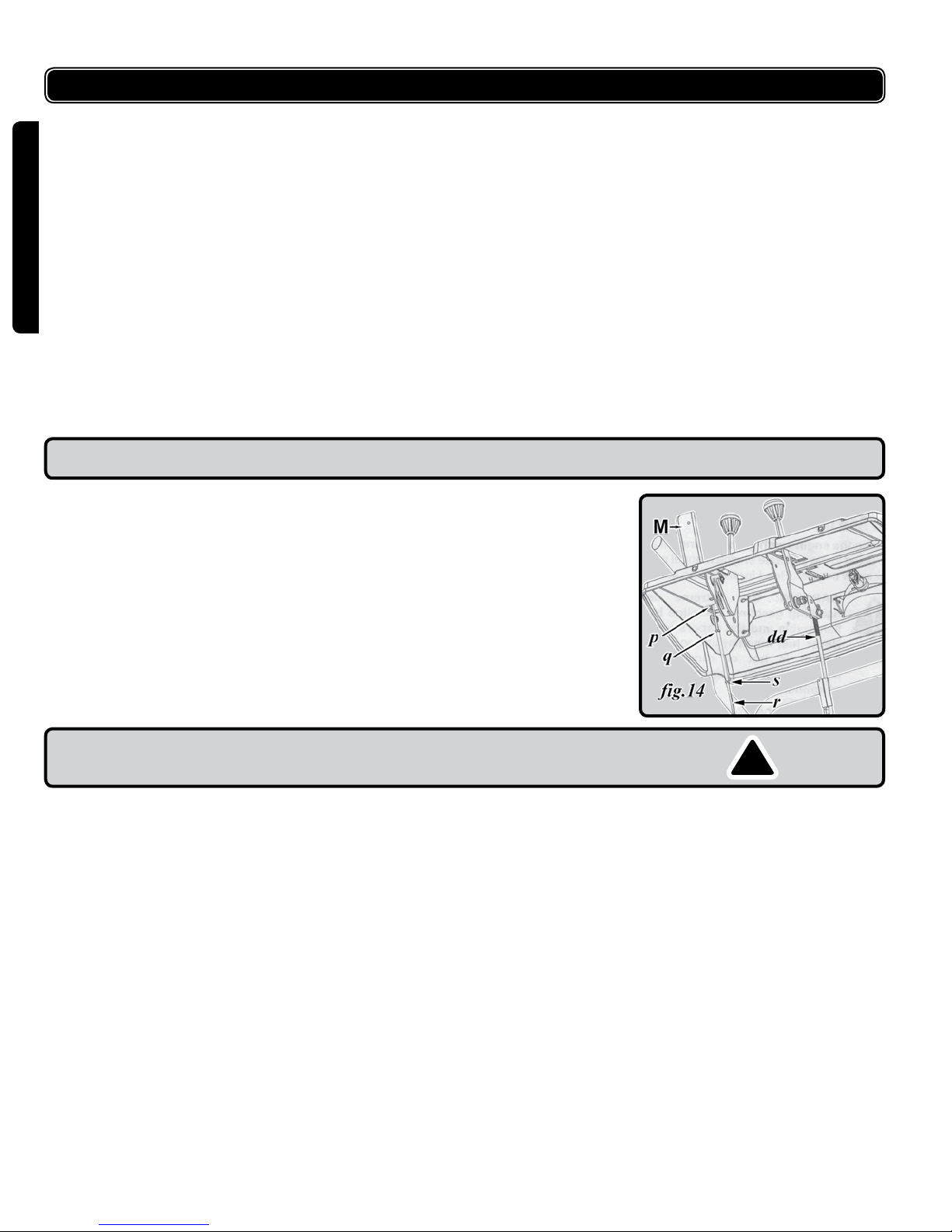
1. When the auger control (M, g.10 & 14) is released and in the disengaged
“up” position, the auger control cable (r, g.14) should have very slight slack. It
should NOT be tight.
2. In a well-ventilated area, start the snowthrower engine as instructed earlier in
this section.
3. While standing in the operator’s position (behind the snowthrower), engage the
auger.
4. Allow the auger to remain engaged for approximately ten (10) seconds before
releasing the auger control. Repeat this several times.
5. With the engine running and the auger control in the disengaged ”up” position,
walk to front of the machine.
6. Conrm that the auger has completely stopped rotating and shows NO sign of
motion.
IMPORTANT: If the auger shows ANY signs of rotating, immediately return
to the operator’s position and shut off the engine. Wait for ALL moving
parts to stop before re-adjusting the auger control.
7. To readjust the control cable (r, g.14), loosen the two hex jam nuts (q, g.14)
on the auger control cable ”Z” tting (p, g.14) with a wrench.
8. Rotate the coupling end of the cable (s, g.14) clockwise to provide more slack.
9. Retighten the hex jam nuts (q, g.14) with a wrench.
10. Repeat Auger Control Test to verify proper adjustment has been achieved.
11. Repeat the previous steps to provide more slack in cable if necessary.
!
12 WSG112
OPERATING PROCEDURES
CLEAN-OUT TOOL
The clean-out tool is conveniently fastened to the rear of the auger housing
with a mounting clip (T, g.10). Should snow and ice lodge itself in the chute
assembly during operation, proceed as follows to safely clean the chute and
chute opening:
1. Release both the Auger Control and the Drive Control/ Auger control lock.
2. Stop the engine by moving the throttle to the stop position.
3. Remove the clean-out tool from the mounting clip.
4. Use one end of the clean-out tool to dislodge and scoop any snow and ice
which has formed in and near the chute assembly.
!
WARNING: Never use your hands to clean snow and ice from the chute or
auger housing. Use the clean-out tool or a stick to unclog.
5. Refasten the clean-out tool to the mounting clip on the rear of the auger
housing and restart the engine.
6. While standing in the operator’s position (behind the snowthrower), engage the
auger control for a few seconds to clear any remaining snow and ice from the
chute assembly.
OPERATING TIPS
NOTE: Allow the engine to warm up for a few minutes.. The engine will not
develop full power until it reaches operating temperature.
ENGLISH
WARNING: The temperature of the mufer and the surrounding areas may
!
exceed 65
For the most efcient snow removal, remove snow immediately after it falls.
Discharge the snow downwind whenever possible.
Slightly overlap each previous path.
Set the skid shoes 6 mm (1/4”) below the shave plate for normal use.
•
The skid shoes may be adjusted upward (to lower the shave plate) for
hard-packed snow.
• Adjust downward (to raise the shave plate) when using on gravel or
crushed rock.
Be certain to follow the precautions found in the To Stop Engine section to
prevent possible freeze-up.
Clean the snowthrower thoroughly after each use.
o
C (150
o
F). Avoid these areas.
v.090220 13
ADJUSTMENT
WARNING: NEVER attempt to make any adjustments while the engine is
running, except where specied in the operator’s manual.
AUGER CONTROL
Refer to Auger Control Test in the Operating Procedures section to adjust
the auger control.
DRIVE CONTROL AND SHIFT LEVER
ENGLISH
To check the adjustment of the drive control and shift lever, proceed as follows:
1. With the engine off, move the shift lever all the way forward to the highest
speed.
2.
With the drive control released, push the snowthrower forward. The unit should
roll forward. Then engage the drive control. The wheels should stop turning.
3. Now release the drive control and push the unit again.
4. Move the shift lever back to the fast reverse position then all the way forward
again. There should be no resistance in the shift lever, and the wheels should
keep turning.
5. If you feel resistance when moving the shift lever or the wheels stop when they
should not, loosen the jam nut on the drive control cable and unthread (loosen)
the cable one turn.
6. If the wheels do not stop when you engage the drive control, loosen the jam nut
on the drive control and thread in (tighten) the cable one turn.
7. Re-check the adjustment and repeat as necessary.
8. Tighten the jam nut to secure the cable when correct adjustment is reached.
If you are uncertain that you have reached the correct adjustment, proceed as
follows:
WARNING: Drain the gasoline out of the snowthrower’s tank, or place a
piece of plastic lm under the gas cap to avoid spillage BEFORE making the
adjustment.
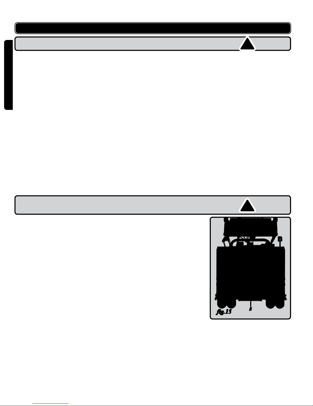
1. Tip the snowthrower forward, allowing it to rest on the front of the auger
housing (B, g.15).
2.
Remove the frame cover (s, g.15) underneath the snowthrower by removing
the six self-tapping screws.
!
!
14 WSG112
ADJUSTMENT
3. With the drive control released, there must be clearance between the friction
wheel (t, g.16) and the drive plate (x, g.16) in all positions of the shift lever.
4. With the drive control engaged, the friction wheel must contact the drive plate.
If adjustment is necessary:
1. Loosen the jam nut on the drive cable (v, g.16).
2. Adjust the cable as necessary. Refer to Figure 14.
3. Retighten the jam nut to secure the cable when correct adjustment is reached.
4. Re-assemble the frame cover (s, g.15).
NOTE: If you placed plastic lm under the gas cap, be certain to remove it
before operating the snowthrower.
SHIFT ROD ADJUSTMENT
To adjust the shift rod, proceed as follows:
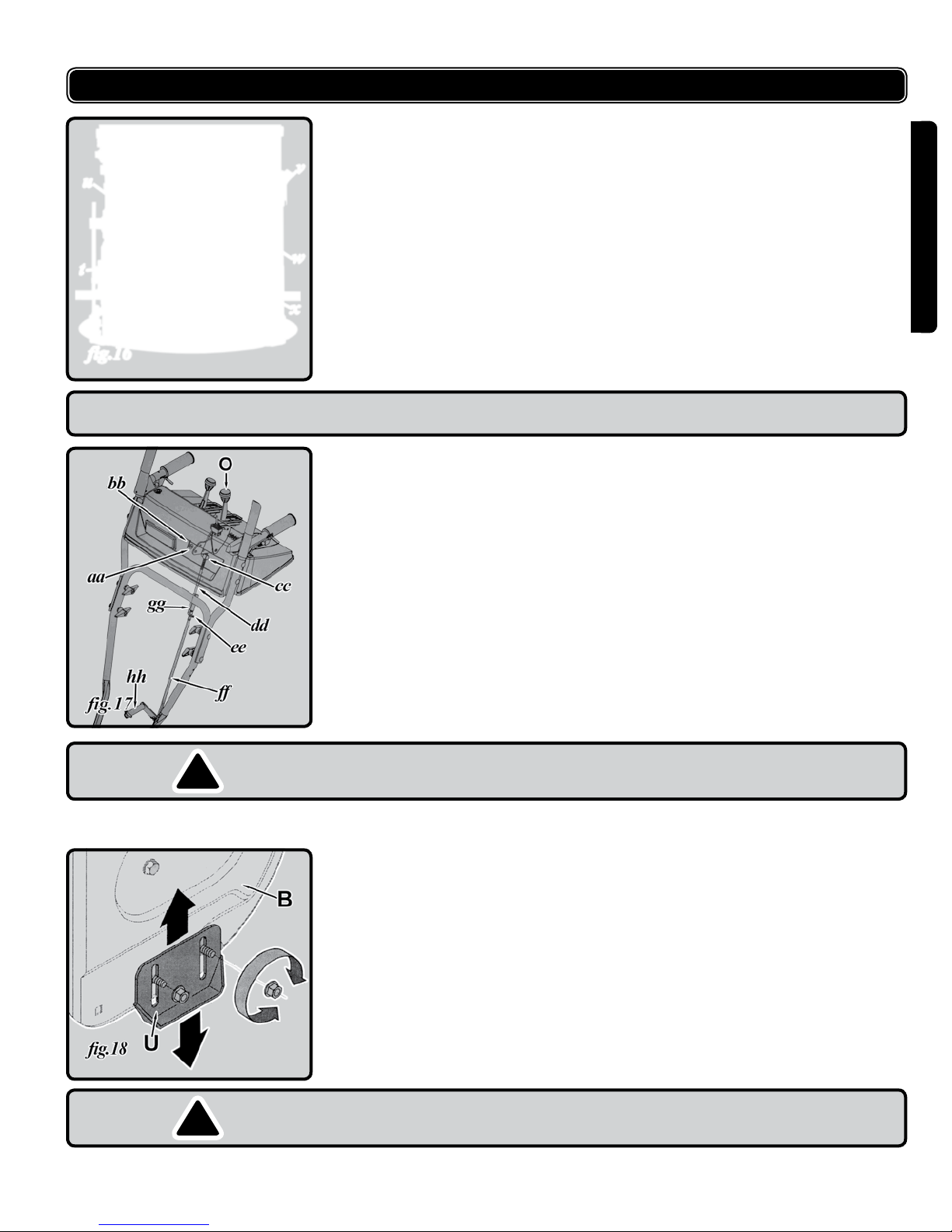
1. Remove the haipin clip (ee, g.17) and slide the shift rod connector (gg, g.17)
up, to separate the upper shift rod (dd, g.17) from the lower shift rod (ff,
g.17).
2.
Place the shift lever (O, g.17) into the sixth (6) position.
3. Rotate the shift arm clockwise (from the operator’s position) as far as it will go.
4. Thread the upper shift rod downward until the elbow on its lower end aligns
with the hole found in the lower shift rod.
5. Reconnect the upper shift rod to the lower shift rod by reinserting the hairpin
clip removed earlier and sliding the shift rod connector back down into place.
ENGLISH
IMPORTANT: Make certain to check for correct adjustment of the shift rod
!
as instructed under items 1 - 6, Drive Control and Shift Lever, above in the
Adjustment section, before operating the snowthrower.
SKID SHOES
The space between the shave plate and the ground can be adjusted.
For close snow removal on a smooth surface, raise skid shoes (U, g.18) higher
on the auger housing (B, g.18).
Use a middle or lower position when the area to be cleared is uneven.
WARNING: Do not operate this snowthrower on gravel as loose gravel can
!
be easily picked up thrown by the auger causing injury to be operator and/or
damage to the snowthrower.
v.090220 15

ADJUSTMENT
Adjust skid shoes by loosening the four ange lock nuts and carriage bolts.
Move skid shoes to desired position.
Make certain the entire bottom surface of skid shoe is against the ground to
avoid uneven wear on the skid shoes.
Retighten nuts and bolts securely.
CARBURETOR
Minor carburetor adjustment may be required to compensate for differences in
fuel, temperature, altitude and load.
ENGLISH
Refer to the separate engine manual packed with your unit, for carburetor
adjustment information.
MAINTENANCE
WARNING:
Before lubricating, repairing, or inspecting, disengage all controls and stop
engine.
Wait until all moving parts have come to a complete stop.
Disconnect spark plug wire and ground it against the engine to prevent
unintended starting.
Always wear safety glasses during operation or while performing any
adjustments or repairs.
!
LUBRICATION
Engine
Refer to the separate engine manual packed with your unit for all engine lubrication
instructions.
WARNING: If any adjustments need to be made to the engine while the engine
is running (e.g. carburetor), keep clear of all moving parts. Be careful of mufer,
engine and other surrounding heated surfaces.
Gear Shaft
Lubricate the gear shaft with 6-in-1 grease (available at automotive stores) at
least once a season or after every 25 hours of operation
IMPORTANT: Keep all grease and oil off of the rubber friction wheel and
aluminum drive plate.
Chute Directional Control
The worm gear on the chute directional control should be greased with multipurpose
automotive grease.
Gear Case
The gear case is lubricated with grease at the factory and it does not require
checking. If dis-assembled for any reason, lubricated with 60 mL (2 ounces) of
Shell Alvania grease EPB00 or equivalent. Before re-assembling, remove old
sealant and apply new sealant.
IMPORTANT: Do not overll the gear case, since damage to the seals could
result. Be sure the vent plug is free of grease in order to relieve pressure.
!
!
!
16 WSG112
MAINTENANCE
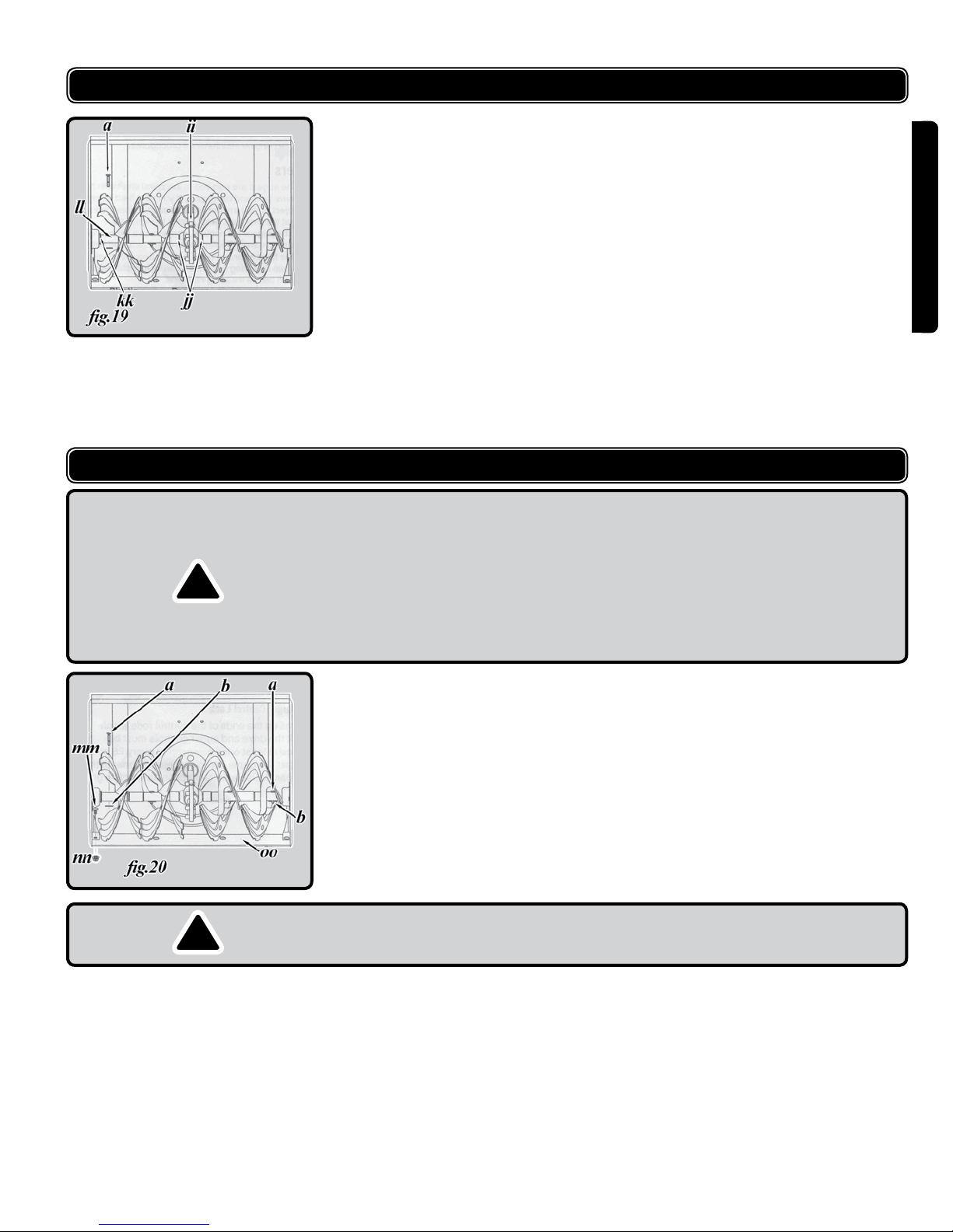
Auger Shaft
At least once a season, remove the shear pins (a, g.19) on the auger shaft (ll,
g.19). Spray lubricant inside the shaft and lubricate the plastic auger bearings
(kk, g.19) on the side of the frame with light oil at least once a season.
Auger Bearings
Every season lubricate the auger bearings (jj, g.19) with light oil.
Drive and Shifting Mechanism
Lubricate at least once a season or after 25 hours of operation.
1. Remove the rear cover
2. Refer to Figure 16. Lubricate any chains, sprockets, gears, bearings, shafts,
and shifting mechanism at least once a season.
3. Use engine oil or a spray lubricant.
4. Avoid getting oil on the friction wheel rubber and aluminum drive plate.
Drive/Auger Control Lock
The cams on the ends of the control rods which interlock the drive and auger
controls accessed beneath the handle panel. Use a multi-purpose automotive
grease to lubricate them.
ENGLISH
SERVICING
WARNING:
Before servicing, repairing, or inspecting, disengage all clutch levers and stop
engine.
Wait until all moving parts have come to a complete stop.
!
Disconnect spark plug wire and ground it against the engine to prevent
unintended starting.
Always wear safety glasses during operation or while performing any
adjustments or repairs.
ENGINE
Refer to the separate engine manual packed with your unit for all engine
maintenance procedures.
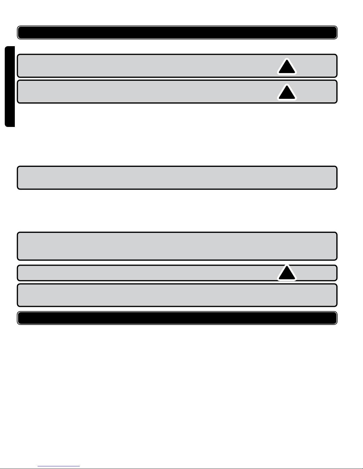
AUGERS
The augers are secured to the spiral shaft with two shear pins (a, g.20) and
cotter pins (b,g.20). If you hit a hard foreign object or ice jam, the snowthrower
is designed so that the pins may shear.
If the augers will not turn, check to see if the pins have sheared. Replacement
shear pins and cotter pins have been provided with the snowthrower. When
replacing bolts, spray an oil lubricant into shaft before inserting new pins.
IMPORTANT: NEVER replace the auger shear pins with standard pins. Any
!
damage to the auger gearbox or other components as a result of doing so will
not be covered by your snowthrower’s warranty.
SHAVE PLATE AND SKID SHOES
The shave plate and skid shoes on the bottom of the snowthrower are subject to
wear. They should be checked periodically and replaced when necessary.
To remove skid shoes, remove four carriage bolts and ange lock nuts.
(See g.18)
To remove the shave plate (oo, g.20), remove the carriage bolts (mm,
g.20) and ange lock nuts (nn, g.20) which attach the shave plate to the
snowthrower housing.
Reassemble the new shave plate, with heads of carriage bolts to the inside of
the housing. Tighten securely.
v.090220 17
SERVICING
OFF- SEASON STORAGE
WARNING: Never store the machine or fuel container indoors where there is an
open ame, spark, or pilot light such as on water heater, furnace, clothes dryer,
or other gas appliance.
WARNING: Drain fuel into an approved container outdoors, away from an open
ame. Allow engine to cool. Extinguish cigarettes, cigars, pipes, and other
sources of ignition prior to draining fuel.
Fuel left in engine for extended periods deteriorates and will cause starting
ENGLISH
problems.
If unit is to be stored over 30 days, prepare for storage as follows:
1. Remove gasoline from carburetor and fuel tank to prevent gum deposits from
forming on these parts and causing possible malfunction of engine.
2. Run engine until fuel tank is empty and engine stops due to lack of fuel.
3. Drain carburetor by pressing upward on bowl drain, located below the
carburetor cover.
NOTE: Fuel stabilizer is an acceptable alternative for minimizing the
formation of fuel gum deposits during storage. Do not drain carburetor if
using a fuel stabilizer.
Wipe equipment with an oiled rag to prevent rust.
4.
5. Remove spark plug and pour one ounce of engine oil through spark plug
hole into the cylinder. Cover spark plug hole with rag. Crank engine several
times to distribute oil. Replace spark plug.
Follow the lubrication recommendations found in the Maintenance section.
6.
Always store the snowthrower in a clean, dry area.
7.
NOTE: When storing any type of power equipment in an unventilated or metal
storage shed, care should be taken to rust-proof the equipment. Using a light
oil or silicone, coat the equipment, especially any chains, springs, bearings and
cables.
!
!
WARNING: Repairs should be made by an authorized repair centre. Opening
this tool could invalidate your warranty.
NOTE: With regard to the warranty, the following are deemed consumable parts:
cotter pins, shear pins, shave plate, auger belt, skid shoes, etc., and thus not
covered.
WARRANTY
All products distributed by Airco Hong Kong Ltd. are warranted against
manufacturers’ faults and defects for a period of one year from the date of
purchase by the end user. The Company will REPAIR OR REPLACE, AT ITS OWN
OPTION, merchandise deemed by the company to be defective, provided that
is has not been misused, abused, altered, or repaired by anyone other than an
authorized repair centre. Retain proof of purchase. Return the defective product to
the place of purchase.
This warranty does not extend to parts deemed consumables, such as brad and
staple gun driver blades, grinding discs, electric motor brushes, welding contact
tips, etc. All warranty claims must have prior authorization and must be shipped
prepaid to an authorized repair depot, accompanied by a copy of the invoice
specifying the date that the item was sold to the end user. You should take any tool
with a problem back to where you purchased it, accompanied by your receipt.
Airco Hong Kong Ltd.
Tel: 877.840.0840
18 WSG112
!

TROUBLESHOOTING
PROBLEM CAUSE REMEDY
Engine fails to start Fuel tank empty, or stale fuel. Fill tank with clean, fresh gasoline. Fuel
becomes stale after thirty days.
Blocked fuel line Clean the fuel line.
Choke/Run button not in the CHOKE
position.
Faulty spark plug Clean, adjust gap or replace.
Spark plug wire disconnected. Connect spark plug wire
Primer button not being used properly. refer to the engine manual
Engine runs erratically Unit running on CHOKE Move the CHOKE/RUN button to RUN.
Blocked fuel line or stale fuel Clean the fuel line; ll the tank with clean
Water or dirt in the fuel system Drain the fuel tank and carburetor. Rell
Loss of power Spark plug wire loose Connect and tighten spark plug wire.
Gas cap vent hole plugged Remove ice and snow from gas cap. Be
Excessive vibration Loose parts or damaged auger. Stop the engine immediately and
Unit fails to propel itself Drive control cable in need of
adjustment.
Drive belt loose or damaged. Replace drive belt. Refer to a service
Unit fails to discharge snow Chute assembly clogged Stop engine and disconnect spark plug
Shear pins sheared Replace shear pins.
Foreign object lodged in auger. Stop engine immediately and disconnect
Auger control cable in need of
adjustment.
Auger belt loose or damaged. Refer to a service centre or call
Move button to CHOKE position.
fresh gasoline.
with fresh fuel.
certain vent hole is clear.
disconnect the spark plug wire. Tighten
all bolts and nuts. If vibration continues,
have the unit serviced by an authorized
service dealer.
Adjust drive control cable. Refer to
Making Adjustment Section.
centre or call
wire. Clean chute and inside of auger
housing with clean-out tool or a stick.
spark plug wire. Remove object from
auger.
Adjust auger control cable. Refer to the
Making Adjustment Section.
840-0840.
1 (877) 840-0840.
1 (877)
ENGLISH
v.090220 19

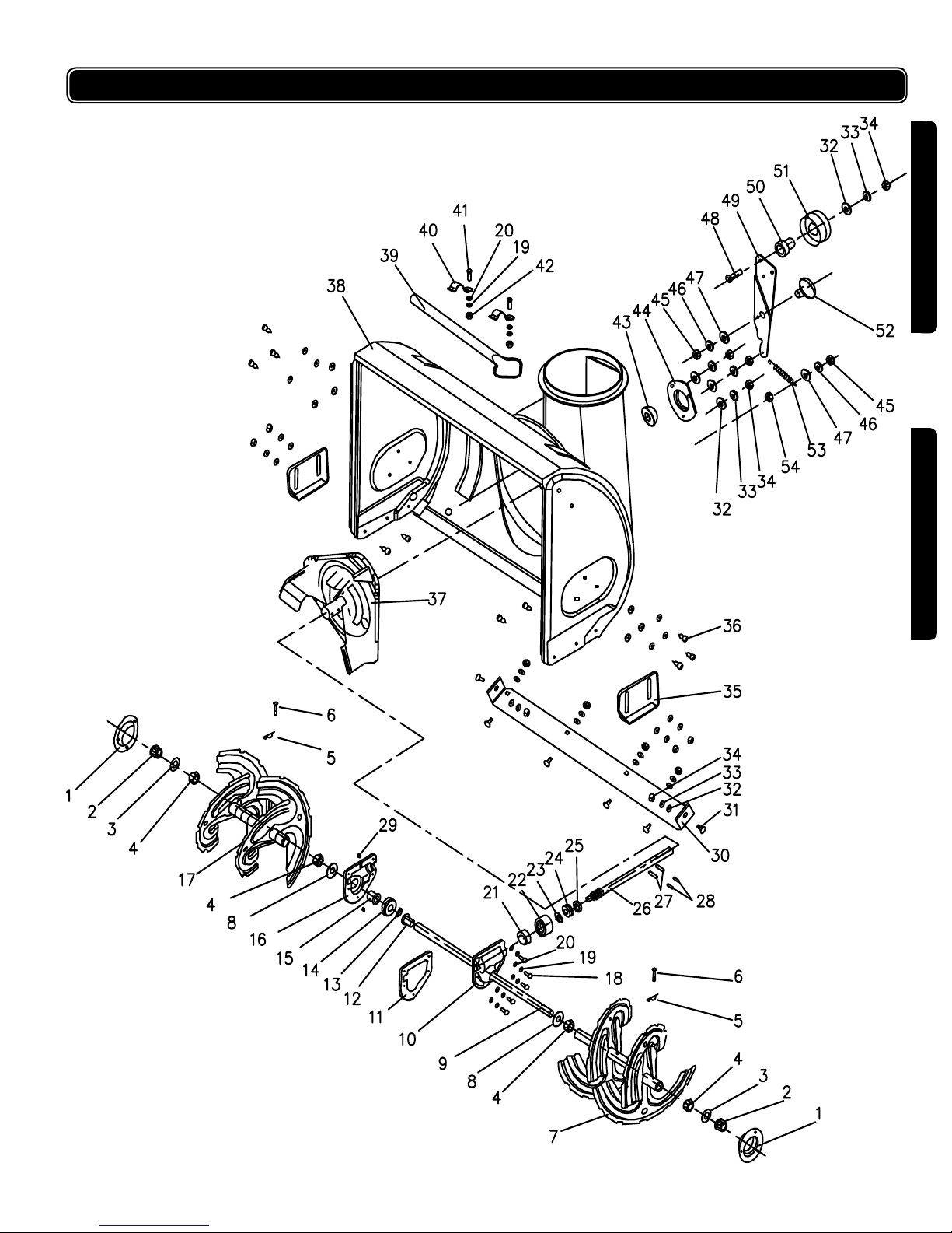
PARTS LIST
Please refer to the schematic drawing on pages 23-25.
PART NO.DESCRIPTION
1 Bearing housing
2 Hex ange bearing
3 Flat washer
4 Flange bushing
5 Bow tie cotter pin
ENGLISH
6 Shear pin
7 Spiral assy. RH
8 Seal
9 Auger axle
10 LH housing
11 Seal
12 Bushing
13 Key 5 x 7.5 x 19
14 Worm gear
15 Bushing
16 RH housing
17 Spiral assy. LH
18 Bolt M6 x 20
19 Spring washer M6
20 Flat washer M6
21 Ball bearing 6001
22 Ball bearing 61904
23 Flat washer
24 Ball bearing 51104
25 Seal
26 Worm shaft
27 Pin 6 x 35
28 Pin 4 x 35
29 Oil cup
30 Shave plate
31 Bolt M8 x 16
32 M8 at washer
33 M8 spring washer
34 M8 lock nut
PART NO.DESCRIPTION
35 Skid shoe
36 Bolt M8 x 16
37 Impeller assy.
38 Auger housing assy.
39 Clean-out tool
40 Clean-out tool mount
41 Bolt M6 x 16
42 Lock nut M6
43 Ball bearing
44 Housing
45 Lock nut M10
46 Spring washer M10
47 Flat washer M10
48 Idler arm bolt
49 Auger idler arm
50 Auger idler arm shaft
51 Flat idler
52 Auger idler arm screw
53 Auger idler arm spring
54 Nut M10
55 Exhaust screen
56 Bolt M10 x 40
57 Engine
58 Belt Cover
59 Screw M6 x 12
60 Screw M6 x 16
61 Screw ST5
62 M5 at washer
63 Belt cover support
64 Extension spring
65 Spacer
66 Pulley half
67 Key 5 x 7.5 x 19
68 Belt*
PART NO.DESCRIPTION
69 Pulley half support
70 Pulley half
71 V-belt**
72 Flat washer
73 Bolt M8 x 35
74 Auger pulley support
75 Auger pulley
76 Key 6 x 18
77 Screw M6 x 10
78 Friction disc seal ring
79 Friction disc shaft
80 Ball bearing 6203
81 Friction disc
82 Flat idler
83 Screw
84 Spacer
85 Drive clutch idler bracket
86 Bolt M8 x 35
87 Bolt M10 x 16
88 Ball bearing
89 Frame assy.
90 Screw
91 Cable roller
92 Drive cable guide bracket
93 Drive cable
94 Shift frame bracket
95 Shift rod assy.
96 Auger cable guide bracket
97 Auger cable guide bracket
98 Auger cable
99 Bolt M6 x 28
100 Frame assy. support
101 Pin retainer
102 Pin
*
Gates 5M800 Polyex belt or equivalent
** Gates 13X895 Tru-Power V belt or equivalent (2 required)
20 WSG112

PARTS LIST
Please refer to the schematic drawing on pages 23-25.
PART NO.DESCRIPTION
103 Wheel
104 Spacer
105 Hex bushing
106 Flat washer M20
107 Large gear
108 Spring pin 4 x 35
109 Shaft
110 Hex drive shaft
111 Friction plate
112 Friction wheel hub
113 Friction wheel rubber
114 Friction wheel assy.
115 Seal ring 35
116 Flat washer
117 Spacer
118 Extension spring
119 Friction wheel support
bracket
120 Frame cover
121 Hex bolt M6 x 12
122 Frame cover
123 M5 at washer
124 Screw M5 x 10
125 Engagement handle assy.
LH
126 Spring
127 Screw M4 x 16
128 Handle engagement shaft
129 Drive / auger control lock
130 Spring
131 Drive / auger control lock
132 Engagement handle assy
RH
133 Hand control panel
134 ON/OFF switch cover
PART NO.DESCRIPTION
135 Lamp
136 ON/OFF switch
137 Lamp bracket
138 Cable
139 Chute deector cable
holder
140 Chute deector cable
bracket
141 Screw M8 x 35
142 Upper chute
143 Bolt M8 x 20
144 Lock Nut M5
145 Bolt M5 x 35
146 Lower chute
147 Safety guard
148 Bolt M6 x 25
149 Flange retainer
150 Bolt M8 x 20
151 Lower handle
152 Screw
153 Washer
154 Handle knob
155 Chute deector cable
bracket
156 Bolt M5 x 40
157 Upper handle RH
158 Cable clip
159 Upper handle LH
160 Handle grip
161 Torsion spring
162 Chute tilt control lever
163 Bolt M10 x 40
164 Shift lever
165 Chute cable 1
166 Chute cable 2
PART NO.DESCRIPTION
167 Chute deector cable
holder
168 Control knob
169 Screw ST4.2 x 14
170 Hand control panel frame
171 Screw ST4.2 x 14
172 Flat washer M4
173 Screw ST4.2 x 16
174 Pin
175 Pin
176 Hex nut M8
177 Upper shift rod
178 Shift rod connector
179 Lower shift rod
180 Shift arm assy.
181 Seal ring
182 Chute directional control
hand crank
183 Chute directional rod (Z
-shape)
184 Chute rod bracket
185 Rubber washer
186 Screw M5 x 25
187 Pin 1.6 x 18
188 Pin
189 Pin
190 Gimbal
191 Gimbal connector
192 Gimbal
193 Chute directional control
rod (at)
194 Spacer
195 Chute directional control
rod (at) holder
196 Worm shaft
197 Worm gear
198 Bushing
199 Worm gear bracket
ENGLISH
FRANÇAIS
v.090220 21

ENGLISH
v.090220 23
FRANÇAIS
22 WSG112
SCHEMATIC DRAWING / SCHÉMA
ENGLISH
FRANÇAIS
v.090220 23
 Loading...