

Page 1
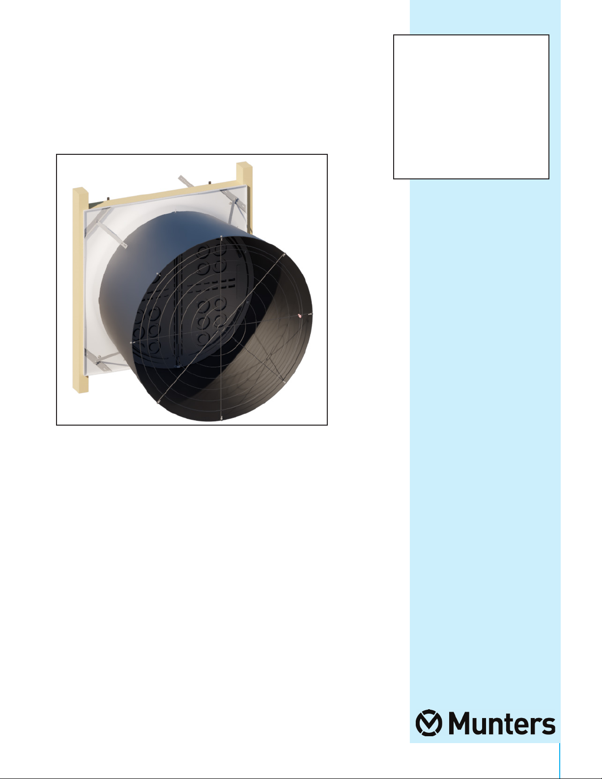
WM54K
Wall Mount Fan
Instruction Manual
with Damper Door
6-pack
WM Fiberglass Wall Mount Fan
with Damper Door - 6 pack
Models: WM54xKxCB-6PK
QM1078r1
1© Munters Corporation, September 2019
Page 2

WM54K Fiberglass Wall Mount Fan with Damper
Instructions for Use and Maintenance
Thank You:
Thank you for purchasing a Munters Wall Mount Fan with Damper. Munters equipment is designed to be the
highest performing, highest quality equipment you can buy. With the proper installation and maintenance it will
provide many years of service.
Please Note:
To achieve maximum performance and insure long life from your Munters product it is essential that it be installed
and maintained properly. Please read all instructions carefully before beginning installation.
Warranty:
For Warranty claims information see the “Warranty Claims and Return Policy” form QM1021 available from the
Munters Corporation office at 1-800-227-2376 or by e-mail at aghort.info@munters.com.
Conditions and Limitations:
• Products and Systems involved in a warranty claim under the “Warranty Claims and Return Policy” shall have
been properly installed, maintained and operated under competent supervision, according to the instructions
provided by Munters Corporation.
• Malfunction or failure resulting from misuse, abuse, negligence, alteration, accident or lack of proper
installation or maintenance shall not be considered a defect under the Warranty
.
2
QM1078r1
© Munters Corporation, September 2019
Page 3

Index
Chapters Page
1. Unpacking the Equipment 4
2. Installation Instructions 7
2.2 Fan Assembly 8
2.4 Cone Installation 17
2.5 Motor Mounting 21
3. Electrical Wiring 26
4. Operation 28
1.1 Parts List 4
1.2 Fan Dimensions 6
1.3 Tools for Installation 6
2.1 Wall Framing 7
2.3 Damper Door Installation 11
3.1 Recommended Wiring 27
5. Maintenance 29
6. Winterizing 31
7. Troubleshooting 32
8. Exploded View and Parts List 33-35
6.1 Winterizing 31
6.2 Winter Weather Protection 31
QM1078r1
3© Munters Corporation, September 2019
Page 4
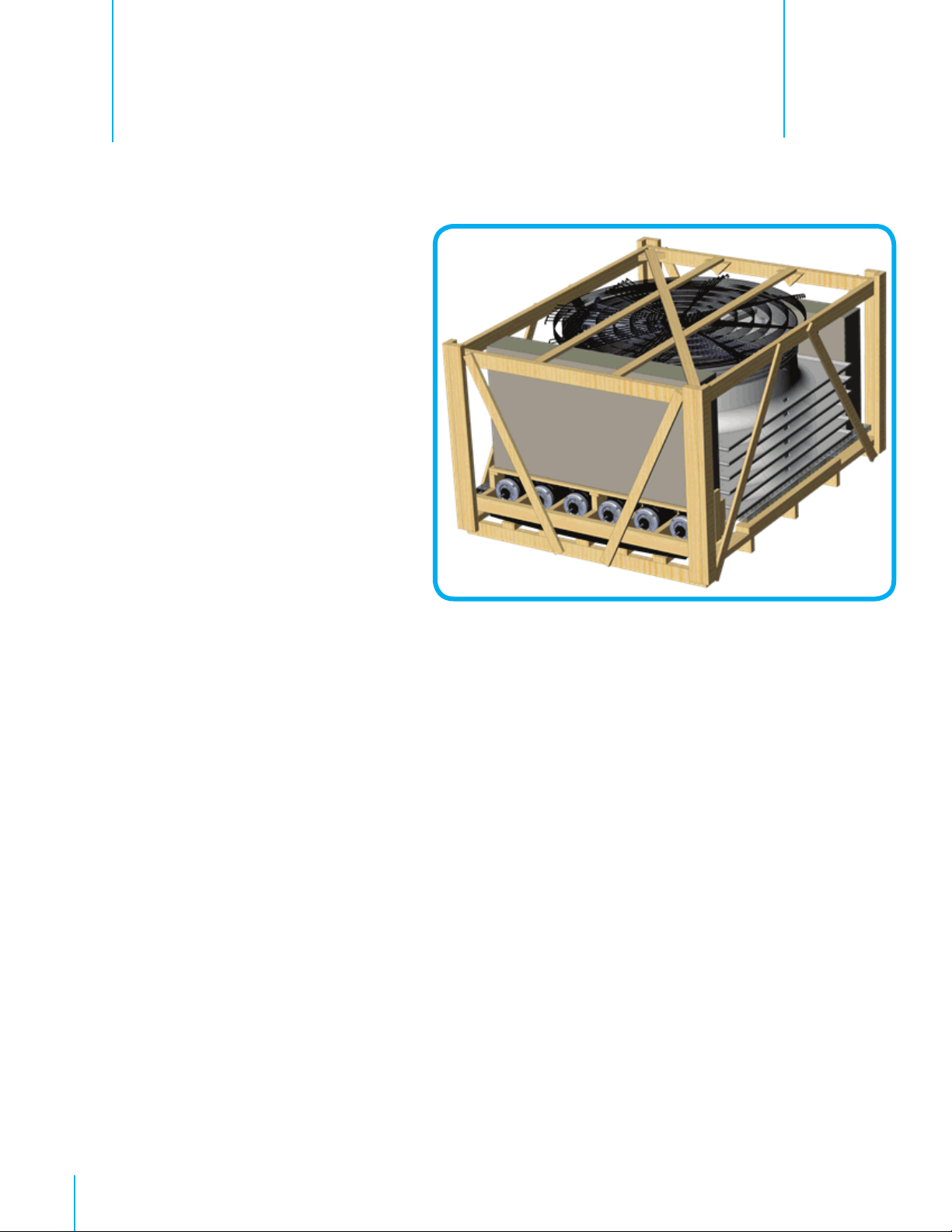
Unpacking the Equipment
1.1 Parts List
Each Crate Includes Parts to build 6 fans:
Each WM54K Fan Requires:
1 – Orifice Panel, Fiberglass
1 – Propeller
1 – Tube Strut, Powder Coated
1 – Motor
1 – Drip Shield, AL
1 – Main Frame Assembly, AL
1 – Door Assembly, PL
4 – Cone Sections, PL
1 – Cone Guard
1 – Inlet Guard
½ – Bulk Parts Package (BK1154) For 2 Fans
1.
BK1154 – ½ of Bulk Parts Package needed for 1 – WM54K
1 – Motor Base Bracket, Powder Coated
1 – Belt Tensioner Bracket, Powder Coated
4 – Cone Support Brackets, PC Type, Galvanized
4 – Cone/Strut Mounting Brackets, Galvanized
1 – V-Belt, A-Section
1 – Hub with Bearings and Shaft
1 – Motor Sheave, CI
1 – Prop Sheave, AL
1 – 3” Idler Pulley, A-Section C.I., Blue
1 – Rotary Tensioner Arm, AL
1 - Motor Mount Stiffener Bracket, Galvanized
2 – Tension Springs, 11.0”L./10.8”L., SS
1 – Hardware Package (HP1389)
1 – Coated Cable with ferrule, 100”L.
2 – Wing for Damper Door, HDPE, BLK
4
QM1078r1
© Munters Corporation, September 2019
Page 5
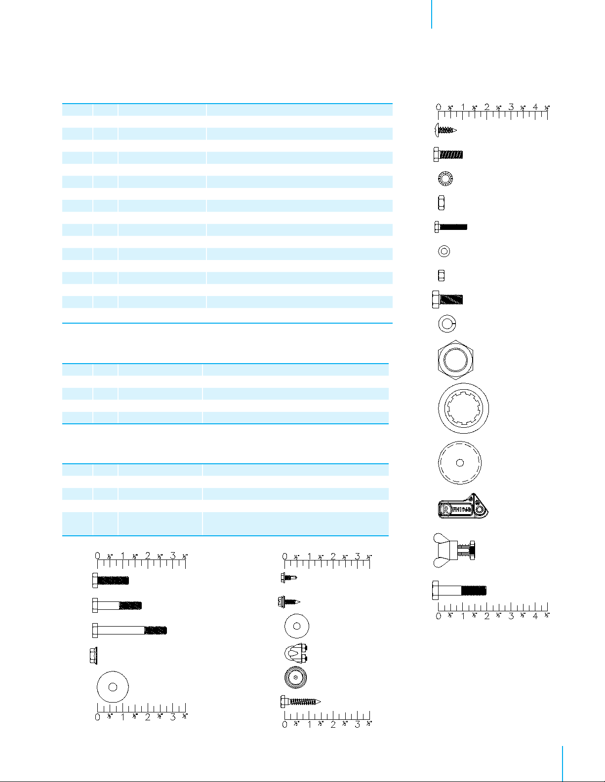
HP1389 – Hardware Package for 1 – WM54K
ID Qty. Cat. No. Description
[B] 1 KS1901 6.3mm x 19mm Tapping Screw, ZP
[C] 4 KS1928 M8-1.25 x 25mm Hex Bolt, ZP (HP1382 only)
[D] 4 KW4906 M8 Star Lock Washer, BLK
[E] 4 KN1849 M8-1.25 x 8mm Hex Nut, ZP
[F] 4 KS1926 M6-1.0 x 30mm Hex Bolt, ZP
[G] 4 KW4901 M6 x 12mm Flat Washer, ZP
[H] 4 KN1855 M6-1.0 x 6mm Hex Nut, ZP
[J] 1 KS1931 M10-1.5 x 25mm Hex Bolt, ZP
[K] 1 KW3509 10mm Splitlock Washer, ZP
[L] 1 KN1860 M25-2.0 x 10mm Hex Nut, ZP
[M] 1 KX1130 Shaft Shield for Prop Sheave, AL
[N] 1 KX1208 40mm Cover Cap, Black PL
[R] 8 FH1968 1-Hole Pivoting Shutter Clip, PL
[T] 1 AC0211 & AC0212 Azuma Bolt & Nut, Blue PL
[X] 1 KS1046 M10-1.5 x 50mm Hex bolt, ZP
1 HK1001 Hardware Kit WM54K Fan Assembly, #1 of 2
1 HK1002 Hardware Kit WM54K Fan Assembly, #2 of 2
1 LB2647 Specification Label for WM54K
HK1001 – Hardware Kit for 1 – WM54K Fan
ID Qty. Cat. No. Description
[AA] 18 KS1007
[BB] 4 KS1029
[CC] 7 KS1075
[DD] 37 KN0704
[EE] 10 KW3011
5
⁄16”-18 x 1.25” SRTD Flange Head Bolts, SS
5
⁄16”-18 x 1.75” SRTD Flange Head Bolts, SS
5
⁄16”-18 x 2.75” SRTD Flange Head Bolts, SS
5
⁄16”-18 SRTD Flange Nuts, SS
5
⁄16” x 1¼”O.D. Flat Washer, SS
Unpacking the EquipmentChapter 1
[B]
[C]
[D]
[E]
[F]
[G]
[H]
[J]
[K]
[L]
[M]
HK1002 – Hardware Kit for 1 – WM54K Fan
ID Qty. Cat. No. Description
[FF] 4 KS2250 #10-16 x ½” TEK Screw, SS
[GG] 7 KS1400 #10-12 x
[HH] 1 KW3012 ¹⁄₄” x 1”O.D. Flat Washer, SS
[JJ] 2 AC1381
[KK]
[LL]
2 KX1158 Hole Plug, 0.73”-0.76” Dia., BLK PL
1 KS2463
1
⁄8” Dia. Cable Clamp, ZP
1
⁄4” x 1.5” HEX Lag Screw,ZP
[AA]
[BB]
[CC]
[DD]
[EE]
3
⁄4”, SLTDHX, Seal-Washer Screw, ZP
[FF]
[GG]
[HH]
[JJ]
[KK]
[LL]
[N]
[R]
[T]
[X]
QM1078r1
5© Munters Corporation, September 2019
Page 6
Unpacking the EquipmentChapter 1
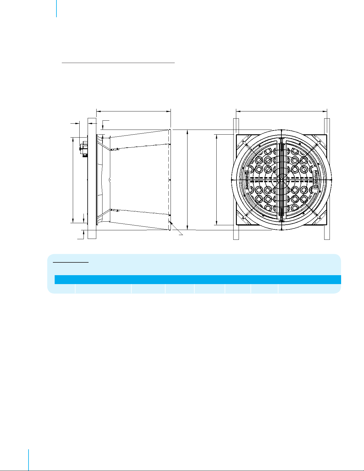
1.2 Fan dimensions
Fan Specifications: 60Hz shown (50Hz available)
Power: 115/230 VAC* or 208-230/460 VAC
Phase: 1 or 3
*Available voltages vary depending on HP
AB
C
Wall Opening (W.O.)
F
E
A
D - Dia.
Guard
Dimensions:
Size A B C* D - Dia. E F Wall Openings
54” 60”W. x 60” H. 49” 6
1
⁄2”66
5
⁄16”3
3
⁄16”4
3
⁄4”56
1
⁄2”W. x 561⁄2”H.
6
1.3 Tools required for installation
10mm [3⁄8”] Socket
13mm [ ½”] Socket
17mm [11⁄16”] Socket or Wrench
27mm [1
36mm Socket or Wrench
3⁄8” Socket
Phillips Screwdriver, #3 Size
5⁄32” Hex Wrench
Wire Cutting Pliers
QM1078r1
*Dimension varies depending on wall construction and motor configuration.
1
⁄16”] Wrench
5
⁄16” Socket or Wrench
1
⁄8” Drill Bit
© Munters Corporation, September 2019
Page 7
Installation Instructions
2.
2.1 Wall framing
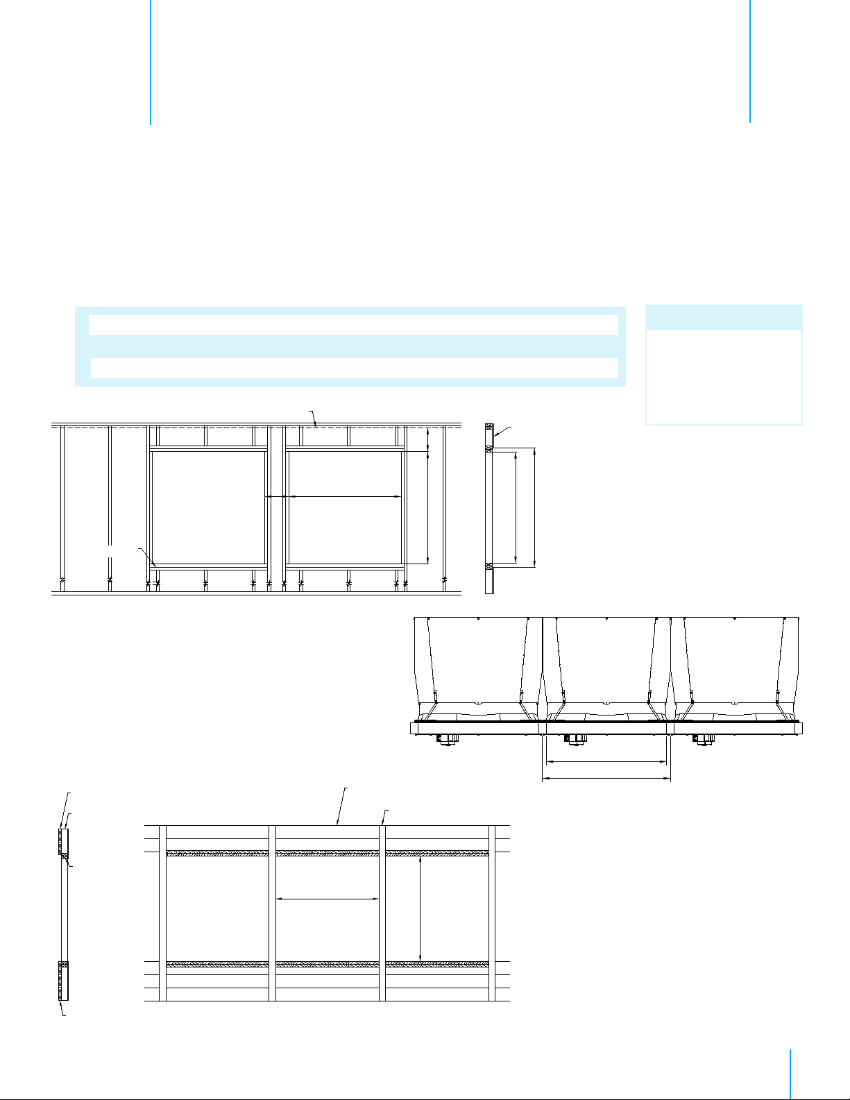
Step 1
Construct framed opening to correct size according to the Wall Opening listed in chart A below.
See Figure 1A and 1B. When installing exterior sheet metal before fan, leave 2” of the framing
exposed on all sides so the orifice can mount flush to the frame.
Chart A
Fan Dia.
54”
Framing
Wall Opening
(W. x H.)
56½” W. x 56½” H.
Ceiling
See minimum
spacing notes in
Chart A
12” recommended; 3½” minimum
Z
(see chart A)
Figure 1A Frame Construction
Minimum Spacing
'Z'
12"
W
H
Center To Center
Dimension
60” Minimum
Note:
Damper doors should
be carefully set aside
out of direct sunlight
until needed.
Stud Wall
(see chart A)
W x H Wall Opening
Sheet Metal Opening
Top View
2 x 8 Header boards
4 x 4 or
4 x 6 Posts
2 x 4
Framing
2 x 8 Banner boards
Figure 1B 4 x 4 Post Construction - Elevation View
W
(see chart A)
Ceiling
4 x 4 or 4 x 6 Posts
H
(see chart A)
561»2”W.
60”W. O.C.
QM1078r1
7© Munters Corporation, September 2019
Page 8
Installation InstructionsChapter 2
2.2 Fan assembly
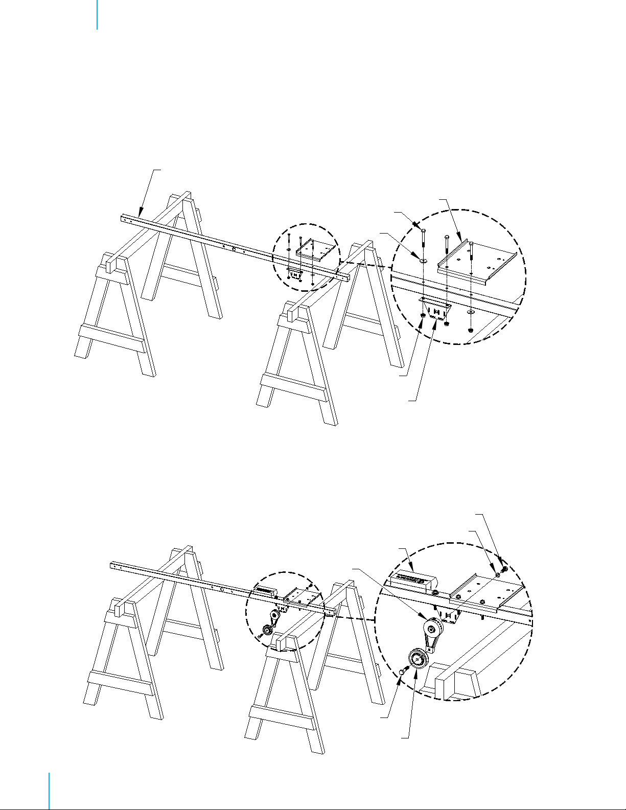
Step 2
Place tube strut on saw horses or a flat work surface. The large center hole should be pointing horizontally.
Attach the Motor Base Bracket and the Belt Tensioner Bracket to the Tube Strut using (3) Long Bolts [CC],
(2) Washers [EE] and (3) Nuts [DD]. The Motor Bracket and the Tensioner Bracket share the middle hole.
See Figure 2A.
Tube Strut
Motor Base Bracket
Long Bolts [CC]
Washer [EE]
Nuts [DD]
Tensioner Bracket
Figure 2A
Step 2B
Attach the 3” Idler Pulley to the Tensioner Arm using Bolt [X]. Then attach the Tensioner Arm assembly to the
Tensioner Bracket using Bolt [J] and Splitlock Washer [K]. Finger tighten only at this time.
See Figure 2B.
Next attach the Specification Label to the Tube Strut as shown, and then mark the box for the appropriate
model fan.
Bolt [J]
Washer [K]
Label
Tensioner Arm
8
QM1078r1
Bolt [X]
Idler Pulley
Figure 2B
© Munters Corporation, September 2019
Page 9

Step 3
Attach Prop Sheave to Hub using (4) Bolt [F], Washer [G] and Nut [H]. See Figure 3.
Prop Sheave
Hub
Washer [G]
Bolt [F]
Bolt [F]
Installation InstructionsChapter 2
Washer [G]
Nut [H]
Prop Sheave
Figure 3
Hub
Step 4
Rotate Tube Strut on saw horses so Motor Bracket is pointing up. Slide Shaft Shield [M] over hub shaft
as shown in Figure 4. Attach Sheave/Hub Assembly to Tube Strut using (1) Hex Nut [L] and tighten to
52 ft-lbs [70 N-m] torque. See Figure 4. Place Plastic Cover Cap [N] over Hex Nut and fasten in place
with (1) Tapping Screw [B]. See Figure 4. Set aside the Strut Assembly for use in a later step.
Tapping Screw [B]
Cap Cover [N]
Hex Nut [L]
Shaft Shield [M]
Hub Assembly
Figure 4
QM1078r1
9© Munters Corporation, September 2019
Page 10
Installation InstructionsChapter 2
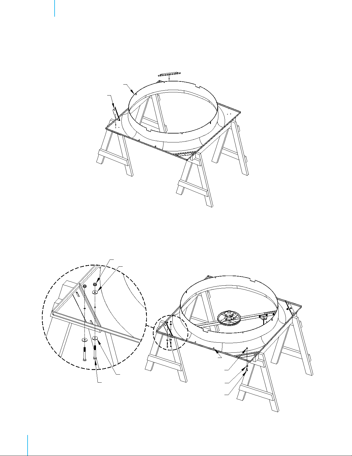
Step 5
Place Orifice Panel on saw horses with the round orifice pointing up and place (1) Cone/Strut Mounting
Bracket in each corner of the Orifice Panel. See Figure 5.
Orifice Panel
Mounting Bracket
Figure 5
Step 6
Corners of Orifice Panel with 2 holes are corners where Strut Assembly attaches. Secure Strut Assembly using
(4) Long Bolts [CC], (6) Washers [EE] and (4) Nuts [DD]. In the opposite corners attach Cone/Strut Mounting
Bracket to the orifice using (1) Short Bolt [AA], Washer [EE] and Nut [DD]. See Figure 6.
Nuts [DD]
Washer [EE]
Drain Hole
Washer [EE]
Long Bolt [CC]
Nuts [DD]
Washer [EE]
10
QM1078r1
Short Bolt [AA]
Figure 6
© Munters Corporation, September 2019
Page 11
Installation InstructionsChapter 2
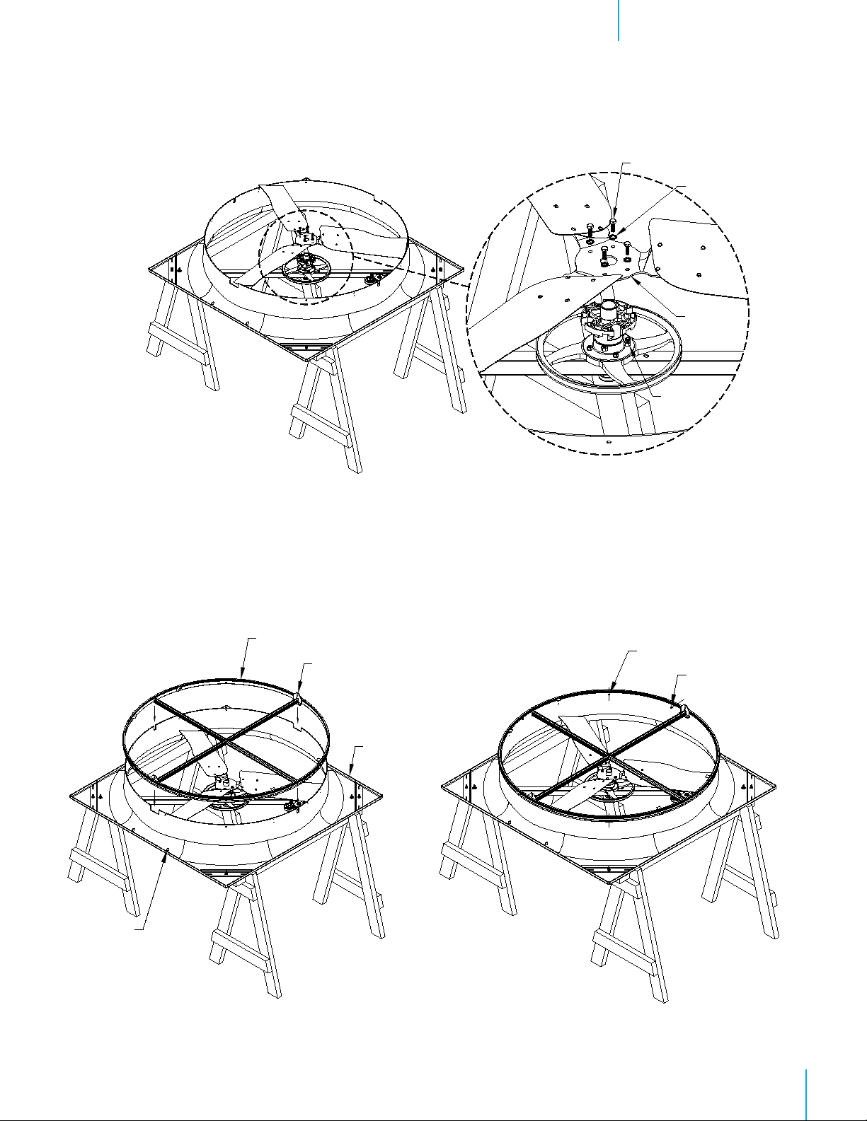
Step 7
Attach Propeller to Hub Assembly using (4) Bolts [C], Washers [D] and Nuts [E]. Tighten bolts to 180 in-lbs.
of torque. See Figure 7.
Bolt [C]
Washer [D]
Propeller
Nut [E]
Figure 7
WM54K Shown
2.3 Damper Door Installation
Step 8
Slide Main Frame Assembly onto Orifice Panel with pin on Main Frame opposite the drain holes.
See Figure 8A. Line up 4 holes in Main Frame with holes in the Orifice and fasten using (4) TEK Screws [FF].
See Figure 8B.
Main Frame
Pin
Orifice Panel
Hole in orifice panel
TEK Screw [FF]
Drain Hole
Figure 8A Figure 8B
QM1078r1
11© Munters Corporation, September 2019
Page 12

Installation InstructionsChapter 2
Step 9
Attach Drip Shield to bottom of framed opening using (3) Barn Screws (Not Provided). See Figure 9A and 9B.
If a 4” wall is used a support board must be installed as shown in Figure 9B. Be sure not to deform Drip Shield
when installing screws.
Barn Screw Barn Screw
Barn Screw
(not provided)
Drip plate
6” Wall
Drip Shield
Drip plate
Support board
4” Wall
Figure 9A Figure 9B
Step 10
Locate Drain Hole in Orifice Panel. This is the bottom of the Panel. Set bottom edge of panel on Drip Shield
ledge and center panel on opening. Secure Panel to wall using (16) Barn Screws (Not Provided).
See Figure10A and 10B.
Orifice Panel
12
QM1078r1
Drain Hole
Drip Shield ledge
Figure 10A Figure 10B
© Munters Corporation, September 2019
Barn Screws (Not Provided)
Page 13

Installation InstructionsChapter 2
Step 11
Carefully remove folded door assembly from box. Open doors and lay them flat on solid surface with the
Munters Logo down. The Bottom of the doors has the Hinge Pin with the Nylon Washers. The Wing sits down
in the Groove of the upper right and lower left doors. For the WM54 the Wing will start just after the last
spring mounting dimple and follow the Groove. Make sure Wing is seated in bottom of Groove and fasten in
place using (3) Seal-Washer Screws [GG] per wing. Make sure Hinge Pins do not fall out. See Figure 11.
Spring Mounting Dimples
Groove in Door
Wing
Seal-Washer
Screw [GG]
Wing
Figure 11
QM1078r1
13© Munters Corporation, September 2019
Page 14

Installation InstructionsChapter 2
Step 12
Carefully turn doors over and pull upper Latch Pin down until the end is flush with top of doors. Make sure
Long Hinge Pin (bottom) does not fall out. See Figure 12.
Latch Pin
14
QM1078r1
Long Hinge Pin
Figure 12
© Munters Corporation, September 2019
Page 15

Installation InstructionsChapter 2
Step 13
Being careful not to let pin fall out, set Doors into Main Frame with Hinge Pin in hole at bottom plate of
Main Frame and push top of Doors into place.
See Figure 13.
Door
Figure 13
Step 14
Separate doors and push them into closed position. Push Latch Pin up into place, then turn short leg of
Latch Pin into recess of door. Secure in place using Seal-Washer Screw [GG] and Flat Washer [HH].
Latch Pin should extend up through upper plate in Main Frame.
See Figure 14.
Latch Pin
Hinge Pin
Figure 14
Latch Pin Leg
Flat Washer [HH]
Seal-Washer Screw [GG]
QM1078r1
15© Munters Corporation, September 2019
Page 16

Installation InstructionsChapter 2
Step 15
Find Coated Cable and insert end opposite ferrule into small hole in upper plate of Main Frame. Pull it
through until ferrule stops at the plate.
See Figure 15.
Ferrule End
Hole in Main Frame
Figure 15
Step 16
On room side of each door drill an 1⁄8” dia. hole in each door through one of the dimples, as shown. For WM54
drill the 4th dimple from the center in both upper quadrants.
See Figure 16.
Drill 4th Dimple
16
QM1078r1
Figure 16
© Munters Corporation, September 2019
Page 17

Installation InstructionsChapter 2
Step 17
From the inside attach each Tension Spring to hole in upper or lower plate of Main Frame using end of spring
with loop. Loop should hook through hole from the door side. Stretch spring and insert opposite end into hole
drilled in door previously.
See Figure 17.
Hole in upper plate
Drilled Hole in
Damper Door
Tension Spring
2.4 Cone Installation
Step 18
Place all 4 cone sections on a flat surface with tabs from one facing slots of the next. See Figure 18A.
Curl up tab end of first cone section and insert tabs up into slots in the next cone section. A mallet may be
needed to seat slots over tabs completely.
connected and laying flat.
Figure 17
See Figure 18B. Repeat this step until all 4 cone sections are
Figure 18A
Figure 18B
QM1078r1
17© Munters Corporation, September 2019
Page 18

Installation InstructionsChapter 2
Step 19A
Fasten each of the joints in the single outer hole using (1) Short Bolt [AA] and Nut [DD], with the nut on
the side with the tabs. At the inner pair of holes of each joint attach (1) Cone Support Bracket to the inner
hole using (1) Bolt [AA] and Nut [DD] with the bolt head on the side with the tabs.
Nut [DD]
See Figure 19A.
Outer hole
Short Bolt [AA]
Short Bolt [AA]
Inner hole
Nut [DD]
Cone Support Bracket
Figure 19A
Step 19B
Stand cone sections on end and curl ends around to form cone with Cone Support Bracket on outside and tabs
on inside. Insert remaining tabs into slots so tabs are inside cone and fasten final joint using (1) Short Bolt [AA]
and Nut [DD], with nut on inside of cone. At the inner pair of holes attach (1) Cone Support Bracket to the
inner hole using (1) Short Bolt [AA] and Nut [DD] with bolt head on inside of cone.
See Figure 19B.
18
QM1078r1
Short Bolt [AA]
Cone Support Bracket
Nut [DD]
Short Bolt [AA]
Nut [DD]
Figure 19B
© Munters Corporation, September 2019
Page 19

Installation InstructionsChapter 2
Step 20A
Install cone onto fan by putting top of cone over top of fan. The hole in tab of one cone section should slide
down over the Frame Pin in the Main Frame assembly. Allow remainder of cone to slide over orifice panel
making sure cone support brackets remain on outside of cone.
Hole in Tab of Cone Section
Frame Pin
See Figure 20A.
Figure 20A
Step 20B
Place end of Cone Support Bracket with slot over bolt holding Cone/Strut Mounting Bracket to the orifice and
secure with Nut [DD].
See Figure 20B. Secure Cone to Fan installing Medium Bolt [BB] through the remaining
hole in the Cone Support Bracket and fasten with Nut [DD]. A long screwdriver may be needed to help align
the holes through Cone Support Bracket, Cone, Main Frame and Orifice. Repeat process for all 4 Cone
Support Brackets.
Use this hole for WM54K
See Figure 20B.
Nut [DD]
Medium Bolt [BB]
Nut [DD]
Figure 20B
QM1078r1
19© Munters Corporation, September 2019
Page 20

Installation InstructionsChapter 2
Step 21
Insert guard into cone with the eyelets facing you. Install eyelets over bolts already installed in cone and fasten
with Nut [DD]. Secure remaining eyelets using Short Bolt [AA] and Nut [DD].
See Figure 21.
Previously installed - Bolt and Nut
Nut [DD]
Short Bolt [AA]
Nut [DD]
Figure 21
Step 22
Loop Coated Cable that was installed in a previous step, around the lower, middle joint in guard and fasten to
itself with Azuma Bolt & Nut [T]. Make sure cable is pulled snug.
See Figure 22.
Note:
When installing cable in
temperatures BELOW 60°F,
leave cable slightly slack
(do not overtighten).
Azuma [T]
20
QM1078r1
Coated Cable
Figure 22
© Munters Corporation, September 2019
Page 21

Installation InstructionsChapter 2
Step 23
If Fans are to be installed 60” O.C., cut the 3 o’clock and 9 o’clock guard wire in the position shown. Push the
side of the cone in as far as possible and fasten the cut guard wire to the attached guard wire using Clamp [JJ].
See Figure 23.
Cut Guard Wire Here
2.5 Motor Mounting
Step 24
Find the Key provided with the Motor and place it in the Keyway on the motor shaft. Place the Motor Sheave
on the Motor shaft with the hub facing towards the motor.
to hold the Sheave in place at this time.
Motor
Figure 23
Motor Sheave
Motor Key
Clamp [JJ]
See Figure 24. ONLY tighten the set screw enough
Note:
When wiring motor, check rotation of propeller.
Internal wiring of motor may need to be changed
to assure proper rotation of propeller.
Figure 24
QM1078r1
21© Munters Corporation, September 2019
Page 22

Installation InstructionsChapter 2
Step 25
Set Motor on Motor Bracket so Motor base rests against lower Motor Bracket flange. Align middle and front
slots in Motor base with holes in Motor Bracket.
Front and Middle Slots
Holes in Motor Bracket
See Figure 25.
Lower Motor Bracket Flange
Figure 25
Step 26A
Secure Motor to Motor Bracket and Motor Bracket Stiffener using (4) Short Bolts [AA] and Nuts [DD]. The rear
upper bolt is where Motor Bracket Stiffener is attached.
See Figure 26A.
Stiffener
Short Bolts [AA]
22
QM1078r1
Nuts [DD]
Figure 26A
© Munters Corporation, September 2019
Page 23

Installation InstructionsChapter 2
Step 26B
Using channel locks and/or a hammer twist the motor bracket stiffener so that the holes in the bracket lay flat
against the framing. Then attach bracket to framing using (1) Lag Screw [LL].
Frame
Stiffener
See Figure 26B.
Lag Screw [LL]
Figure 26B
Step 27
Use a straight edge or level to check alignment of Propeller Sheave,
Tensioner Pulley and Motor Sheave. If needed, adjust position of Motor
Sheave so the 3 pulleys line up. Once Motor Sheave is aligned tighten
the set screw to 75 in-lbs [9 N-m] torque.
See Figure 27.
Level
Motor Sheave
Tensioner Pulley
Propeller Sheave
Figure 27
Step 28A
Slide V-belt over Propeller and install by wrapping
it around 2 smaller pulleys and starting it over
larger Sheave. Continue rolling it onto the larger
Sheave until it fits into groove.
If desired the 2 drain holes in the Orifice Panel
See Figure 28A.
can be plugged using (2) Hole Plugs [KK].
Drain Holes
Figure 28A
QM1078r1
23© Munters Corporation, September 2019
Page 24

Installation InstructionsChapter 2
Step 28B
To adjust belt tensioner to proper setting, loosen 10 mm bolt (using 17mm end wrench) to allow tensioner arm
to rotate. Working from inlet/motor side of fan, place a 27 mm (1
Turn wrench clockwise until the single mark on base of belt tensioner is aligned with Mark 2 on tensioner arm.
Hold tensioner at this setting and tighten the 10mm bolt to 40 ft.-lbs [54 N-m] torque. See Figure 28B.
1
⁄16”) wrench onto the hex on the tensioner.
Mark 2 on Tensioner Arm
Hex on Tensioner Arm
10mm
Bolt
Single Mark on Base
Figure 28B
Step 29A
Cut a section of the inlet guard out to fit over the motor as shown below for the appropriate fan. When
cutting the guard wires make sure to cut them as close to the other wires as possible. See Figure 29A.
60”
8” 12”
2”
14”
62”
24
QM1078r1
Figure 29A
© Munters Corporation, September 2019
Page 25

Installation InstructionsChapter 2
Step 29B
Place guard against framing and fasten guard in place using (8) Shutter Clips [R] and Barn Screws (not provided),
2 per side. See Figure 29B.
Position for Securing Guard Position for Guard Removal
Shutter Clip [R]
with Barn Screw
(not provided)
Shutter Clip [R]
with Barn Screw
(not provided)
Position for Securing Guard Position for Guard Removal
Figure 29B
QM1078r1
25© Munters Corporation, September 2019
Page 26

Electrical Wiring
3.
All wiring should be installed in accordance with National, State, and Local electrical codes. Fans used to ventilate
livestock buildings or other rooms where continuous air movement is essential should be connected to individual
electrical circuits, with a minimum of two circuits per room. For electrical connection requirements, refer to diagram
on motor nameplate and to information enclosed with the Munters environmental control to be used. After wiring
check for proper motor rotation.
Single Phase Fans: motor overload protection should be provided for each fan. A Circuit Breaker Switch or slow
blow motor type fuses must be used, See Figure 30A. See form QM1400 for proper size.
Three Phase Fans: motor overload protection should be provided for each fan. A three-pole motor starter or slow
blow motor fuses must be used. See Figure 30B.
If a frequency drive (inverter) is used, confirm that motors are rated for inverter duty at the voltage used. Shielded
power cable between frequency drive and each motor is highly recommneded. Installation of line reactors is
recommended to reduce voltage spikes and harmonic distortion. Supplemental motor overload protection is also
recommended.
120 or 240 VAC
Power Supply for
Fan
Three Phase
Power Supply for
Fan
NOTE: A safety cut-off switch should be located adjacent to each fan.
Circuit Breaker Switch
L1 (H)
L2 (N)
G
L1 (H)
L2 (N)
T1 (H)
T2 (N)
T1 (H)
T2 (N)
Figure 30A
Single Phase - Motor Overload Protection with Disconnect
(SY2000 or Equivalent)
Safety cut-off
switch
L1
L2
L3
G
Motor Starter
L1
L2
L3
T1
T2
T3
G
T1
T2
T3
120 or 240 VAC
Power Out
to Fan
Three Phase
Power Out
to Fan Motor
G
26
KEY:
L1=Line 1
L2=Line 2
L3=Line 3
H=Hot
N=Neutral
G=Ground
QM1078r1
Figure 30B
Three Phase - Motor Overload Protection with Disconnect
NOTE: Information in parenthesis refers to 120 VAC control.
© Munters Corporation, September 2019
Page 27

Electrical WiringChapter 3
3.1 Recommended wiring
Step 1
As the power cable exits the back of the motor form a drip loop and then run cable to power source.
See Figure 31A and 31B.
Drip loop
Drip loop
Figure 31A
Figure 31B
QM1078r1
27© Munters Corporation, September 2019
Page 28

Operation
4.
4. Operation
1) INITIAL START-UP: With electrical power off, verify that the fan propeller
turns freely and that all fasteners are secure. Turn on electrical power and
confirm that the fan operates smoothly.
2) ADJUSTMENTS: Set fan control to temperature shown on your Aerotech
ventilation system drawing, or to a value which will provide the desired
environmental conditions.
Single Phase Fans: Single phase fans are designed for single speed operation only.
Three Phase Fans:
If a frequency drive is used, the minimum operating frequency is 30 Hz.
!
WARNING
Disconnect Power
Before Servicing
!
WARNING
Moving Parts, Disconnect
Power Before Servicing.
!
WARNING
Moving Parts: Disconnect
Power Before Servicing.
!
WARNING
Do Not Power Wash
Electrical Devices.
28
QM1078r1
© Munters Corporation, September 2019
Page 29

Maintenance
5.
5. Maintenance
The following inspection and cleaning procedures should be performed monthly:
Tools Needed for Maintenance:
wrenches: 10mm, 13mm, 17mm, 27mm, ½", 6mm Hex
1) INSPECT PROPELLER: Check that propeller is secure on drive hub and that
there are no signs of damage. The blades are of a self-cleaning design and should
not require maintenance.
2) CLEAN regularly for best results:
• FAN MOTOR: Remove any dust accumulation from motor using a brush or
cloth. (DO NOT use a pressure washer). A clean motor will run cooler and last
longer. At the same time, verify that the motor is secure in its mount.
• DAMPER: Carefully clean dust from damper doors and frame so that doors
open and close freely. A brush or cloth should be used.
• GUARD: Clean any dust or feathers from fan guards using a brush. Dirty
guards can reduce airflow.
!
WARNING
Disconnect Power
Before Servicing
!
WARNING
Moving Parts, Disconnect
Power Before Servicing.
!
WARNING
Moving Parts: Disconnect
Power Before Servicing.
3) CHECK FASTENERS: For safety, all fasteners should be inspected 1 month after
initial operation and yearly thereafter. Tighten any loose connections.
4) INSPECT FAN CONTROL: With power disconnected, inspect all electrical
connections. Wiring should be secure and in good condition. Remove any dust
build-up from control case and sensor using a soft brush or cloth. NEVER CLEAN
ELECTRICAL EQUIPMENT WITH A PRESSURE WASHER!
!
WARNING
Do Not Power Wash
Electrical Devices.
QM1078r1
29© Munters Corporation, September 2019
Page 30

MaintenanceChapter 5
5) CHECKING PULLEYS: Roll the belt off and look at all pulleys. If a pulley has grooves in it or is
no longer smooth, it needs replacement. A loose or slipping belt will reduce fan performance
up to 60% and cause premature belt failure.
6PRRWK
3XOOH\
*URRYHG
3XOOH\
6) CHECK DRIVE ALIGNMENT: Check alignment of belt on idler pulley, it should be centered
on the idler pulley. The belt tensioner idler pulley and propeller sheave are fixed in position,
therefore, alignment must be obtained by adjusting the motor sheave. If an adjustment is
needed, remove the belt, then loosen the set screws in the sheave and move as necessary to
Propeller
Sheave
Belt
Idler Pulley
Motor
Sheave
achieve proper alignment. Remember to tighten
the set screws after making an adjustment. Drive
alignment is very important for long belt life and
proper operation.
Straight Edge
7) BELT TIGHTENING: To adjust belt tensioner to the proper setting, loosen 10 mm bolt (using
17mm end wrench) to allow tensioner arm to rotate. Working from inlet/motor side of fan, place
a 27 mm (1
1
⁄16”) wrench onto the hex on tensioner. Turn wrench clockwise until the single mark
on base of belt tensioner is aligned with Mark 2 on tensioner arm. Hold tensioner at this setting
and tighten 10mm bolt to 40 ft.-lbs [54 N-m] torque.
!
WARNING
Do Not Power Wash
Electrical Devices.
!
WARNING
Moving Parts: Disconnect
Power Before Servicing.
30
QM1078r1
Mark 2 on Tensioner Arm
Hex on Tensioner Arm
10mm
Bolt
Single Mark on Base
© Munters Corporation, September 2019
Page 31

Winterizing
6.
6.1 Winterizing
In most climates, it is probable that the ventilation system will never need to operate at a total capacity
during the colder winter months. Consequently, it is advisable to “winterize” those fans which will not
be used in cold weather to avoid unnecessary heat loss and condensation.
To winterize, turn fan control “off”. Install the insulated closure panel over the fan intake. If you don’t
have an insulated closure panel, a piece of rigid insulation material can be used. Remember the
insulation panel must be removed before warmer weather returns.
NOTE: At least one single speed fan should be left uncovered and with power available to provide air
movement in the event of variable speed control difficulties.
6.2 Winter weather protection
To prevent cone or fan damage from snow or ice sliding off building roof, weather protection must be
provided. A weather shelter may be constructed to cover the entire fan, See Figure 32, or snow guards
may be placed on the roof, See Figure 33.
Snow Guards located
per manufacturers
Provide Weather Shelter Over Fans
recommendations*
Building
Wall
6" Min.
Fan with
Discharge Cone
Ceiling
Figure 32
*Snow Guard Suppliers
Company Name Phone No. Fax No. Web Site
Snojax, Inc. 800-766-5291 717-697-2452 www.snojax.com
Polar Blox 800-298-4328 814 629-9090 www.polarblox.com
LM Curbs 800-284-1412 903 759-3598 www.lmcurbs.com
Alpine Snow Guards 888-766-4273 888-766-9994 www.alpinesnowguards.com
!
IMPORTANT
Munters Product and System
Warranties do not cover cone or fan
damage from external sources.
Note: Snow guards are designed to prevent sudden, dangerous snow
and ice slides when attached to the building roof according to
manufacturers recommendations. The supplier listing above is given
as a reference only. Munters does not endorse any specific snow
guard product and no performance warranty is implied.
Fan with
Discharge
Cone
Figure 33
QM1078r1
31© Munters Corporation, September 2019
Page 32

Troubleshooting
7.1 Troubleshooting
7.
SYMPTOM
Fan Not Operating
Fan OperatingInsufficient Airflow
Excessive Noise
!
WARNING
Disconnect Power
Before Servicing
POSSIBLE CAUSES
1. Fan control set above room
temperature
2. Blown fuse or open circuit breaker
3. Propeller blade contacting fan housing
4. Fan control defective
5. Motor defective
1. Damper door jammed
2. Guard dirty
1. Propeller blade contacting fan housing
!
WARNING
Moving Parts, Disconnect
Power Before Servicing.
!
WARNING
Moving Parts: Disconnect
Power Before Servicing.
CORRECTIVE ACTION
1. Set to a lower temperature
2. Replace fuse or reset breaker
3. Realign propeller in fan housing
4. Repair or replace control
5. Repair or replace motor
1. Clean damper door & fan housing
2. Clean guard
1. Sand fan housing to remove high spot
32
QM1078r1
Excessive
Vibration
Fan Never Turns Off
1. Motor loose on mount
2. Propeller damaged
3. Motor or propeller shaft bent
1. Override thermostat set incorrectly
2. Control set for continuous operation
1. Tighten fasteners
2. Replace propeller
3. Repair or replace motor or propeller shaft
1. Set to the correct temperature
2. Set control correctly
© Munters Corporation, September 2019
Page 33

Exploded View
1
8.
18
2
17
16
3
4
5
6
7
13
12
8
9
11
10
14
15
Fan Components
QM1078r1
33© Munters Corporation, September 2019
Page 34

19
Exploded ViewChapter 8
20
21
Damper/Cone Components
22
23
24
25
34
QM1078r1
© Munters Corporation, September 2019
Page 35

Parts ListChapter 8
Catalog No
Item
1 FH1654 Orifice Panel, FG 1
2 FP1454 Prop Assembly, 3-Blade, GZ 1
3 FH1532* V-belt, A-section, Aramid Fiber 1
4 FP2060 Hub with Bearing and Shaft 1
5 FH2137 Propeller Sheave, AL 1
6 KX1130 Shaft Shield, AL 1
7 KN1860 Hex Nut, M25x10mm, ZP 1
8 FH1996* Motor Sheave ⁵⁄₈” bore with keyseat, CI 1
9 FM1046* Motor, 56 Frame 1
10 FH2855 Motor Bracket Support Stiffener, GZ 1
11 FH2831 Mounting Plate for NEMA 56 Motor, PWDCTD 1
12 FH2505 Mounting Bracket for Belt Tensioner, PWDCTD 1
13 FH2402K Belt Tensioner Assembly with 3” Idler Pulley 1
14 FH1968 1-Hole Pivoting Shutter Clip, BLK PL 8
15 FH1341 Inlet Guard, 2” x 2” Mesh, GZ 1
16 FH1675 Tube Strut, Center, PWDCTD 1
17 FH1659 Drip Shield Plate, AL 1
18 FH1980 Cone/Strut Mounting Bracket, GZ 4
19 FH1454 Outlet Guard, Round, CTD BLK 1
20 FH4655 Discharge Cone Section, PL 4
21 FH2431 Cone Support Bracket, PC type, GZ 4
22 FA2054 Door Assembly w/ Latch (2 Doors), PL 1
23 FA2854 Main Frame Assembly, AL 1
24 KX1466 Tension Spring, 0.5”OD x 10.8”L , SS 2
25 FH1365 Wing Add-on Kit, 2 Wings w/ Hardware 1
* Parts listed are for specific fan configuration. Contact office for replacement part numbers for your fan configuration.
WM54K
FH2406 3” Idler Pulley only, with Bolt 1
FH2439 Tensioner Arm only, AL 1
.
Part Name/Description
Qty.
QM1078r1
35© Munters Corporation, September 2019
Page 36

WM54K is developed and produced by Munters Corporation, Lansing, Michigan U.S.A. 1-800-227-2376
Munters Europe AB, Isafjordsgatan 1, P.O. Box 1150, SE-164 26 Kista, Sweden. Phone +46 08 626 63 00, Fax +46 8 754 56 66.
Munters Corporation 2691 Ena Drive Lansing, MI 48917 U.S.A. Phone +1 800-227-2376, Fax +1 517-676-7078
www.munters.us
Australia Munters Pty Limited, Phone +61 2 6025 6422, Brazil Munters Brasil Industria e Comercio Ltda, Phone +55 41 3317 5050, Canada/US Munters
Corporation Lansing, MI Phone +1 517 676 7070,
Phone +45 9862 3311,
Phone +39 0183 52 11,
+52 818 262 54 00,
Munters (Pty) Ltd., Phone +27 11 997 2000, Spain Munters Spain S.A., Phone +34 91 640 09 02, Sweden Munters AB, Phone +46 8 626 63 00, Thailand
Munters Co. Ltd., Phone +66 2 642 2670, Turkey Munters Form Endüstri Sistemleri A.Ş, Phone +90 322 231 1338, USA Munters Corporation, Lansing MI Phone
+1 517 676 7070,
India Munters India, Phone +91 20 3052 2520, Indonesia Munters, Phone +62 818 739 235, Italy Munters Italy S.p.A., Chiusavecchia,
Japan Munters K.K., Phone +81 3 5970 0021, Korea Munters Korea Co. Ltd., Phone +82 2 761 8701, Mexico Munters Mexico, Phone
Russia Munters AB, Phone +7 812 448 5740, Singapore Munters Pte Ltd., Phone +65 744 6828, South Africa and Sub-Sahara Countries
Vietnam Munters Vietnam, Phone +84 8 3825 6838, Export & Other countries Munters Italy S.p.A., Chiusavecchia Phone +39 0183 52 11
Munters reserves the right to make alterations to specifications, quantities, etc., for production or other reasons, subsequent to publication.
China Munters Air Treatment Equipment (Beijing) Co. Ltd, Phone +86 10 80 481 121, Denmark Munters A/S,
© Munters AB, 2015
36
QM1078r1
© Munters Corporation, September 2019
 Loading...