

Page 1
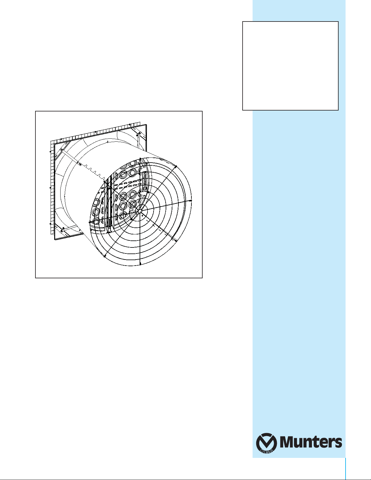
WM54F
Wall Mount Fan
Manual for use and maintenance
including assembling instructions
with Damper Door
+CE Declaration of conformity
WM54 Fiberglass Wall Mount Fan
wi
th Damper Door
Air extraction fan
A
g/MIT/UmGB-2483-07/17 Rev 1.0
1
Page 2

WM54F Fiberglass Wall Mount Fan with Damper
Manual for use and Maintenance
Thank You:
Thank you for purchasing a Munters WM54F Fiberglass with Damper! Munters equipment is designed to be the
highest performing, highest quality equipment you can buy. With the proper installation and maintenance it will
provide many years of service.
Please Note:
To achieve maximum performance and insure long life from your Munters product it is essential that it be installed
and maintained properly. Please read all instructions carefully before beginning installation.
This manual for use and maintenance is an integral part of the apparatus together with the attached technical
documentation and has been produced with reference to Directive 2006/42/EC, paragraph A, Annex II, and
to ErP Directive 2009/125/CE Commission Regulation 327/2011.
This document is destined for the user of the apparatus: it may not be reproduced in whole or in part, committed
to computer memory as a file or delivered to third parties without the prior authorisation of the assembler of the
system. Munters Italy S.p.A. reserves the right to effect modifications to the apparatus in accordance with
technical and legal developments and to make alterations to specifications, quantities, etc.,for production or
other reasons, subsequent to publication.
Conditions and Limitations:
Products and Systems involved in a warranty claim under the “Warranty Claims and Return Policy” shall have
been properly installed, maintained and operated under competent supervision, according to the instructions
provided by Munters.
Malfunction or failure resulting from misuse, abuse, negligence, alteration, accident or lack of proper installation
or maintenance shall not be considered a defect under the Warranty.
2
Page 3

Index
Chapters Page
1. CE Declaration
2. Unpacking the Equipment
2.1 Parts List
2.2 Fan Dimensions
2.3 Tools for Installation
3. Installation Instructions
3.1 Install
3.2 Damper Door Installation
3.3 Cone Installation
3.4 Motor Mounting
4. Electrical Wiring
4.1 Recommended Wiring
5. Operation
4
6
6
8
8
9
9
15
18
26
27
28
29
6. Maintenance
7. Winterizing
7.1 Winterizing
7.2 Winter Weather Protection
8. Troubleshooting
9. Exploded View and part list
10. Warranty
WARNING
!!
All the components and spare parts MUST be storaged in dry and clean environment.
30
32
32
32
33
34
37
3
Page 4

CE Declaration
1.
CE Declaration of conformity
(complies with Subparagraph A Annex II Directive 2006/42/EC)
Munters Italy S.pA.
with registered officies in Strada Piani, 2 - 18027 Chiusavecchia (IM) - Italy
(Company Registration nr. 00081050080)
declares on its own responsability that the apparatus:
Designation
Model
Year of Manufacture
conforms with the essential safety requirements stated by Apparatus Directive 2006/42/EC
and performance requirements comply with the ErP Directive 2009/125/CE,
with particular reference to the following provisions: UNI EN 953:2009, UNI EN ISO 12100:2010,
UNI EN ISO 12499:2009, UNI EN ISO 13857:2008, CEI EN 60204-1:2006 (CEI 44-5)
Fan designed for moving air to control temperature
and humidity in livestock.
WM54F
2017
UNI EN ISO 5801:2009
Chiusavecchia, 5th July 2017
Marco Scomparin
Legal Representative
4
Page 5

CE DeclarationChapter 1
1.1 Disclaimer
Munters reserves the right to make alternations to specifications, quantities, dimensions etc. for production or
other reasons, subsequent to publication. The information contained
herein has been prepared by qualified
experts within Munters. While we believe the information is accurate and complete, we make no warranty or
representation for any particular purposes. The information is offered in good faith and with the understanding
that any use of the units or accessories in breach of the directions and warnings in this document is at the sole
discretion and risk of the user.
1.2 Introduction
In order to realize the full benefit from this product it is important that it is installed, commissioned and operated
correctly. Before installation or using the fan, this manual should be studied carefully. It is also recommended that it
is kept safely for future reference. The manual is intended as a reference for installation, commissioning and
day-to-day operation of the Munters fans.
1.3 Data for Fan Eco Design Directive
optional
Product information requirements* →
(according to ANNEX I -3.2 of regulation)
Fan description(*
WM54F 1.5hp 3ph 50Hz OS
WM54F 2hp 3ph 50Hz OS
* Fans tested are configured according to COMMISSION REGULATION (EU) No 327/2011 of 30th March 2011 - ANNEX II - 1.5. Efficiency values, according to
Commission Regulation (EU) 327/2011, refers to exhaust fans only.
)
1 2 3
Overall efficiency η%
Efficiency grade
3
9,3
A static
A
static
39,8
4
Measurement category
Efficiency category
44,9
44,4 35,4
34,4 no 1310 30562 60,71
5
Target efficiency grade 2015
no
6
a
VSD must be installed with the fan
Motor power input at optimum
1852
6b
Flow rate at optimum energy
energy efficiency [W]
3
4755 76,
6c
efficiency [m3/h]
Pressure at optimum energy
efficiency [Pa]
510 1
35 566 1
7
RPM at optimum energy efficiency
8
Speific ratio
5
Page 6

Unpacking the Equipment
2.1 Parts List
Each WM54F Fan Requires:
1 – 54” Fiberglass Orifice
1 – 54” Propeller
1 – Central Support
1 – Motor
1 – Motor Pulley
1 – Drip Shield
1 – Main Frame Assembly
1 – Plastic Door Assembly
4 – Plastic Cone Sections
1 – Round safety mesh
1 – Flat safety mesh
1 – Motor slide
1 – Tensioner Bracket
4 – Cone Support Brackets
4 – Cone/Strut Mounting Bracket
1 – V-Belt (A61)
1 – Hub with Bearings & Shaft
1 – Central pulley
1 – Tensioner Pulley
1 – Belt Tensioner
1 – Motor Stiffener Bracket
2 – Tension spring
1 – Cable
Bolts and nuts
2.
6
Page 7
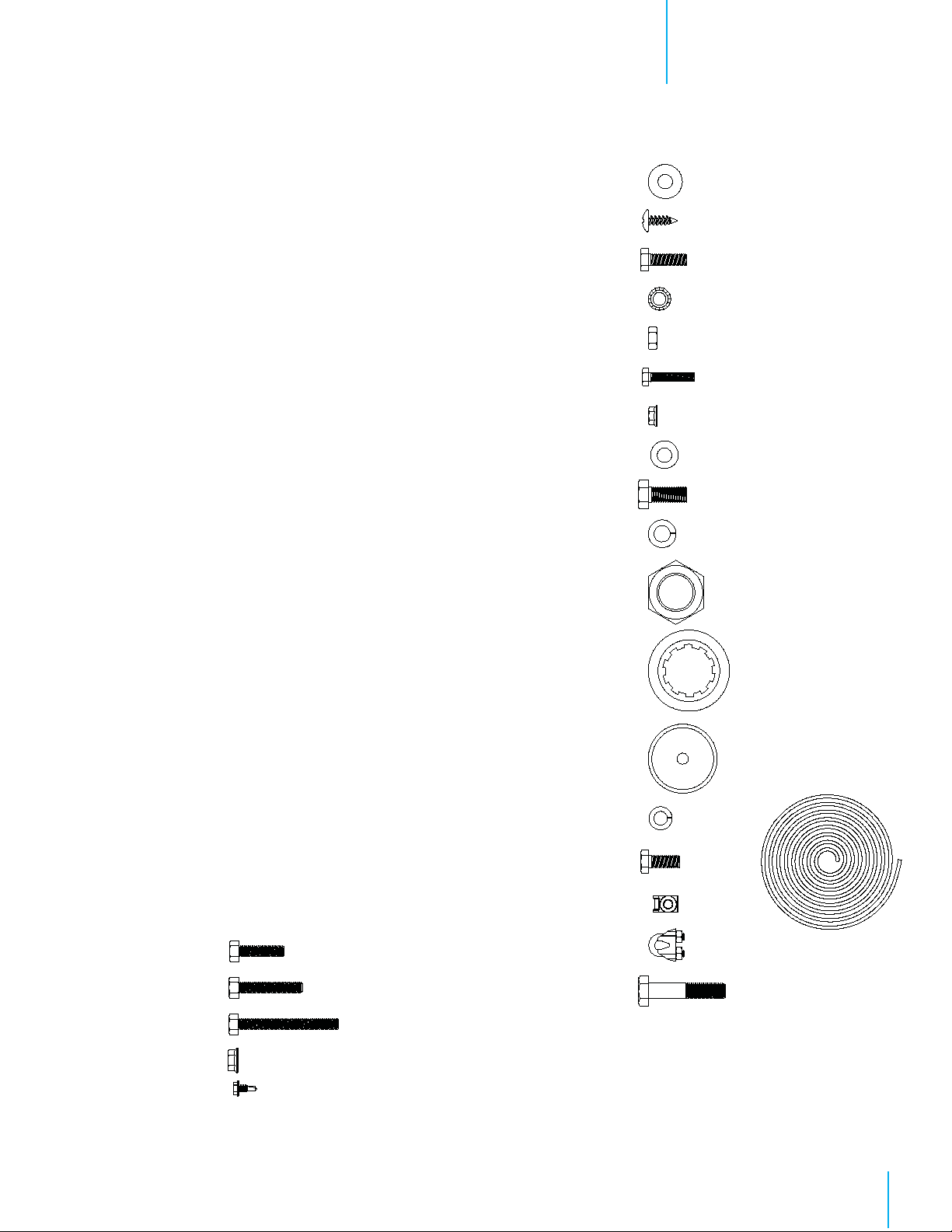
Bolts and nuts for 1 – WM54F Fan Installation
[A]….12 – Ø8x32 Washer
[B]…. 2 – Ø6.3x19 Self-tapping Screw
[C]…. 4 – M8x25 Hex Screw
[D]…. 4 – Ø8 Ext Toothed Washer
[E]…. 4 – M8 Hex Nut
[F]…. 4 – M6x30 Hex Screw
[G]…. 4 – M6 Hex Nut with Flange
[H]…. 4 – Ø8x24 Washer
[I]….. 1 – M10x25 Hex Bolt
[J]…. 1 – Spring Washer D10
[K]….. 1 – M25 Hex Nut
[L]…. 1 – Waterproof Distance Piece
[M]…. 1 – Cup Cover Nut
[N]…. 1 – Spring Washer D8
[O]…. 1 – M8x20 Hex Screw
[P]…..12 – Plastic Clip
[Q]…..1 – Cable
[R]…. 3 – Cable Clamp
[S]…. 1 – M10x50 Hex Bolt
Unpacking the EquipmentChapter 2
[A]
[B]
[C]
[D]
[E]
[F]
[G]
[H]
[I]
[J]
[AA]….18 – Ø8x30 Hex Screw
[BB]….. 4 – Ø8x45 Hex Screw
[CC]….. 7 – Ø8x65 Hex Screw
[DD]….37 – M8 Hex Nut with Flange
[EE]….. 4 – Ø4.8x13 Self-tapping Screw
[AA]
[BB]
[CC]
[K]
[L]
[M]
[N]
[O]
[P]
[R]
[S]
[Q
]
[DD]
[EE]
7
Page 8
Chapter 2
Unpacking the Equipment
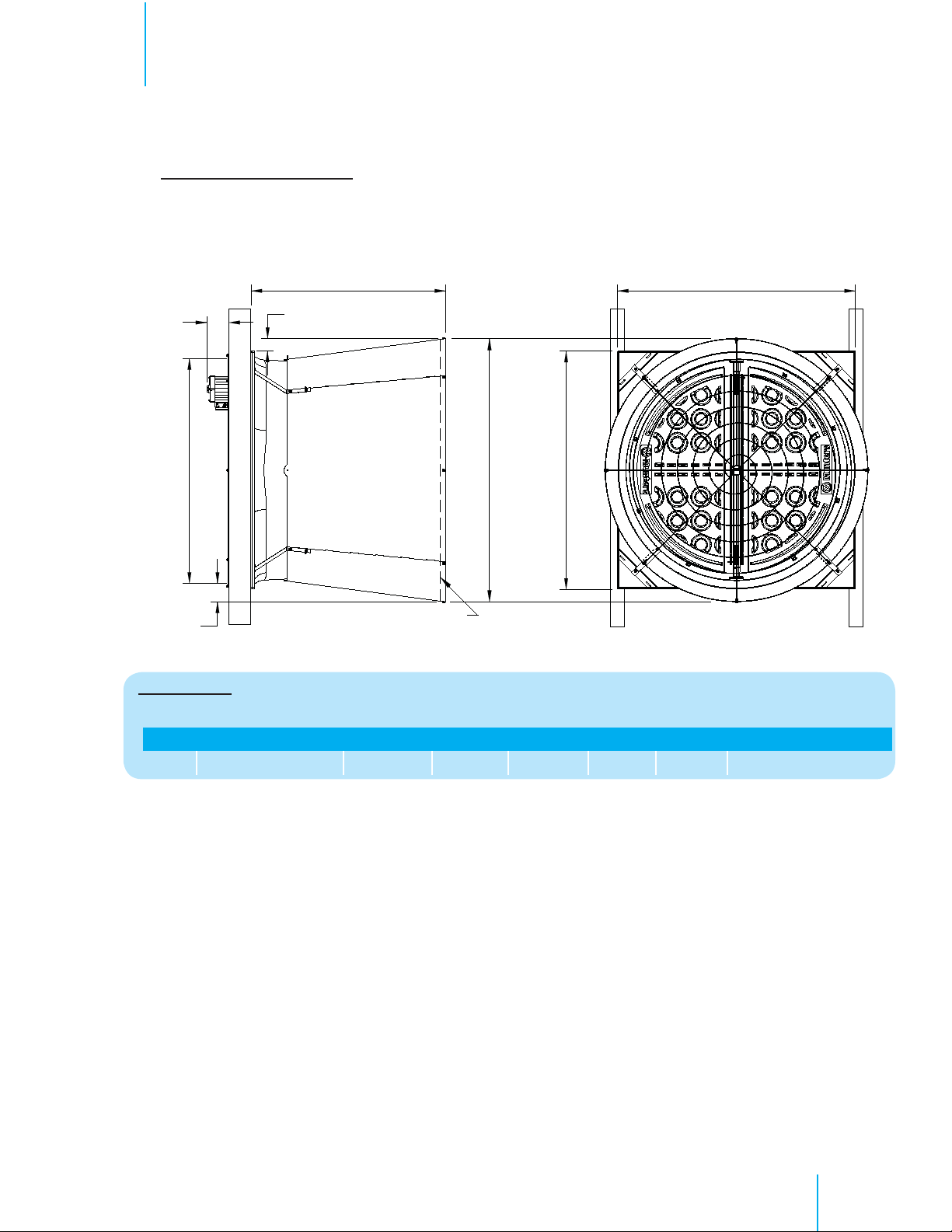
2.2 FAN DIMENSIONS
Fan Specifications: 50Hz shown
Voltage: 230/400 VAC
Phase: 3
AB
C
Wall Opening (W.O.)
F
E
A
D - Dia.
Guard
Dimensions:
Size A B C D - Dia. E F Wall Openings
54”
1524 x 1524
1245
185 max 1684 1435 x 1435
81
121
2.3 TOOLS REQUIRED FOR INSTALLATION
Pneumatic screwdriver
17mm Spanner
8mm Long Spanner
10mm Long Spanner
13mm Long Spanner
36mm Spanner
Screw Head Adaptor
Small Hammer
10mm Combination Spanner
Screwdriver
17mm Combination Spanner
8
Page 9
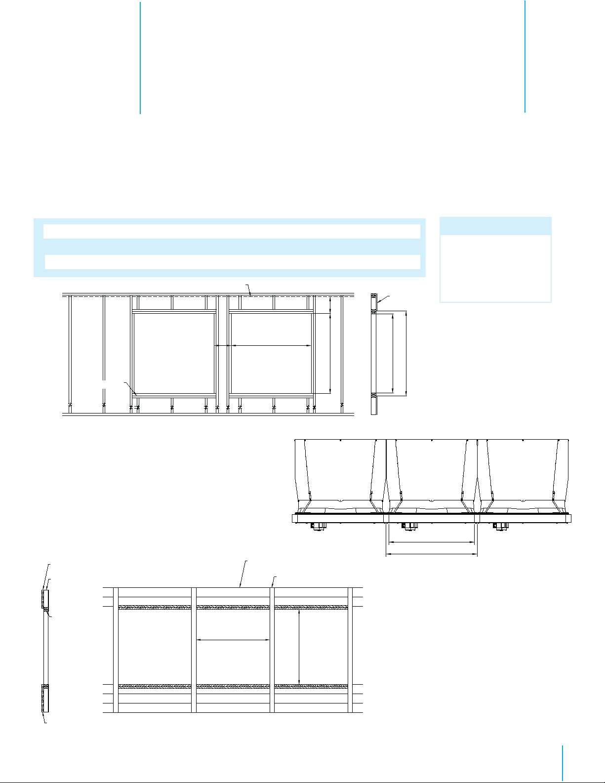
3.1 INSTALL
Step 1
Construct framed opening to correct size according to the Wall Opening listed in chart A below. See Figure 1A
and 1B. When installing exterior sheet metal before fan, leave 50mm of the framing exposed on all sides so the
orifice can mount flush to the frame.
Chart A
Installation Instructions
3.
Fan Dia.
54”
Wall Opening
(W. x H.)
1435 x 1435
Framing
Minimum Spacing
'Z'
305 recommended; 90 minimum
Ceiling
See minimum
spacing notes in
Chart A
Z
(see chart A)
Figure 1A Frame Construction
Center To Center
Dimension
1524
Minimum
Note:
Damper doors should
be carefully set aside
out of direct sunlight
until needed.
Stud Wall
305
W
H
(see chart A)
W x H Wall Opening
Sheet Metal Opening
Top View
50 x 200 Header boards
100 x 100 or
100 x 150 Posts
50 x 100
Framing
50 x 200 Banner boards
Figure 1B 100x100 Post Construction - Elevation View
W
(see chart A)
W
W O.C
Ceiling
100 x 100 or 100 x 150 Posts
H
(see chart A)
9
Page 10
Chapter 3
Installation Instructions
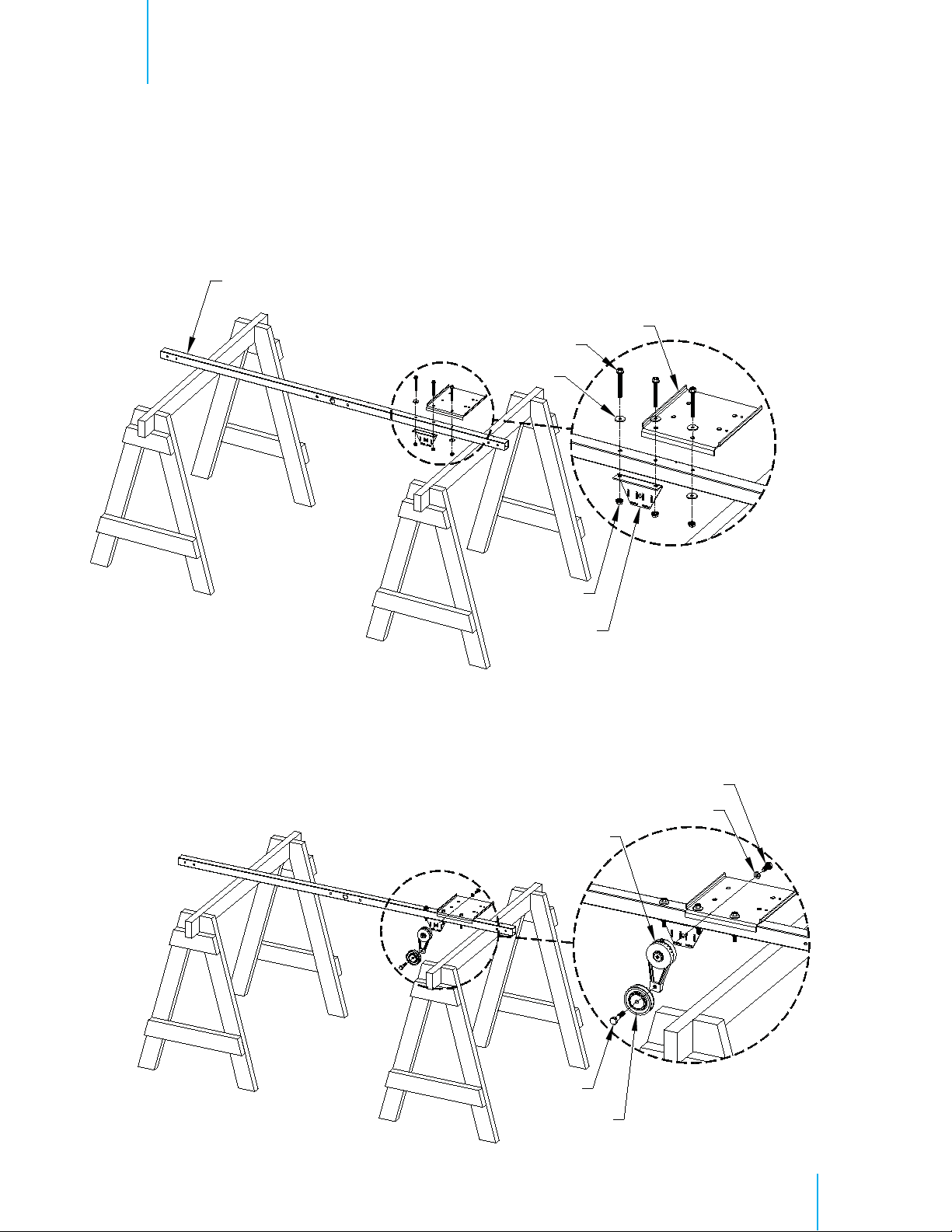
Step 2
Place the Central Support on saw horses or a flat work surface. The large center hole should be pointing
horizontally. Attach the Motor Slide and the Tensioner Bracket to the Central Support using (3) Long Bolts
[CC], (4) Washers [A] and (3) Nuts [DD]. The Motor Slide and the Tensioner Bracket share the middle
hole. See Figure 2A.
Central Support
Motor Slide
Long Bolts [CC]
Washer [A]
Nuts [DD]
Tensioner Bracket
Figure 2A
Step 2B
Attach the 3” Tensioner Pulley to the Belt Tensioner using Bolt [S]. Then attach the Belt Tensioner assembly
to the Tensioner Bracket using Bolt [I] and Washer [J]. Finger tighten only at this time. See Figure 2B.
Bolt [I]
Washer [J]
Belt Tensioner
Figure 2B
Bolt [S]
Tensioner Pulley
10
Page 11
Chapter 3
Installation Instructions
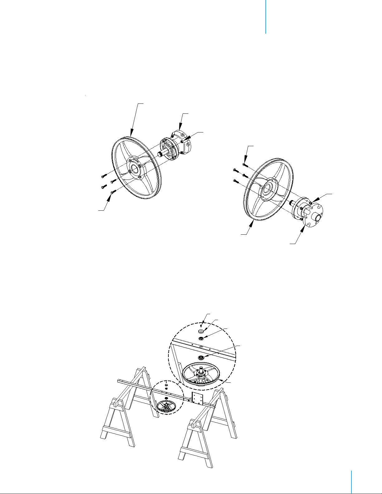
Step 3
Attach Central Pulley to Hub using (4) Bolts [F] and Nuts [G] and tighten to 14 Nm.. See Figure 3.
Central Pulley
Hub
Nut [G]
Bolt [F]
Bolt [F]
Nut [G]
Central Pulley
Figure 3
Hub
Step 4
Rotate the Central Support on the saw horses so the Motor Slide is pointing up. Then slide the Waterproof
Distance Piece [M] over the hub shaft as shown in Figure 4. Attached the Pulley/Hub Assembly to the
Central Support using (1) Hex Nut [K] and tighten to 60 Nm. See Figure 4. Then place the Cup Cover Nut
[M] over the Hex Nut and fasten in place with (1) Tapping Screw [B]. See Figure 4. Set aside the
Support Assembly for use in a later step.
Tapping screw [B]
Cap Cover [M]
Hex Nut [K]
Waterproof Distance Piece [L]
Hub Assembly
Figure 4
1
1
Page 12
Chapter 3
Installation Instructions
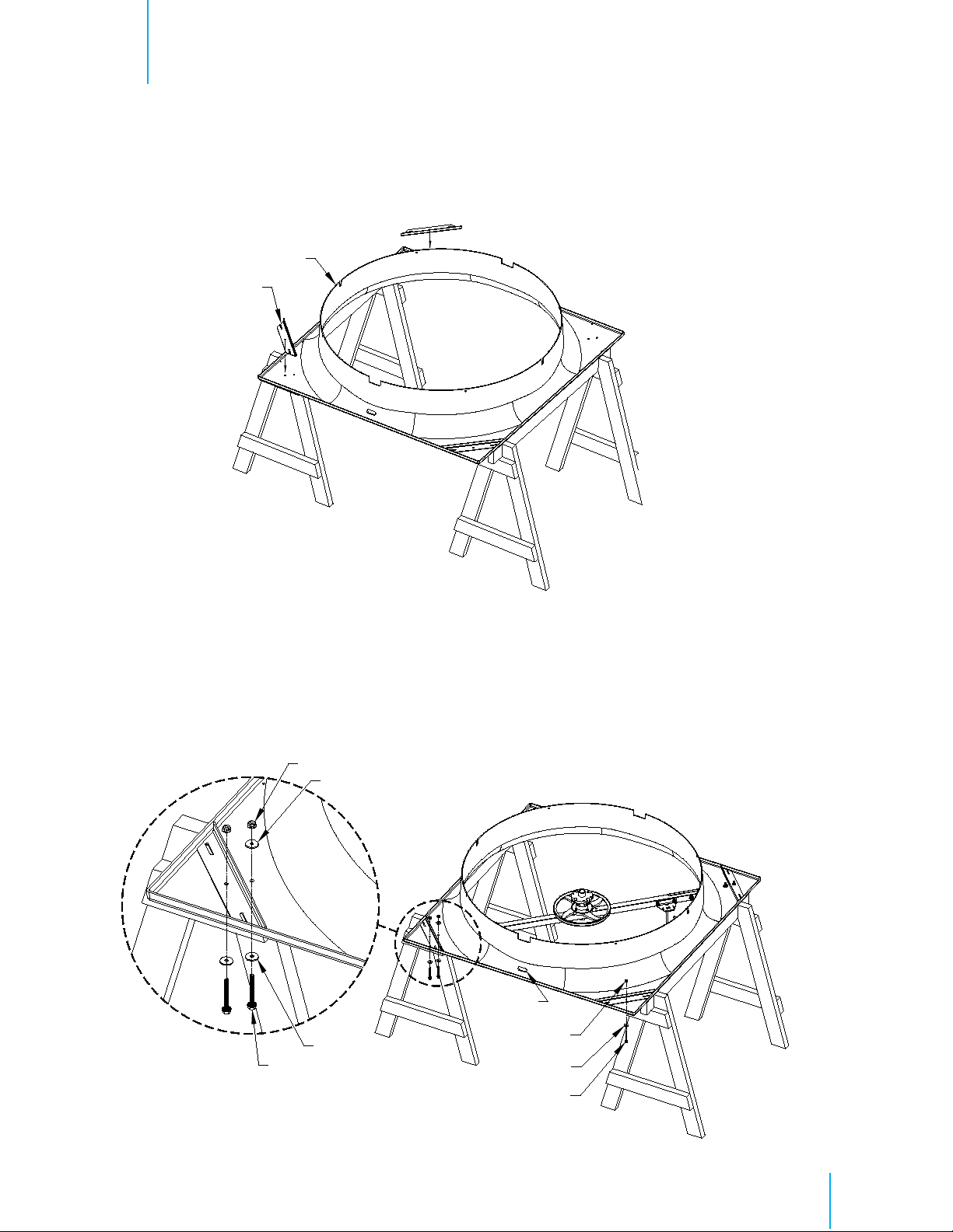
Step 5
Place Fiberglass Orifice on saw horses with the round orifice pointing up and place (1) Cone/Strut Mounting Bracket in
each corner of the Fiberglass Orifice. See Figure 5.
Fiberglass Orifice
Mounting Bracket
Figure 5
Step 6
The corners of the Fiberglass Orifice with 2 holes are the corners where the Support Assembly attaches. Attach the Support
Assembly using (4) Long Bolts [CC], (6) Washers [A] and (4) Nuts [DD] and in the opposite corners attach the Cone/Strut
Mounting Bracket to the orifice using Short Bolt [AA], Washer [A] and Nut [DD]. See Figure 6
Nuts [DD]
Washer [A]
Drain Hole
Washer [A]
Long Bolt [CC]
Nuts [DD]
Washer [A]
Figure 6
Short Bolt [AA]
12
Page 13

Chapter 3
Installation Instructions
Step 7
Attach Propeller to Hub Assembly using (4) Bolts [C], Washers [D] and Nuts [E] and tighten to 22 Nm. See
Figure 7.
Bolt [C]
Washer [D]
Propeller
Nut [E]
3.2 Damper Door Installation
Step 8
Slide the Main Frame Assembly onto the Fiberglass Orifice with the pin on the Main Frame opposite the
drain hole. See Figure 8A. Line up the 4 holes in the Main Frame with the holes in the orifice and fasten
using (4) Self-tapping Screws [EE]. See Figure 8B.
Main Frame
Pin
Figure 7
Hole in Fiberglass Orifi ce
Self-tapping Screw [EE]
Fiberglass Orifi ce
Drain Hole
Figure 8A
Figure 8B
13
Page 14

Chapter 3
Installation Instructions
Step 9
Attach Drip Shield to bottom of framed opening using (3) proper Screws (Not Provided). See Figure 9A and 9B. If a
100mm wall is used a support board must be installed as shown in Figure 9B. Be sure not to deform Drip Shield when
installing screws.
Barn Screw Barn Screw
(Not
Drip plate
Screw
Provided)
150mm Wall
Drip Shield
Figure 9A
Drip plate
Support board
Figure 9B
100mm Wall
Step 10
Locate the Drain hole in the Fiberglass Orifice. This is the bottom of the Orifice. Set the bottom edge of the panel on the
Drip Shield ledge and center the panel on the opening. Then secure the Orifice
to the wall using (16) proper Screws (Not
Provided). See Figure10A and 10B.
NOTE: the proper type of fixing screw has to be selected depending on the material of the wall of the installation.
Orifi ce Panel
Drain hole
Drip Shield ledge
Figure 10A
Screws (Not Provided)
Figure 10B
14
Page 15

Chapter 3
Installation Instructions
Step 11A
Carefully remove folded door assembly from box. Open the doors enough to reach the latch pin and pull it down until the end
of the latch pin is flush with the top of the doors. Make sure the Long Hinge Pin does not fall out. See Figure 11A
Latch Pin
Figure 11A
15
Page 16

Chapter 3
Installation Instructions
Step 11B
Being careful not to let pin fall out, set Doors into Main Frame with the Hinge Pin in the hole at the bottom
plate of the Main Frame and push the top of the Doors into place. See Figure 11B.
Door
Hinge Pin
Figure 11B
Step 11C
Separate the doors and push them into the closed position. Now push Latch Pin up into place, then turn
the short leg of the Latch Pin into place against the door and secure in place using Self-tapping screw [B].
Latch Pin should extend up through the upper plate in the Main Frame. See Figure 11C.
Latch Pin
Latch Pin Leg
Self-tapping Screw [B]
Figure 11C
16
Page 17

Step 12A
Find the Cable [Q], insert it into the small hole
ferrule stops at the plate. See Figure 12A.
Chapter 3
Installation Instructions
in the upper plate of the Main Frame and pull it through until the
Cable [Q]
Hole in Main frame
Figure 12A
Step 12B
On the room side of each door drill a 3mm dia. Hole in each door through the center of the middle dimple
shown. See Figure 12B.
Drill Dimple
Figure 12B
17
Page 18

Chapter 3
Installation Instructions
Step 12C
From the inside attach each of the Tension Springs to the hole in the upper plate of the Main Frame using
the end of the spring with the loop, then stretch the spring and insert the other end of the spring into the hole
drilled in the door in the previous step. See Figure 12C
Hole in upper plate
Drilled Hole in Damper Door
Tension Spring
3.3 Cone Installation
Step 13
Place all 4 cone sections on a flat surface with the tabs from one facing the slots of the next. See Figure 13A.
Curl up the tab end of the first cone section and insert the tabs up into the slots in the next cone section, a
mallet may be needed to seat the slots over the tabs completely. See Figure 13B. Repeat this step until all
4 cone sections are connected and laying flat
Figure 12C
Figure 13A
Figure 13B
1
8
Page 19

Chapter 3
Installation Instructions
Step 14A
Fasten each of the joints in the single outer hole using (1) Short Bolt [AA], Washer [A] and Nut [DD], with
the nut on the side with the tabs. At the inner pair of holes of each joint attach (1) Cone Support Bracket
to the inner hole using (1) Bolt [AA], Washer [A] and Nut [DD] with the bolt head on the side with the
tabs. See Figure 14A.
Nut [DD]
Washer [A]
Outer holes
Short Bolt [AA]
Short Bolt [AA]
Washer [A]
Inner holes
Nut [DD]
Cone Support Bracket
Figure 14A
Step 14B
Stand the cone sections on end and curl ends around to form cone with the Cone Support Bracket on the outside
and the tabs on the inside. Then insert the remaining tabs into slots so the tabs are inside the cone and fasten
final joint using (1) Short Bolt [AA], Washer [A] and Nut [DD], with the nut on the inside of the cone. At the
inner pair of holes
attach (1) Cone Bracket to the inner hole using (1) Short Bolt [AA], Washer [A] and Nut
[DD] with the bolt head on the outside of the cone. See Figure 14B.
Figure 14B
Short Bolt [AA]
Washer [A]
Cone Bracket
Nut [DD]
Short Bolt [AA]
Washer [A]
Nut [DD]
19
Page 20

Chapter 3
Installation Instructions
Step 15A
Install cone onto fan by putting the top of the cone over the top of the fan. The hole in the tab of the upper cone
section should slide down over the pin in the Main Frame assembly, then allow the rest of the cone to slide over
the rest of the orifice panel making sure the cone brackets remain on the outside of the cone. See Figure 15A.
Hole in Tab of Cone Section
Frame Pin
Figure 15A
Step 15B
Place the end of the Cone Brackets with the single hole over the bolt holding the Cone/Strut Mounting Bracket
to the orifice and secure with Nut [DD]. See Figure 15B. Secure the Cone to the Fan installing Medium Bolt
[BB] and Washer [A] through the remaining hole in the Cone Brackets and fastening with Nut [DD]. A long
screwdriver may be needed to help align the holes through the Cone Bracket, Cone, Damper Frame and
Orifice. See Figure 15B..
Nut [DD]
Medium Bolt [BB]
Washer [A]
Nut [DD]
Figure 15B
20
Page 21

Chapter 3
Installation Instructions
Step 16
Insert guard into cone with the eyelets facing you. Install eyelets over bolts already installed in cone and fasten
with Nut [DD] and then secure remaining eyelets using Short Bolt [AA], Washer [A] and Nut [DD]. See Figure
16.
Previously installed - Bolt and Nut
Nut [DD]
Short Bolt [AA]
Washer [A]
Nut [DD]
Figure 16
Step 17
Loop Cable [Q] that was installed in a previous step, around the lower, middle joint in guard and fasten to itself
with Cable Clamp [R]. Make sure cable is pulled snug. See Figure 17.
Cable Clamp [R]
Cable [Q]
Figure 17
21
Page 22

Chapter 3
Step 18
If Fans are to be installed 1524mm O.C., cut the 3 o’clock and 9 o’clock guard wire in the position
shown and push the side of the cone in as far as possible and fasten the cut guard wire to the attached guard
wire using Clamp [R]. See Figure 18.
Installation Instructions
Cut Guard Wire Here
3.4 Motor Installation
Step 19
Find the Key provided with the Motor and place it in the Keyway on the motor shaft. Place the Motor Pulley on
the Motor shaft with the hub facing towards the motor. See Figure 19. Tighten the Motor Pulley using Bolt [O]
and Washer [N].
Motor
Clamp [R]
Figure 18
Sheave
Washer [N]
Motor Key
Bolt [O]
Figure 19
22
Page 23

Step 20
Set the Motor on the Motor Slide. See Figure 20
Braket Slots
Chapter 3
Installation Instructions
Figure 20
Step 21A
Secure Motor to Motor Slide and motor bracket stiffener using (4) Bolts [AA], Washers [H] and Nuts [DD].
The rear upper bolt is where the motor bracket stiffener is attached. See Figure 21A.
Stiffener
Bolts [AA]
Washer [H]
Nuts [DD]
Figure 21A
23
Page 24

Chapter 3
Installation Instructions
Step 21B
Using channel locks and/or a hammer twist the motor bracket stiffener so that the holes in the bracket lay flat against the
framing. Then attach bracket to framing using (1) proper Screw (Not Provided). See Figure 21B.
NOTE: the proper type of fixing screw has to be selected depending on the material of the wall of the installation.
Frame
Stiffener
Screw (not provided)
Level
Motor Pulley
T
ensioner Pulley
Pulley
Central
Figure 21B
Step 22
Use a straight edge or level to check the alignment of
the Central Pulley, Tensioner Pulley and the Motor
Pulley. T
ighten the set screw to 9 Nm. See
22.
Step 23A
Slide V-belt over Propeller and install by wrapping
it around the 2 smaller pulleys and starting it over the
larger pulley, continue rolling it onto the larger pulley
until it fits onto pulley. See Figure 23A.
Figure 22
Figure
Figure 23A
4
2
Page 25

Chapter 3
Step 23B
Installation Instructions
To adjust the belt tensioner to the proper setting, loosen 10 mm bolt (using 17mm spanner) to allow tensioner arm
to rotate. Turn spanner clockwise until the single mark on base of the belt tensioner is aligned with mark 2 on
the tensioner arm. Hold tensioner at this setting and tighten the 10mm bolt to 50 Nm. See Figure 23B.
Hex
10mm
Bolt
Step 24A
Take the flat mesh. See Figure 24A.
Figure 23B
1515
1566
Figure 24A
2
5
Page 26

Chapter 3
Installation Instructions
Step 24B
Place the mesh against the framing and fasten it in place using (12) Plastic clips [P] and proper Screws (Not Provided).
See Figure 24B.
NOTE: the proper type of fixing screw has to be selected depending on the material of the wall of the installation.
NOTE: The flat mesh can be installed in case of a thickness wall ≥ 120mm. For lower thicknesses, if the fan is at a height
of less than 2,7m from the ground, a dedicated mesh must be ordered separately.
Screw
Plastic Clip [P]
Figure 24B
6
2
Page 27

Electrical Wiring
4.
All wiring should be installed in accordance with all national and local electrical codes. Fans used to ventilate
livestock buildings or other rooms where continuous air movement is essential should be connected to individual
electrical circuits, with a minimum of two circuits per room. For electrical connection requirements, refer to
diagram on motor nameplate and to information enclosed with the Munters environmental control to be used.
Three Phase Fans: motor overload protection should be provided for each fan. A three-poles safety switch or slow
blow motor fuses must be used. See Figure 25.
If a frequency drive (inverter)
installation of line filters is recommended to reduce voltage spikes and harmonic distortion. Supplemental
motor overload protection is also recommended.
NOTE: A safety cut-off switch should be located adjacent to each fan.
L1
Three Phase
Power Supply for
Fan
L2
L3
G
is used, confirm that motors are rated for inverter duty at the voltage used. The
Saftey cut-off
switch
T1
T2
T3
G
Figure 25
Three Phase - Motor Overload Protection with Disconnect
KEY:
L1=Line 1
L2=Line 2
L3=Line 3
G=Ground
Three Phase
Power Out
to Fan Motor
2
7
Page 28

Chapter 4
4.1 Recommended Wiring
Step 1
Electrical Wiring
As the power cable exits the back of the motor form a drip loop and then run cable to power source. See
Figure 26A and 26B.
Drip loop
Drip loop
Figure 26A
Figure 26B
28
Page 29

Operation
4. Operation
1) INITIAL START-UP: With electrical power off, verify that the fan propeller
turns freely and that all fasteners are secure. Turn on electrical power and
confirm that the fan operates smoothly.
2) ADJUSTMENTS: Set the fan control to the temperature shown on your
Munters ventilation system drawing, or to a value which will provide the
desired environmental conditions.
Some models of our fans allow to adjust the number of revolutions through inverter ( also
called VFD). In case of adjustment made by VFD the installer has to pay particular attention
to the following aspects:
• it is necessary that the resistance of the ground line to which the equipment are
(about 15-20 ohm) in order to avoid high currents
WARNING
!
connected has a very low values
that can flow through the motor bearings and damage them.
• It is necessary to install the proper line filters, to avoid interference and allow proper
operation of the equipment.
• The minimum frequency of operation of the engines in the case of absence of a
forced external ventilation is 30 Hz. In the case of an operating frequency below 30
Hz is necessary to provide an external forced ventilation to the engine.
5.
!
WARNING
Moving parts, disconnect power
before servicing.
It is absolutely normal for the damper door not to open completely. The air flow is calculated in the
configuration with the two doors not completely open but with an angle of 20° between them.
Ambient temperature during operation
- 15°C / + 40 °C
Ambient humidity during operation
< 90%
29
Page 30

Maintenance
6. Maintenance
6.
The following inspection and cleaning procedures should be performed monthly:
Tools Needed for Maintenance:
Spanner 10mm, 13mm, 17mm, pneumatic screwdriver
1) INSPECT PROPELLER: Check that propeller is secure on drive hub and that
there are no signs of damage. The blades are of a self-cleaning design and should
not require maintenance.
2) CLEAN regularly for best results:
• FAN MOTOR: Remove any dust accumulation from motor using a brush or
cloth. (DO NOT use a pressure washer). A clean motor will run cooler and last
longer. At the same time, verify that the motor is secure in its mount.
• DAMPER: Carefully clean dust from damper door and frame so that damper
door opens and closes freely. A brush or cloth should be used.
• GUARD: Clean any dust or feathers from fan guards using a brush. Dirty guards can reduce
airflow.
3) CHECK FASTENERS: For safety, all fasteners should be inspected. Tighten any
loose connections.
!
WARNING
Moving parts, disconnect power
before servicing.
!
WARNING
High Voltage, disconnect power
before servicing.
4) INSPECT FAN CONTROL: With power disconnected, inspect all electrical connec-
tions. Wiring should be secure and in good condition. Remove any dust build-up
from control case and sensor using a soft brush or cloth. NEVER CLEAN
ELECTRICAL EQUIPMENT WITH A PRESSURE WASHER!
Keep motor body clean. Dust deposit on motor body will lead to overheating and failure of
WARNING
!!
WARNING
!!
bearings and motor itself.
Do not use water for motor cleaning. Use compressed air only. Water spraying will cause
rust inside the bearings and lead to their failure.
We recommend to avoid to use water for washing fans since the electric motors and the
bearings of the central hub and centrifugal system support might get damaged by water
infiltration.
In case there is an unbreakable need to use water for cleaning the fans, the electric motor,
the central hub and the centrifugal weight mechanism have to be adequately protected by
water sprays.
30
Page 31

Chapter 6
Maintenance
5) CHECKING PULLEYS: Roll the belt off and look at both pulleys. If the pulley has grooves in it or
is no longer smooth, it needs replacement. A loose or slipping belt will reduce fan performance up
to 60% and cause premature belt failure.
Smooth
Pulley
6) BELT TIGHTENING:
17mm
spanner) to allow tensioner arm to rotate. Turn
Grooved
Pulley
To adjust the belt tensioner to the proper setting, loosen 10 mm bolt (using
spanner clockwise until the single mark on
base of the belt tensioner is aligned with mark 2 on the tensioner arm. Hold tensioner at this
setting and tighten the 10mm bolt to 54 Nm.
!
WARNING
Do not power wash
electrical devices.
!
WARNING
Moving parts, disconnect
power before servicing.
Hex on tensioner
10mm
Bolt
Alignment Mark
on Base
Mark 2 on Tensioner Arm
31
Page 32

Winterizing
7.
7.1 Winterizing
In most climates, it is probable that the ventilation system will never need to operate at a total capacity
during the colder winter months. Consequently, it is advisable to “winterize” those fans which will not
be used in cold weather to avoid unnecessary heat loss and condensation.
To winterize, turn fan control “off”. Install the insulated closure panel over the fan intake. If you don’t
have an insulated closure panel, a piece of rigid insulation material can be used. Remember the
insulation panel must be removed before warmer weather returns.
NOTE: At least one single speed fan should be left uncovered and with power available to provide air
movement in the event of variable speed control difficulties.
7.2 Winter Weather Protection
To prevent cone or fan damage from snow or ice sliding off building roof, weather protection must be
provided. A weather shelter may be constructed to cover the entire fan, See Figure 27, or snow guards
may be placed on the roof, See Figure 28.
Figure 27
Provide Weather
Shelter Over Fans
150mm Min.
Fan with
Discharge Cone
Snow Guards located
per manufacturers
recommendations
Ceiling
Fan with
Discharge
Cone
Figure 28
!
IMPORTANT
Munters Product and System
Warranties do not cover cone or fan
damage from external sources.
Note: Snow guards are designed to prevent sudden, dangerous snow
and ice slides when attached to the building roof according to
manufacturers recommendations. The supplier listing above is given
as a reference only. Munters does not endorse any specific snow
guard product and no performance warranty is implied.
32
Page 33

Troubleshooting
7.1 Troubleshooting
8.
!
WARNING
High Voltage, disconnect power
before servicing.
SYMPTOM
Fan Not Operating
Fan OperatingInsuffi cient Airfl ow
Excessive Noise
!
WARNING
Moving parts, disconnect power
before servicing.
POSSIBLE CAUSES
1. Fan control set above room
temperature
2. Blown fuse or open circuit breaker
3. Propeller blade contacting fan housing
4. Fan control defective
5. Motor defective
1. Damper door jammed
2. Guard dirty
1. Propeller blade contacting fan housing
!
WARNING
Moving parts, disconnect
power before servicing.
CORRECTIVE ACTION
1. Set to a lower temperature
2. Replace fuse or reset breaker
3. Realign motor in fan housing
4. Repair or replace control
5. Repair or replace motor
1. Clean damper door & fan housing
2. Clean guard
1. Sand fan housing to remove high spot
Excessive
Vibration
Fan Never Turns
Off
It is normal that the damper does not open completely. No corrective actions are needed.
1. Motor loose on mount
2. Propeller damaged
3. Motor or propeller shaft bent
1. Override thermostat set incorrectly
2. Control set for continuous operation
1. Tighten fasteners
2. Replace propeller
3. Repair or replace motor or propeller shaft
1. Set to the correct temperature
2. Set control correctly
33
Page 34

Exploded View
18
1
2
9.
17
16
Fan Components
3
4
5
6
7
13
12
8
9
11
10
14
15
34
Page 35

19
Exploded ViewChapter 8
20
21
22
23
24
Damper/Cone Components
5
3
Page 36

Parts ListChapter 8
Item
1
2
3
4
5
6
7
8
9
10
11
12
13
14
15
16
17
18
19
20
21
22
23
24
Catalog No
WM54F
2200761 Fiberglass orifice
2515360 Propeller
2245861 V-belt (A61)
2465692
2248001 Central pulley
2472000 Waterproof distance piece
2273600 M25 Hex nut
2248711
2446040 Motor stiffener
2446010 Motor slide
2447080 Belt tensioner bracket
2515362-K Belt tensioner assembly with 3” pulley
2234035 3” tensioner pulley
2234050 Belt tensioner
2268110 Plastic clip 1
2200767 Flat safety mesh
273707P
2
2446030 Drip shield
2446020
2200763
2200762 Cone sector
2446050
2200765 Door Assembly 2
2200765 Main Frame Assembly
2200766 Tension spring
.
Part Name/Description
Hub with bearing and shaft 1
Motor pulley
*
Motor
entral support
C
one/Strut mounting
C
Round safety mesh
Cone support bracket
bracket
1
1
1
1
1
1
1
1
1
1
1
1
1
1
2
1
1
1
4
1
4
4
1
2
* The motor code changes depending on the configuration utilized.
3
6
Page 37

Warranty
10.
Warranty and technical assistance
Munters products are designed and built to provide reliable and satisfactory performance but cannot
be guaranteed free of faults; although they are reliable products they can develop unforeseenable
defects and the user must take this into account and arrange adequate emergency or alarm systems if
failure to operate could cause damage to the articles for which the Munters plant was required: if this
is not done, the user is fully responsible for the damage which they could suffer.
Munters extends this limited warranty to the first purchaser and guarantees its products to be free from
defects originating in manufacture or materials for 1 year from the date of delivery, provided that
suitable transport, storage, installation and maintenance terms are complied with. The warranty does
not apply if the products have been repaired without express authorisation from Munters, or repaired
in such a way that, in Munters’ judgement, their performance and reliability have been impaired, or
incorrectly installed, or subjected to improper use. The user accepts total responsibility for incorrect use
of the products.
The warranty on products from outside suppliers fitted to Breeze fan, (for example electric motors, etc.)
is limited to the conditions stated by the supplier: all claims must be made in writing within eight days
of the discovery of the defect and within 12 months of the delivery of the defective product. Munters
has thirty days from the date of receipt in which to take action, and has the right to examine the
product at the customer’s premises or at its own plant (carriage cost to be borne by the customer).
Munters at its sole discretion has the option of replacing or repairing, free of charge, products which it
considers defective, and will arrange for their despatch back to the customer carriage paid. In the
case of faulty parts of small commercial value which are widely available (such as bolts, etc.) for
urgent despatch, where the cost of carriage would exceed the value of the parts, Munters may
authorise the customer exclusively to purchase the replacement parts locally; Munters will reimburse
the value of the product at its cost price.
Munters will not be liable for costs incurred in demounting the defective part, or the time required to
travel to site and the associated travel costs. No agent, employee or dealer is authorised to give any
further guarantees or to accept any other liability on Munters’ behalf in connection with other Munters
products, except in writing with the signature of one of the Company’s Managers.
!
WARNING In the interests of improving the quality of its products and services, Munters reserves
the right at any time and without prior notice to alter the specifications in this manual.
The liability of the manufacturer Munters ceases in the event of:
• dismantling the safety devices;
• use of unauthorised materials;
• inadequate maintenance;
• use of non-original spare parts and accessories.
37
Page 38

WarrantyChapter 10
Barring specific contractual terms, the following are directly at the user’s expense:
• preparing installation sites;
• providing an electricity supply (including the protective equipotential
bonding (PE) conductor, in accordance with CEI EN 60204-1,
paragraph 8.2), for correctly connecting the equipment to the mains
electricity supply;
• providing ancillary services appropriate to the requirements of the plant
on the basis of the information supplied with regard to installation;
• tools and consumables required for fitting and installation;
• lubricants necessary for commissioning and maintenance.
It is mandatory to purchase and use only original spare parts or those recommended by the
manufacturer.
Dismantling and assembly must be performed by qualified technicians and according to the
manufacturer’s instructions.
The use of non-original spare parts or incorrect assembly exonerates the manufacturer from all liability.
Requests for technical assistance and spare parts must be made directly to the manufacturer, at the
following address:
Munters Italy S.p.A
Strada Piani, 2
18027 Chiusavecchia (IM), Italy
Tel: +39 0183 52 11
Fax: +39 0183 521 333
info@munters.it
3
8
Page 39

Ag/MIT/UmGB-2483-07/17 Rev 1.0
www.munters.com
Australia Phone + 61 2 8843 1594, agh.info@munters.com.au, Brazil Phone +55 41 3317 5050, contato@munters.com,
Canada Phone +1 517 676 7070, aghort.info@munters.com, China Phone +86 10 8048 3493, marketing@munters.cn,
Denmark Phone +45 98 623 311, aghort@munters.dk, India Phone +91 20 6681 8900, info@munters.in, Indonesia
Phone +66 2 642 2670, info@munters.co.th, Italy Phone +39 0183 5211, info@munters.it, Japan Phone +81 3 5970
0021, mkk@munters.jp, Korea Phone +82 2 7618 701, munters@munters.co.kr, Mexico Phone +52 818 2625 400,
dhinfo@munters.com, Singapore Phone +65 7 446 828, info@munters.com.sg, South Africa and Sub-Sahara Countries
Phone +27 11 997 2000, info@munters.co.za Spain Phone +39 0183 5211, info@munters.it, Sweden Phone +46 8
6266 300, info@munters.se, Thailand Phone +66 2 6422 670, info@munters.co.th, Turkey Phone +90 262 7513 750,
info@muntersform.com, USA Phone +1 517 676
7070, aghort.info@munters.com, Export & Other countries Phone +39
0183 5211, info@munters.it
Munters reserves the right to make alterations to specifications, quantities, etc., for production or other reasons, subsequent to publication.
© Munters AB, 2015
39
 Loading...