

Page 1
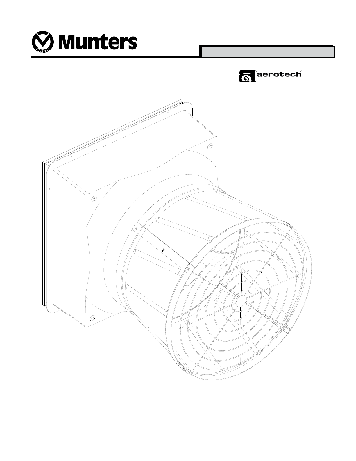
26" Vortex® Fans
R
Ventilation Systems
R
VX26F1CR • VX26F1CP
U.S. Patent No. 6386828, 6616404 and 6953320.
Munters Corporation
4215 Legion Dr. Mason, MI 48854-1036 USA
(517) 676-7070 Fax (517) 676-7078
www.munters.us/aerotech
FORM: QM1070
Rev.3, February 2010
Page 1 of 15
Page 2

USER'S MANUAL and INSTALLATION GUIDE
TABLE OF CONTENTS
Section
Unpacking the Equipment ........................................................................................................3
Dimensions ...............................................................................................................................3
Installation Instructions ........................................................................................................... 4-7
"PR" Style Shutters ...................................................................................................................8
"PV" Style Shutters ...................................................................................................................9
Electrical Wiring .......................................................................................................................10
Maintenance ............................................................................................................................ 11
Trouble Shooting .....................................................................................................................12
Winterizing Fan........................................................................................................................13
Winter Weather Protection ......................................................................................................13
Exploded View ...................................................................................................................... 14-15
Page
Thank You
Thank you for purchasing an Aerotech Vortex fan. Aerotech equipment is designed to be the highest
performing, highest quality equipment you can buy. With the proper installation and maintenance, it
will provide many years of service.
PLEASE NOTE
To achieve maximum performance and insure long life from your Curtain Machine, it is essential that it be
installed and maintained properly. Please read all instructions carefully before beginning installation.
WARRANTY
For Warranty claims information see the "Warranty Claims and Return Policy" form QM1021
available from the Aerotech Ventilation System, Munters Corporation ofce at 1-800-227-2376
or by e-mail at aerotech@munters.com.
Conditions and Limitations:
• Products and Systems involved in a warranty claim under the “Warranty Claims and Return
Policy” shall have been properly installed, maintained and operated under competent
supervision, according to the instructions provided by Aerotech Ventilation Systems,
Munters Corporation.
• Malfunction or failure resulting from misuse, abuse, negligence, alteration, accident or lack
of proper installation or maintenance shall not be considered a defect under the Warranty.
Munters Corporation
4215 Legion Dr. Mason, MI 48854-1036 USA
(517) 676-7070 Fax (517) 676-7078
www.munters.us/aerotech
FORM: QM1070
Rev.3, February 2010
Page 2 of 15
Page 3
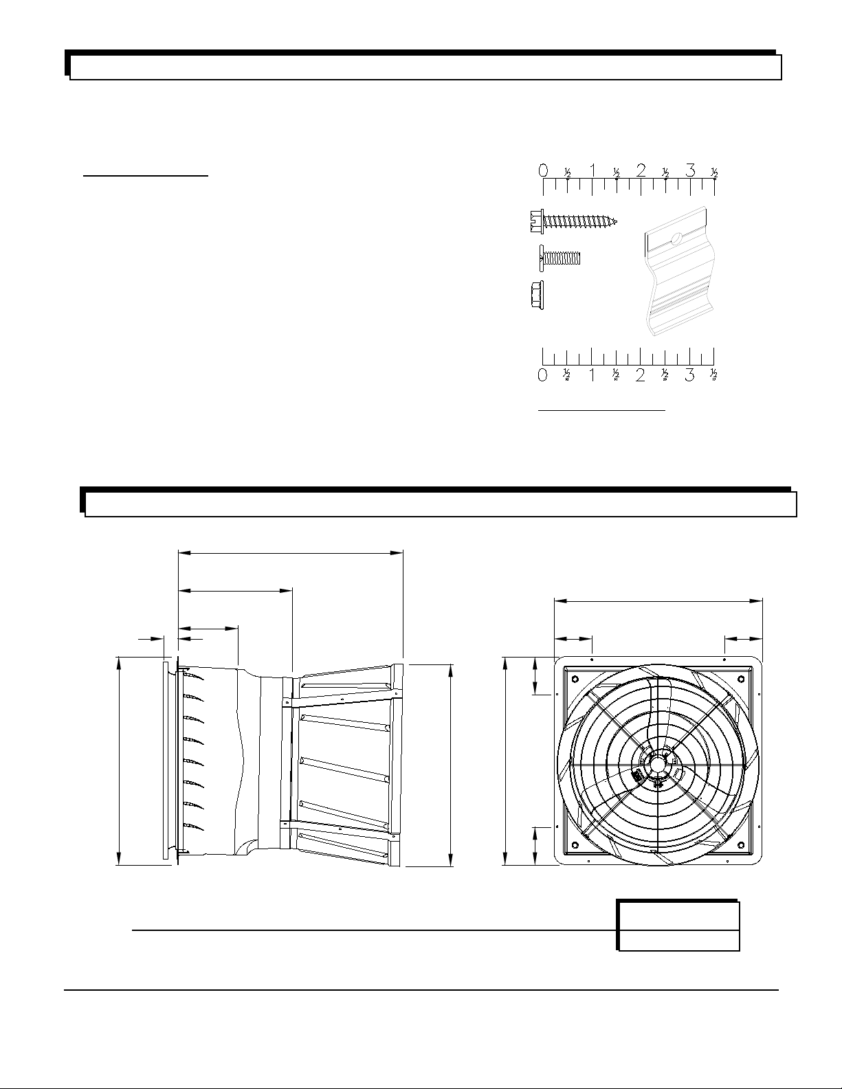
UNPACKING THE EQUIPMENT
Before beginning installation, check the overall condition of the equipment. Remove packing materials, and
examine all components for signs of shipping damage. Any shipping damage is the customer's responsibility
and should be reported immediately to your freight carrier. Fan is shipped complete with all accessories.
Remove shutter, guard and cone sections before proceeding with installation.
Each Fan includes:
1 - 26" Direct Drive Fan
1 - Shutter
4 - Cone Sections
1 - Guard
1 - Hardware Package as follows
HP1102 - 26" Vortex Fan, PR Shutter
[A] .... 8 - #14 x 1.5" Lag Screws
[B] .... 12 - 1/4" x 3/4" Wafer Head Bolts, S.S.
[C] .... 12 - 1/4" Hex Flange Nuts, S.S.
[D] .... 2 - Shutter Retainer Clips
HP1104 - 26" Fan, PV Shutter
[A] .... 8 - #14 x 1.5" Lag Screws
[B] .... 12 - 1/4" x 3/4" Wafer Head Bolts, S.S.
[C] .... 12 - 1/4" Hex Flange Nuts, S.S.
[A]
[B]
[C]
Fan Specifications:
Power: 120 or 240 VAC
Phase: 1
Hertz: 60
[D]
DIMENSIONS
H
C
E
F
G
I
C
A
B
B
D
A
FAN DIA.
26"
A
51/2"
B C
51/2"
33" 33" 353/4" 183/16" 91/2" 25/16" 321/16"
Munters Corporation
4215 Legion Dr. Mason, MI 48854-1036 USA
(517) 676-7070 Fax (517) 676-7078
www.munters.us/aerotech
D E F G H I
WALL OPENING
(I.D., framed)
301/4" sq.
FORM: QM1070
Rev.3, February 2010
Page 3 of 15
Page 4

INSTALLATION INSTRUCTIONS
Step 1
Construct the framed opening to correct size according to Wall Opening on Page 1. See Figure 1.
Ceiling
12"
12"
Wall Opening
(see page 1)
Framing
(see page 1)
Wall Opening
Figure 1
Step 2
Insert fan into the framed opening from the inside. Place (2) Fastener [D] under the top (2) Fastener [A]. See
Figure 2A. While lifting fan up tight to framing, fasten top of fan with the (2) Fastener [A] and [D]. See Figure
2B. Next, fasten bottom of fan, then both sides with remaining (6) Fastener [A]. Install ashing around opening
tight to fan and caulk around fan to seal. If fan and shutter needs to be mounted ush to inside wall, See
Figure 3 for framing details.
26" Vortex
Fan
#14 x 1.5" Lag
Screws [A]
Retainer
Clip [D]
2 x 4 Framing
Fan
Figure 2B
#14 x 1.5" Lag
Screws [A]
Retainer
Clip [D]
2 x 6 Framing
2 x 6
Framing
1 x 6 Framing
/4" W.
1
34" H. x 33
OUTSIDE
INSIDE
Figure 2A
Munters Corporation
4215 Legion Dr. Mason, MI 48854-1036 USA
(517) 676-7070 Fax (517) 676-7078
www.munters.us/aerotech
Figure 3
FORM: QM1070
Rev.3, February 2010
Page 4 of 15
Page 5

Step 3
Remove packaging from cone and guard sections.
Step 4
Place cone sections on ground with rounded side down. See Figure 4.
Munters Corporation
4215 Legion Dr. Mason, MI 48854-1036 USA
(517) 676-7070 Fax (517) 676-7078
www.munters.us/aerotech
Figure 1
FORM: QM1070
Rev.3, February 2010
Page 5 of 15
Page 6

Step 5
Stand (2) cone sections up and fasten with (2) Fastener [B] and [C] in the upper 2
holes. See Figures 5A and 5B. Finger tighten only.
Step 6
Stand next cone section up and fasten to previous cone sections as in Step 3. Stand last cone section up
and fasten on both sides be sure to only use the upper 2 holes. Finger tighten only.
¼" x ¾" Wafer
Head Bolt [B]
1
/4" x 3/4"
Wafer Head
Bolt [B]
1
/4" Flange Nut [C]
Cone Section
1
/4" Flange Nut [C]
Figure 5A
¼" x ¾" Wafer
Head Bolt [B]
1
/4" Flange Nut [C]
SIDE VIEW OF 2 CONE SECTIONS
Munters Corporation
4215 Legion Dr. Mason, MI 48854-1036 USA
(517) 676-7070 Fax (517) 676-7078
www.munters.us/aerotech
Figure 5B
FORM: QM1070
Rev.3, February 2010
Page 6 of 15
Page 7

Step 7
Lift cone assembly up and slide onto outlet of fan and
1
/4" Flange Nut [C]
fasten using (4) Fasteners [B] and [C]. See Figure 6.
Finger tighten only. Bolts must be installed from inside to
outside.
Fan Outlet
(Inside)
¼" x ¾" Wafer Head Bolt [B]
Cone Section
(Outside)
Figure 6
Step 8
Remove Fasteners [B] and [C] in outer holes. Insert guard into cone with the guard eyelets facing away from you.
Make sure each eyelet lines up with a hole in the cone sections, and secure with the (4) Fasteners [B] and [C],
previously removed. DO NOT tighten bolts at this time. See Figure 7A, 7B.
Fan
Step 9
Push cone sections together at each joint to tighten cone
around guard. Tighten wafer head bolts and nuts at all
joints, taking care not to overtighten. Tighten all bolts
holding guard in place.
If fan was ordered with 'PR' style shutter proceed to Step
10. If the 'PV' style shutter was ordered then proceed to
Step 12.
Cone
Guard
1
/4" Flange
Nut [C]
¼" x ¾" Wafer
Head Bolt [B]
Figure 7A
Cone
Sections
Guard
Eyelets at each joint
of Cone Sections
Munters Corporation
4215 Legion Dr. Mason, MI 48854-1036 USA
(517) 676-7070 Fax (517) 676-7078
www.munters.us/aerotech
Figure 7B
FORM: QM1070
Rev.3, February 2010
Page 7 of 15
Page 8

'PR' STyLE SHUTTER
Step 10
Insert Airfoil shutter into fan by sliding the top
ange of shutter under top retaining clips and
pressing bottom of shutter inward. See Figure 8.
Top
Retaining
Clip
Step 11
When shutter is in place, open shutter by pulling
down on tie-bar, reach into fan through the shutter blades and latch shutter in place with the draw
latches in 2 places. See Figure 9.
NOTE: Shutter protrudes from fan 215⁄16". Provide
adequate guarding to protect shutter.
Installation is now complete, proceed to
Electrical Wiring Section.
Airfoil
Shutter
Figure 8
Airfoil
Shutter
Munters Corporation
4215 Legion Dr. Mason, MI 48854-1036 USA
(517) 676-7070 Fax (517) 676-7078
www.munters.us/aerotech
Draw Latch
Figure 9
Airfoil
Shutter
FORM: QM1070
Rev.3, February 2010
Page 8 of 15
Page 9

'PV' STyLE SHUTTER
Step 12
Slide shutter into back of fan. See Figure 10A.
Fasten shutter in place by rotating the side and top
shutter clips over the shutter anges. See Figure
10B. Installation is now complete, proceed to
electrical wiring section.
PV Shutter
Figure 10B
Figure 10A
Munters Corporation
4215 Legion Dr. Mason, MI 48854-1036 USA
(517) 676-7070 Fax (517) 676-7078
www.munters.us/aerotech
FORM: QM1070
Rev.3, February 2010
Page 9 of 15
Page 10

ELECTRICAL WIRING
Recommended Wire Routing:
As the power cable exits the back of motor
form a drip loop and then run power cable
down along motor mount and "Zip" tie the cable
to motor mount to prevent cable from getting
tangled in the prop. See Figure 11. Then run
the cable out the drain hole to the circuit breaker or control panel.
(Continued on next page
).
Figure 11
!
WARNING
High Voltage,
disconnect power
before installation.
120 or 240 VAC
Power Supply for Fan
All wiring should be installed in accordance with National, State, and Local electrical
codes. Fans used to ventilate livestock buildings or other rooms where continuous
air movement is essential should be connected to individual electrical circuits, with a
minimum of two circuits per room. For electrical connection requirements, refer to diagram
on motor nameplate and to information enclosed with the Aerotech environmental control
to be used.
Single Phase Fans: motor overload protection should be provided for each fan. A Circuit
Breaker Switch or slow blow motor type fuses must be used See Figure 12. See Aerotech
form QM1400 for proper size.
NOTE: A safety cut-off switch should be located adjacent to each fan.
L1 (H)
L2 (N)
G
L1 (H)
L2 (N)
T1 (H)
T2 (N)
T1 (H)
T2 (N)
120 or 240 VAC
Power Out to Fan
G
Figure 12
Single Phase - Motor Overload Protection with Disconnect
(SY2000 or Equivalent)
NOTE: Information in parenthesis
refers to 120 VAC control.
KEY:
L1 = Line 1
L2 = Line 2
L3 = Line 3
Munters Corporation
4215 Legion Dr. Mason, MI 48854-1036 USA
(517) 676-7070 Fax (517) 676-7078
www.munters.us/aerotech
H = Hot
N = Neutral
G = Ground
FORM: QM1070
Rev.3, February 2010
Page 10 of 15
Page 11

MAINTENANCE
!
WARNING
High Voltage,
disconnect power
before servicing.
!
WARNING
Moving parts,
disconnect power
before servicing.
!
WARNING
The following inspection and cleaning procedures should be performed monthly:
1) INSPECT PROPELLER: Check that propeller is secure on motor shaft and that there
are no signs of damage. The blades are of a self-cleaning design and should not
require maintenance.
2) CLEAN regularly for best results:
• FAN MOTOR: Remove any dust accumulation from motor using a brush or cloth.
(DO NOT use a pressure washer). A clean motor will run cooler and last longer.
At the same time, verify that the motor is secure in its mount.
• SHUTTER: Carefully clean dust from shutter blades and frame so that shutter
opens and closes freely. A brush or cloth should be used.
• GUARD: Clean any dust or feathers from fan guards using a brush. Dirty guards
can reduce airow.
3) CHECK FASTENERS: For safety, all fasteners should be inspected. Tighten any
loose connections.
4) INSPECT FAN CONTROL: With power disconnected, inspect all electrical
connections. Wiring should be secure and in good condition. Remove any dust
build-up from control case and sensor using a soft brush or cloth. NEVER CLEAN
ELECTRICAL EQUIPMENT WITH A PRESSURE WASHER!
Do not power
wash.
Munters Corporation
4215 Legion Dr. Mason, MI 48854-1036 USA
(517) 676-7070 Fax (517) 676-7078
www.munters.us/aerotech
FORM: QM1070
Rev.3, February 2010
Page 11 of 15
Page 12

TROUBLE SHOOTING
!
WARNING
High Voltage,
disconnect power
before servicing.
SYMPTOM
Fan Not Operating
Fan Operating-
Insufcient
Airow
!
WARNING
Moving parts,
disconnect power
before servicing.
POSSIBLE CAUSES
1. Fan control set above room
temperature
2. Blown fuse or open circuit breaker
3. Propeller blade contacting fan
housing
4. Fan control defective
5. Motor defective
1. Variable speed control improperly
adjusted
2. Shutter jammed
3. Guard dirty
CORRECTIVE ACTION
Set to a lower temperature
Replace fuse or reset breaker
Realign motor in fan housing
Repair or replace control
Repair or replace motor
See Operation, Step 2 for
adjustment guidelines
Clean shutter & fan housing
Clean guard
Excessive Fan
Noise
1. Variable speed control idle speed
set to low
2. Variable speed control defective
3. Propeller blade contacting fan panel
4. Motor bearing defective
Excessive Fan
Vibration
1. Motor loose in mount
2. Propeller damaged
3. Motor shaft bent
Fan never turns off 1. Override thermostat set
incorrectly
2. Control set for continuous
operation
Munters Corporation
4215 Legion Dr. Mason, MI 48854-1036 USA
(517) 676-7070 Fax (517) 676-7078
www.munters.us/aerotech
Increase idle speed setting
Repair or replace control
Realign motor in fan housing
Repair or replace motor
Tighten fasteners
Replace propeller
Repair or replace motor
Set to the correct temperature
Set speed control correctly
FORM: QM1070
Rev.3, February 2010
Page 12 of 15
Page 13

WINTERIZING FAN
In most climates, it is probable that the ventilation system will never need to operate at a total capacity during
the colder winter months. Consequently, it is advisable to "winterize" those fans which will not be used in cold
weather to avoid unnecessary heat loss and condensation.
To winterize, turn fan control "off". Install the insulated closure panel over the fan intake. If you don't have an
insulated closure panel, a piece of rigid insulation material can be used. Remember the insulation panel
must be removed before warmer weather returns.
NOTE: At least one single speed fan should be left uncovered and with power available to provide air move-
ment in the event of variable speed control difculties.
WINTER WEATHER PROTECTION
To prevent cone or fan damage from snow or ice sliding off building roof, weather protection must be
provided. A weather shelter may be constructed to cover the entire fan, See Figure 13, or snow guards may be
placed on the roof, See Figure 14.
Building
Wall
Provide Weather
Shelter Over Fans
6" Min.
Aerotech Fan with
Discharge Cone
Figure 13
Snow Guards located per manufacturers
recommendations*
Ceiling
Figure 14
*Snow Guard Suppliers
Company Name Phone No. Fax No.
Snojax, Inc. ................................................(717) 697-1900 ....... (717) 697-2452
Polar Blox ..................................................(814) 629-7397 .......(814) 629-9090
LM Curbs ...................................................(800) 284-1412 ....... (903) 759-0879
Real-Tool, Inc.............................................(703) 338-4544 .......(703) 338-4654
Vermont Slate & Copper Services, Inc. .....(802) 888-8573 ....... (802) 888-8574
Aerotech Fan
with Discharge
Cone
Note: Snow guards are designed to prevent sudden, dangerous snow and ice slides when attached to the
building roof according to manufacturers recommendations. The supplier listing above is given as a reference
only. Aerotech does not endorse any specic snow guard product and no performance warranty is implied.
!
IMPORTANT
Aerotech Ventilation Systems Product and System Warranties
DO NOT cover cone or fan damage from external sources.
Munters Corporation
4215 Legion Dr. Mason, MI 48854-1036 USA
(517) 676-7070 Fax (517) 676-7078
FORM: QM1070
Rev.3, February 2010
Page 13 of 15
www.munters.us/aerotech
Page 14

Page 14 of 15
FORM: QM1070
Rev.3, February 2010
26" Vortex Fans
Munters Corporation
4215 Legion Dr. Mason, MI 48854-1036 USA
(517) 676-7070 Fax (517) 676-7078
www.munters.us/aerotech
Page 15

26" Vortex Fans
Item Catalog No. Description Qty.
1 FH1326
Guard Kit, 26" FG Cone, PVC Coated, with Hardware
2 FH3326 Discharge Cone, Fiberglass (1) Section 4
3 FP1126SS Propeller, 26.5"DD. 3-Blade,Set Screws, AL 1
4 FM1008 Motor, 1/3 HP, 1075 RPM, 48 Fr., 1 Ph., 115/230V 1
5 FH2526 26" Fan, Motor Mount, PVC Coated 1
6 FH3126 Housing, 26" Vortex Fan, w/Latch & Labels for PR shutter, FG 1
FH3127 Housing, 26" Vortex Fan, w/Clips & Labels for PV shutter, FG 1
7 KX1015 Latch, draw type, for PR Shutter, SS 2
8 FH2131 Clip, Shutter retainer for PR shutter, SS 2
Only
PR
9 PR26 Shutter, airfoil w/tie-bars, plastic 1
10 PV26 Shutter, all plastic 1
11 FH2119 Right Shutter Clip, AL 2
Only
PV
12 FH2117 Left shutter clip, AL 1
1
Munters Corporation
4215 Legion Dr. Mason, MI 48854-1036 USA
(517) 676-7070 Fax (517) 676-7078
www.munters.us/aerotech
FORM: QM1070
Rev.3, February 2010
Page 15 of 15
 Loading...