

Page 1
Platinum
Touch /
Touch
User Manual
Rotem One
Platinum Touch/Rotem One Touch
Ag/MIS/UMGB-2444-03/17 Rev 1.0
P/N: 11756
Page 2

Platinum Touch/Rotem One Touch
User Manual
Revision: N.1.0 of 03.2019
Ag/MIS/UMGB-2444-03/17 Rev 1.7 (MIS)
Product Software: 7.18/8.18
This manual for use and maintenance is an integral part of the apparatus together with the attached
technical documentation.
This document is destined for the user of the apparatus: it may not be reproduced in whole or in part,
committed to computer memory as a file or delivered to third parties without the prior authorization of the
assembler of the system.
Munters reserves the right to effect modifications to the apparatus in accordance with technical and legal
developments.
© Munters AB, 2018 2
Page 3

Index
chapter page
1
INTRODUCTION ------------------------------------------------------------------------------------------------------------------------------------------ 8
1.1 Disclaimer
1.2 Introduction
1.3 Notes
2
INTRODUCTION TO THE PLATINUM TOUCH/ROTEM ONE TOUCH ------------------------------------- 9
2.1 Main Screen
2.2 Menu Elements
2.3 Version
2.4 Software Upgrade
2.5 Rotem One LEDs
2.6 Selecting the Mode
3
CONTROL MENU ------------------------------------------------------------------------------------------------------------------------------------- 13
3.1 Temperature Curve
3.1.1 Temperature Curve Help | Set Definitions
3.1.2 Cycle Heaters Help | Set Definitions
3.1.3 Radiant Heaters Help | Set Definitions
3.1.4 Variable Heater Help | Set Definitions
3.2 Minimum/Maximum Level
3.2.1 By Day and By Days with Curve
3.2.2 By Time
3.2.3 Soft Min / Max
3.2.4 By Weight
3.3 Introduction to Humidity, Ammonia, and CO2 Treatment
3.4 Humidity Treatment
3.4.1 Humidity Treatment Help | Set Definitions
3.5 CO2 Treatment
3.5.1 CO2 Treatment Help | Set Definitions
3.6 Natural Ventilation
3.6.1 How Does Natural Ventilation Work
3.6.2 Preliminary Steps
3.6.3 Defining Natural Conditions
3.6.4 Defining Natural Operation
--------------------------------------------------------------------------------------------------------------------------------------------------------------------------------
-----------------------------------------------------------------------------------------------------------------------------------------------------------------------------
-----------------------------------------------------------------------------------------------------------------------------------------------------------------------------------------
--------------------------------------------------------------------------------------------------------------------------------------------------------------------------
------------------------------------------------------------------------------------------------------------------------------------------------------------------
-----------------------------------------------------------------------------------------------------------------------------------------------------------------------------------
----------------------------------------------------------------------------------------------------------------------------------------------------------
---------------------------------------------------------------------------------------------------------------------------------------------------------------
--------------------------------------------------------------------------------------------------------------------------------------------------------
---------------------------------------------------------------------------------------------------------------------------------------------------------
.........................................................................
...................................................................................
................................................................................
................................................................................
------------------------------------------------------------------------------------------------------------------------------------------
............................................................................................
.............................................................................................................................................
............................................................................................................................
.......................................................................................................................................
-----------------------------------------------------------------------
---------------------------------------------------------------------------------------------------------------------------------------------------------
.........................................................................
-----------------------------------------------------------------------------------------------------------------------------------------------------------------
................................................................................
----------------------------------------------------------------------------------------------------------------------------------------------------------
...................................................................................
..........................................................................................................................
....................................................................................................
.....................................................................................................
10
10
11
12
12
14
15
16
17
18
21
21
22
22
23
26
26
27
28
29
30
30
30
32
33
8
8
8
9
© Munters AB, 2018 3
Page 4

3.6.5 Natural Programming Help | Set Definitions
3.6.6 What Happens When the Controller Transitions?
3.7 Static Pressure
3.7.1 Static Pressure Method
--------------------------------------------------------------------------------------------------------------------------------------------------------------------
..............................................................................................................
3.7.2 Disabling the Static Pressure Sensor
3.7.3 Static Pressure Help | Set Definitions
3.7.4 Multi Stage Tunnel Curtains
3.8 Cool Pad
-------------------------------------------------------------------------------------------------------------------------------------------------------------------------------
3.8.1 Cool Pad Help | Set Definitions
3.9 Foggers
----------------------------------------------------------------------------------------------------------------------------------------------------------------------------------
3.9.1 Foggers Help | Set Definitions
3.10 Water & Feed Control
3.10.1 Control via Time
--------------------------------------------------------------------------------------------------------------------------------------------------
............................................................................................................................
3.10.2 Control via Quantity
....................................................................................................................
.....................................................................................................
.............................................................................................
................................................................................................
3.10.3 Water and Feed Help | Set Definitions
3.11 Light
3.12 Extra Systems
3.13 Control Mode
3.14 System Parameters
3.15 Ammonia Treatment
------------------------------------------------------------------------------------------------------------------------------------------------------------------------------------------
3.11.1 Light Help | Set Definitions
---------------------------------------------------------------------------------------------------------------------------------------------------------------------
--------------------------------------------------------------------------------------------------------------------------------------------------------------------
----------------------------------------------------------------------------------------------------------------------------------------------------------
-------------------------------------------------------------------------------------------------------------------------------------------------------
.......................................................................................................
3.15.1 Ammonia Treatment Help | Set Definitions
3.16 Feed Scale Program
3.16.1 Feed Scale Help | Set Definitions
3.16.2 Feed Scale Hot Screen
-------------------------------------------------------------------------------------------------------------------------------------------------------
.........................................................................................
..............................................................................................................
3.16.3 Feed Scale Functionality in Two Houses
3.17 Light Dimmers
---------------------------------------------------------------------------------------------------------------------------------------------------------------------
....................................................................
...........................................................
.....................................................................................
...................................................................................
...............................................................................
........................................................................
.............................................................................
34
35
35
35
37
37
38
38
39
40
40
41
41
42
44
45
46
47
48
49
49
50
50
51
52
53
56
4
MANAGEMENT MENU -------------------------------------------------------------------------------------------------------------------------- 58
4.1 Bird Inventory
4.2 Feed Inventory
4.2.1 Feed Inventory Help | Set Definitions
4.3 Growth Day and Flock
4.4 Alarm Settings
4.4.1 Alarm Setting Help | Set Definitions
4.4.2 Prioritizing Alarms
4.5 Alarm Reset
4.6 Fail Safe Settings
4.7 Password
4.8 Feeders & Drinkers
4.8.1 Feeders & Drinkers Help | Set Definitions
---------------------------------------------------------------------------------------------------------------------------------------------------------------------
-------------------------------------------------------------------------------------------------------------------------------------------------------------------
..................................................................................
-------------------------------------------------------------------------------------------------------------------------------------------------
--------------------------------------------------------------------------------------------------------------------------------------------------------------------
.....................................................................................
........................................................................................................................
-------------------------------------------------------------------------------------------------------------------------------------------------------------------------
--------------------------------------------------------------------------------------------------------------------------------------------------------------
-------------------------------------------------------------------------------------------------------------------------------------------------------------------------------
----------------------------------------------------------------------------------------------------------------------------------------------------------
..........................................................................
58
59
60
60
61
63
65
66
66
67
67
68
© Munters AB, 2018 4
Page 5

4.9 Nipple Flushing
4.9.1 Scheduling the Flush
4.9.2 Flushing Order
4.10 Water on Demand
4.10.1 Relay Control
4.10.2 Sensor Control
4.10.3 Water on Demand Help | Set Definitions
4.11 Current Sense
5
HISTORY MENU ---------------------------------------------------------------------------------------------------------------------------------------- 72
5.1 Temperature History
5.2 Humidity History
5.3 CO2 History
5.4 Bird Weight History
5.5 Feed Conversion
5.6 Water Consumption History
5.7 Feed Consumption History
5.8 Mortality
5.9 Heaters History
5.10 Radiant Heaters History
5.11 Alarms History
5.12 Table of Events
5.13 Power Consumption
5.14 History View
5.15 Ammonia History
-----------------------------------------------------------------------------------------------------------------------------------------------------------------
...................................................................................................................
..............................................................................................................................
----------------------------------------------------------------------------------------------------------------------------------------------------------
.................................................................................................................................
..............................................................................................................................
..........................................................................
---------------------------------------------------------------------------------------------------------------------------------------------------------------------
-------------------------------------------------------------------------------------------------------------------------------------------------------
---------------------------------------------------------------------------------------------------------------------------------------------------------------
-----------------------------------------------------------------------------------------------------------------------------------------------------------------------
--------------------------------------------------------------------------------------------------------------------------------------------------------
--------------------------------------------------------------------------------------------------------------------------------------------------------------
--------------------------------------------------------------------------------------------------------------------------------------
-----------------------------------------------------------------------------------------------------------------------------------------
--------------------------------------------------------------------------------------------------------------------------------------------------------------------------------
------------------------------------------------------------------------------------------------------------------------------------------------------------------
-----------------------------------------------------------------------------------------------------------------------------------------------
-------------------------------------------------------------------------------------------------------------------------------------------------------------------
------------------------------------------------------------------------------------------------------------------------------------------------------------------
-------------------------------------------------------------------------------------------------------------------------------------------------------
------------------------------------------------------------------------------------------------------------------------------------------------------------------------
--------------------------------------------------------------------------------------------------------------------------------------------------------------
68
69
69
69
70
70
71
71
72
73
73
74
75
75
76
77
77
78
78
78
79
80
81
6
SYSTEM MENU ------------------------------------------------------------------------------------------------------------------------------------------ 82
6.1 Scales Testing
6.2 Hardware Checklist
6.3 Setup
---------------------------------------------------------------------------------------------------------------------------------------------------------------------------------------
6.3.1 Static Pressure Unit Definition
6.4 Time & Date
6.5 Levels of Ventilation
6.5.1 Introduction to Ventilation
6.5.2 Exhaust and Tunnel Fans
6.5.3 Vent & Curtain Levels
6.5.4 Variable Speed Fan Levels
6.5.5 Stir and Variable Fan Levels
6.6 Stir Fan Program
6.6.1 Stir Fan Program Help | Set Definitions
6.7 Relay Layout
---------------------------------------------------------------------------------------------------------------------------------------------------------------------
--------------------------------------------------------------------------------------------------------------------------------------------------------
..................................................................................................
------------------------------------------------------------------------------------------------------------------------------------------------------------------------
--------------------------------------------------------------------------------------------------------------------------------------------------------
.........................................................................................................
...........................................................................................................
..................................................................................................................
.......................................................................................................
.....................................................................................................
---------------------------------------------------------------------------------------------------------------------------------------------------------------
..............................................................................
-----------------------------------------------------------------------------------------------------------------------------------------------------------------------
83
83
84
84
85
85
85
86
89
90
91
91
92
94
© Munters AB, 2018 5
Page 6

6.7.1 Output Function List
6.7.2 Relay Layout Settings
6.8 Sensors
-----------------------------------------------------------------------------------------------------------------------------------------------------------------------------------
6.8.1 Analog Sensors
6.8.2 Digital Sensors
6.9 Analog Output
-------------------------------------------------------------------------------------------------------------------------------------------------------------------
.....................................................................................................................
..................................................................................................................
.............................................................................................................................
..............................................................................................................................
6.9.1 Light Dimmer, Variable Speed Fan, Variable Heater, Variable Stir Fan Control
6.9.2 Vent, Tunnel, and Curtain Analog Output Control
6.10 Temperature Definition
6.11 Vent/Curt Setup
6.11.1 Using Time to Calibrate
6.11.2 Using a Potentiometer to Calibrate
6.11.3 Using Wind Direction
6.12 House Dimensions
6.13 Fan Air Capacity
6.14 Bird Curve
------------------------------------------------------------------------------------------------------------------------------------------------------------------------
6.14.1 Bird Curve Help | Set Definitions
6.15 Scale Settings
-----------------------------------------------------------------------------------------------------------------------------------------------------------------
6.15.1 General Settings
6.15.2 Bird Scale
6.15.3 Feed Bin/Silo Setting
6.16 Silo / Auger Layout
6.17 Communication
6.18 Scale Layout
-------------------------------------------------------------------------------------------------------------------------------------------------------------
--------------------------------------------------------------------------------------------------------------------------------------------------------------------
--------------------------------------------------------------------------------------------------------------------------------------------------
------------------------------------------------------------------------------------------------------------------------------------------------------------
..........................................................................................................
....................................................................................
..............................................................................................................
-------------------------------------------------------------------------------------------------------------------------------------------------------
----------------------------------------------------------------------------------------------------------------------------------------------------------
........................................................................................
........................................................................................................................
.....................................................................................................................................
...............................................................................................................
----------------------------------------------------------------------------------------------------------------------------------------------------
6.18.1 Scale Layout, Version 7.17 and Below
6.18.2 Scale Layout, Version 7.18
6.19 System Update
--------------------------------------------------------------------------------------------------------------------------------------------------------------
...................................................................................................
............................................................................
..........................................................
95
96
96
96
97
98
.
98
98
99
100
100
100
101
101
102
103
103
103
104
105
105
106
106
107
107
107
108
7
APPENDIX A: OUTPUT DATA -------------------------------------------------------------------------------------------------------------- 109
8
APPENDIX B: KEYBOARD FUNCTIONS ------------------------------------------------------------------------------------------ 112
8.1 Service Menu
8.1.1 Temperature Calibration
8.1.2 Humidity Calibration
8.1.3 CO2 Sensor Calibration
8.1.4 Static Pressure Calibration
8.1.5 Light Sensor Calibration
8.1.6 Feed Calibration
8.1.7 Water Calibration
8.1.8 Ventilation Potentiometer Calibration
8.1.9 Nipple Flushing
8.1.10 Feeders & Drinkers
-----------------------------------------------------------------------------------------------------------------------------------------------------------------
........................................................................................................
................................................................................................................
........................................................................................................
.....................................................................................................
.........................................................................................................
........................................................................................................................
.....................................................................................................................
................................................................................
..........................................................................................................................
...................................................................................................................
112
112
113
114
114
115
115
116
116
117
118
© Munters AB, 2018 6
Page 7

8.1.11 Save Settings
8.1.12 Load Settings
8.1.13 Current Sense Relay Calibration
8.2 Management Menu
8.2.1 Relay Current
8.2.2 Configuring the RDT-5
8.2.3 RDT-5 / Temperature Curve | Set Definitions
8.3 Scale Test
--------------------------------------------------------------------------------------------------------------------------------------------------------------------------
8.3.1 Test, Version 7.17 and Below
8.3.2 Test, Version 7.18
9
APPENDIX C: LAYERS MODE -------------------------------------------------------------------------------------------------------------- 125
9.1 Layers Main Screen
9.2 Layers Vent and Curtain Levels
9.2.1 Layer Inlet Control
9.2.2 Layer Vent & Curtain (Inlet) levels help | set definitions
..............................................................................................................................
...............................................................................................................................
.........................................................................................
---------------------------------------------------------------------------------------------------------------------------------------------------
..............................................................................................................................
.............................................................................................................
................................................................
..............................................................................................
.....................................................................................................................
----------------------------------------------------------------------------------------------------------------------------------------------------
----------------------------------------------------------------------------------------------------------------------------
.....................................................................................................................
.............................................
118
119
119
120
120
121
123
123
123
124
125
126
126
128
10 APPENDIX D: BREEDERS MODE --------------------------------------------------------------------------------------------------------- 130
10.1 Egg Room Setup
10.2 Egg Counter
10.3 Egg Room Water and Feed
10.4 Egg Belt Runtime
10.5 Nest Function
10.6 Work Room Control
10.7 Scale Arm
10.8 Breeder Advanced Feeding
10.8.1 Selecting the Mode
10.8.2 Setup
10.8.3 Feed Scale Program Help | Set Definitions
10.9 Egg Room History
-----------------------------------------------------------------------------------------------------------------------------------------------------------
------------------------------------------------------------------------------------------------------------------------------------------------------------------
-----------------------------------------------------------------------------------------------------------------------------------
-----------------------------------------------------------------------------------------------------------------------------------------------------------
-----------------------------------------------------------------------------------------------------------------------------------------------------------------
---------------------------------------------------------------------------------------------------------------------------------------------------
-------------------------------------------------------------------------------------------------------------------------------------------------------------------------
-----------------------------------------------------------------------------------------------------------------------------------
..................................................................................................................
..............................................................................................................................................
....................................................................
--------------------------------------------------------------------------------------------------------------------------------------------------------
130
133
134
136
136
137
138
139
141
142
146
147
11 WARRANTY ----------------------------------------------------------------------------------------------------------------------------------------------- 149
© Munters AB, 2018 7
Page 8

1 Introduction
1.1 Disclaimer
Munters reserves the right to make alterations to specifications, quantities, dimensions etc. for production
or other reasons, subsequent to publication. The information contained herein has been prepared by
qualified experts within Munters. While we believe the information is accurate and complete, we make no
warranty or representation for any particular purposes. The information is offered in good faith and with
the understanding that any use of the units or accessories in breach of the directions and warnings in this
document is at the sole discretion and risk of the user.
1.2 Introduction
Congratulations on your excellent choice of purchasing a Platinum Touch!
In order to realize the full benefit from this product it is important that it is installed, commissioned and
operated correctly. Before installation or using the fan, this manual should be studied carefully. It is also
recommended that it is kept safely for future reference. The manual is intended as a reference for
installation, commissioning and day-to-day operation of the Munters Controllers.
1.3 Notes
Date of release: July 2010
Munters cannot guarantee to inform users about the changes or to distribute new manuals to them.
NOTE All rights reserved. No part of this manual may be reproduced in any manner whatsoever
without the expressed written permission of Munters. The contents of this manual are subject to
change without notice.
© Munters AB, 2018 8
Page 9
2 Introduction to the Platinum Touch/Rotem
One Touch
This document describes the Platinum Touch/Rotem One Touch Controller.
•
Main Screen
•
Menu Elements
•
Version
•
Software Upgrade
•
Rotem One LEDs
•
Rotem One LEDs
Rotem One Touch features LEDs on each relay panel. These LEDs turn red on all relay cards when there is
any active alarm (even one); they are white when there are no alarms. Refer to the main screen to view
the alarms.
•
Selecting the Mode
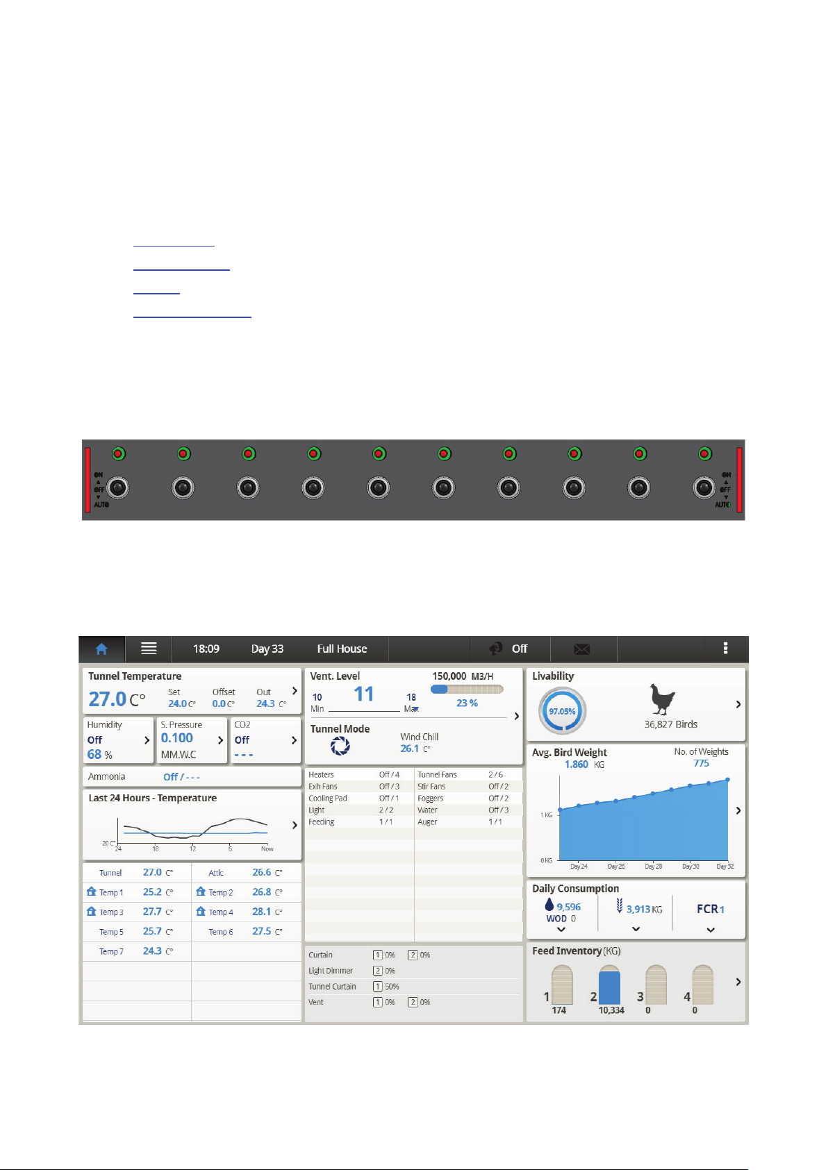
2.1 Main Screen
Figure 1 shows the Platinum Touch/Rotem One Touch Main Screen.
Figure 1: Platinum Touch/Rotem One Touch Main Screen
© Munters AB, 2018 9
Page 10
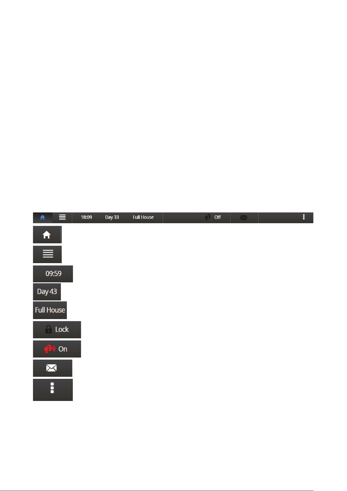
Click to return to the Main Screen
Click to open the Menu.
Displays the current time
Displays the growth day
Displays the house status (full house or brood mode) defined in the
Click this button to prevent any user from making changes to the parameters.
Click to turn off alarms. However,
register alarms until alarms are reset.
Click to read controller error messages
Click
Curve Status, Light Status, Natural Ventilation, Analog Output Status, Temperature
& Humidity Status, Feed Scale Status, Water Meters.
•
Temperature: Displays the average temperature, the set point the offset differential, and outdoor
temperature. Click on it to go to the Temperature Curve.
•
Ventilation level: This section displays the current minimum ventilation level and percentage of
air capacity being utilized. If minimum ventilation is being utilized, the screen displays the cycle
state and times. Click on it to go to Levels of Ventilation.
•
Livability: Current number of living birds and the corresponding percentage relative to the
original number. Click on it to go to Bird Inventory.
•
Current relative humidity, static pressure, and CO2 levels. Click on it to go to the Humidity
Treatment, Static Pressure, and CO2 Treatment screens.
•
Average bird weight graph: This graph summarizes the flock's weight over the growth cycle.
Click on it to go to Bird Weight History.
•
Temperature over the last 24 hours. Click on it to go to the History View.
•
Alarm messages. The Main Screen lists the latest alarms.
•
Sensors: This area displays the tunnel and attic target temperatures, the temperature readings for
each individual temperature sensor, and the wind speed.
•
Feed Inventory: Shows the current feed levels in the silos. Click to go to Feed Inventory.
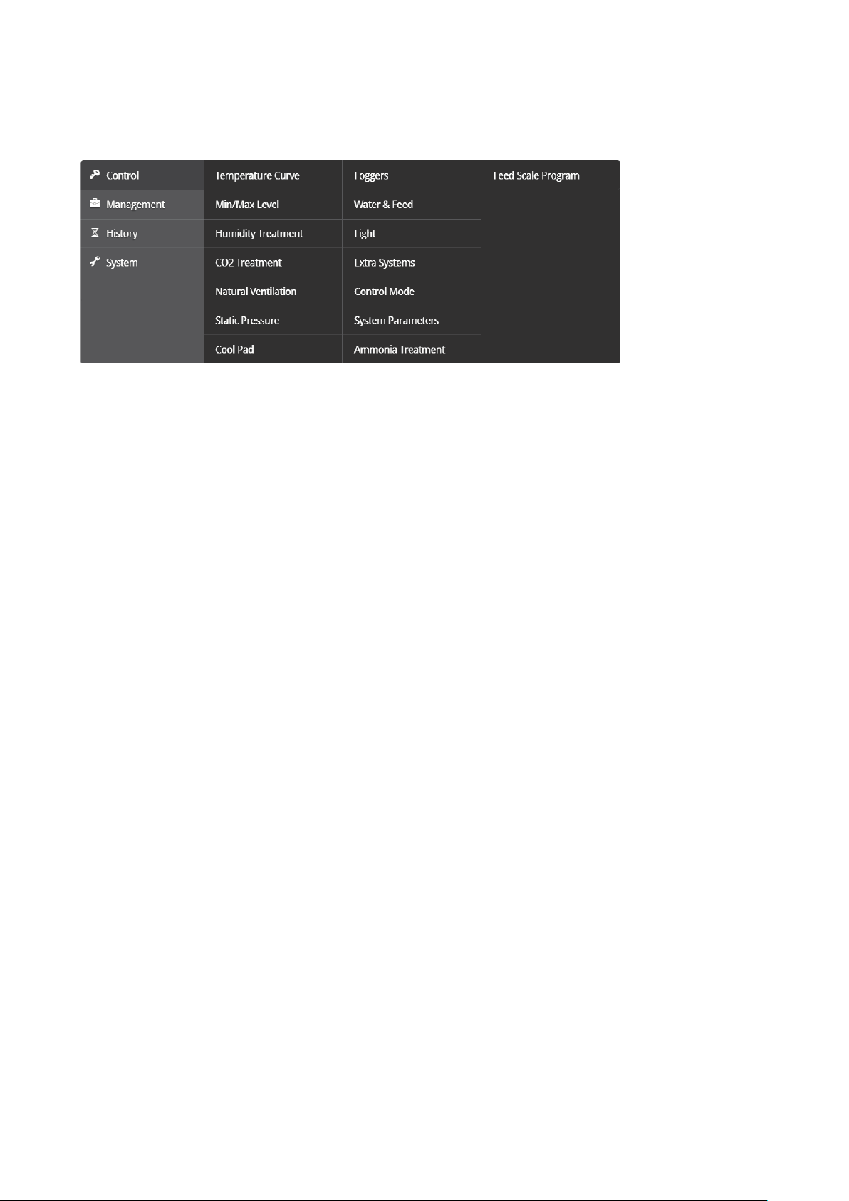
2.2 Menu Elements
Platinum Touch/Rotem One Touch continues to
one of these links to view screens summarizing information on this function:
2.3 Version
•
Go to System > Version to see the unit's software version.
© Munters AB, 2018 10
Page 11
2.4 Software Upgrade
You can upgrade certain software programs from the Web application.
•
Platinum Touch/Rotem One Touch software
•
Web application
•
Comm-Box software
NOTE You cannot upgrade product software! Upgrade your product software using the procedures
given in the product manuals.
NOTE Software upgrade can only be done locally!
1. Request the software upgrade from your dealer. You will be sent (via email, web transfer, etc.) a
UPD file.
2. Place the file on a disk on key/flash drive.
3. Place the disk on key/flash drive into the controller’s USB port (found on the Touch door interior).
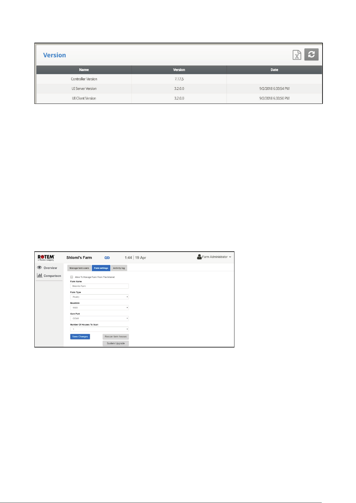
4. On the Touch screen, go to System > Software Update. The following screen appears.
Figure 2: Farm Settings
5. Click System Upgrade. The following screen appears:
© Munters AB, 2018 11
Page 12
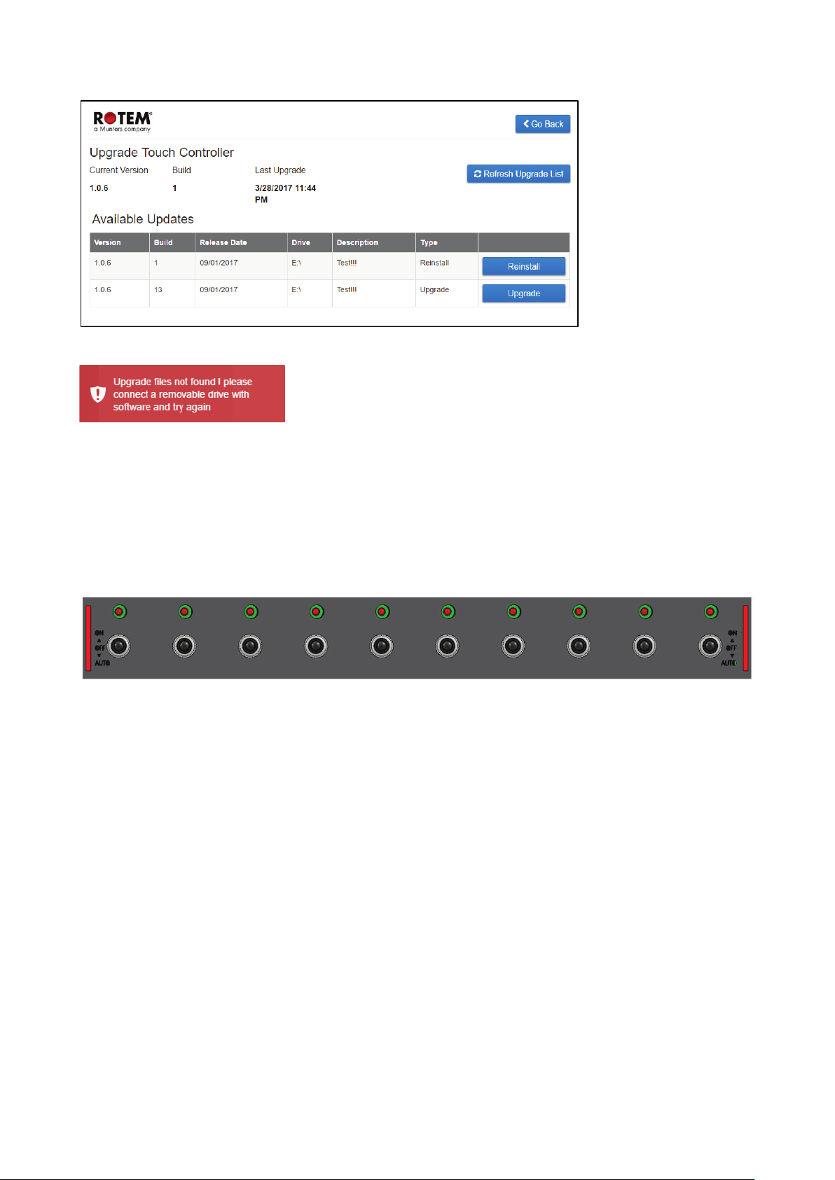
NOTE If you did not place the disk on key in the USB port, an error message appears:
6. The screen lists the UPD files on the disk. Select the required filed and click Upgrade (or Downgrade if
you are installing a previous version).
2.5 Rotem One LEDs
Rotem One Touch features LEDs on each relay panel. These LEDs turn red on all relay cards when there is
any active alarm (even one); they are white when there are no alarms. Refer to the main screen to view
the alarms.
2.6 Selecting the Mode
Platinum Touch/Rotem One Touch runs in four modes: Broiler, Layer, Breeders, and Pigs.
To select the mode:
1. Open the door. Locate the keyboard.
2. Disconnect the power cable from the power source.
3. On the keyboard, press the Delete button and reapply power. The Cold Start screen appears.
4. Select Yes. Choose Controller Type appears.
5. Select the required mode.
6. Press Enter.
NOTE The manual is based on the Broiler Mode. Functions that are unique to Layers and Breeders
and described in separate appendixes. Except for a few functions dealing with scales, Pig
Mode supports the vast majority of functions seen in Broiler Mode. Pig Mode has some
different terminology (for example herd instead of flocks).
•
Appendix C: Layers Mode
•
Appendix D: Breeders
© Munters AB, 2018 12
Page 13
3 Control Menu
The following sections detail:
•
Temperature Curve
•
Minimum/Maximum Level
•
Introduction to Humidity, Ammonia, and CO2 Treatment
•
Humidity Treatment
•
CO2 Treatment
•
Natural Ventilation
•
Static Pressure
•
Cool Pad
•
Foggers
•
Water & Feed Control
•
Light
•
Extra Systems
•
Control Mode
•
System Parameters
•
Ammonia Treatment
•
Feed Scale Program
•
Light Dimmers
NOTE If an RLED 2.0 is connected to the Platinum Touch/Rotem One Touch, the menu includes “Light
Dimmers”. Refer to Light Dimmers, page 56.
© Munters AB, 2018 13
Page 14
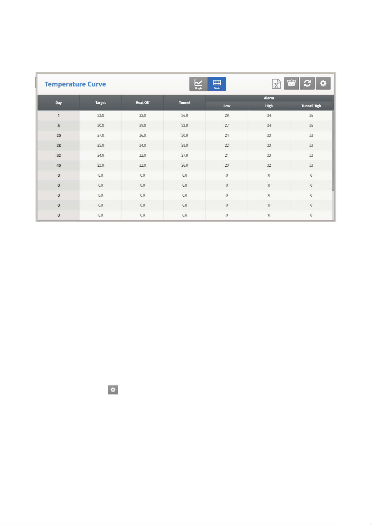
3.1 Temperature Curve
This screen sets the temperature targets according to the bird age.
1. In System > Sensors > Analog, designate the required number of sensors as temperature sensors.
When using more than one sensor, Platinum Touch/Rotem One Touch begins treatments based on
the average.
2. In System > Temperature Definition, assign specific sensors to devices. If a zone does not have
an assigned sensors, calculations are based on the current average temperature.
3. In Control > Temperature Curve, define the required target temperature curve.
o
Set up to 20 lines, 999 growth days. When a curve is not required (for example when
growing layers), enter temperatures in the first line only.
o
Define:
•
Day: Set the growth day. You can program negative growth days up to -2 for prewarming.
•
Target: Set the desired temperature.
•
Heat Off: Set the temperature at which heating ceases.
•
Low and High Alarm: Set temperature alarm limits.
•
Tunnel: Set the temperature at which tunnel ventilation begins.
4. In Management > Alarm Settings, set the alarms.
5. If required, click and set the parameters.
•
Temperature Curve Help | Set Definitions
•
Cycle Heaters Help | Set Definitions
•
Radiant Heaters Help | Set Definitions
•
Variable Heater Help | Set Definitions
© Munters AB, 2018 14
Page 15
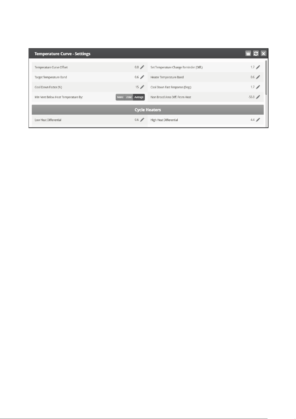
3.1.1 T
•
EMPERATURE CURVE HELP | SET DEFINITIONS
Define:
o
Temperature Curve Offset: Adjusts all temperature curves by this amount. You can use
this to temporarily adjust all temperatures up or down for special circumstances. The
curve appears in the Curve Status Hot Screen. Use the ENTER and Up or ENTER and
Down combinations to change the offset.
o
Set Temperature Change Reminder (Diff): Sets the change in set temperature that
triggers a reminder for you to set backup thermostats. Often producers forget to set
backup thermostats as their birds grow from baby chicks to market age, so the Platinum
Touch/Rotem One Touch reminds you. When you press Enter to acknowledge the
reminder, the Platinum Touch/Rotem One Touch logs it in the Table of Events.
o
Target Temperature Band: The size of the target temperature zone. This "Happy Zone”
is between Target Temperature and (Target Temperature + Band).
o
Heater Temperature Band: Heaters turn on at ‘Band’ degrees below Heat, and turn off
at the Heat Temperature.
NOTE Heaters operate at minimum level only; however, Radiant Heaters can operate at any
temperature or level below Tunnel.
o
Cool Down Factor (%): Minimum percentage correction towards target during each
increase ventilation level delay. If average temperature does not decrease by this
amount, the Platinum Touch/Rotem One Touch increases ventilation by one level.
o
Cool Down Fast Response (Deg.): Set a limit to the maximum degrees per minute of
cooling. If Average Temperature drops more than this in one minute, Platinum
Touch/Rotem One Touch decreases ventilation one level to avoid overshooting.
NOTE Avoid making this parameter too small or the normal temperature variation caused by timer
fans reduces the ventilation level.
o
Minimum Ventilation Below Heat Temp: Tells controller to go directly to minimum level
in some cases. Select from the following choices:
•
None: Operate by the normal level decrease time delay rule.
•
Zone: Go directly to minimum level if any active temperature sensor reaches heat
temperature.
•
Avg.: Go directly to minimum level if the average temperature reaches heat
temperature.
© Munters AB, 2018 15
Page 16
o
Non Brood Area Diff. From Heat: Set differential temperature for non-brood
heaters. You normally use this to set temperatures in unoccupied areas (poultry modes
only).
NOTE When set at -99° F the heaters are effectively disabled, since it will probably never go to 99º F
below the heater temperature. Putting this parameter at 0º sets the non-brood areas to the
heater temperature.
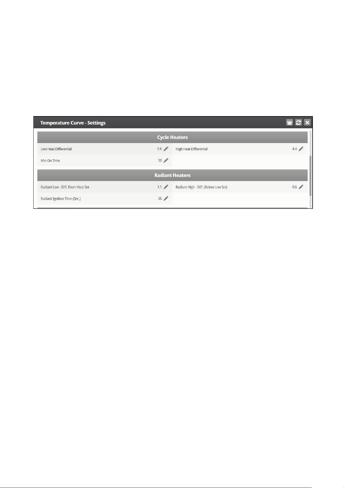
3.1.2 C
YCLE HEATERS HELP | SET DEFINITIONS
Heat Cycle means providing heat in conjunction with the ventilation system during minimum ventilation
cycles, using heaters and fans connected to relays. When enabled, heaters operate during the fans’
cycle off time (as defined in the Cycle Heaters Help | Set Definitions parameters). How does it work?
Between the Heat Temperature and the differential temperature, heaters do not operate. When the
temperature goes below the Heat Off temperature minus the Low Heat Differential:
•
Heaters begin to operate when the exhaust or tunnel fans are off. Heaters operate for the
Minimum On Time.
•
If the temperature continues to drop, heaters operate for longer periods of time, up to the
Maximum On Time (defined in Levels of Ventilation).
•
Platinum Touch/Rotem One Touch automatically generates a curve.
In this example:
•
Temperature Curve Heat Off is 78°.
•
Low Heat Differential is 1°.
•
High Heat Differential is 8°.
•
Minimum On time is 30 seconds.
•
Cycle Off time is 270 seconds.
© Munters AB, 2018 16
Page 17

1. Define the required number of heater and exhaust and/or tunnel relays (Relay Layout, page 94).
2. In Control > Control Mode, set the Heater Cycle to Yes.
3. In Control > Temperature Curve > Help, scroll to Cycle Heater.
4. Define:
o
Low Heat Differential: The differential below the Heat Off temperature, at which heating
begins and runs for the minimum amount of time.
o
High Heat Differential: The differential below the Heat Off temperature, at which heating
runs for the maximum amount of time.
o
Minimum ON Time: Minimum heating time when the exhaust or tunnel fans are off.
3.1.3 R
To configure the radiant heaters:
ADIANT HEATERS HELP | SET DEFINITIONS
1. In System > Relay Layout define at least one relay as a radiant heater.
2. Define:
o
Radiant Low – Differential from Heat Set: Set degree of difference from Heat for LOW
Radiant Heaters to begin working. This differential can be positive or negative. (default:
2.0)
o
Radiant High – Differential (Below Low Set): Set number of degrees below Radiant
Low Heaters for HIGH Radiant Heaters to begin working (default: 1.0). To ensure
proper heater ignition, Radiant High Heaters remain on for the Radiant Ignition Time
along with the Radiant Low Heaters.
© Munters AB, 2018 17
Page 18
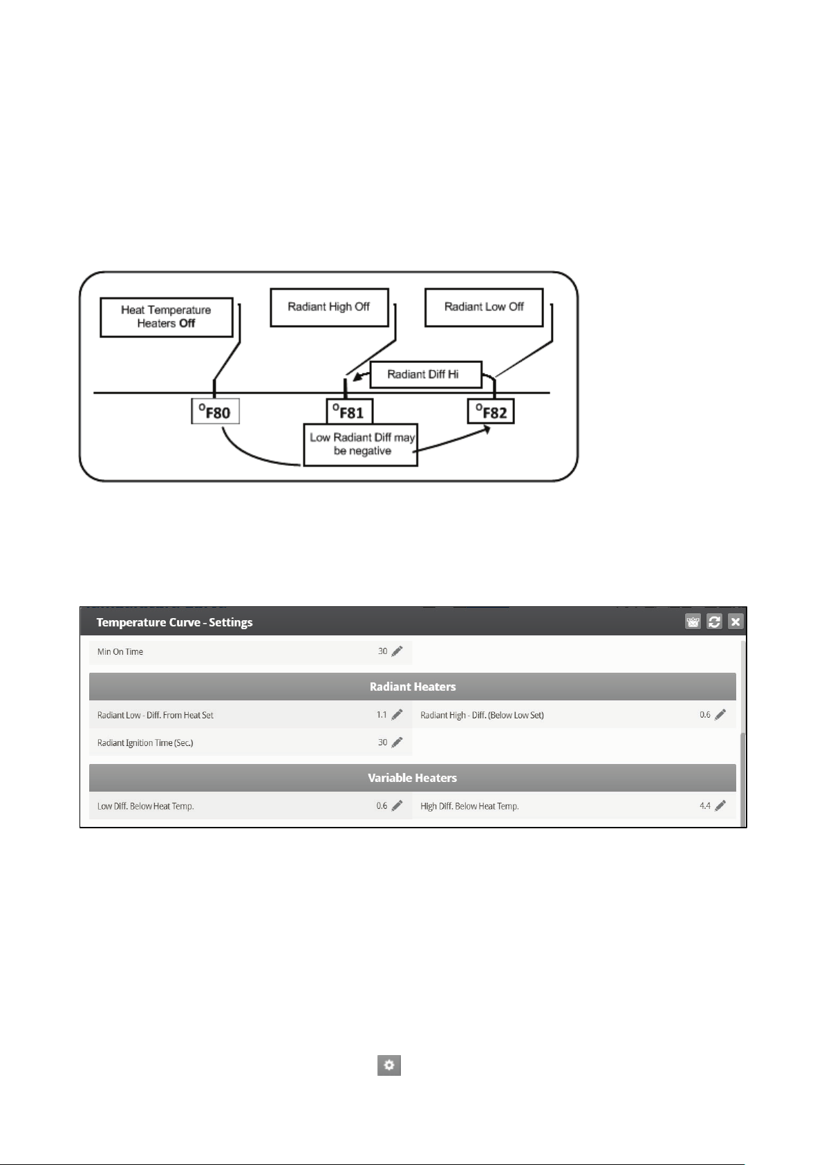
o
Radiant Ignition Time (sec): Set number of seconds to power radiant ignition (default:
30).
NOTE The Heater Temperature Band applies to radiant heaters as well. For example, if the Heat
Temperature is 80º F and the Heater Temperature Band is 1º F, then heaters turn on at 79º F
and off at 80º F. If the Radiant Low Differential is at 2.0º F, than radiant heaters turn off at
82º F, and on 1º F below that at 81º F. However, a Radiant High Heater turns on regardless
of its temperature setting for the Radiant Ignition Time whenever the corresponding Radiant
Low Heater turns on. This feature ensures proper flame ignition.
Figure 3: Radiant Heater Differentials
3.1.4 V
The Platinum Touch/Rotem One Touch enables configuring up to eight variable heaters. The output of the
heaters changes as the temperature increases or decreases.
ARIABLE HEATER HELP | SET DEFINITIONS
Install at least one analog output card.
To configure the variable heaters:
1. In System > Analog Output configure:
a. up to eight analog outputs as variable heaters.
b. the minimum and maximum voltage output for each heater.
2. In Control > Control Mode, define the Analog Heat Mode:
o
Linear Heat
o
Proportional Heat
o
Linear Valve
3. In Control > Temperature Curve, click and scroll to Variable Heater.
© Munters AB, 2018 18
Page 19
4. Define the parameters as required.
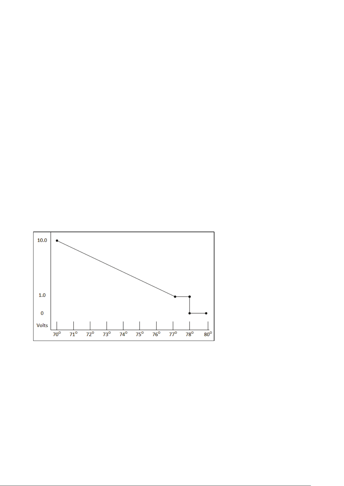
3.1.4.1 Linear Heat
When Linear Mode is enabled:
•
Between the Heat Temperature and the Target temperature, heaters do not operate (meaning,
the output voltage is 0).
•
Between the Heat Temperature and the Low Difference Below Heat, heaters operate at the
minimum voltage output.
•
If the temperature continues to drop, the voltage output increases until it reaches the maximum
voltage output at the High Difference below Heat.
In this example:
•
Target Temperature is 80°
•
Temperature Curve Heat Off is 78°.
•
Low Heat Differential is 1°.
•
High Heat Differential is 8°.
o
If the temperature is between 77° to 78°, the output voltage is the minimum voltage
defined in Installation > Analog Output (1 volt in this example).
o
If the temperature continues to drop, the output voltage increases until it reaches the
maximum voltage defined in Installation > Analog Output. Output increases or
decreases to keep the temperature within the Target Temperature and Heat Off band.
Figure 4: Linear Heat Curve
•
Define:
o
Low Difference Below Heat: Temperature difference between the Heat Off parameter
at which the variable heater begins to function.
o
High Difference Below Heat: Temperature at which the heater begins to operate at
maximum output.
3.1.4.2 Proportional Heat
Proportional Heat works in manner similar to Linear Mode. The difference is that Proportional Heat
features a delay time.
© Munters AB, 2018 19
Page 20
•
When the temperature falls below the user-defined point, the heaters begin operating at their
minimum output.
•
After the response time passes, Platinum Touch/Rotem One Touch checks the temperature. If it
is still below the defined point, Platinum Touch/Rotem One Touch increases the voltage by a
certain amount (this amount of the increase cannot be changed).
•
After the response time passes, the process is repeated until heaters operate at their maximum
output.
•
Define the parameters.
o
Difference Above Heat to Stop Heater: Differential from target temperature at which
the heater runs at minimal input.
o
High Difference Below Heat: High Difference Below Heat: Temperature at which the
heater begins to operate at maximum output.
o
Response Time (seconds): Amount of time before the controller begins to change the
ventilation.
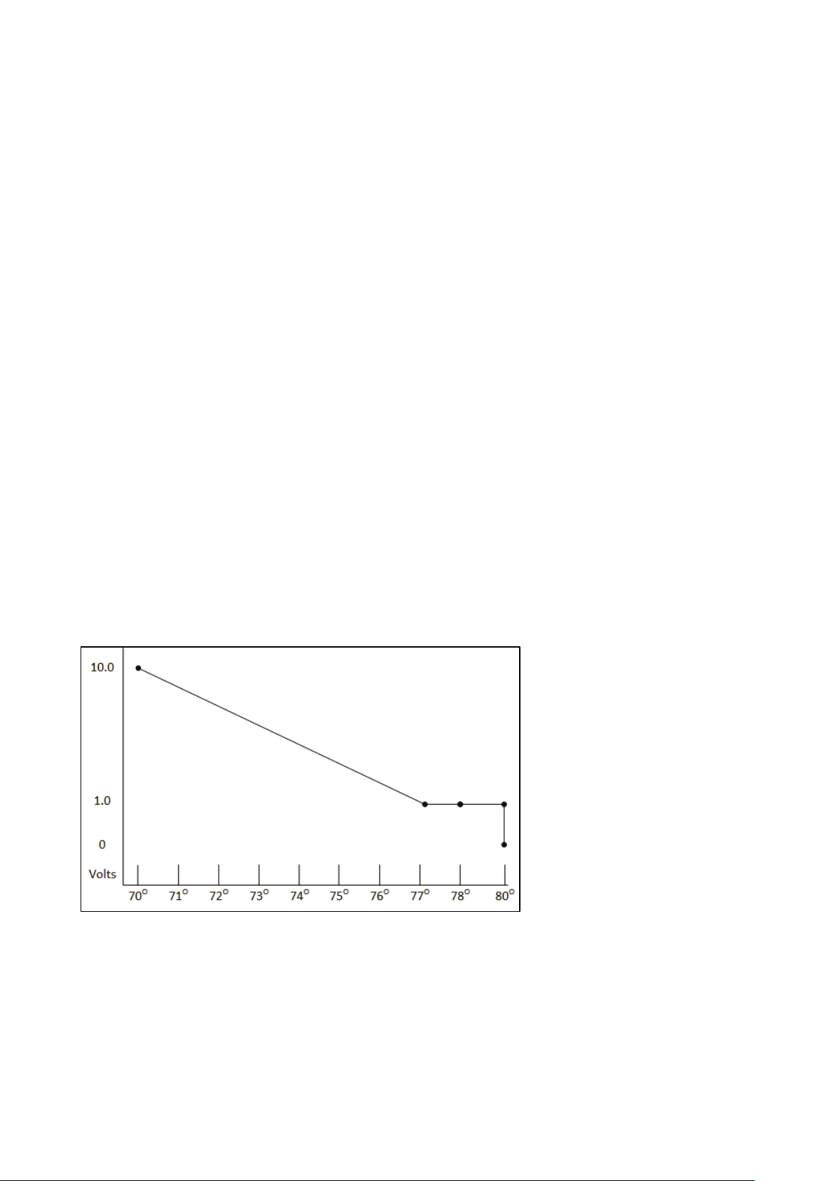
3.1.4.3 Linear Valve
Linear Valve enables defining that variable heater input voltage is always equal to or above the minimum
input defined in Installation > Analog Sensors.
When the Analog Heat Mode is defined as having Linear Valve control, there is always a minimal
voltage input. Therefore, if the minimum voltage is 1 volts:
•
The voltage range is from 1 to 10 volts
o
this corresponds to 10% at 1V and 100% at 10V
o
interpolation inside the band
•
There is 0% voltage when the target temperature is reached.
Figure 5: Linear Valve Curve
•
Define:
o
Difference Above Heat to Stop Heater: Differential from target temperature at which
the heater runs at minimal input
o
High Difference Below Heat: High Difference Below Heat: Temperature at which the
heater begins to operate at maximum output.
© Munters AB, 2018 20
Page 21

3.2 Minimum/Maximum Level
IMPORTANT: Before setting Min/Max level, go through and set up the Device Settings,
especially the ventilation levels.
Once you have entered the ventilation levels, use the Min/Max to select the range of levels to apply to
your situation. Typically, Platinum Touch/Rotem One Touch increases the minimum ventilation level as
litter conditions deteriorate and the birds require greater amounts of fresh air. You can also restrict the
maximum level to prevent excess airflow on young birds.
Go to Control > Control Mode to select the minimum ventilation method:
•
By Day and By Days with Curve
•
By Time
•
Soft Min / Max
•
By Weight
3.2.1 BY D
•
By Day operates according to each day's minimum and maximum values, the following defined
day is reached.
•
By Days with Curve generates an incremental increase/decrease between the defined days.
•
Define:
AY AND BY DAYS WITH CURVE
o
Day: Set growth day
o
Minimum Level: Set minimum ventilation level for controller
o
Maximum Level: Set maximum ventilation level for controller
© Munters AB, 2018 21
Page 22
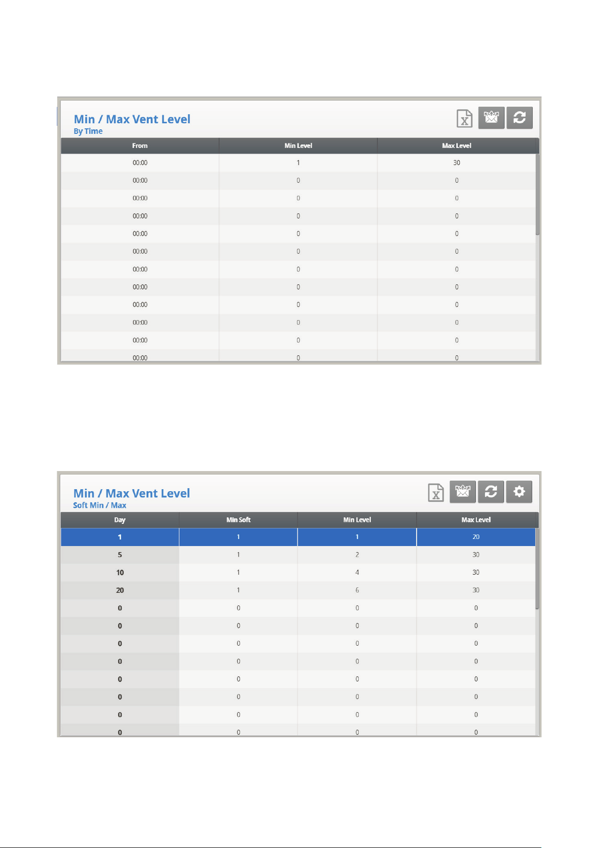
3.2.2 BY T
•
Define:
IME
o
From: Set time of day (hh:mm) in 24 hour format.
o
Minimum Level: Set minimum ventilation level for controller.
o
Maximum Level: Set maximum ventilation level for controller.
3.2.3 S
1. Define:
OFT MIN / MAX
o
Day: Set the growth day.
© Munters AB, 2018 22
Page 23
o
Min Soft: Set the minimum ventilation level for when temperature drops below heat
temperature.
o
Minimum Level: Set the minimum ventilation level for when temperature is above heat
temperature.
o
Maximum Level: Set the maximum ventilation level for controller.
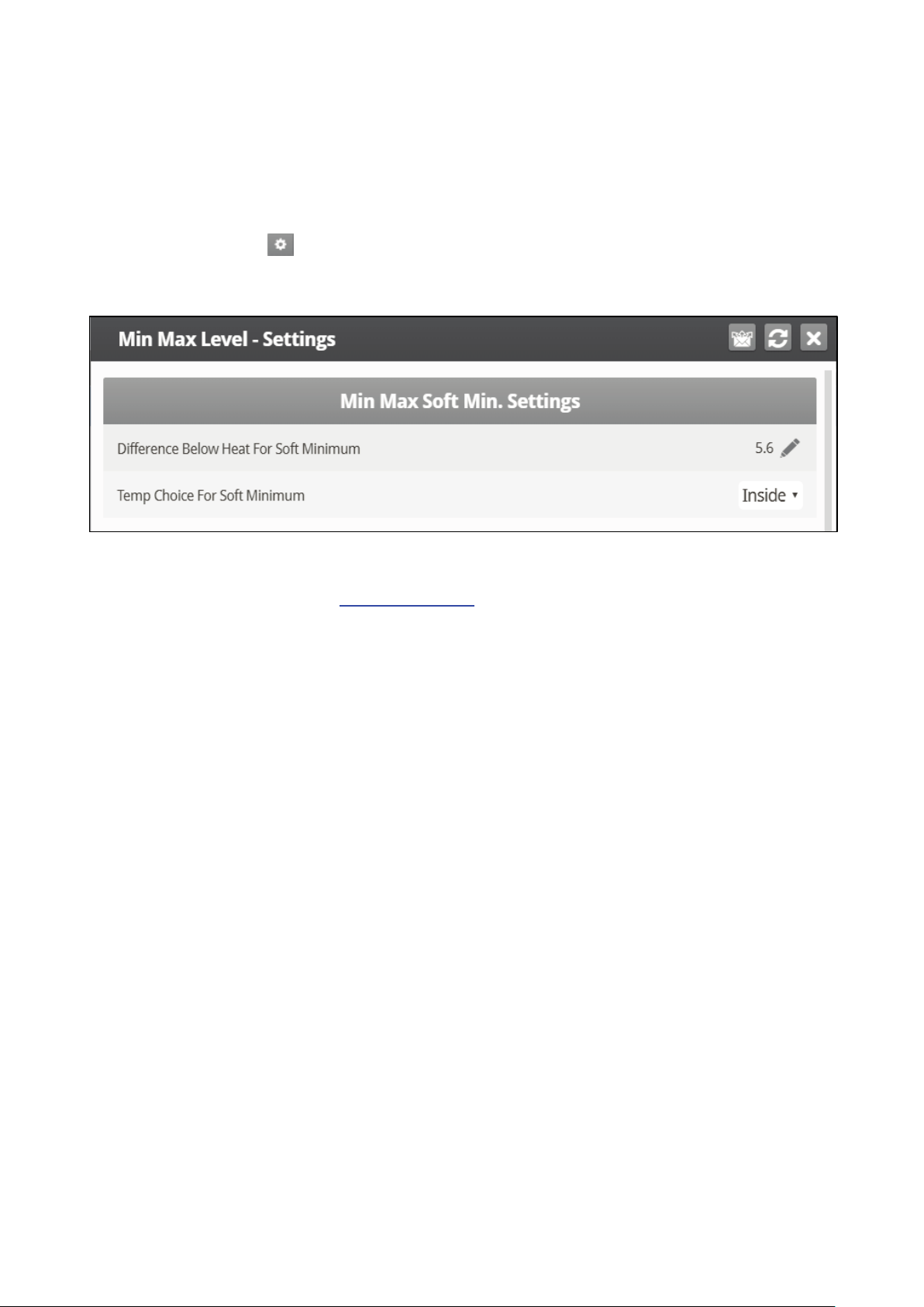
2. If required, click and set the parameters.
3.2.3.1 Soft Min/Max Level Help | Set Definitions
•
Define:
o
Difference Below Heat for Soft Minimum: Set the degree of difference from the heat
temperature (set in Temperature Curve) to switch the minimum level from Min. to Soft
Min.
o
Temp Choice for Soft Minimum: Select inside/outside/attic temperature to control
Minimum Level changes. The minimum level adjusts towards the Soft Min as this
temperature falls. Above the heat temperature, the minimum level is at the Min setting.
As temperature rises, INSIDE and ATTIC stay at lowest ventilation level reached until average
temperature gets to the heat setting, and then changes instantly. With the OUTSIDE selection, the
minimum ventilation level increases gradually as temperature rises to the heat setting. This means inside
and attic soft min vent choices to latch to the lowest level reached as long as the temperature remains
below the heat setting.
3.2.4 BY W
EIGHT
The By Weight option enables controlling the minimum air flow depending on the number of birds, their
weight and the current outside temperature. When using the Weight option, Platinum Touch/Rotem One
Touch takes several parameters and calculates the air speed, level of ventilation and cycle time needed to
supply the required volume. As opposed to the other ventilation methods, the Weight option is dynamic,
with the ventilation changing according to the current parameters (quantity of air required, weight of birds
and number of birds, outside air temperature). In addition, Ventilation By Weight sends out an alarm if
the current ventilation is below the minimum required level.
To set up the Weight Option:
1. In System > Setup, enable Minimum Ventilation.
2. In System > Temp Definition, define at least one temperature sensor as Outside.
3. In System > Fan Air Capacity, define the air capacity / hour.
4. In System > Scale Setting> General, select the curve.
5. In System > Bird Curve, define the growth days and weights as required.
© Munters AB, 2018 23
Page 24
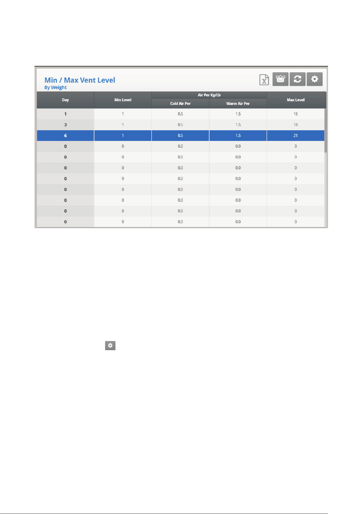
6. In Control > Control Mode > Min. Max Level Control menu, select By Weight.
7. In Control > Min/Max Level, set the parameters as required.
•
Day: Set growth day.
•
Minimum Level: Set the minimum level of ventilation.
•
Air Per Kg/Lb: Volume of air per kilogram/pound per hour per bird.
o
Cold Air Per: Volume of air supplied when the outside temperature goes down to the
Cold Temperature parameter (see the following section).
o
Warm Air per: Volume of air supplied when the outside temperature reaches Warm
Temp. – Diff Below Heat (see the following section).
NOTE As the level rises between days (for example between day 6 and day 10 in the screen above),
the air volume rises proportionally each day, once a day. For example, on Day 7, the Cold Air
per Kg/Lb rises to 0.65; on Day 8, 0.8 and so on.
•
Maximum Level: Set the maximum level of ventilation.
8. If required, click and set the parameters.
9. In Management > Inventory, type the number of birds.
© Munters AB, 2018 24
Page 25
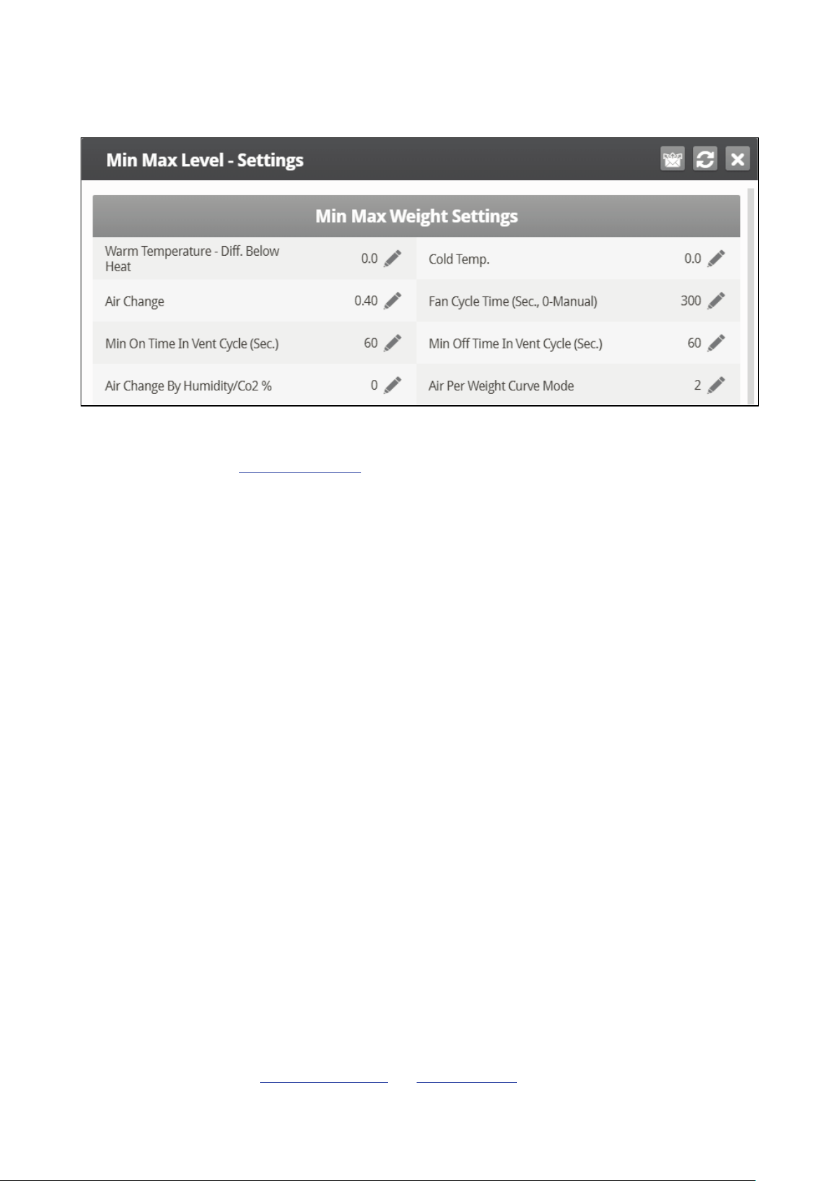
3.2.4.1 Minimum/Maximum By Weight Help | Set Definitions
•
Define:
o
Warm Temperature – Difference Below Heat: Differential below the heat temperature
(refer to Temperature Curve) that defines outside temperature as Warm in the Soft
Min/Max table. For example, if the Heat Temperature is 78° F, Warm Temp. – Diff
Below Heat is 2.0, than the outside temperature is defined as warm at 76° F.
o
Cold Temperature: Outside temperature (or below) at which Air per Kg/Lb. (Cold)
capacity is reached.
NOTE When the outside temperature is between the Warm and Cold Temperature, the flow rate is
calculated at a proportional rate.
o
Air Change: As the temperature rises from the Cold Temperature parameter to the Heat
Temperature (or drops from the Heat Temperature to the Cold Temperature parameter),
the minimal air volume rises/falls proportionally. Air Change defines the minimal change
in air temperature that must takes place to cause a change in the air supply.
o
Fan Cycle Time: The total amount of time that the fans operate while operating under
Minimum Ventilation. During this time, the fans supply the required volume of air at the
minimum ventilation level required. Platinum Touch/Rotem One Touch adjusts the
minimum ON time and OFF time as needed. If the fans cannot supply the required
volume at a particular level of ventilation, Platinum Touch/Rotem One Touch
automatically adjusts the minimum ventilation level.
o
Minimum ON Time in Vent Cycle: The minimum amount of time that the fans operate
during a ventilation cycle. Platinum Touch/Rotem One Touch adjusts the actual fan time
as needed.
o
Minimum OFF Time in Vent Cycle: The minimum amount of time that the fans do not
operate during a ventilation cycle. Platinum Touch/Rotem One Touch adjusts the actual
fan time as needed.
As the temperature rises, the actual Minimum OFF Time decreases until it reaches the minimum time;
only then does the Minimum On Time begin to rise.
NOTE If the temperature goes above the Band Temperature, Power Ventilation begins and times are
adjusted accordingly.
o
Air Change By Humidity/CO2%: As the humidity/CO2 levels rise above the levels
specified in Humidity Treatment and CO2 Treatment, the minimal air volume rises
© Munters AB, 2018 25
Page 26
proportionally. Air Change By Humidity/CO2% defines the minimal change in these
levels that must take place to cause an increase in the air supply.
o
Air Per Weight Curve Mode: By default, Air per Kilo/Lb. has two data points: cold
temperature and warm. If desired, the user can add an additional intermediate data
point which is between the two default points. This point determines the quantity of air to
be distributed when the temperature reaches the midpoint between the cold and warm
temperatures.
3.3 Introduction to Humidity, Ammonia, and CO2 Treatment
Platinum Touch/Rotem One Touch provides various options to controlling the humidity, CO2, and
ammonia levels.
•
None: No treatment is provided.
•
Level: Ventilation levels increase for a designated amount of time.
•
Tunnel or exhaust fan: A designated fan turns on for a designated amount of time. The amount of
air blown into the house is greater than that provided by an increase in ventilation level.
•
Increase in air / weight: The total amount of air that fans need to provide increases by a user
defined amount. Fan stay on until CO2, humidity, or humidity levels fall to their defined levels.
This option is only available when using Minimum Ventilation by Weight.
•
Humidity treatment by heat: In cold air situations, heaters can be turned on to lower the relative
humidity.
If there is a contradiction between CO2, humidity, and ammonia treatments:
• Ammonia treatment has priority over CO2 treatment.
• C02 treatment has priority over humidity treatment.
• Increase in air / weight has priority over other treatments.
• Humidity treatment by heat takes priority over increasing the ventilation.
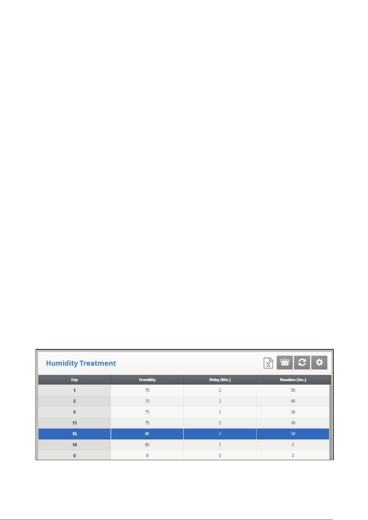
3.4 Humidity Treatment
Humidity treatment forces an increase in ventilation level when the humidity is too high. It holds the
increase for ‘Duration Seconds’, and checks back after ‘Interval Minutes’ for another increase. After the
duration, the ventilation level comes back down automatically.
© Munters AB, 2018 26
Page 27
1. In System > Sensors > Analog, designate one or two sensors as indoor humidity sensors (outdoor
sensor is for information only). When using more than one sensor, Platinum Touch/Rotem One
Touch begins treatments based on the average.
2. In Control > Humidity Treatment define:
o
Day: Set the growth day. You can set multiple programs for same day (maximum number
of programs: 20)
o
Humidity: Set the humidity level at which to begin treatment.
o
Delay (Min): Set the amount of time the controller pauses before ventilating.
o
Duration (Sec): Set the number of seconds the controller maintains the increased level of
ventilation
3. Set the Humidity Sensor Alarm.
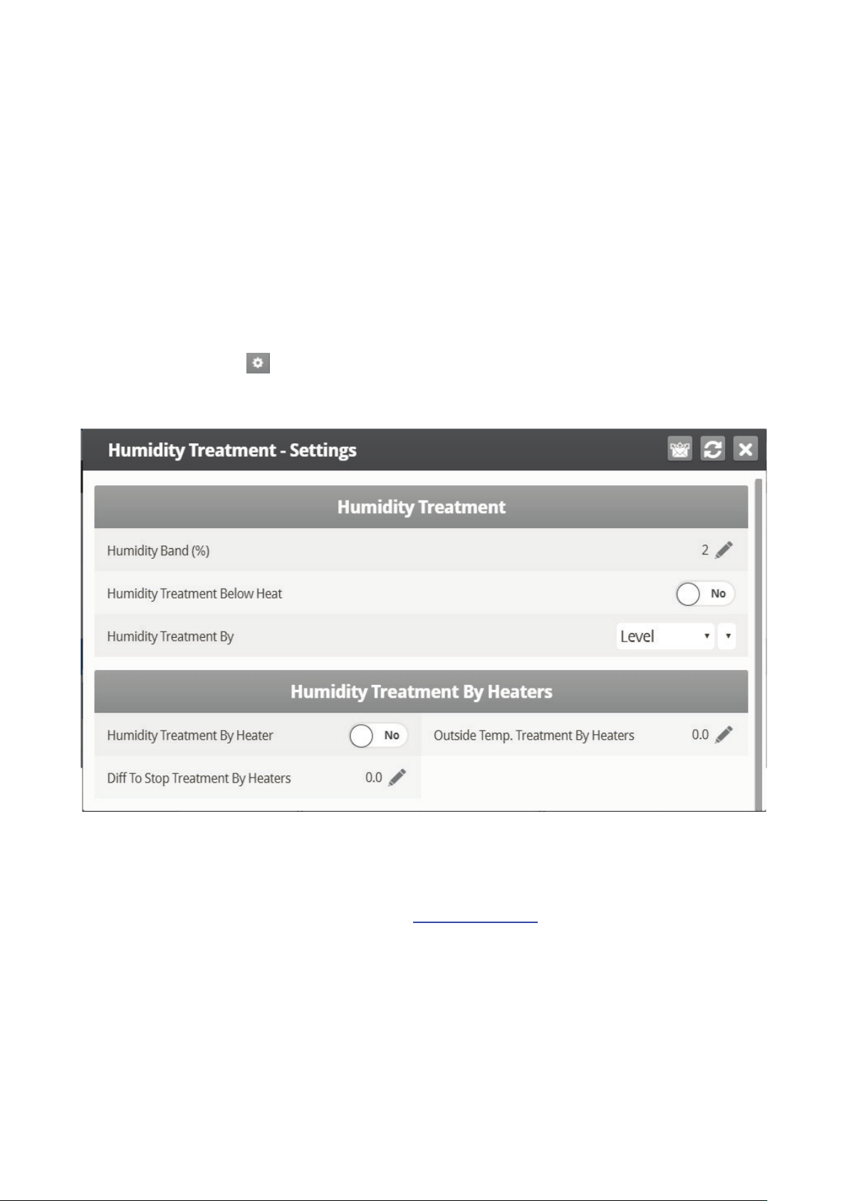
4. If required, click and set the parameters.
3.4.1 H
•
UMIDITY TREATMENT HELP | SET DEFINITIONS
Define:
o
Humidity Band (%): Set the differential band for Humidity Treatment. For example, if the
humidity target is 75% and the band is 2%, treatment begins at 77%.
o
Humidity Treatment below Heat: Select YES or NO for allowing Humidity Treatment
when heaters are operating (set in Temperature Curve).
o
Humidity Treatment By: This parameter designates the method used when humidity or
CO2 treatment begins. Normally, this parameter is relevant only when minimum
ventilation is running. When a treatment is required, select the method to be employed:
•
None: Disables the treatment.
•
Level: Increases the ventilation level when a treatment is required.
NOTE When employing Ventilation by Weight, the controller increases the cycle time or the level,
depending on the particular settings.
© Munters AB, 2018 27
Page 28

o
Humidity Treatment by Heaters: This parameter enables using the heaters to lower the
relative humidity. If enabled, define:
•
Outside Temp Treat by Heaters: A differential from the target temperature; when the
outside temperature reaches this point, heaters turn on and remain on for the duration
time.
•
Diff to Stop Treatment by Heaters: A differential from the target temperature; when the
inside temperature reaches this point, heaters turns off and remain off for at least the
duration time. This number can be positive or negative.
Humidity Treatment by Heater requires designating at least one thermometer as an outside
thermometer (refer to Temperature Definition, page 99).
NOTE If the heaters are operating because of the interior temperature, Humidity Treatment by Heater
is disabled.
NOTE Broiler and Breeder Modes support Humidity Treatment by Heaters.
3.5 CO2 Treatment
CO2 treatment forces an increase in ventilation level when the CO2 level is too high. It holds the increase
for ‘Delay Seconds’, and checks back after ‘Interval Minutes’ for another increase. After the duration, the
ventilation level may come back down automatically. If during treatment, the CO2 level drops below the
Stop Value parameter, the ventilation level automatically returns to that level used before CO2 treatment
was initiated.
1. In System > Sensors > Analog, designate one sensor as a CO2 sensor.
2. In Control > CO2 Treatment define:
o
Day: Growth day. You can set multiple programs for same day (maximum number of
programs: 20)
o
Start Value: CO2 value at which to begin treatment
o
Stop Value: CO2 value at which to end treatment
o
Delay: Number of seconds the controller pauses before ventilating
© Munters AB, 2018 28
Page 29

o
Duration: Number of seconds the controller maintains the increased level of ventilation
3. Set the CO2 Sensor Alarm.
4. If required, click and set the parameters.
3.5.1 CO2 TREATMENT HELP | SET DEFINITIONS
•
Define:
o
CO2 Treatment below Heat: Select YES or NO to enable CO2 treatment when heaters
are operating (set in Temperature Curve).
o
CO2 Treatment By: This parameter designates the method used when humidity or CO2
treatment begins. Normally, this parameter is relevant only when minimum ventilation is
running. When a treatment is required, select one the method to be employed:
•
None: Disables the treatment.
•
Level: Increases the ventilation level when a treatment is required.
NOTE When employing Ventilation by Weight, the controller increases the cycle time or the level,
depending on the particular settings.
o
CO2 Treatment by Heaters:
CO2 Treatment by Heater: This parameter enables running the heaters in situations where the
CO2 level is high. Typically this can happen in cold temperatures when CO2 is produced by
the heaters. By increasing the heat in the house, ventilation can then be increased. If
enabled, define:
•
Outside Temp Treat by Heaters: A differential from the target temperature; when the
outside temperature reaches this point, heaters turn on and remain on for the duration
time.
•
Diff to Stop Treatment by Heaters: A differential from the target temperature; when the
inside temperature reaches this point, heaters turns off and remain off for at least the
duration time. This number can be positive or negative.
CO2 Treatment by Heater requires designating at least one thermometer as an outside
thermometer (refer to Temperature Definition, page 99).
© Munters AB, 2018 29
Page 30

NOTE If the heaters are operating because of the interior temperature only, CO2 Treatment by
Heater is disabled.
3.6 Natural Ventilation
Natural Ventilation enables supplying the house's air requirements using the wind. Using the Natural
Ventilation depends on a variety of environmental and scheduling factors. While in this mode, curtains
open and close based on the target temperature.
Setting up the Natural Ventilation is a multiphase process.
•
How Does Natural Ventilation Work
•
Preliminary Steps
•
Defining Natural Conditions
•
Defining Natural Operation
•
Natural Programming Help | Set Definitions
•
What Happens When the Controller Transitions?
3.6.1 H
OW DOES NATURAL VENTILATION WORK
For Platinum Touch/Rotem One Touch to switch to Natural Ventilation:
•
Natural Ventilation works only during the defined growth days and daily schedule.
•
The temperature inside the chicken house must be within the inside temperature band.
•
The temperature outside the chicken house must be within the outside temperature band.
•
If the temperature is below either of the above two parameters, ventilation switches to Minimum.
•
If the temperature is above either of the above two parameters, ventilation switches to Tunnel
(there is an option to remain in natural ventilation; refer to Minimum Wind Speed for Tunnel
Temp).
•
The wind speed must be within the wind speed band.
•
The wind direction must be within the user-defined area.
NOTE Including the wind speed and direction in Natural Ventilation calculations is optional and
requires in the installation and configuration of additional equipment.
•
If the weather conditions meet the above requirements, curtains open to a calculated position
based on the difference temperature and minimum and maximum percentage. If more air is
required, the curtains adjust themselves automatically using a calculation based on the minimum
and maximum curtain position. The larger the difference between the minimum and maximum
openings, the larger the step.
•
Any change in the curtain position takes place after the Delay Time.
3.6.2 P
RELIMINARY STEPS
Install a wind speed and rain detector (optional).
Install a wind direction sensor (optional).
1. In System > Setup > Natural Ventilation, select:
o
Level: This option instructs the controller to run Natural Ventilation using the levels shown
in Device Settings > Vent and Curtain Levels. If you choose this option, no further setup is
required.
© Munters AB, 2018 30
Page 31

o
Program: This option uses the parameters listed below to determine curtain opening.
2. If you installed a wind speed and rain detector, in System > Digital Sensors, define the sensors
accordingly.
3. If you installed a wind direction sensor:
a. In System > Sensors > Analog Sensor, define the sensor accordingly.
If required, calibrate the wind direction sensor (refer to Wind Direction Calibration).
b. In System > Air Inlets Setup, define the each curtain's direction. When making Natural
Program calculations, the controller only takes into consideration winds coming from a
certain direction. Any wind whose source is outside of this area is disregarded.
The number entered here defines the area (the number entered ±90°) (Figure 3: Wind Direction
Sensor Definition).
o
If you enter 90, the range is from 0 - 180°.
o
If you enter 45, the range is from 315 - 135°.
Figure 6: Wind Direction Sensor Definition
NOTE In both cases, winds A or B would be factored into the calculations whereas winds C or D
would not. Only calibrate the sensors if you have reason to believe that they are producing
inaccurate results.
The number entered here defines the area on both sides of the sensor! Figure 6 illustrates a chicken
house with four wind sensors. Sensor 1's Wind Direction parameter is defined as 45° or 90° total.
Winds that come within this area (A) are used for Natural Programing. The controller disregards winds
outside of this area (B & C).
4. If required, in System > Temperature Definition designate a temperature sensor as an outside
sensor.
© Munters AB, 2018 31
Page 32

3.6.3 D
EFINING NATURAL CONDITIONS
Natural Conditions define when the controller switches to Natural Ventilation.
•
Define:
o
From/To Day: Sets start and end day for the Natural Program
o
From/To Time: Sets starting and finishing time for the Natural Program
o
Low Outside Temperature Diff from Target: The band below the Current Target
Temperature in which Natural Programming operates (outside temperature). Range: -20
to +20° C.
o
High Outside Temperature Diff from Target: The band above the Current Target
Temperature in which Natural Programming operates (outside temperature). Range: -20
to +20° C.
o
Minimum Wind Speed to Enter: Sets the wind speed required to enter Natural
Program.
o
Maximum Wind Speed to Exit: Sets wind speed required to exit Natural Program.
o
Minimum Wind Speed for Tunnel Temperature: When the unit is in Natural Mode, if
the temperature rises above the Tunnel Temperature, Platinum Touch/Rotem One Touch
switches to Tunnel mode unless the wind speed is above the speed set here.
NOTE The above three parameters require installing and configuring a wind speed sensor.
© Munters AB, 2018 32
Page 33

3.6.4 D
EFINING NATURAL OPERATION
Natural Operation defines how the controller functions in Natural Ventilation.
•
Define:
o
Low Temperature Diff from Target: The band below the Current Target Temperature in
which Natural Programming operates (inside temperature).
o
High Temperature Diff from Target: The band above the Current Target Temperature in
which Natural Programming operates (inside temperature)
o
Curtain Step Size: Set the curtain to open by this amount at each level (%).
o
Curtain Delay Between Steps (sec.): To prevent excess switching between steps, set a
delay time.
o
Minimum Curtain Position: Set the minimum curtain open position.
o
Maximum Curtain Position: Set the maximum curtain open position.
o
Wind and Rain Effect: Enables Platinum Touch/Rotem One Touch to consider additional
parameters (found in the Help) when calculating the maximal curtain opening.
© Munters AB, 2018 33
Page 34

3.6.5 N
ATURAL PROGRAMMING HELP | SET DEFINITIONS
1. Define the Natural Entrance Conditions:
o
Enable Natural In Tunnel: Enables using Natural Ventilation definitions when in Tunnel
mode.
o
Wind Gust Delay Time: Set the delay time for recalculating curtain movement if the wind
speed changes.
o
Disable Stir Fan Above W. Speed: Above this wind speed, Stir Fans cease to operate
when in Natural Programming.
o
Min. Time in Any Vent Mode (min): Minimal amount of time that the controller waits
before changing into Natural Programming (from Minimum Ventilation or Tunnel Mode).
Similarly, the controller remains in Natural Ventilation for at least this time.
o
Use Tunnel As Natural Curtain: Use tunnel curtains when in Natural
Programming. When disabled, curtains remain closed.
2. Define the Natural Mode Operation:
o
Low Wind Speed: Below this speed, curtains open completely. This number must be
higher than the Minimum Wind Speed to Enter.
o
High Wind Speed: Above this wind speed, the controller lowers the curtain maximum
opening percentage to this point.
NOTE Between these levels, the controller opens the curtain based on a curve.
o
Low Wind Speed With Rain: If there is a rain detector, curtains open completely when
there is rain.
o
High Wind Speed With Rain: If there is a rain detector, curtains close completely when
there is rain.
NOTE Between these levels, the controller opens the curtain based on a curve.
© Munters AB, 2018 34
Page 35

3.6.6 W
HAT HAPPENS WHEN THE CONTROLLER TRANSITIONS?
When the controller transitions to or from Natural Ventilation the following changes take place
•
Side/Power > Natural: Fans stop, curtains open to the calculated position and finally the side
inlets close.
•
Tunnel > Natural: Fans stop, curtains open to the calculated position. When the curtains reach
their maximum opening position, the tunnel closes (unless the tunnel mode operates to open in
natural Mode.
•
Natural > Side/Power: The controller automatically calculate most suitable Power Ventilation
Level, depending on the Target Temperature and current Inside Temperature.
•
Natural > Tunnel: The controllers automatically calculates the most suitable ventilation level
depending on the Target Temperature and current Inside Temperature (minimum or tunnel).
3.7 Static Pressure
Set target parameters for attic, minimum, and tunnel ventilation.
In System > Setup, enable a static pressure unit.
Refer to Static Pressure Calibration and Static Pressure.
•
Static Pressure Method
•
Disabling the Static Pressure Sensor
•
Static Pressure Help | Set Definitions
•
Multi Stage Tunnel Curtains
3.7.1 S
TATIC PRESSURE METHOD
•
Attic Static Pressure
•
Minimum Ventilation Static Pressure
•
Tunnel Ventilation Static Pressure
3.7.1.1 Attic Static Pressure
•
Define:
o
Target Static Pressure: Set the required static pressure when in attic mode.
o
Static Pressure Band: Set the required band for attic ventilation mode.
© Munters AB, 2018 35
Page 36

3.7.1.2 Minimum Ventilation Static Pressure
•
Define:
o
Static Pressure at Low Temperature: Set desired static pressure for low outside
temperature conditions. Be sure that there is proper airflow at this setting.
o
Static Pressure at High Temperature: Set desired static pressure for high temperature
conditions. Normally this pressure is lower to obtain a larger air inlet opening.
NOTE Controller interpolates between the LOW and HIGH Temperature. If Static Pressure exists, it is
controlled by the outside temperature sensor, otherwise by the average temperature.
o
Low Static Pressure Alarm: Set alarm for low static pressure. If you disable it by setting
zero, the Platinum Touch/Rotem One Touch warns you and enters a record in the Table
of Events.
o
High Static Pressure Alarm: Set alarm for high static pressure.
o
Static Pressure Band: Set desired band for the target pressure.
3.7.1.3 Tunnel Ventilation Static Pressure
•
Define:
o
Target Static Pressure: Set the required static pressure for Tunnel Ventilation Mode.
o
Low Static Pressure Alarm: Set the alarm for low static pressure.
o
High Static Pressure Alarm: Set the alarm for high static pressure.
o
Static Pressure Band: Set the required band for pressure in tunnel ventilation mode.
© Munters AB, 2018 36
Page 37

3.7.2 D
ISABLING THE STATIC PRESSURE SENSOR
To disable the static pressure sensor:
1. Go to System > Setup.
2. Set the Static Pressure Unit to None.
The main screen stops:
•
displaying the pressure
•
displaying High Pressure and Pressure Sensor Failure alarms
NOTE If either of these alarms were active before disabling the sensor, the main screen continues to
display the alarms. Reset the alarms one time to cease the display.
3.7.3 S
TATIC PRESSURE HELP | SET DEFINITIONS
•
Define:
o
Wind Gust Delay Time (sec): Set length of time in seconds before starting Static
Pressure control after an unexpected change in air pressure.
o
Static Pressure During Tunnel: Select YES or NO for using Static Pressure control when
in Tunnel mode.
o
Transitional Tunnel: Select YES or NO for using tunnel curtains when static pressure is
high and vents are already at 100%.
o
MinVent Using: Select VENT or TUNNEL to control static pressure when in minimum
ventilation.
o
Incoming Air Low Temperature (Deg): Define low temperature for static pressure
control.
o
Incoming Air High Temperature (Deg): Define high temperature for static pressure
control.
o
Emergency Static Pressure Delay (sec): Set length of time in seconds before initiating
an emergency opening when pressure exceeds high alarm setting.
o
Curtain Position in Emergency Static Pressure % (0 – Disable): Set the required
curtain position (in percentage) when an emergency pressure event occurs.
o
Low Static Pressure Alarm Minimum Level (MinVent): Below this level, the controller
ignores low static pressure alarms when in minimum ventilation.
o
Low Static Pressure Alarm Minimum Level Low S.P. Alarm Min. Level (Tun.): Below
this level, the controller ignores low static pressure alarms while in tunnel mode.
© Munters AB, 2018 37
Page 38

o
Time to Produce Static Pressure (sec): Enter the length of time to reach target pressure
when minimum ventilation fan cycle is on.
o
Attic Advance Opening Time (sec): Define the amount of time for the attic inlets to open
before minimum vent cycling fans turn on.
3.7.4 M
ULTI STAGE TUNNEL CURTAINS
When in static pressure mode and employing multiple tunnel curtains, Platinum Touch/Rotem One Touch
can open the curtains in sequence. Opening the tunnel curtains commences when the target static
pressure is reached and the controller signals to the tunnel machine to operate the curtains. Platinum
Touch/Rotem One Touch opens the first tunnel curtain (as defined in the relays) to the user defined
level. If additional ventilation is required, the second tunnel curtain opens. This process continues for
each defined curtain.
As pressure falls, the process is reversed; curtains close in progression starting with the last curtain.
To set up Multi Stage Tunnel Curtains:
1. In System > Relay Layout define more than one relay as tunnel curtain (open and close).
2. In System > Levels of Ventilation > Vent & Curtain Levels, define the opening levels for each curtain.
3. In Static Pressure > Tunnel Ventilation, define the target pressure.
3.8 Cool Pad
This menu sets the cool pad operating conditions.
NOTE Cool Pads only operate when the controller is in tunnel mode. For example, if the cool pad is
set to run at Level 8 and the tunnel mode begins at level 10, the cool pad remains inoperative.
1. In System > Relay Layout, define relays as Cool Pad.
2. Go to Control > Cool Pad.
3. Define:
•
Day: Set the growth day in this field.
•
Start Time: The cool pad begins operating at this time.
•
End Time: The cool pad ceases to operate at this time.
o
It is possible to set multiple start and stop times for a single day.
o
In the screen above, growth day jumps from day 1 to day 5, the cool pad continues to
work according to day 1 settings from growth day 1 through growth day 5.
•
Tunnel Diff: Set the band above the target temperature so that the cool pad begins to operate at
this temperature.
© Munters AB, 2018 38
Page 39

Cool Pad #
Assigned Sensor
Diff Between Cool Pads Stage
Actual ON temperature
Average
0.0
Average
2.0
Temp Sensor 2
0.0
Temp Sensor 2
2.0
•
To Humidity: Set the maximum allowed humidity before stopping the cool pad.
•
On Sec: Set the maximum on time for each cycle of cool pad operation.
•
Off Sec: Set the minimum off time for each cycle of cool pad operation.
4. If required, click and set the parameters.
3.8.1 C
•
OOL PAD HELP | SET DEFINITIONS
Cool Pad
Define
o
Temperature Band: Define the on/off delay relative to temperature.
o
Humidity Band (%): Define the on/off delay relative to humidity.
o
Diff Between Cool Pads Stage: Platinum Touch/Rotem One Touch supports four cooling
pad stages. The controller activates the first stage when the temperature reaches the
Tunnel Temperature (Control > Temperature Curve) plus the Tunnel Differentiation (set in
the Cool Pad screen). Each additional stage begins when the temperature reaches the
Tunnel Temperature plus the Tunnel Differentiation plus this differentiation.
For example, if:
•
Tunnel Temperature = 80°
•
Tunnel Diff = 2
•
Diff between Cool Pads Stage = 3
Stage 1 starts at 82°, Stage 2 at 85°, Stage 3 at 88°, and Stage 4 at 91°.
Example: Cool Pad ON temperature = 80°, Diff set to 2º F:
1
2
3
4
o
Cool Pad Minimum Level: In systems having more than one pump, this parameter
80°
82°
80°
82°
enables keeping a cool pad inoperative until the associated tunnel curtain turns on.
Define the minimum level for each cool pad.
© Munters AB, 2018 39
Page 40

NOTE When the Difference Between Cool Pads Stage is enabled, the cool pads operate according to
both conditions.
Cool Pad Flush
o
Flush Cool Pad At: Enter the time to flush cool pads.
o
Cool Pad Flush Duration (minute): Enter the process duration time.
3.9 Foggers
This menu sets the Foggers operating conditions. Foggers differ from the Cool Pad:
•
Foggers and Cool Pad have a different temperature reference point. The Fogger Temperature
Differentials are relative to the target temperature; the Cool Pad is relative to the tunnel entry
temperature.
•
Foggers operate even when the controller is not in tunnel mode.
1. In System > Relays, define relays as Fogger.
2. In Control > Foggers, define:
•
Day: Set the growth day.
•
Start Time & End Time: Time of day you want foggers to start and stop.
o
It is possible to set multiple start and stop times for single day.
•
Target Diff: Set difference from the tunnel temperature to trigger foggers.
•
To Humidity: Set maximum humidity allowed before stopping foggers.
•
On Sec: Set the maximum on time for each cycle of fogger operation.
•
Off Sec: Set the minimum off time for each cycle of fogger operation.
3. If required, click and parameters as required.
3.9.1 F
OGGERS HELP | SET DEFINITIONS
© Munters AB, 2018 40
Page 41

•
Define:
o
Temperature Band: Define the on/off delay relative to temperature.
o
Humidity Band (%): Define the on/off delay relative to humidity.
o
Minimum Level to Enable Operation: Select the minimum ventilation level to operate
the foggers.
o
Maximum Level to Enable Operation: Set the maximum ventilation level for fogger
operation.
o
Enable Rotation: Enable this function to use a different fogger relay each cycle. This
function enables dispersing the droplets at a higher pressure, to wet the animal.
NOTE Munters recommends keeping this function set at the default setting (No).
o
Difference between Foggers Stage: Platinum Touch/Rotem One Touch supports four
fogging stages. The controller activates the first stage when the temperature reaches the
Target Temperature (Control > Temperature Curve) plus the foggers differential. Each
additional stage begins when the temperature reaches the Target Temperature plus the
fogger differentiation.
3.10 Water & Feed Control
This menu sets the operating conditions for water and feed devices.
There are control two methods:
•
Control via Time
•
Control via Quantity
3.10.1 C
1. In System > Relay Layout, define relays as Water, Feed, or Auger.
2. Go to Control > Water & Feed > Set.
ONTROL VIA TIME
3. Set Quantity to No.
4. Go to Control > Water & Feed.
© Munters AB, 2018 41
Page 42

5. Define:
•
•
•
Day: Set growth day. You can define days as negative days.
Time: Set event times for water, feeder, or auger.
Water/Feeder/Auger: Turn on the required devices that will run at the set times.
6. Set the Water Overflow Alarms and Water Shortage Alarms.
NOTE You can implement mealtime, clean up meals and other options similarly as shown earlier in the
light programs.
3.10.2 C
ONTROL VIA QUANTITY
1. In System > Relay Layout, define relays as Water, Feed, or Auger.
2. In System > Scale Layout, map each silo to a channel.
3. Go to Control > Water & Feed > Set.
4. Go to Control > Water & Feed.
© Munters AB, 2018 42
Page 43

5. Define:
•
•
•
•
•
Day: Set growth day. You can define days as negative days. Growth days stay at the defined
parameters until the next defined day.
From Time/To Time: Set the time period during which water and feeding lines can operate.
Water: Select a check mark to mark water lines to turn on, dot the ones to turn off.
Feeder: Check mark feed lines to turn on, dot the ones to turn off.
Feed: Enter the quantity of feed provided from the silos during the From/To time.
o
You can provide feed from multiple silos, enabling specific feed mixes.
o
Distribution continues until the To Time or until the defined quantity is reached, whichever
comes first.
o
If a relay is not defined as an auger the Feed numbers still appear. However any quantity
entered is meaningless.
Water runs continually between the From/To times. Only feed is distributed in cycles.
NOTE This function only works when relays are defined as augers and each silo is mapped to an
auger. Defining a digital sensor as a feed count does not enable Control by Quantity.
NOTE If both Control via Quantity and a digital feed counter are enabled, Control via Quantity takes
priority.
© Munters AB, 2018 43
Page 44

3.10.3 WATER AND FEED HELP | SET DEFINITIONS
These parameters define the feed and water delivery schedule through the week.
NOTE The Water and Feed parameters work in conjunction with the Lighting parameters.
•
Feed Day Cycle:
o
Daily: Same schedule for every day of the week.
o
2 – 6 Days: Select a cycle that lasts the number of days chosen and then repeats itself.
For example, 2 Days means that the cycle lasts two days and then repeats itself.
o
Week: Select which days in the week that feed and water are delivered.
•
Quantity: Enable this feature to enable Control by Quantity.
NOTE If you choose Daily, the Scale function is always enabled. If you choose 2- 6 Days or Week,
the Scale function is
CAUTION
If you want to provide feed every day, select Daily. Selecting Week and marking each day
disabled
on non-feeding days.
causes problems with this function.
If you select the 2 – 6 Day schedule or the Week schedule, configure:
o
Week/Days Cycle (2 – 6 Days): Select which days in the cycle that feed and water is
delivered.
o
Water on No Feed Days: Select up to two time periods when water is delivered on non-
feed days.
NOTE On feed days, water is delivered when feed is delivered.
© Munters AB, 2018 44
Page 45

3.11 Light
This menu sets the lights operating conditions. The controller has a capacity for up to four channels of
On/Off Lights and up to 10 channels of Dimmer Lights. In addition, this menu enables using a light
sensor.
1. Do one or both:
•
In System > Analog Output, define up to 10 outputs as light dimmers.
•
In System > , Relays define up to 10 outputs as light.
2. In Control > Water & Feed > Help, define Feed by Cycle.
3. In Control > Light, select Light Feed. The Light parameters screen appears. These parameters
configure the Light functions on feed days.
o
If the Feed by Cycle is set to 2- 6 Days, select Light No Feed. The Light parameters screen
appears. These parameters configure the Light functions on non-feed days.
4. Define:
•
Day: Set Growth Day
In the example, the brood lights (channel 1) and bright center lights (channel 2) turn on from day 1,
while the grow end lights (channel 3) are off. The example shows two channels of light dimmer,
Channel 1 at 100% and Channel 2 at 0% (for baby chicks in the brood zone).
•
Time: Set event times for the lights.
o
On day 12, the center lights turn off, and the dimmer lights go to 45%. There are two
periods of darkness: from 01:00 to 03:00 in the morning, and 09:00 PM to midnight.
This program repeats until day 25.
o
From day 25 the on/off lights stay off, and the dimmer lights provide dim light during the
on periods, and go out fully for two periods of darkness. The dark periods total 6 hours,
being from midnight to 03:00 AM and from 08:00 PM (20:00) to 11:00 PM (23:00).
•
On/Off: Select the required light(s) to turn on.
•
Light Dimmer (%): Set intensity in percentage for light dimmer(s). Dimmer lights start to brighten
if the intensity increases, and complete dimming if the intensity decreases at the set time. That is,
they start dimming the ‘sunset time’ in advance of the set time (see Help | Set below).
© Munters AB, 2018 45
Page 46

5. If required, click and set the parameters.
3.11.1 L
•
IGHT HELP | SET DEFINITIONS
Define:
o
Sunrise Time (minutes): The amount of time required for the light intensity to rise from 0%
to the designated level.
o
Sunset Time (minutes): The amount of time required for the light intensity to decline from
the designated level to 0%.
o
Allow Spiking from Day: The day spiking begins.
o
Spike Cycle (minutes): The time length that the spike is at its maximum level. Reaching
the maximum level and returning to the preset level both take one minute. For example if
the spike duration is 10 minutes, the spike cycle is 8 minutes.
o
Spike Duration (minutes): The total amount of time of the spike cycle, including the rise
and fall times.
o
Spike Increase Amount (%): Set the increase in intensity for the spike in relation to the
current light intensity.
o
Signal Light Is: Only one light operates during feeding times. Select which light is lit or
choose “None”.
NOTE After the feeding period ends, all lights selected in the Light Parameters screen relight.
o
Signal Before Feed (seconds): Amount of time, before the feeding starts, that all other
lights go off.
o
Signal During Feed (seconds): Amount of time that the selected light remains on after
feeding ends.
NOTE The above two parameters are disabled on no feed days.
o
Light Sensor Active: The light sensor turns off all lights when sufficient outside lights
exists. If a light sensor is installed, enable this option to turn off the light during feeding
time when there is sufficient outside light. Refer to Light Sensor Calibration for details.
© Munters AB, 2018 46
Page 47

Figure 4: Lighting without Spiking
Figure 5: Lighting with Spiking
NOTE The initial reference time for the Spike Cycle is the end of Sunrise. The spike begins Spike
Duration minutes before the end of the Spike Cycle, and has one minute up and down ramps in
intensity. If Sunrise Duration is set to zero, no spiking occurs.
3.12 Extra Systems
This menu sets the parameters of other devices that are not listed in the controller.
1. In System > Relay Layout, define relays as Extra System.
2. Go to Control > Extra System.
3. Define:
•
Start Time: Time at which this Extra System starts.
•
End Time: Time at which this Extra System stops.
•
Temperature From: Temperature above which Extra System operates.
•
Temperature To: Temperature below which Extra System operates.
•
Humidity From: Humidity above which Extra System operates
•
Humidity To: Humidity below which Extra System operates.
•
On (Sec): On time for the Extra System. If set to 0, the extra system does not operate.
© Munters AB, 2018 47
Page 48

•
Off (Sec): Off time for Extra System after completion of on time. If you have values in both ON
and Off, the extra system cycles. If you have zero OFF time, and any ON time, the system simply
stays on as long as the other parameters are satisfied.
NOTE All parameters must be satisfied for an Extra System to operate. For example if the
temperature is below the From Temperature or the Humidity below the From Humidity, the
system is OFF. You can assign specific temperature sensors to an Extra System in Install | Temp
Definition. The Extra System uses the Inside Humidity, not the Outside Humidity. If there is no
humidity sensor, the Extra Systems ignore the humidity parameters.
3.13 Control Mode
Select house-operating modes, turn temperature curves on or off and select which type of min/max level
method to use.
•
Define:
o
House Mode: Select whether the house is in one of the brood set ups or in full house.
o
Empty House Mode: Select YES to disable alarms.
o
Temperature Curve: If you select OFF, temperature settings become fixed values until
midnight on the next setting in Temperature Curve.
o
Minimum Maximum Level Control: Set ventilation control method (By Days, By Days
Curve, By Time, By Soft Min, and Weight). Refer to Minimum/Maximum Level for more
details).
o
Heat Cycle: Enable cycle heaters. Refer to Cycle Heaters Help | Set Definitions, page
16.
o
Analog Heat Mode: Define the variable heating mode (Linear, Proportional, Linear
Valve). Refer to Variable Heater Help | Set Definitions, page 18.
© Munters AB, 2018 48
Page 49

3.14 System Parameters
System Parameters consolidates all of the HELP | SET menus into one scroll screen.
3.15 Ammonia Treatment
Ammonia treatment forces an increase in ventilation level when the ammonia level is too high. To prevent
fans changing their ventilation too often, treatment begins after a user-defined delay. The user also
defines the treatment duration.
After the duration, the ventilation level may come back down automatically. If during treatment, the
ammonia level drops below the Stop Value parameter, the ventilation level automatically returns to that
level used before ammonia treatment began.
This function requires an ammonia sensor.
1. In System > Analog Sensors (refer to Analog Sensors), designate one sensor as an ammonia
sensor.
2. If required, go to Service > Ammonia and calibrate the sensors (refer to Ammonia Calibration).
3. In Control > Ammonia Treatment set the parameters.
o
Day: Growth day. You can set multiple programs for same day (maximum number of
programs: 20)
o
Start Value: Ammonia value at which to begin treatment. Range: 0 to 100. Default: 2
NOTE Ammonia levels should not be higher than 30 ppm.
© Munters AB, 2018 49
Page 50

o
Stop Value: Ammonia value at which to end treatment. Range: 0 to 100. Default: 2
o
Delay (Sec): When the ammonia level reaches the start value, the controller delays
treatment for this amount of time. Default: 0
o
Duration (Sec): Number of seconds the controller maintains the increased level of
ventilation. Default: 0
4. Set the Ammonia Alarm (page 66).
3.15.1 AMMONIA TREATMENT HELP | SET DEFINITIONS
o
Ammonia Treatment below Heat: Select: Select YES or NO to enable Ammonia
Treatment when heaters are operating (set in Temperature Curve).
o
Ammonia Treatment By: This parameter designates the method used when ammonia
treatment begins. Normally, this parameter is relevant only when minimum ventilation is
running. When a treatment is required, select the method to be employed:
•
Level: Increases the ventilation level when a treatment is required.
NOTE When employing Ventilation by Weight, the controller increases the cycle time or the level,
depending on the particular settings.
•
Exhaust: Designate a specific exhaust fan (press a number key to select the fan).
•
Tunnel: Designate a specific tunnel fan (press a number key to select the fan).
•
None: Disables the treatment.
3.16 Feed Scale Program
NOTE Broiler Mode supports this function
Feed Scale enables mixing different types of feeds from (up to) four different feed bins. The user fills each
bin with the required feed type and sets the mixture rations and quantities in Platinum. The augers then
distribute the feed as defined.
This screen defines:
•
the total quantity of feed to be delivered to the birds
•
the auger feed mixture.
1. In System > Relay Layout (page 94), define relays as augers as required.
2. In Management > Bird Inventory (page 58), enter the number of birds.
3. Go to Control > Feed Scale Program.
© Munters AB, 2018 50
Page 51

4. Define:
o
Day: Define the days at which the feed per bird changes. Platinum Touch/Rotem One
o
Feed per Bird: Define the amount of feed per bird/pigs (kilograms) to be distributed.
o
Silo (%): If there is more than one silo supplying feed, enter the percentage of the feed
o
Total Feed: Displays the amount of feed required for that day. This amount is calculated
o
Today: These numbers display the actual amount of feed required for the current growth
Touch calculates a feed curve based on these days. You can define the days as negative
days.
Platinum calculates the total amount of feed to be distributed based on this parameter
and the Bird Inventory parameters.
package that each silo supplies. Note that by default, Silo 1 supplies 100% of the feed.
Any number entered in Silo 2, 3, or 4 is subtracted from Silo 1.
by multiplying the feed per bird by the number of birds in the bird inventory (taking into
account any birds culled, died, or moved).
day. In the example shown above, the growth day is Day 2. Platinum Touch/Rotem One
Touch calculates the curve from Day 1 to Day 5 and adjusts the numbers accordingly.
3.16.1 F
EED SCALE HELP | SET DEFINITIONS
•
Define:
© Munters AB, 2018 51
Page 52

o
Time: What time the hopper begins distributing feed to the birds or animals.
o
Maximum Portion Weight: Enter the feed scale container size.
o
Maximum Auger Time [minutes]: This parameter sets an alarm for the auger running
time. Enter the number of minutes that the auger can run, after which an alarm appears
on the Main Screen.
o
Not Empty Time [minutes]: This parameter sets an alarm for the feed container. The
container should distribute all of its feed to the feed lines. If feed remains in the container,
it could mean that there is a problem (for example, the valve doesn't open). Set the
amount of time that feed can remain in the container, after which an alarm appears on
the Main Screen.
o
Stop Differential 1/2/3/4 Weight: After each silo stops supplying feed to its auger
line, a certain amount of feed continues to flow. This differential compensates for this
excess and ensures that only the required amount gets to the feeding container. Enter the
approximate amount of feed that can be found in the augers. The number does not need
to be exact. In the following feed runs, Platinum will correct the amount entered.
o
Optimizer: This parameter sets the unit's sensitivity to signal noise (caused by a variety of
factors). The sensitivity plays a role as the controller stabilizes itself. Greater amounts of
noise require faster optimization. To view an indication of the controller's stability, go to
Scale Menu > Test (refer to page 61) and perform a test. If the number remains stable,
slower optimization is indicated. There are three settings; Default, Slower, Faster.
NOTE Munters recommends leaving this parameter at the default level.
o
Valve Close Time [seconds]: Set the delay in time, if any, that the valve emptying the
feed scale closes.
o
Feed Tare [A/D count]: This specification is used for certain tests performed by a
certified technician.
NOTE Munters recommends leaving this parameter unedited.
3.16.2 F
EED SCALE HOT SCREEN
This screen shows the status of different areas of the feeding apparatus. illustrates the system components.
© Munters AB, 2018 52
Page 53

•
Status: Shows the feed scale status: Idle, Emptying, or Filling.
•
Weight: Shows the feed scale container weight
•
Auger 1/2/3/4: Shows if the auger is running or off
•
Valve: Shows if the valve emptying the feed scale is open
•
Feed S. Active: This field shows which controller is managing the feed scale.
•
Feed S. Interlock: The Feed Scale Interlock is a digital sensor which detects which
damper is active.
•
Hopper: The hopper is a digital sensor which detects if the feed has reached the maximum
level in the feed bin. Define this sensor in System > Digital Sensor. This screen shows the
sensor's current status. If the feed reaches the maximum amount, an alarm is triggered..
•
Intermediate: The intermediate sensor is a digital sensor which detects if the feed has reached
the maximum level in the feed bin. Define this sensor in System > Digital Sensor. This screen
shows the sensor's current status.
•
Alarm: This parameter shows if there are active alarms. View the alarms on the Main Screen.
3.16.3 F
EED SCALE FUNCTIONALITY IN TWO HOUSES
Platinum Touch/Rotem One Touch enables sharing feed scale functionality between two houses. Two
load cells are connected to a single feed scale. Each Platinum Touch/Rotem One Touch Controller is
connected to one load cell.
When the system is running, one controller operates each set of augers, feed scale valve, hoppers, and
so on. A mechanical damper switches the feed supply from the scale to the corresponding hopper. Only
one feed process operates at a time; when one process is running the second is in standby.
•
Each hopper auger is managed by a separate feed sensor, installed in the last dish in the last
feed line in each house.
•
Both Platinum Touch/Rotem One Touch units are connected to a single feed scale container.
•
Contactors connected to the silo augers determine which house is active.
•
Each Platinum Touch/Rotem One Touch controller is connected to a separate hopper sensor,
which indicates when the hopper is filled.
•
Important: Each Platinum Touch/Rotem One Touch Controller transmits the Feed Scale State to
the second controller, via the Feed Scale Active Relay. This relay prevents a controller from
assuming control of the Feed Scale when the latter is active. Controller 1 will release control if:
o
The hopper sensor shows the hopper to be filled
o
The feed cycle is complete.
o
In addition, if an Auger Overtime alarm is generated, control is transferred to the other
Platinum.
•
Hot key (see Feed Scale Hot Screen)
© Munters AB, 2018 53
Page 54

Figure 7: Feed scale block diagram
© Munters AB, 2018 54
Page 55

To set up the Feed Scales:
Refer to the Installation manual on wiring the Controllers to the Feed Scale and Load Cells.
1. Go to System > Relay Layout.
2. Define a relay as Feed S. Active.
3. Go to System > Digital Sensor.
4. Define one sensor as Hopper Sensor and one sensor as Feed Scale Interlock.
© Munters AB, 2018 55
Page 56

HARDWARE CHECKLIST
Card
Box
Slot
Status
Chann.
Alarm 1
1 Relays
40
N.O. 1
1 1 OK
10
N.O. 2
1 2 OK
10
N.O. 3
1 3 OK
10
N.O. 4
1 4 OK
10
MDF
RLED
0 0 4
RLED 1
4 2 OK 2 RLED 2
4 3 OK 2 RLED 3
4 4 OK 2 RLED 4
4 5 OK 2 RLED 5
4 6 OK
2
3.17 Light Dimmers
Platinum Touch/Rotem One Touch supports configuring up to five RLED 2.0 Light Dimmers from the
Platinum Touch/Rotem One Touch screen. RLED 2.0 can be connected via a Platinum Touch/Rotem One
Touch communication card or via an analog output card. Each RLED 2.0 has two independent channels;
meaning five RLED 2.0 units fulfill the role of ten light channels.
NOTE Verify that UI Server Version/Client Version is 3.2.1 or higher. Update the software if required.
Install the units before attempting to configure the RLED 2.0s. Light Dimmers only appears
in the Installation Menu if RLED 2.0s are connected to the controller. Refer to the RLED 2.0
Installation Manual for details.
NOTE In the following screens, if an RLED 2.0 is connected to an analog output card, ~ appears next
to the light line (for example: ~Light 6).
1. On the keyboard: Go to Test > Hardware Checklist and verify that RLED appears and that the
status is OK.
RDT5
o
If the status is not OK, recheck the wiring.
o
If an RLED 2.0 is connected to an analog output card
The RLED 2.0 appears under Analog Output.
The channel address is 0.
2. Go to Installation > Light Dimmers.
© Munters AB, 2018 56
Page 57

3. On each line and channel (for example ADD-1, CH-A), map a lighting line to an RLED 2.0
channel. In this example, there are five RLED 2.0s, controlling all 10 lighting lines.
o
You can map the channels to the light lines in any order.
4. Go to Control > Light.
5. Define the parameters as described Light, page 45.
6. The main screen now displays the active and inactive light lines.
© Munters AB, 2018 57
Page 58

4 Management Menu
The following sections detail the Management Menu.
•
Bird Inventory
•
Feed Inventory
•
Growth Day and Flock
•
Alarm Settings
•
Alarm Reset
•
Fail Safe Settings
•
Password
•
Feeders & Drinkers
•
Nipple Flushing
•
Water on Demand
•
Current Sense
4.1 Bird Inventory
Maintain your inventory by entering data into the controller.
© Munters AB, 2018 58
Page 59

1. Enter the quantities under Birds Placed. There are separate rows for male and female. If you do
not wish to keep separate data, simply enter the data into one or the other.
2. When required, enter the quantity found dead, culled, or moved. Platinum Touch/Rotem One
Touch calculates the totals and subtotals.
3. You can correct an error, so long as you correct it on the same day before midnight. After
midnight, the information transfers to the Mortality Menu.
4.2 Feed Inventory
Maintain your feed inventory by entering data into the controller.
To enter feed inventory manually:
1. Enter the date.
2. Enter the feed quantity under the silo and press ENTER. The cumulative total appears in the Total
Feed row.
3. If required, click and set the parameters.
4. Set the Feed Alarms.
If you have installed load cells and connected silo scales to your Platinum Touch/Rotem One Touch, it
automatically maintains feed inventory, including delivery dates and feed consumption data. You can
monitor your fill system and maintain approximate feed inventory using the Digital Inputs. In this case,
you need to enter your own delivery dates.
This information transfers to the History > Water and Feed menus daily, or optionally as often as selected
(by the minute) in History View.
© Munters AB, 2018 59
Page 60

4.2.1 F
EED INVENTORY HELP | SET DEFINITIONS
•
Define:
o
Total Feed in Silo-1/ -2/ -3/ -4: Manually change or correct the amount of feed in the
silos.
o
Active Silo: Select the required silo for use. It is possible to select all of them.
4.3 Growth Day and Flock
This menu defines the number of growth days and flock number.
•
Define:
o
Flock Number: The controller automatically increments the group/flock number each
time you choose New Flock/Group. You can edit the flock number. Since this field
accepts six digits, some producers enter a flock number that is made of the day, month
and year the birds arrived.
o
Current Growth Day: Enter current growth day, if necessary. It is possible to enter
negative growth days up to -2. If you reset the growth day for a new flock using this tool,
your old history data does not clear. Use New Flock/Group function to clear out old
history in preparation for new birds.
o
New Flock: Use the new flock function on arrival of a new set of birds to set the growth
day back to 1, 0, -1, or -2, and to clear out old history data.
© Munters AB, 2018 60
Page 61

4.4 Alarm Settings
This menu defines the various alarm settings.
NOTE See Fail Safe Setting.
•
Define:
o
Global Alarm Delay (second): Alarms without a separate alarm delay, use this global
delay before signaling the alarm.
o
Alarm Reminder (minutes, 0-Disable): Amount of time before a reminder is sent if the
situation has not yet been corrected.
o
Sensor Low Temperature Range: Sets the minimum reading a sensor can have to be
considered a valid sensor reading. Sensor readings below this point are rejected. This
generates a sensor out of range alarm. This does not apply to the special Circuit Breaker
Sensor or Outside Temperature Sensor.
o
Sensor High Temperature Range: Sets the maximum reading a sensor may have to be
considered a valid sensor reading. Sensor readings above this point are rejected. This
generates a sensor out of range alarm. This does not apply to the special Circuit Breaker
Sensor or Outside Temperature Sensor.
o
Sensor Alarm-Differential from Low Alarm: Individual sensor (or zone) alarm if any
active sensor reads this much or more below the Control > Temperature Curve >Low
Alarm Temperature.
o
Sensor Alarm- Differential from High Alarm: Individual active growth area sensors
alarm if they read this much or more above the Control > Temperature Curve >Low Alarm
Temperature.
Sensor Alarm
Alarms
o
Alarm Test at Time (hh:mm): Schedule the alarm test time.
o
Day of Alarm Test: Choose Daily or a particular day of the week for the scheduled
alarm.
© Munters AB, 2018 61
Page 62

o
Alarm Test Duration (seconds): Enter the alarm test duration.
Auger Overtime Alarm
o
Auger Overtime Delay (minute): Set the maximum auger run time for your cross fill
system. If you have a monitor connected to the digital inputs programmed as Feeder-1
Overtime or Feeder-2 Overtime the Platinum Touch/Rotem One Touch sends an alarm
after this delay.
o
Feeder Off During Overtime: Choose whether to shut the feed systems off after a feeder
overtime alarm. Options:
•
No: All augers and feeders remain on.
•
YES: Al augers and feeders shut down.
NOTE If you choose
All
or
Related
, the feed system turns off and does not resume until you select
Reset Alarm in the Management Menu.
Feeder Overtime Alarm
o
Feeder Overtime Delay: Set the maximum feeder run time for your cross fill system. If
you have a monitor connected to the digital inputs programmed as Feeder-1 Overtime or
Feeder-2 Overtime the controller sends an alarm after this delay.
o
Feeder Off During Overtime: Choose whether to shut the feed systems off after a feeder
overtime alarm. Options:
•
No: All augers and feeders remain on
•
All: Al augers and feeders shut down.
•
Related: Only the specific auger from which the alarm originated and it feeders shut
down.
NOTE This alarm functions in the Broiler mode only.
NOTE Setting the Feeder Off During Overtime to All in either the Auger Overtime Alarm or the Feeder
Overtime Alarm shuts down the augers and feeders, regardless of the other alarm's setting.
Auger Empty Alarm
o
Condition Detection Delay (sec.): Platinum Touch/Rotem One Touch sends an alarm
when the current goes to the level set in the following parameter after this delay.
o
Below Nominal Current (%): Send an alarm when the nominal current drops to this
level.
This alarm is operative only if 1) Current Sense Relays are installed and calibrated 2)
augers have been calibrated.
© Munters AB, 2018 62
Page 63

4.4.1 A
•
LARM SETTING HELP | SET DEFINITIONS
Define:
o
Advanced Alarms: When selecting YES, the following additional alarms appear on the
ALARM SETTINGS screen (press MENU and then ENTER to reenter the screen).
Water on Demand Alarms
o
High/Low Pressure Diff (PSI): Sends an alarm when the difference between the current
WOD pressure and the defined pressure reaches these levels. 0 means that the alarm is
disabled.
o
Shutdown Pressure Diff (PSI): Shuts down the Water on Demand system when the
pressure reaches this level.
•
Shutdown pressure must be equal to or higher than the High/Low Pressure Difference.
•
However, to disable this alarm set it to 0 (zero), even if the High/Low Pressure is
above 0.
Feed Alarms
o
Allow Feed Alarm From/To (hh:mm): Set a starting time from which the controller can
send feed shortage alarms.
o
Low Feed Alarm Limit: Alarm if feed in Silo 1/2/3/4 is below this limit and time is within
the From and To limits.
Water Overflow Alarms
o
Overflow According to Light Table: Change overflow alarm level when the lights are
off.
o
First Day Curve for Overflow: Overflow on the FIRST day applies to the first day
operation. You can define a first day at which to start increasing the overflow limit
automatically. Days prior to the ‘First Day’ use the First Day overflow limit; days following
the first day have an incremental curve toward the LAST DAY OVERFLOW parameter
setting.
© Munters AB, 2018 63
Page 64

o
Overflow on First Day (per minute): Number of gallons/liters per minute that generate
an overflow alarm on the first day.
o
Last Day Curve for Overflow: Set the maximum overflow limit (gallons/liters) for those
days following the last curve day.
o
Overflow on Last Day (per minute): Number of gallons/liters per minute that generate
an overflow alarm on the last day.
o
Overflow At Dark (per minute): Select overflow limit. When it is dark, controller checks
every minute.
o
Overflow Alarm Delay (minute): Define delay time before the controller generates an
overflow alarm.
o
Extra Delay At Light Start (minute): When the first light appears, define the amount of
minutes before the controller begins to operate according to the set Overflow for that
day.
o
Fogger Water Overflow (per minute): Define the water overflow for foggers
(gallons/liter per minute).
Water Shortage Alarms
o
Allow Water Shortage Alarm From/To: Set the period for which the controller
generates water shortage alarms.
o
Shortage During Lights Off: Select whether water shortage alarm are disabled when all
lights are out.
o
Quantity for Shortage (Per min): Minimum flow rate that must be maintained or a water
shortage alarm is generated.
o
Shortage Alarm Delay (minutes): Minimum period of time that the shortage must extend
through before generating an alarm.
o
Shortage Start Day: Define on what day shortage alarms begin. This parameter
prevents false alarms caused by young birds low water usage. Default: 0 (meaning
alarms function normally throughout the growth cycle).
Bird Scales Alarms
o
Allow Bird Scale Alarms From/To: Set time frame for which the controller begins and
ends generating alarms for the bird scale.
Auxiliary Alarms
Assign auxiliary alarms in the Install menu. Note that digital sensors, auxiliary alarm input
with related relay must always match their relay status.
o
Related Relay For Aux Alarm 1/2/3/4: Relay for Auxiliary Alarm 1/2/3/4.
o
Auxiliary Alarm Delay (sec): Separate from the Global Alarm Delay. If there is a dry
contact, the alarm is sent after the defined AUX. Alarm Delay.
Circuit Breaker Alarm
o
Temperature for Circuit Breaker Alarm: Set circuit breaker alarm temperature.
CO2 Sensor Alarm
o
CO2 High Level: Set the maximum allowed CO2 level above which an alarm is sent.
The alarm ceases when the CO2 drops below this level. If the user acknowledges the
alarm, the alarm messages temporarily cease (for the reminder time).
© Munters AB, 2018 64
Page 65

Humidity Sensor Alarm
o
Humidity High Level Alarm: Set the maximum allowed humidity level above which an
alarm is sent. The alarm ceases when the humidity drops below this level. If the user
acknowledges the alarm, the alarm messages temporarily cease (for the reminder time).
Ammonia Alarm
o
Ammonia High Level: Set the ammonia level at which an alarm is sent.
Secondary Alarms
o
Enable Secondary Alarms: Refer to Prioritizing Alarms, page 65.
Potentiometer Alarm
o
Enable potentiometer alarms, which send an alarm when vent/curtain potentiometer
controlled devices fail. To enable, sent the time frame. If the from/to times are set to
0:00 (default) the alarm is disabled.
4.4.2 P
RIORITIZING ALARMS
Platinum Touch/Rotem One Touch enables prioritizing alarms. When enabled:
•
ventilation-related alarms are defined as critical. The main alarm relay will transmit these
alarms to the device wired to the relay (for example, a dialer).
•
non-ventilation alarms are defined as non-critical. A secondary relay will transmit alarms to
another device (for example, an ELS).
To prioritize alarms:
1. Go to System > Relay Layout.
2. Define a relay as Alarm (N.C.).
3. Go to Manage > Alarm Setting > Help
4. Enable Advanced Alarms.
5. Go to Manage > Alarm Setting.
6. Scroll to Secondary Alarms and define as Yes.
© Munters AB, 2018 65
Page 66

4.5 Alarm Reset
This menu functions as an alarm reset.
•
Alarm Reset: Mark the box if you want to reset alarms. Enabling the reset:
o
Clears the alarm relay for all current alarms. The alarms may remain valid, but the unit
does not register new alarms. If a new alarm occurs, or an existing alarm clears and
reoccurs, the alarm relay signals again (after any appropriate delay).
o
Restores normal operation after an emergency pressure or feed overrun incident. If the
controller experiences a high-pressure alarm for too long, it enters emergency pressure
operation by opening all known air sources. Curtains open to preset amounts as set in
Control > Static Pressure. If you select SIREN ONLY, the alarm relay returns to the no
alarm condition, but the emergency pressure status continues.
o
Restores normal operation after a feed overrun situation that calls for turning off the
feeding system. If the feed monitor senses the cross auger runs too long, it trips a feed
overrun alarm and optionally turns off the feed system. If you select SIREN ONLY, the
alarm relay returns to the no alarm condition, but the feed overrun status continues.
4.6 Fail Safe Settings
When there is a problem such as extremely high air temperature, the Fail-Safe function immediately
activates a backup system (for example the FBU-27 ) to ensure that adequate ventilation continues.
© Munters AB, 2018 66
Page 67

The Platinum Touch/Rotem One Touch has six options besides controller failure or power off to activate
the fail-safe relay.
•
High/Low Temperature: Select to trigger fail-safe when the temperature is exceptionally
high/low.
•
Low/High Static Pressure: Select to trigger fail-safe when the static pressure is exceptionally
low/high.
•
Avg. Temperature Fail: Select to trigger fail-safe when all sensors in house fail.
•
Aux. (Dry Contact): Select to trigger fail-safe when auxiliary dry contact occurs.
4.7 Password
•
The users can access the controller and make changes to all controller settings and their own
password. A user can only see and change the user's own password.
•
The visitor can access the controller, but cannot make changes. Each time someone accesses the
controller with a password, an event is recorded in the Events Log History
NOTE If your controller uses passwords, the controller also requires a password entry to
acknowledge switch position changes. If the switch change is not acknowledged the controller
signals an alarm.
4.8 Feeders & Drinkers
This selection enables inserting relevant information regarding feeder and drinker lines.
1. In System > Relay Layout, define at least one set of relays as Feed Line Up/Down or Drink Line
Up/Down.
2. Define:
o
Day: Insert day number.
o
Window Pos (%): Insert the percentage of window's position
o
Feeder-Line Lift (inch): Define the specific feed line lift, measured in inches.
o
Water-Line Lift (inch): Define the specific drinker line lift, measured in inches.
© Munters AB, 2018 67
Page 68

3. If required, click and set the parameters
4.8.1 F
•
EEDERS & DRINKERS HELP | SET DEFINITIONS
Define:
o
Adjust at Time: Set the required time to adjust the feeders' and drinkers' positions.
Feeder Window
o
Stop Feed Before Adjust (Min): Set the amount of time to stop feeding before adjustment
begins.
o
Time from Close to Open (sec): Set the amount of time after stopping the feeding before
opening the feeder's window.
Feed Line
o
Movement Time per 10 inch (sec): Set a number of seconds needed to move the feed
line 10 inches.
Drinkers Line
o
Movement Time per 10 inch (sec): Set a number of seconds needed to move the water
line 10 inches.
4.9 Nipple Flushing
1. Go to System > Relay Layout.
2. Define:
o
Water Main: The control's supplementary for the usual water line
o
Water Bypass: The control's supplementary to bypass the water pressure regulator
o
Water line 1 through 122 Water line 10: Individual water line supplementary to select
the line to flush
During normal operation, only relay 111 water main is active. During a flushing relay, code 112 is
active together with each individual water line relays, each one running in turn.
© Munters AB, 2018 68
Page 69

4.9.1 S
1. Configure up to 20 flush times.
2. Set the water flushing start time and duration (water lines as defined by relay layout).
CHEDULING THE FLUSH
4.9.2 F
LUSHING ORDER
Define relays as Water Lines before configuring this screen.
•
Define:
o
Line: Set flushing according to line/order.
o
Order: Set flushing per day.
4.10 Water on Demand
The Water on Demand (WOD) function enables regulating the pressure of all nipple lines in the house
from one central point, ensuring uniform pressure in all lines. The function also enables immediate
transitioning between different preset pressures of all nipple lines in the house by closing and opening of
valves at the central point (manual or solenoid according to the mode installed).
Platinum Touch/Rotem One Touches enables controlling the water cycle times using relays and controlling
the water pressure using analog input and output sensors. The two methods are complimentary. A user
can use either one alone or both.
© Munters AB, 2018 69
Page 70

Define at least one relay as Water on Demand.
•
Relay Control
•
Sensor Control
•
Water on Demand Help | Set Definitions
4.10.1 R
ELAY CONTROL
Specify up to 50 time periods.
1. In System > Relay Layout designate up to four relays as WOD valves.
2. In Management > Water on Demand, define:
o
Day: Specifies the day to activate the selected WOD valve. You can define days as
negative days.
o
Time: Specifies the time to activate the enabled valves. The valves continue running until
the next scheduled day and time. Specify up to 50 time periods.
o
Relays: Enable the required relays.
3. Set the WOD alarms.
4.10.2 S
ENSOR CONTROL
To add precision measurements:
1. In System > Analog Output:
a. designate one output device as WOD.
© Munters AB, 2018 70
Page 71

b. set the minimum input and output voltages.
2. In System > Sensors > Analog, designate one sensor as Water of Demand Pressure. This setting
enables a sensor to measure the water flow.
3. In Management > Water on Demand, configure the following parameters:
o
Day: Specifies the day to activate the selected WOD valve. You can define days as
negative days.
o
Time: Specifies the time to activate the enabled valves. The valves continue running until
the next scheduled day and time.
o
Relays: Enable the required relays.
o
Pressure: Specifies the required water pressure. The unit that appears is the unit defined
in System > Setup (pressure unit) (page Setup).
4. If required, click and set the parameters.
5. Using the Keyboard: In Service > WOD Calibration:
a. Enter the first pressure and voltage data points.
b. Repeat for second data point.
6. Set the WOD alarms in Water on Demand Alarms.
4.10.3 W
ATER ON DEMAND HELP | SET DEFINITIONS
These parameters define the feed and water delivery schedule through the week.
•
Define:
o
Water Pressure During Flush: Designate the system water pressure when nipple flush is
operative.
o
Relay Active During Flush: Designate which WOD relays remain active during flushing.
4.11 Current Sense
TBD
© Munters AB, 2018 71
Page 72

Temperature History
Water Consumption History
Alarms History
Humidity History
Feed Consumption History
CO2 History
Mortality
Power Consumption
Bird Weight History
Heaters History
History View
Feed Conversion
Radiant Heaters History
5 History Menu
In the History Menu you can view data regarding:
•
•
•
•
•
•
•
•
•
•
•
•
•
•
5.1 Temperature History
The temperature history menu stores minimum, average and maximum temperatures by growth day. The
average is weighted, so if most of the day has been warm the average is closer to the maximum than the
minimum.
© Munters AB, 2018 72
Page 73

5.2 Humidity History
The humidity history menu stores minimum, average and maximum inside humidity by growth day. The
average is weighted, so if most of the day has been humid the average is closer to the maximum than the
minimum.
NOTE If two humidity sensors are installed, this screen displays their average. The History View
display shows reading of both sensors only if they have been selected for logging.
5.3 CO2 History
The CO2 history menu stores minimum, average and maximum inside CO2 levels by growth day. The
average is weighed, therefore if most of the day has been high CO2 levels the average is closer to the
maximum than the minimum.
© Munters AB, 2018 73
Page 74

5.4 Bird Weight History
The scale history shows bird weight statistics. You can review daily data for each scale, or separately. The
unit records up to two-bird scale data; if you have more than one scale-1 or one scale-2, their data is
combined.
•
In Version 7.17 and below, the unit records the data of up to two-bird scales; if you have more
than one scale-1, data is combined.
•
In Version 7.18, the controller records up to four scales.
•
If you selected SEXED weighing, the history includes average data for the combined scales, and
on the next screens separate data for each scale.
•
If you select MIXED weighing, the history includes average data for all birds, and separate male
and female data for Scale 1 and for Scale 2.
o
Use the arrow keys to scroll to the separated scale data, or up and down for data that is
off screen.
o
The average and the number of weights are the usual definition. The Standard Deviation
is the usual biased estimator (see a suitable textbook on statistical measurements). The
Uniformity is the industry standard 10% uniformity (number of birds per 100 within 10%
of the average weight), and the Coefficient of Variation or C.V. is the normalized
standard deviation (standard deviation divided by average times 100 %).
© Munters AB, 2018 74
Page 75

5.5 Feed Conversion
This screen displays the amount of feed converted into the bird’s weight.
5.6 Water Consumption History
The water menu records daily water consumption and shows the daily differential change from the
previous day in percent.
Connect the w ater monitor digital inputs.
You can monitor up to two drinking water meters, total drinking water, total water, cool pad, fogger, and
cool pad flush consumption.
© Munters AB, 2018 75
Page 76

As an option, the user can monitor the water per bird.
1. Go to History > Water > Help.
2. Enable Display History Per Bird.
The screen displays the amount and the percentage change.
5.7 Feed Consumption History
The feed menu records daily feed consumption and shows the daily differential change from the previous
day in percent for silos or fill systems.
Install a feed silo weighing system to use the feed system or to monitor the auger system.
The feed data can be based on one of the following inputs. If more than one input is installed, priority is
according to the order of the bulleted list.
•
Silo: If silos (load cells) are installed, feed consumption data of each bin is based on the feed
bin/silo weight.
•
Current Sense: If Current Sense Relays for Augers are installed and calibrated (refer to Current
Sense Relay Calibration), feed consumption data of each auger is based on the current sense,
calculation method settings, and actual auger run-time. The run-time is calculated based on the
measured current, when the actual current is higher than the nominal value.
•
Feed Count: If a feed count sensor is installed feed consumption for each feed count input is
based on the feed count method settings (refer to The mortality history menu maintains daily
summaries of mortality, cull, and total dead. It also shows the percentage dead and gives an
updated count of bird inventory. The history is maintained separately for male, female and total.
Use the left and right arrow keys to switch to the next screen.
As an option, the user can monitor the feed per bird.
1. Go to History > Water > Help.
2. Enable Display History Per Bird.
© Munters AB, 2018 76
Page 77

5.8 Mortality
The mortality history menu maintains daily summaries of mortality percentages, culled, and total dead. It
also shows the percentage dead and gives an updated count of bird inventory. The history is maintained
separately for male, female and total. Use the left and right arrow keys to switch to the next screen.
5.9 Heaters History
Platinum Touch/Rotem One Touch maintains daily total run times of each heater. The data is in
hours:minutes format.
© Munters AB, 2018 77
Page 78

5.10 Radiant Heaters History
Platinum Touch/Rotem One Touch maintains daily total run times of each radiant heater, including
separate data for low level and high-level heaters. The table fills several screens; to view the off screen
data, use the arrow keys to scroll. The data is in hours:minutes format.
5.11 Alarms History
The alarm history records the growth day and time of each alarm. Alarms that are currently active show
up as flashing on the screen. Alarm history is not reset when using Management, Growth Date & Flock >
Start New Flock. The last 250 alarms are saved, and as the table is filled, new alarms push out the older
alarms.
5.12 Table of Events
The Platinum Touch/Rotem One Touch records significant events with growth day and time stamp. The
Table of Events is 1000 events long and is not reset when using Management, Growth Date & Flock >
Start New Flock. New events push out the older events.
© Munters AB, 2018 78
Page 79

Typical events recorded are switch changes, entry into tunnel mode, natural or minimum ventilation, alarm
resets, ventilation mode changes and more. The Table of Events is an excellent tool to determine whether
your controller is going in and out of tunnel due to marginal settings as well as finding and identifying
problems.
5.13 Power Consumption
This menu displays the daily power consumption (in kWh) of the heaters, fans, lights and other equipment
and the change from the previous day.
NOTE Current sense relays are required for this function to be enabled (single phase electricity only).
© Munters AB, 2018 79
Page 80

5.14 History View
The History View menu has detailed history on a variety of sensors and data. Go to Help > Set under
History View to select the particular data to collect.
1. In System > Setup> History Resolution, set the frequency of your data collection. Factory default
collects one-hour data on a selection from the choices below.
2. Under Help | Graph you can select a variety of graphs of the detailed history.
3. If required, click and set the parameters.
The options are:
•
Target Temp.
•
House Temperature Minimum, Average and Maximum
•
Temp – 1-6 Average
•
Attic Sensor Minimum, Average and Maximum
© Munters AB, 2018 80
Page 81

•
Outside Temperature Minimum, Average and Maximum
•
Humidity In/Out Minimum, Average and Maximum
•
Water Consumption
•
Feed Consumption
•
Level of Ventilation
NOTE Altering choices erases old data and starts a fresh data set.
5.15 Ammonia History
This screen displays the minimum, average, and maximum ammonia levels, by growth day.
© Munters AB, 2018 81
Page 82

6 System Menu
•
Scales Testing
•
Hardware Checklist
•
Setup
•
Time & Date
•
Levels of Ventilation
•
Stir Fan Program
•
Relay Layout
•
Sensors
•
Analog Output
•
Temperature Definition
•
Vent/Curt Setup
•
House Dimensions
•
Fan Air Capacity
•
Bird Curve
•
Scale Settings
•
Silo / Auger Layout
•
Communication
•
Scale Layout
•
System Update
© Munters AB, 2018 82
Page 83

6.1 Scales Testing
6.2 Hardware Checklist
Check the installed hardware that has been identified by the Plug and Play system. The system detects all
cards except communication. The standard optional communication card provides lightning protection,
and does not have local computerized intelligence to identify itself to the system. Note that if a card is
missing, turn the power OFF and then ON for a card rescan.
© Munters AB, 2018 83
Page 84

6.3 Setup
•
Define:
o
Static Pressure Unit: Milibar / Inches of WC (Water Column) / Pascal / cm of WC /
mm of WC / None
o
Fan Air Capacity Unit: Cubic feet per minute (CFM) / Cubic meter per hour (M3/H)
o
Temperature Unit: Celsius / Fahrenheit
o
Wind Speed Unit: Km Per Hour / Mile per Hour / Meter per Sec / Feet per Sec/Feet
per Minute
o
Growing Zones: 1/2/3/4
o
Length Unit: Metric/ Non-Metric
o
Minimum Ventilation: YES (power) / NO
o
Weight Unit: Pounds (LB) / Kilograms (KG)
o
Natural Ventilation: No / Level/Progressive
o
Tunnel: YES / NO
o
History Resolution: 1 minute / 5 minute / 10 minute / 15 minute / 30 minute / 1 hour
/ 2 hours
6.3.1 S
TATIC PRESSURE UNIT DEFINITION
Enabling/disabling a static pressure unit determines the ventilation method used in the chicken/animal
house:
•
Static pressure unit enabled: After selecting any method, refer to Static Pressure, page 35 to
define the static pressure parameters.
•
No unit enabled: If you choose None, ventilation is controlled by time or a potentiometer. Refer
to Vent & Curtain Levels, page 89.
© Munters AB, 2018 84
Page 85

6.4 Time & Date
This menu sets the current time and date for the controller.
•
Define:
o
Current Time: Enter the current time in 24 hour format.
o
Current Date: Enter the date in day-month-year format.
o
Current Day of the Week: Select the day of the week from the drop down menu.
6.5 Levels of Ventilation
•
Introduction to Ventilation
•
Exhaust and Tunnel Fans
•
Vent & Curtain Levels
•
Variable Speed Fan Levels
•
Stir and Variable Fan Levels
6.5.1 I
NTRODUCTION TO VENTILATION
Platinum Touch/Rotem One Touch can have many closely spaced levels of ventilation enabling it to find
the optimum average airflow for a poultry facility. Many of the levels are at exactly the same
temperature setting, so there may be a question as to how the Platinum Touch/Rotem One Touch chooses
the correct level.
The menus in this section apply levels to ventilation, variable speed fans, curtains, and other related
matters. The levels in the various menus are consistent with each other so that a level in one menu
corresponds with that level in any other menu.
The rules that apply here are:
•
Rule 1: If the temperature is at target (in the Happy Zone) stay at the current level.
•
Rule 2: If the temperature moves outside the Happy Zone; have some patience.
•
Rule 3: After the designated delay, increase or decrease levels appropriately.
You can find the ‘patience’ factors under Exhaust and Tunnel Fans Help | Set Definitions . They are the
increase level delay and decrease level delay parameters. The factory default values are 180 seconds
for an increase and 60 seconds for a decrease.
The factory default values bias the Platinum Touch/Rotem One Touch slightly toward warmer
temperatures, as would be appropriate for young birds. The level increase delay is longer than the level
decrease delay. You may wish to reverse these values by the time you have market age broilers, since
they are more sensitive to heat stress than to cold.
Although many of the levels have 0.0 differential temperatures, certain levels should have differentials to
account for wind chill on the birds. The first tunnel level accounts for wind chill by switching to the tunnel
© Munters AB, 2018 85
Page 86

temperature instead of target temperature. Higher tunnel levels require an additional wind chill because
of the increased airflow.
In addition, the last few levels before entering tunnel can form a transitional region. You may want to
build differentials from target temperature just before the first tunnel level.
The controller obeys both the time delay rules and the differential temperature rules when changing
levels. Tunnel exit has several additional rules, such as outside temperature restriction and the tunnel exit
delay described under Exhaust and Tunnel Fans Help | Set Definitions . In addition, there are Cool Down
and change to Min Vent on reaching the Heat temperature features described in Temperature Curve Help
| Set Definitions
6.5.2 E
XHAUST AND TUNNEL FANS
The Precision Ventilation table provides up to 30 ventilation levels controlling both variable fans and
relay-controlled fans. To program this table, start with the minimum ventilation used in the first level and
increase ventilation gradually. A reasonable rule of thumb is to increase the airflow about 25% at each
level. Increases in airflow up to 50% work satisfactorily with factory default settings.
1. Do one or both:
o
In System > Relay Outlet, define at least one relay as a Tunnel Fan or Exhaust Fan.
o
In System > Analog Output, define one function as Tunnel Fan.
2. In System > Levels of Ventilation > Exhaust & Tunnel Fans, Define:
o
Level: Read-only showing the ventilation level.
o
ON: Set ON time for fans for that ventilation level.
o
Air Capacity: Displays the current exhaust fan or tunnel air flow for each ventilation
level. If Variable Speed Fan Levels have been set, the speed percentage is taken into
account.
o
Differential Temperature: Triggers next level according to difference from target
temperature (time delays remain in effect).
•
The first several levels normally have differential temperatures set to 0.
•
If the ventilation level is below tunnel, the differential temperature is relative to the
Target temperature given in Temperature Curve.
© Munters AB, 2018 86
Page 87

Continuous
Cycle
Rotate
•
If the ventilation level is a tunnel level, the differential temperature is relative to the
Tunnel temperature given in Temperature Curve.
o
Tunnel Level: This field shows if the minimum level switches to Tunnel Level.
o
Exhaust/Tunnel: Define the exhaust or tunnel fans as Continuous, Cycle, and Rotate.
: Works constantly without a break
: Operates according to ON/OFF timer
: Operates according to ON/OFF timer; in each cycle a different fan operates
3. If required, click and set the parameters.
6.5.2.1 Exhaust and Tunnel Fans Help | Set Definitions
•
Define:
o
Maximum Levels of Ventilation: Set the maximum number of levels.
o
Fan Cycle Time (sec, 0-Manual): If set to 0, set on and off times for each level
manually. If you are using a fixed cycle time, such as 300 seconds, enter it here and
enter only the On time at each level. Default: 0
o
Increase Level Delay Time (sec): Set length of time in seconds before transitioning to a
higher level.
o
Decrease Level Delay Time (sec): Set length of time in seconds before transitioning to a
lower level.
o
First Tunnel Level: Set the entry point to tunnel mode. Zero disables this parameter.
o
Maximum Fans, Switch to Tunnel: Set the maximum number of fans allowed to operate
when entering tunnel mode.
o
Tunnel Exit Delay (minutes): Set length of time in minutes before exiting Tunnel
mode. This time begins once all other parameters are satisfied.
o
Tunnel Exit – Diff Below Tunnel: Set degree of difference below Tunnel temperature (set
in Temperature Curve) to Exit Tunnel mode.
o
Tunnel Exit – Out Temperature Diff. Above Tunnel: The outside temperature must read
below this (Tunnel + Differential) to allow exiting from tunnel mode.
o
Wind Chill: Refer to the following section.
© Munters AB, 2018 87
Page 88

6.5.2.2 Wind Chill
Platinum Touch/Rotem One Touch can take into consideration the wind chill factor when making certain
calculations related to the temperature. In effect, the wind chill factor acts as the temperature differential.
When enabled, Platinum Touch/Rotem One Touch determines the “calculated temperature (actual
temperature – wind chill temperature) and uses this temperature:
•
When calculating the Tunnel Mode level up/down algorithms
•
When operating the Cool Pad (if enabled in System Variables; refer to Operate Cool Pad, page
40.
The Wind Chill factor influences controller operation from the 1st tunnel level.
NOTE The actual temperature: 1) determines the entry and exit into Tunnel Mode 2) controls the
fogger.
Define:
•
Enable Wind Chill: Enable this parameter to include the wind chill factor in ventilation
calculations. Default = No.
•
Wind Chill Limit: Maximum wind chill factor value. Default = 8° C.
•
RH Effect: The decrease in temperature caused by an increase in relative humidity. Default is
0.26° C.
The Relative Humidity Effect parameter enables including the relative humidity (RH) in the wind chill
factor calculations. A rise in relative humidity reduces the wind chill factor. How does it work?
o
There is no effect below 40% relative humidity.
o
The user determines the increase in temperature for every 5% increase in relative
humidity.
•
The default increase is 0.26° C; meaning that between 40.1% - 45% relative
humidity, the wind chill factor decreases by 0.26° C. Between 45.1% - 50%, the wind
chill factor decreases by 0.52° C, twice the default level. Between 50.1% - 55%, the
decrease is 0.78° C, three times the default level, and so on.
•
The user can set the temperature increase as required.
•
To disable this feature, enter '0'.
© Munters AB, 2018 88
Page 89

6.5.3 V
Set the curtain levels to correspond with the ventilation levels. The operating mode determines the curtain
control procedure.
ENT & CURTAIN LEVELS
Before setting the levels, define the opening mechanism (refer to Vent & Curtain Levels).
1. In System > Relay Layout, define at least one relay as Curtain Open, Tunnel Open, Vent Open,
or Attic Open.
2. In Control > Temperature Curve, define the Target Temperature.
3. In System > Levels of Ventilation > Vent & Curtain Levels, Define:
o
Level: Ventilation level; read-only.
o
Tunnel Level: Read only.
o
Tunnel/Curtain/Vent/Attic: Set position for the tunnel curtain by level. If you have
Static Pressure in Tunnel turned on (Control | Static Pressure | Help | Set), this becomes
the minimum position for the tunnel inlet.
4. If required, configure each opening to work with a particular temperature sensor. Refer to
Temperature Definition .
5. If required, click and set the parameters.
6.5.3.1 Vent & Curtain Levels Help | Set Definitions
© Munters AB, 2018 89
Page 90

• Define:
o
Stop Fans, Curtain Move (total %): Commands controller to stop fans during curtain
movements when total of all curtains is less than the total percent set in this parameter.
For example, 3 curtains at 40% each total 120% for this parameter. Default: 30%
o
1st Day for 2nd Vent to Operate: Set the day the second vent begins operating.
Default: 1
NOTE You can set negative days.
o
1st Level for 2nd Vent to Operate: Set the level the second vent begins operating.
Default: 1
o
Minimum Attic Temperature To Operate: Set the minimum temperature to activate the
Attic operation.
o
Attic Operate Until Level: Set the highest level for attic operation.
o
Operate From/To Time: Set the time frame for attic operation.
Curtains
Attic
NOTE If one of the above options is relevant, the Attic is enabled.
o
Maximum Temperature to Disable Attic: Set the maximum attic temperature to stop
using attic ventilation. This setting can prevent the heating effect in the growing space
being too high resulting in overheating.
6.5.4 V
In the Variable Speed Fan Level table set the speed in percentages by level.
ARIABLE SPEED FAN LEVELS
This function requires an Analog Output card.
This card sends a low voltage control signal to a variable speed controller to run the variable speed
fan. Several kinds of speed controllers are available, such as TRIAC Control, and Variable Frequency
Three Phase drives.
1. In System > Analog Output, define at least one output as a variable speed fan.
2. In System > Level of Ventilation > Variable Speed Fans, define the fans' working percentages.
© Munters AB, 2018 90
Page 91

Continuous
Cycle
Rotate
6.5.5 S
TIR AND VARIABLE FAN LEVELS
1. Do one or both:
o
In System > Relay Layout, define at least one relay as a Stir Fan or
o
In System > Analog Output define one function as Variable Stir Fan.
2. In System > Levels of Ventilation > Stir and Variable Stir Fan Levels, Define:
o
Ventilation Level: Read only.
o
Variable Fan: Set variable speed fan operation in percentages.
o
Stir Fan Number: Control stir fans according to Continuous, Cycle On, Cycle Off
(ventilation cycles are the same as previously set in Levels of Ventilation.
NOTE The Stir Fans operate according to the levels you program in this menu, and according to the
3. Map each stir fan to a temperature sensor (refer to Temperature Definition) (option).
In the Stir Fan Level table set the speed in percentage that you want the variable speed fan to work at (by
levels). For each level, program the stir fans' cycle. Configure the actual speed in Analog Output.
NOTE The numbers shown in the screen under Variable Fan depend on how you defined the fans in
: Constantly works without a break.
: Operates according to ON/OFF timer.
: Operates according to ON/OFF timer; in each cycle a different fan operates
programs you select in the Stir Fan Program. The fan turns on if any program or level requests
ON; all programs and levels must be OFF for the Stir Fan to be off.
Installation > Relay Layout and Analog Output.
6.6 Stir Fan Program
This section contains five different programs that you can assign to each stir fan. Check the programs
applying to each fan (further explained in Stir Fan Program Help | Set Definitions ).
© Munters AB, 2018 91
Page 92

NOTE If the same variable stir fan is selected for different programs, the program having the highest
fan speed operates.
1. In System > Relay Layout, define the required number of relays.
2. Go to System > Stir Fan Program.
3. Define which fans run under which program:
o
A (heaters): This program corrects temperature variations lengthwise in the building.
Insert diff and sensor numbers.
o
B (for min vent): This program helps mixing minimum ventilation air for buildings having
stir fans to mix the air coming in with warm inside air.
o
C, D & E (sensors diff temperature): These options create three stir fan groups which
operate according to sensor differentials.
4. If required, click and set the parameters.
6.6.1 S
TIR FAN PROGRAM HELP | SET DEFINITIONS
•
Program A (for Heaters)
•
Program B (for Min Vent)
•
Program C, D, E (Sensors Diff Temp or Independent)
6.6.1.1 Program A (for Heaters)
•
Define:
o
Diff Below Target to Operate: Set the degree of difference below the target
temperature for stir fans to operate.
o
Cycle On time (sec): Define the length of time in seconds you would like the stir fan to
operate during the cycle.
© Munters AB, 2018 92
Page 93

o
Cycle Off time (sec): Define the length of time in seconds you would like the stir fan to
be off during the cycle.
o
From/To Level: Limit the program to operate between the levels defined.
o
From/To Time: Define the time frame for the program to operate (24-hour format).
o
Stop During Fan Operation: Select YES run the heaters when the fans are operating.
6.6.1.2 Program B (for Min Vent)
•
Define:
o
Operate after End of Cycle: Set when stir fan begins operating. It can be at the end of
the ON cycle or the OFF cycle set in the Levels of Ventilation.
o
Delay for Operation (sec): Define length of time in seconds from the end or start of
cycle you chose in Operate after end of cycle above, for the stir fans to operate.
o
Time for Operation (sec): Define length of time in seconds for the stir fans to operate.
o
From/To Level: Limit the program to operate between the levels defined.
o
From/To Time: Define the time frame for the program to operate (24-hour format).
6.6.1.3 Program C, D, E (Sensors Diff Temp or Independent)
•
Define:
o
Temp Diff to Operate: Set the degree of difference between sensors for stir fans to
begin operating.
NOTE If this parameter is set to 0 (zero), the variable stir fan runs independently of the sensors.
o
Diff between Sensor Number: Select a sensor to define one temperature reading.
o
Diff between Sensor Number: Select a second sensor to define a temperature reading
from a different area.
© Munters AB, 2018 93
Page 94

o
Cycle On time (sec): Define the length of time in seconds you would like the stir fan to
operate during the cycle.
o
Cycle Off time (sec): Define the length of time in seconds you would like the stir fan to
be off during the cycle.
o
From/To Level: Limit the program to operate between the levels defined.
o
From/To Time: Define the time frame for the program to operate (24-hour format).
o
Stop During Fan Operation: Select YES run the heaters when the fans are operating.
o
Variable Stir Fan: Select the stir fan to be used
o
Min/Max Var. Stir Fan Speed: Enter the minimum and maximum speed (in
percentage).
6.7 Relay Layout
Use this screen to define the devices connected to the controller.
1. Go to System > Relay Layout.
2. Select the required relay from the drop down list (refer to Output Function List).
NOTE If required, you can set the relay number manually.
o
Enter relays according to equipment installation (I/O list of technician) using up/down
arrow keys.
3. If required, click and set the parameters.
o
If you have installed Current Sense relays, Platinum Touch/Rotem One Touch defines
them automatically. Current sense relays transmit to the user’s PC the amount of the
current being passed to the relay and send alarms when the current is too low or too
high. In addition, you can view the daily electricity consumption in History. Refer to
Current Sense Relay Calibration for calibration instructions.
© Munters AB, 2018 94
Page 95

Relay Name
Quantity Supported
1.
2.
3.
4.
5.
6.
7.
8.
9.
10.
11.
12.
13.
14.
15.
16.
17.
18.
19
20.
21.
22.
23.
24.
25.
26.
27.
28.
29.
30.
31.
6.7.1 O
Heaters 16
Radiant Heaters Low 16
Radiant Heaters High 16
Radiant Heaters Ignite 16
Tunnel Fan 30
Exhaust Fan 20
Stir Fan 15
Cooling 4
Cooling Pad 4
UTPUT FUNCTION LIST
Fogger 4
Vent Open 4
Vent Close 4
Tunnel Open 4
Tunnel Close 4
Curtain Open 4
Curtain Close 4
Attic Open 1
Attic Close 1
Vent Speed 1
Light 4
Water 4
Feeder 4
Auger 4
Extra System 4
Alarm (N.C.) 1
Fail Safe (N.C.) 1
Feeder Win Open 1
Feeder Win Close 1
Feeder Line Up 1
Feeder Line Down 1
Drink Line Up 1
© Munters AB, 2018 95
Page 96

Relay Name
Quantity Supported
32.
33.
34.
35.
36.
37.
38.
Drink Line Down 1
Water Main 1
Water Bypass 1
Water Line 10
WOD 4
AS Relay 8
AS Analog Output 8
6.7.2 R
ELAY LAYOUT SETTINGS
•
Define relay operation mode: DC or AC.
NOTE AC mode produces less heat in the controller box.
6.8 Sensors
•
Analog Sensors
•
Digital Sensors
6.8.1 A
NALOG SENSORS
Install analog input cards.
This screen enables the user to define the analog sensors. The Platinum Touch/Rotem One Touch regards
temperature, humidity, and CO2 sensors and circuit breaker as analog sensors. These sensors measure a
continuous range rather than just on or off.
© Munters AB, 2018 96
Page 97

1. Go to System > Sensors > Analog.
2. On each input, define the sensor as required using the drop down list.
NOTE If sensor numbers duplicate, the sensors average.
6.8.2 D
IGITAL SENSORS
Install digital input cards.
This screen enables configuring the installed digital sensors. These sensors monitor both water and feed
consumption if the building is equipped accordingly. Digital inputs include on/off and pulsing inputs such
as auxiliary alarms, pulsing water meters and feed.
1. Go to System > Sensors > Digital.
2. On each input, define the sensor as required using the drop down list.
•
Platinum Touch/Rotem One Touch automatically numbers the sensors according to their function.
© Munters AB, 2018 97
Page 98

•
You cannot define more than the permitted number of any particular sensor. For example, you
can define one function as Cool Pad Water Meter, not two.
6.9 Analog Output
Analog output can be used to control:
Variable speed fans
•
Variable stir fans
•
Vents
•
Curtains
•
Light dimmers
•
Variable heaters
•
Tunnels
•
Install analog output cards.
1. Go to System > Analog Output.
2. Enter the devices wired to each input (setup according to technician).
NOTE The above is an example of an analog output configuration.
•
Light Dimmer, Variable Speed Fan, Variable Heater, Variable Stir Fan Control
•
Vent, Tunnel, and Curtain Analog Output Control
6.9.1 L
6.9.2 V
IGHT DIMMER, VARIABLE SPEED FAN, VARIABLE HEATER, VARIABLE STIR FAN CONTROL
•
To configure the light dimmers, refer to Light , page 45.
•
To configure the variable speed fans, refer to Stir Fan Program , page 91.
•
To configure the variable heaters, refer to Temperature Curve Help | Set Definitions, page 15.
ENT, TUNNEL, AND CURTAIN ANALOG OUTPUT CONTROL
Vents, tunnels, and curtains can be controlled via:
•
A physical relay (device is physically wired to a relay) OR
© Munters AB, 2018 98
Page 99

•
An analog output (device is wired to an actuator that is connected to the Platinum Touch/Rotem
One Touch analog output card)
Assigning an analog output to a vent, tunnel, or curtain enables them to open and close automatically,
according to the analog output.
1. Define an output as vent, tunnel, or curtain.
2. Record the output number.
3. Enter the minimum and maximum voltage outputs according the actuators' requirements.
However, to enable opening and closing manually, a relay must be mapped to the analog output.
NOTE The following steps are optional.
4. Go to System > Relay Output.
5. Define a relay as AS Analog Out.
6. Place the cursor in the number column and enter the recorded output number.
7. Repeat for each relay.
NOTE If a vent is operating over analog output, there potentiometer feed-back support is disabled.
6.10 Temperature Definition
This screen assigns specific temperature sensors for various brood setups and for heater zones. Moreover,
assigning sensors to particular devices is possible. Note that if the sensors selection remains blank, the
default value is assigned.
Choose 1 to 18 temperature sensors for each item listed. The house, brooding and tunnel sensors cause
the current average to apply to devices when no specific sensor is assigned to them. The current average
substitutes for either failed or missing sensors.
NOTE Sensors 10 – 18 require installing a second analog card.
•
Refer to Temperature Curve.
•
Assign Temperature Sensors as required in System > Temp Definition. Devices that do not accept
temperature sensors, such as Exhaust Fans, Tunnel Fans, Feed and Light do not appear.
© Munters AB, 2018 99
Page 100

NOTE If you are using two (2) input analog cards, the screen displays Temp. Sensor(s) 1-18 (refer to
above screen capture).
NOTE When an attic sensor is not installed, the attic vent is disabled.
NOTE The ~ symbol designates an analog output device.
Note that Exhaust Fans and Tunnel Fans do not appear because the Ventilation Levels defined in System
> Levels of Ventilation control their operation. Stir Fans appear even though the System > Levels of
Ventilation > Stir Fan Levels apply to them because they simultaneously operate according System > Stir
Fan Programs where specific sensor assignments are required in Program B and recommended in
Program C.
6.11 Vent/Curt Setup
In Installation > Setup, define Static Pressure unit as None.
Use this screen to define the ventilation opening and closing mechanism. You can use one of three
methods:
•
Using Time to Calibrate
•
Using a Potentiometer to Calibrate
•
Using Wind Direction
If you map a curtain or vent to a potentiometer, the Platinum Touch/Rotem One Touch controller uses that
method (and not time).
NOTE After defining the method used, define the opening levels in Vent & Curtain Levels.
6.11.1 U
SING TIME TO CALIBRATE
Enter the number of seconds to open and close from limit to limit for each of the Vents and Curtains in
your installation. Platinum Touch/Rotem One Touch then calculates the percentage of open and closed
time and adjusts the static pressure methods accordingly.
•
Set full open/full close time (in seconds) for Curtains, Tunnel, 1st & 2nd Vent, and Attic Vent.
NOTE Default is set at 60 seconds.
NOTE Munters recommends setting the Help parameters to maintain an accurate position.
NOTE The ~ symbol designates an analog output device.
6.11.2 U
SING A POTENTIOMETER TO CALIBRATE
Each curtain/vent/inlet can be mapped to a potentiometer. Potentiometer feedback enables precise
positioning on each specific device opening value. In this screen, assign a potentiometer to a device.
© Munters AB, 2018 100
 Loading...