

Page 1

Manual for use and maintenance
RFS-6 –
Edition
Broiler
RFS-6 Broiler Edition
Poultry Feed Control
Ag/MIS/UmGB-2244-05/15 Rev. 1.0
P/N: 116027
Page 2

RFS-6 Broiler Edition
Manual for use and maintenance
Revision: N.1.0 of 03.2019
Ag/MIS/UmGB-2244-05/15 Rev. 2.4 (MIS)
Product Software: 4.01
This manual for use and maintenance is an integral part of the apparatus together with the attached
technical documentation.
This document is destined for the user of the apparatus: it may not be reproduced in whole or in part,
committed to computer memory as a file or delivered to third parties without the prior authorization of the
assembler of the system.
Munters reserves the right to effect modifications to the apparatus in accordance with technical and legal
developments.
© Munters AB, 2018 2
Page 3

Index
Chapter page
1
INTRODUCTION ------------------------------------------------------------------------------------------------------------------------------------------ 5
1.1 Disclaimer
1.2 Introduction
1.3 Notes
1
PRECAUTIONS ---------------------------------------------------------------------------------------------------------------------------------------------- 6
1.1 Grounding
1.2 Checking the Battery Level
2
INTRODUCTION TO THE RFS-6 BROILER -------------------------------------------------------------------------------------------- 7
2.1 Display
2.2 Control Menu
2.3 Feeding Curve
2.4 Keypad Keys
2.5 Hot Keys
2.6 Main Menu
3
CONTROL MENU ------------------------------------------------------------------------------------------------------------------------------------- 10
3.1 Feeding Curve
3.2 Feeding Time
3.3 Feed Mixing
3.4 Lighting
3.5 Operation Mode
3.6 Variables
--------------------------------------------------------------------------------------------------------------------------------------------------------------------------------
-----------------------------------------------------------------------------------------------------------------------------------------------------------------------------
-----------------------------------------------------------------------------------------------------------------------------------------------------------------------------------------
-------------------------------------------------------------------------------------------------------------------------------------------------------------------------------
--------------------------------------------------------------------------------------------------------------------------------------------
--------------------------------------------------------------------------------------------------------------------------------------------------------------------------------------
------------------------------------------------------------------------------------------------------------------------------------------------------------------------
----------------------------------------------------------------------------------------------------------------------------------------------------------------------
-------------------------------------------------------------------------------------------------------------------------------------------------------------------------
-----------------------------------------------------------------------------------------------------------------------------------------------------------------------------------
----------------------------------------------------------------------------------------------------------------------------------------------------------------------------
-------------------------------------------------------------------------------------------------------------------------------------------------------------------
----------------------------------------------------------------------------------------------------------------------------------------------------------------------
------------------------------------------------------------------------------------------------------------------------------------------------------------------------
-----------------------------------------------------------------------------------------------------------------------------------------------------------------------------------
--------------------------------------------------------------------------------------------------------------------------------------------------------------
-------------------------------------------------------------------------------------------------------------------------------------------------------------------------------
10
11
11
11
11
12
5
5
5
6
6
7
7
7
8
8
9
4
MANAGEMENT MENU -------------------------------------------------------------------------------------------------------------------------- 15
4.1 Mortality
4.2 Poultry Count
4.3 Feed Silo 1 / 2 / 3
4.4 Silo Inventory
4.5 Time/Date
4.6 Growth Day
4.7 New Flock
4.8 Alarm Reset
4.9 Alarm Time
4.10 Poultry Curve
5
HISTORY ------------------------------------------------------------------------------------------------------------------------------------------------------- 19
--------------------------------------------------------------------------------------------------------------------------------------------------------------------------------
----------------------------------------------------------------------------------------------------------------------------------------------------------------------
--------------------------------------------------------------------------------------------------------------------------------------------------------
----------------------------------------------------------------------------------------------------------------------------------------------------------------------
----------------------------------------------------------------------------------------------------------------------------------------------------------------------------
------------------------------------------------------------------------------------------------------------------------------------------------------------------------
----------------------------------------------------------------------------------------------------------------------------------------------------------------------------
-------------------------------------------------------------------------------------------------------------------------------------------------------------------------
---------------------------------------------------------------------------------------------------------------------------------------------------------------------------
----------------------------------------------------------------------------------------------------------------------------------------------------------------------
15
15
16
16
16
16
17
17
17
18
© Munters AB, 2018 3
Page 4

5.1 Feed Consumption
5.2 Water Consumption
5.3 Poultry Weight
5.4 Feed Convertion
5.5 Mortality
5.6 Alarms
--------------------------------------------------------------------------------------------------------------------------------------------------------------------------------
-------------------------------------------------------------------------------------------------------------------------------------------------------------------------------------
5.7 Feed 1/2/3 Consumption
6
TEST MENU ------------------------------------------------------------------------------------------------------------------------------------------------- 21
6.1 Relays
6.2 Feed Scales
-------------------------------------------------------------------------------------------------------------------------------------------------------------------------------------
-------------------------------------------------------------------------------------------------------------------------------------------------------------------------
6.3 Poultry Scale
6.4 Digital Inputs
6.5 Water Pulse
7
CALIBRATION MENU ------------------------------------------------------------------------------------------------------------------------------ 23
7.1 Feed Scale
7.2 Bird Scale
7.3 Feed Factor
-------------------------------------------------------------------------------------------------------------------------------------------------------------------------
---------------------------------------------------------------------------------------------------------------------------------------------------------------------------
-----------------------------------------------------------------------------------------------------------------------------------------------------------------------------
--------------------------------------------------------------------------------------------------------------------------------------------------------------------------
7.4 Bird Scale Factor
7.5 Modem Setting
----------------------------------------------------------------------------------------------------------------------------------------------------------
-------------------------------------------------------------------------------------------------------------------------------------------------------
-------------------------------------------------------------------------------------------------------------------------------------------------------------------
---------------------------------------------------------------------------------------------------------------------------------------------------------------
-----------------------------------------------------------------------------------------------------------------------------------------
-----------------------------------------------------------------------------------------------------------------------------------------------------------------------
-----------------------------------------------------------------------------------------------------------------------------------------------------------------------
--------------------------------------------------------------------------------------------------------------------------------------------------------------
------------------------------------------------------------------------------------------------------------------------------------------------------------------
19
19
20
20
20
20
20
21
21
21
21
22
23
23
23
24
24
8
INSTALLATION ------------------------------------------------------------------------------------------------------------------------------------------- 25
8.1 RFS-6 Broiler Installation
8.2 Cold Start
-----------------------------------------------------------------------------------------------------------------------------------------------------------------------------
8.3 RFS-6 Broiler Container Dimensions
8.4 RFS-6 Broiler Container Components and Assembly
8.5 Specifications
---------------------------------------------------------------------------------------------------------------------------------------------------------------------
8.6 Environmental Protection
9
RFS-6 BROILER QUICK GUIDE -------------------------------------------------------------------------------------------------------------- 30
9.1 Installation
----------------------------------------------------------------------------------------------------------------------------------------------------------------------------
9.2 Calibration Menu
9.3 Control Menu
---------------------------------------------------------------------------------------------------------------------------------------------------------------------
----------------------------------------------------------------------------------------------------------------------------------------------
---------------------------------------------------------------------------------------------------------------------
---------------------------------------------------------------------------------
---------------------------------------------------------------------------------------------------------------------------------------------
------------------------------------------------------------------------------------------------------------------------------------------------------------
25
27
27
28
29
29
30
30
30
10 WARRANTY ------------------------------------------------------------------------------------------------------------------------------------------------- 32
© Munters AB, 2018 4
Page 5

1 Introduction
1.1 Disclaimer
Munters reserves the right to make alterations to specifications, quantities, dimensions etc. for production
or other reasons, subsequent to publication. The information contained herein has been prepared by
qualified experts within Munters. While we believe the information is accurate and complete, we make no
warranty or representation for any particular purposes. The information is offered in good faith and with
the understanding that any use of the units or accessories in breach of the directions and warnings in this
document is at the sole discretion and risk of the user.
1.2 Introduction
Congratulations on your excellent choice of purchasing an RFS-6!
In order to realize the full benefit from this product it is important that it is installed, commissioned and
operated correctly. Before installation or using the fan, this manual should be studied carefully. It is also
recommended that it is kept safely for future reference. The manual is intended as a reference for
installation, commissioning and day-to-day operation of the Munters Controllers.
1.3 Notes
Date of release: July 2010
Munters cannot guarantee to inform users about the changes or to distribute new manuals to them.
All rights reserved. No part of this manual may be reproduced in any manner whatsoever without the
expressed written permission of Munters. The contents of this manual are subject to change without notice.
© Munters AB, 2018 5
Page 6

1 Precautions
•
Grounding
•
Checking the Battery Level
1.1 Grounding
•
Keep the controller as far as possible from heavy contactor boxes and other sources of
electrical interference.
•
Do not connect communication wire shields, which go from one house to another at both ends.
Connect them at one end only. Connection at both ends can cause ground loop currents to
flow, which reduce reliability.
•
The COM connection for communications is not the shield wire. The COM, RX and TX wires
must connect to each other at all controllers.
1.2 Checking the Battery Level
•
Check the battery once a year. The output must be 2.7 volts (minimum). Authorized personnel
only must replace the battery if the output is below the minimum required level or every five
years.
© Munters AB, 2018 6
Page 7

# DAY QTY/BIRD TOTAL
DAY FEED TIME
2 Introduction to the RFS-6 Broiler
The Munters RFS-6 Broiler is a precision broiler feed control system that includes feed and bird scales
enabling the grower to do the following:
•
Precisely control feed delivery
•
Weigh feed delivery results
The RFS-6 Broiler can blend up to three feed sources and deliver feed to four different feed lines. Feed
delivery can be set to preset times for meal time feeding, continuous full feeding, or restricted feeding.
This section details the:
•
Display
•
Control Menu
•
Feeding Curve
•
Keypad Keys
•
Main Menu
2.1 Display
The RFS-6 Broiler normally displays the time, delivered feed for today and growth day. When there is an
alarm the screen alternately displays the alarm message and the standard display. Refer to Figure 1.
009 0.0Kg 13:12
Figure 1: Standard Display View
2.2 Control Menu
Press Enter key to view the control menu. Press Menu again and the standard display reappears. Note
the line underneath the quantity. This is the cursor position, and marks the point at which you can make
changes. Refer to Figure 2.
1 1 0.015 205
Figure 2: Control Menu
2.3 Feeding Curve
The first item on the control menu is the feeding curve. Press Enter to select the feeding curve. The Menu
key returns to the preceding screen. Refer to Figure 3.
© Munters AB, 2018 7
Page 8

Key
Description
CONTROL
FEEDING CURVE
Figure 3: Feeding Curve
2.4 Keypad Keys
The RFS-6 Broiler keypad consists of eight keys; Table 1 describes them.
Table 1: RFS-6 Broiler Keypad Description
Menu Backs the RFS-6 Broiler out of menus
Enter Selects or moves the RFS-6 Broiler into menu items, or confirms editing changes.
+ (Plus)
- (Minus) Decrements values. The rate at which values decrease changes as the keys are
Increments values. The rate at which values increase changes as the keys are
depressed. You can increase values by holding the + key and depressing (or
holding) on one of the arrow keys. Every arrow has its own factor which multiplies
the addition to the value.
depressed. You can decrease values by holding the - key and depressing (or
holding) on one of the arrow keys. Every arrow has its own factor which multiplies
the addition to the value.
◄ (Left) Moves to the left in all the screens and tables. When there are several entries on a
screen, the cursor alone may move. Whenever necessary, the entire screen moves.
Multiplies x 10.
▲ (Up) Moves up menus and tables. Multiplies x 100.
► (Right) Moves to the right in all the screens and tables. When there are several entries on a
screen, the cursor alone may move. Whenever necessary, the entire screen moves.
Multiplies x 1000 (1K).
▼ (Down) Moves down menus and tables. Multiplies x 10,000 (10K).
NOTE The RFS-6 Broiler does not accept changes until you confirm them by pressing
Enter
.
2.5 Hot Keys
Press Enter and one of the following keys:
• 10K: Software version
• 10: Relay status
• 100: Silo weight
•
1K: Feed cycle process and the weighing container weight
© Munters AB, 2018 8
Page 9

CONTROL
MANAGEMENT
HISTORY
TEST
CALIBRATION
2.6 Main Menu
Table 2 displays the complete RFS-6 Broiler main menu structure.
Table 2: RFS-6 Broiler Main Menu Structure
1. FEEDING CURVE
2. FEED TIME
3. FEED MIXINIG
4. LIGHTING
5. OPERATION MODE 5. FEED SILO 3
6. SYSTEM
PARAMETERS
1. MORTALITY
2. POULTRY COUNT
3. FEED SILO 1
4. FEED SILO 2
6. SILO INVENTORY
7. TIME/DATE
8. GROWTH DAY
9. NEW FLOCK
10. ALARM RESET
11. ALARM TIME
1. FEED
CONSUMPTION
2. WATER
CONSUMPTION
3. POULTRY
WEIGHT
4. FEED
CONVERSION
5. MORTALITY
6. ALARMS
7. FEED 1
CONSUMPTION
8. FEED 2
CONSUMPTION
9.FEED 3
CONSUMPTION
1. RELAYS
2. FEED SCALE
3. POULTRY SCALE
4. DIGITAL INPUTS
5. WATER PULSE
1. FEED SCALE
2. BIRD SCALE
3. FEED FACTOR
4. BIRD SCALE
FACTOR
5. MODEM SETTING
12. POULTRY CURVE
© Munters AB, 2018 9
Page 10

# DAY QTY/BIRD TOTAL
3 Control menu
This section details the Control Menu. The Control Menu describes male and female filling and feeding,
skipping periods, light exposure and stopping/resuming of the feed function. The following are included
in this section:
•
Feeding Curve
•
Feeding Time
•
Feed Mixing
•
Lighting
•
Operation Mode
•
Variables
3.1 Feeding Curve
The Feeding Curve table has ten line entries to specify quantity of feed per bird at specific growth days.
For full feeding, set line 1 of the feeding curve to a high value. Refer to Figure 4.
NOTE Zeroing the table completely stops all filling processes!
1 1 1.015 2000
2 5 1.5 21000
3 10 1.7 21500
Figure 4: Feeding Curve
© Munters AB, 2018 10
Page 11

#
FROM TIME
TO TIME
1
06:30
07:00
2
08:30
9:15
3
11:00
12:00
#
DAY
% - 1
% - 2
% - 3 1 1
100 0 0 2 5
90 5 5 3 10
85 5 10 #
FROM
TO
ON
OFF
1
10:00
12:00
60
60
2
10:00
13:00
60
60
3.2 Feeding Time
There are ten table entries for times at which to schedule daily feedings. The time programmed is the
beginning and end of each meal for mealtime feeding. For multiple feedings, the RFS-6 Broiler feeds
equal portions of the day’s ration at each feeding. For full feeding, set the quantity/bird on the Feeding
Curve Table to a high number (default - 1Kg/Bird). The feeding time table operates relays 5 and 6 (as
extra feeder) which calls starts at the times specified in the table.
3.3 Feed Mixing
The RFS-6 Broiler supports blending of three feed sources. Enter the percentage for either Auger 2 or
Auger 3 at each programmed growth day. The RFS-6 Broiler automatically adjusts Auger 1 to total
100%. System parameter 1 controls the number of mixing cycles required prior to feed delivery.
NOTE System parameter 1 controls the number of mixing cycles required prior to feed delivery.
3.4 Lighting
The Lighting option controls the flock's light periods. Enter up to ten time periods for the lights to turn on.
3.5 Operation Mode
The operation mode controls the filling process. There are three modes:
• AUTO: The load cell continually weighs the weighing container and allows filling as needed.
• BYPASS: Container is filled by time (for example 5 kilograms per minute). Use this option only
if the load cell is not working. Feed Scaling automatically calibrates itself at 0:00 AM, so there
is no need to calibrate the quantity.
• STOP: Stops the filling process.
© Munters AB, 2018 11
Page 12

Parameter No.
Description
Default Value
AUTO
ENTER
(+) OR (-)
3.6 Variables
RFS-6 Broiler variables, a brief description and default values are listed below.
1 Mixing Cycles 1-10 1
Number of mixtures for a two auger-unit
2 Maximum Portion 1…60 [Kg / Lb] 25
Maximum weight for one portion, for a manual scale
3 Max Auger Time 0…60 [minutes] 5
Waiting time before the alarm starts in case auger 1, 2 have not
been filled with portion (Alarm Code 5 or 4).
4 Not Empty Time 0…1440 [minutes] 3
Waiting time before the alarm starts in case the auger is not
empty and still contains more than half a portion (Alarm 6).
5 Low Limit 1: 0…65000 [Kg / Lb] 0
If the remaining quantity of feed in Silo 1 is below the low limit,
Alarm 7 is triggered.
6 Low Limit 2: 0…65000 [Kg / Lb] 0
If the remaining quantity of feed in Silo 2 is below the low limit,
Alarm 8 is triggered.
7 Feed / Pulse W Ratio 0…100 [Kg / Lb] 10
Relation between the feed quantity and the number of pulses at
the exit feed / pulse 1.
8 Water / Pulse Ratio 0…100 0.000
Relation between the water quantity and the number of pulses at
9 Reference [Kg / Lb] 0.000
Weight to which measurements are compared, to check that they
10 % Below 10…45 [%] 30
Measurements in %, within the range below the reference weight.
© Munters AB, 2018 12
the entry water / pulse.
are within the desired range.
Page 13

Parameter No.
Description
Default Value
11 % Above 10…45 [%] 30
Measurements in %, within the range above the reference weight.
12 Autocorrection [0=No 1=Yes] 1
Activation of “automatic adjustment” of the average weight, for
the chicken scale.
• 1: Activation
• 0: Disable
13 Female W [Kg / Lb] 0.039
Reference weight for Female. (cannot be set by the user)
14 Male W [Kg / Lb] 0.045
Reference weight for Male. (cannot be set by the user)
15 (+) Female % 10…45 [%] 15
Measurements in %, within the range above the female reference
weight.
16 (-) Female % 10…45 [%] 15
Measurements in %, within the range below the female reference
weight.
17 (+) Male % 10…45 [%] 15
Measurements in %, within the range above the male reference
weight.
18 (-) Male % 10…45 [%] 15
Measurements in %, within the range below the Male reference
weight
19 Feed1 / Min [Kg / Lb] 0.0
In a bypass situation, the feed quantity that passes through Auger
1 in one minute (measured during regular work).
20 Feed2 / Min [Kg / Lb] 0.0
In a bypass situation, the feed quantity that passes through Auger
2 in one minute (not working)
21 Midnight [hours] 00
User-determined time for midnight point
22 House NO. 0
Communication: house number
23 Password 0
Communication: password
© Munters AB, 2018 13
Page 14

Parameter No.
Description
Default Value
24 Baud Rate 9600
Communication: baud rate
25 Weight Mode [REG / MIX] REG
Regular mode or mixed male and female mode
26 Extra feeder [0= NO, 1=YES] 0
27 Weight Unit [Kg, Lb] Kg
Measurement unit
28 Date Format [USA or Europe] Europe
American or European date format
29 Flock Number 1
30 Uniformity % 5-30%
Allowable variation in bird weights
© Munters AB, 2018 14
Page 15

INITIAL CHICKS:
20000
UPDATE CHICKS:
19985
ADD MORTALITY 15
DAILY SUM 15
4 Management menu
The following are included in this section:
•
Mortality
•
Poultry Count
•
Feed Silo 1 / 2 / 3
•
Silo Inventory
•
Time/Date
•
Growth Day
•
New Flock
•
Alarm Reset
•
Alarm Time
•
Poultry Curve
4.1 Mortality
Enter dead bird counts each time you enter the house. The RFS-6 Broiler maintains the total daily count
automatically. To correct the daily total, press the Enter key and the cursor moves to the daily sum line.
You can edit this value with the +, - keypad keys followed by the Enter key (the maximum mortality per
day is 6500).
4.2 Poultry Count
The Poultry Count screen maintains the current flock count.
• When the new flock arrives, enter the number of chicks.
• As you edit the Mortality screen, the Poultry Count screen automatically corrects the Update
Chicks field.
© Munters AB, 2018 15
Page 16

GROWTH DAY UPDATE
ENTER NEW DAY:
4
ENTER TIME:
07:50
ENTER DATE:
02-17-16
SILO-1
SILO-2
SILO-3
900
700
700
##
DATE
SILO-1
1
01-01-12
1000
2
01-15-12
1000
4.3 Feed Silo 1 / 2 / 3
The Feed Silo screens records the amount of feed added to Feed Silos 1, 2, and 3. Add up to 99 lines of
data (date feed is added and the amount.
4.4 Silo Inventory
The Silo Inventory screen displays the current amount of feed in each silo.
4.5 Time/Date
In this screen, enter the current time and date.
4.6 Growth Day
Use this screen to correct the growth date.
© Munters AB, 2018 16
Page 17

Code
Alarm
CODE
FROM
TO
04
00:00
23:59
RESET ACTIVE ALARMS
ENTER (+) OR (-)
NO
NEW FLOCK
START NEW FLOCK:
NO
4.7 New Flock
The New Flock screen causes the RFS-6 to erase history data and restarts the growth cycle over from the
beginning.
4.8 Alarm Reset
You can disable the alarm relay for current alarms. This conveniently silences the alarm bell while you
work on the alarm issue. When a new alarm occurs, or the alarm reoccurs, the RFS-6 generates a new
alarm.
4.9 Alarm Time
The RFS-6 enables individual enabling times for the various alarms. The alarms do not register other than
in the defined times. You can disable all alarms during sleeping hours. Table 3 lists the alarm codes.
• Defining the from/to time as 00:00 to 00:00 disables the alarm.
• Codes 1 – 8 are alarms. When these alarms take place, the screen displays the alarm as a
blinking message. Codes 9 – 11 are informational messages that appear in the History >
Alarms table. These codes only inform you of an event that happened, not of an ongoing event.
• Codes 9, 10, and 11 are not time limited.
Table 3: RFS-6 Codes and Alarm Times
1 Scale 1 Failure (Feed Scale)
2 Scale 2 Failure (Bird Scale)
3 Weigh Tank Overflow
4 Auger 1 Time Overrun
© Munters AB, 2018 17
Page 18

Code
Alarm
Day
Female
Male
DAY
FEMALE
MALE
1
0.039
0.045
7
0.149
0.173
14
0.383
0.450
5 Augers 2,3 Overrun
6 Weigh tank not empty
7 Silo 1 Empty
8 Silo 2 Empty
9 Memory Failure
10 Power Loss
11 Power Restore
4.10 Poultry Curve
The RFS-6 can weigh the male and female birds separately by one platform, and calculate an accurate
average weight in the broiler house. This menu item enables setting the estimate reference growth curve
for male and female.
NOTE: The dates are preset (every 7 days). Only the curve can be edited.
Table 4: RFS-6 Default Settings
1 0.039 0.045
7 0.149 0.173
14 0.383 0.450
21 0.714 0.839
28 1.100 1.296
35 1.530 1.798
42 1.950 2.289
49 0 0
56 0 0
© Munters AB, 2018 18
Page 19

DAY
QTY
ACC.
QTY/B
%GAIN
2 0 0
0.000
N/A
DAY
QTY
ACC.
QTY/B
%GAIN
2 0 0
0.000
N/A
5 History
The following section includes:
• Feed Consumption • Water Consumption
• Poultry Weight • Feed Convertion
• Mortality • Alarms
• Feed 1/2/3 Consumption
5.1 Feed Consumption
The RFS-6 maintains a daily feed consumption record for the flock throughout the growth period. This
screen displays the data, showing:
• the day, quantity per bird, cumulative data on first screen
• quantity per bird and daily change data on second screen
• left and right arrows toggle between the two screens
5.2 Water Consumption
The RFS-6 maintains a daily water consumption record for the flock throughout the growth period. This
screen displays the data, showing:
• the day, quantity per bird, cumulative data on first screen
• quantity per bird and daily change data on second screen
• left and right arrows toggle between the two screens
© Munters AB, 2018 19
Page 20

DAY
FEMALE
TIME
002
0.0Kg
09:11
##
DAY
TIME
CODE-
1 1 14:01
11
DAY
DAILY
ACCUM.
-%- 2 0 0 0.0
DAY
BIRD
FEED
F/C
2
0.000
0
0.000
DAY
AVG.
COUNT
UNI.
S.D 2 0 0 0.000
0.000
5.3 Poultry Weight
The RFS-6 maintains daily bird weighing counts, average weights, uniformity and standard deviations for
the entire flock growth period.
5.4 Feed Convertion
Using the poultry weight and feed consumption data, the RFS-6 calculates and displays the feed
conversion factor alongside the average bird weight, for each growth day. Feed conversion is the
quantity of feed delivered per kilogram of feed received.
5.5 Mortality
This menu item displays the daily total of the cumulative mortality data, and the percentage change from
the initial number of chicks.
5.6 Alarms
The RFS-6 maintains a record of the last 20 alarms. This item displays the growth day, time and alarm
code for each of these alarms. The codes shown are listed in Table 3.
5.7 Feed 1/2/3 Consumption
This menu item displays the feed consumption data for Silos 1, 2, and 3, similar to the total feed
consumption item above.
© Munters AB, 2018 20
Page 21

(1)
(2)
(3)
(4) 0 0 0 0
REL AY
1 2 3 4 5 6 7 8 9
*
– * - - - - - - - *
6 Test menu
Test mode enables you to test various system controls and actions. The following section includes:
•
Relays
•
Feed Scales
•
Poultry Scale
•
Water Pulse
6.1 Relays
This option manually controls each relay.
To control each relay manually:
1. Use the left and right directional arrow keys to move the cursor to the desired relay number you
wish to change.
2. Press the Enter keypad key to toggle the relay on and off.
NOTE The
RFS-6 Broiler
does not operate automatically while in the Relay test mode.
6.2 Feed Scales
The Scales menu item displays the internal machine numbers for the present feed scale readings. If you
know the weight at two points, you can calculate the conversion factors for the load cells.
It also displays the weight in Kg or in Lb for the feed load cell.
6.3 Poultry Scale
The Scales menu item displays the internal machine numbers for the present poultry scale readings. If you
know the weight at two points, you can calculate the conversion factors for the scales. It also displays the
weight in Kg or in Lb for the feed load cell.
6.4 Digital Inputs
The digital inputs are available for sensor input. The display displays ‘0’ for an open input, and ‘1’ for a
short to COM point. Digital Input 1 is connected to the maximum hopper to indicate the maximum filling
of the fill system.
© Munters AB, 2018 21
Page 22

WATER COUNTER
00000
6.5 Water Pulse
You can view the present water meter count to check that it is performing as required.
© Munters AB, 2018 22
Page 23

KEEP POULTRY SCALE
EMPTY, PRESS ENTER
KEEP FEED CONTAINER
7 Calibration menu
The following sections detail the calibration processes.
Feed Scale
•
Bird Scale
•
Feed Factor
•
Bird Scal
•
Modem Setting
•
7.1 Feed Scale
The feed scale periodically requires calibration.
EMPTY, PRESS ENTER
To calibrate the feed scale:
1. When the scale is empty, press Enter.
2. Place a known weight on the scale and enter its value.
3. Press Enter and a success/failure message appears.
7.2 Bird Scale
To calibrate the poultry scale, you need an accurate weight (minimum one pound / 454 grams;
maximum 50 pounds / 20 kilograms). To obtain an inexpensive known weight, use a two liter soda
bottle (or equivalent). Weigh it on an accurate calibrated scale such as those used in grocery stores.
Follow the instructions on the display.
NOTE To calibrate accurately, Munters recommends using five kilograms or more of a known weight.
7.3 Feed Factor
Munters factory calibrates each feed scale platform prior to shipment. Instead of using an accurate
weight, you may simply enter the calibration number from the scale. There is also a zero (tare) number
for the feed scale that needs to be entered. The feed factor and the zero number are set automatically
after a good calibration.
© Munters AB, 2018 23
Page 24

MODEM SETTING
1. GENERIC
SCALE FACTOR:
0
FEED FACTOR:
0
FEED TARE:
0
NOTE Every platform has its own number. Do not use the number from one platform to calibrate
another one.
7.4
Bird Scale Factor
This is the factor for the poultry scale set after calibration. This number can be changed manually after
calibration, or entered after a COLD START.
7.5 Modem Setting
To setup the remote modem press the Enter keypad key under one of the modem types (use Generic type
if there are no other types) and this sends a setup string to the connected modem and returns to the
Modem Setting menu.
NOTE The string that is sent to the modem by Generic type is:
AT&FE0V0S0=1&D0&W&Q5&K0&W
© Munters AB, 2018 24
Page 25

8 Installation
•
RFS-6 Broiler Installation
•
Cold Start
•
RFS-6 Broiler Container Dimensions
•
RFS-6 Broiler Container Components and Assembly
•
Specifications
•
Environmental Protection
8.1 RFS-6 Broiler Installation
The RFS-6 Broiler must be installed by an authorized electrician.
CAUTION
To avoid exposing the RFS-6 Broiler to harmful gases or high humidity, it is recommended to
install the device in the service room.
CAUTION
CAUTION
Installation Category (Overvoltage Category) III.
The power supply to the controller should be protected by a 5 Amps circuit breaker.
WARNING!
Disconnect the power to avoid electrical shock and damage.
To install the RFS-6 Broiler:
1. Open the RFS-6 Broiler controller enclosure lid by unfastening the two screws on the left-hand
side in the front cover. The front cover swings open.
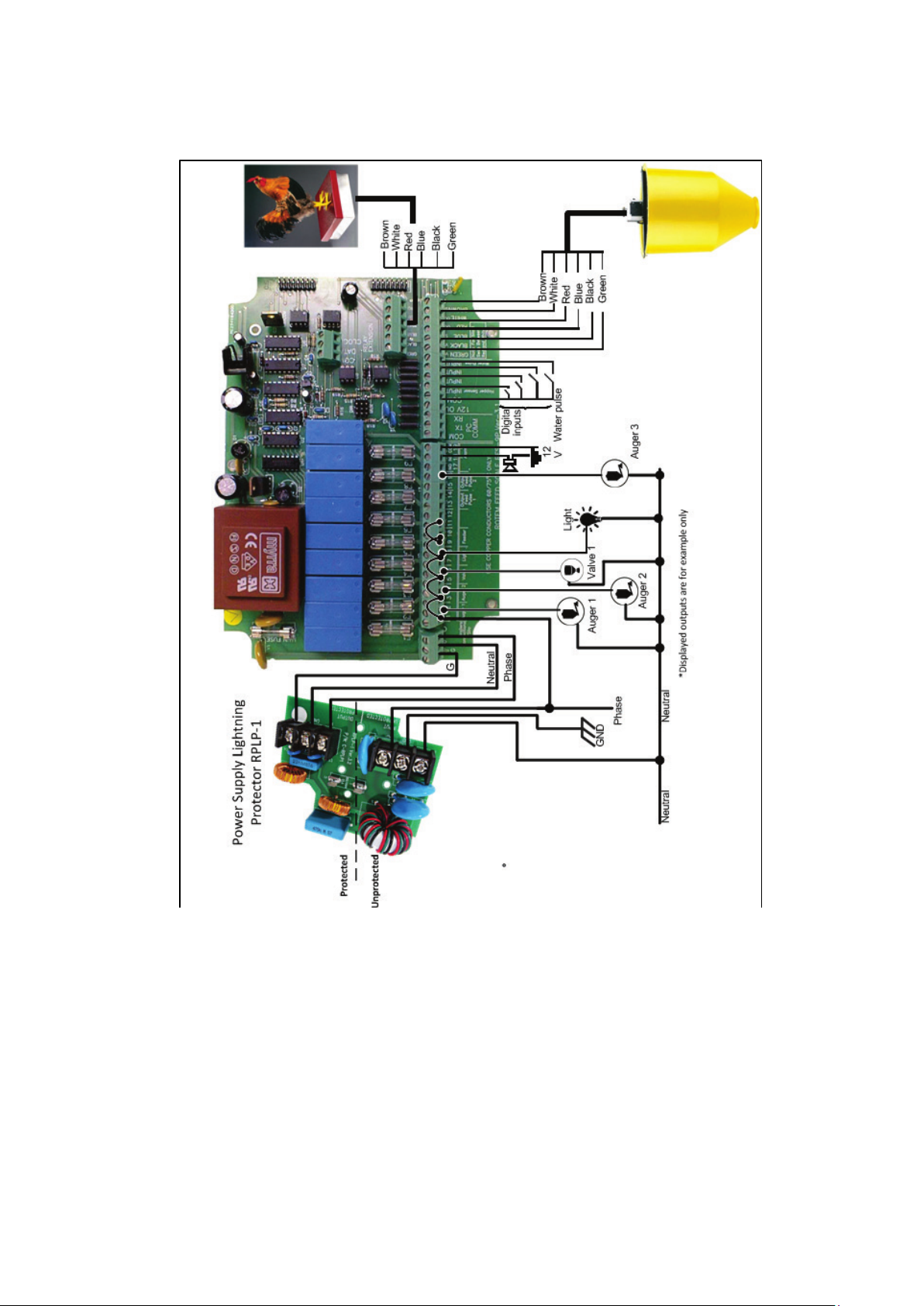
2. Position the required cables through the cable holders at the bottom of the RFS-6 Broiler
controller enclosure. Connect the wires according to the wiring diagrams. Refer to Figure 5.
NOTE: The
RFS-6 Broiler
must be installed with a
Line Protector (P/N: RPLP-1)
to provide EMI and
lightning protection for the unit’s power input. In limited cases of very noisy power lines an
isolated transformer may also be required.
The
RFS-6 Broiler
controller should be installed a proper distance from high power lines and
other electrical/mechanical equipment (i.e. Augers power, variable speed, dimmers, etc.) or
another noisy units. A distance of at least 0.5 meter distance should be maintained between
the
RFS-6 Broiler
controller and the noise source.
As the load cell cable carries mV it must be a shielded cable grounded on the
RFS-6 Broiler
side. This cable must also not be close to source of noise such as high power cables, and a
distance of at least 0.5 meter distance should be maintained.
The water pulse should also be a shielded cable grounded on one side, and kept a safe
distance from high power cables.
3. Close the RFS-6 Broiler enclosure lid carefully and tightly. Use of RTV silicon or equivalent
sealant to seal the cable holders is highly recommended.
© Munters AB, 2018 25
Page 26
4. After initial RFS-6 Broiler installation is completed, operate the RFS-6 Broiler for a test period
and check for proper operation.
Figure 5: General Wiring Diagram
© Munters AB, 2018 26
Page 27

80 cm
34 inches
60 cm
25 inches
Load Cell
Scale Valve
(S-Valve)
45 cm
19 inches
8.2 Cold Start
The Cold Start returns the values for all the parameters to the factory default and erases the history.
Perform a Cold Start
only
after changing software (EEPROM) in the RFS-6 Broiler or if there is a main
issue with the unit.
NOTE: It is strongly suggested to create a backup file of all the variables, hidden parameters, tables,
and other user programmed variables, so that they can be re-entered after a Cold Start.
NOTE: After a Cold Start you must recalibrate the feed and bird scales to retrieve the scale factors, or
to enter all factors (include the zero factor for RFS-6 Broiler) manually.
To activate a Cold Start:
•
Simultaneously press the following keypad keys: Enter, MENU, +,-, and turn off and on again
the device. The message RUN and then COLD appear on the display.
8.3 RFS-6 Broiler Container Dimensions
RFS-6 Broiler container components and dimensions are listed in Figure 6.
Figure 6: RFS-6 Broiler Container Component Dimensions
© Munters AB, 2018 27
Page 28

Scale Container
Scale Valve
Valve Motor+Load Cell
8.4 RFS-6 Broiler Container Components and Assembly
The RFS-6 Broiler container is composed of the following:
•
Scale Container
•
Valve Motor and Load
•
Scale Valve
Refer to Figure 7.
Figure 7: RFS-6 Broiler Container Components
Figure 8: Assembled RFS-6 Broiler
To assemble the RFS-6 Broiler:
1. Insert the Valve Motor and Load Cell component into the top of the Feed Container and screw it
to the container.
2. Insert the Scale Valve component at the bottom of the Scale Container and hook it onto the
Valve Motor.
© Munters AB, 2018 28
Page 29

Input Voltage Supply
Fuses
Recycle raw materials instead of disposing as waste. The controller,
8.5 Specifications
Single phase 110 VAC (USA and Canada)
Single phase 240 VAC (outside the USA and Canada)
0.315 Amps 50 - 60 Hz
Relays Outputs 5 Amps Normally Open (N.O.) Relays
Alarm Output N.O. and N.C. Pilot Duty
Operating Temperature Range 0*C to 50*C (14*F to 122*F)
Enclosure Water and dust tight (IP55)
Main Fuse: 0.315 Amps Slow
Relays Fuse: 5 Amps Slow
8.6 Environmental Protection
accessories and packaging should be sorted for environmental-friendly
recycling. The plastic components are labeled for categorized recycling.
© Munters AB, 2018 29
Page 30

9 RFS-6 Broiler Quick Guide
This section provides a basic setup guide for the RFS-6 Broiler. For a more detailed guide, refer to the
previous sections.
•
Installation
•
Calibration Menu
•
Control Menu
9.1 Installation
1. Connect the Main Silo Auger to Relay 1.
2. Connect the RFC valve to Relay 3.
3. Connect the feeder to Relay 5.
9.2 Calibration Menu
•
In Calibration > Feed Scale, calibrate the RFC-1. Refer to the manual for detailed instructions.
9.3 Control Menu
1. In Control > Feeding Curve, define the daily amount of feed to be delivered, per bird.
NOTE This process begins at midnight. To set a different time, go to Control > System Parameters >
Midnight. Set the required time to weigh the feed.
2. In Control > Feed Time, define the time period that the feeders operate (receive feed from the
hoppers) and cycle time.
3. In Control > Operation Mode, define how the feeders operate:
•
Automatically: according to RFS-6's configuration
•
Bypass: according to a fix amount (weight/time)
•
Stop: feeders cease to operate
NOTE Refer to the RFS-6 manual for details.
© Munters AB, 2018 30
Page 31

© Munters AB, 2018 31
Page 32

10 Warranty
Warranty and technical assistance
Munters products are designed and built to provide reliable and satisfactory performance but cannot be
guaranteed free of faults; although they are reliable products they can develop unforeseeable defects
and the user must take this into account and arrange adequate emergency or alarm systems if failure to
operate could cause damage to the articles for which the Munters plant was required: if this is not done,
the user is fully responsible for the damage which they could suffer.
Munters extends this limited warranty to the first purchaser and guarantees its products to be free from
defects originating in manufacture or materials for one year from the date of delivery, provided that
suitable transport, storage, installation and maintenance terms are complied with. The warranty does not
apply if the products have been repaired without express authorisation from Munters, or repaired in such
a way that, in Munters’ judgement, their performance and reliability have been impaired, or incorrectly
installed, or subjected to improper use. The user accepts total responsibility for incorrect use of the
products.
The warranty on products from outside suppliers fitted to RFS-6, (for example, power supplies, cables,
etc.) is limited to the conditions stated by the supplier: all claims must be made in writing within eight days
of the discovery of the defect and within 12 months of the delivery of the defective product. Munters has
thirty days from the date of receipt in which to take action, and has the right to examine the product at the
customer’s premises or at its own plant (carriage cost to be borne by the customer).
Munters at its sole discretion has the option of replacing or repairing, free of charge, products which it
considers defective, and will arrange for their despatch back to the customer carriage paid. In the case of
faulty parts of small commercial value which are widely available (such as bolts, etc.) for urgent
despatch, where the cost of carriage would exceed the value of the parts, Munters may authorise the
customer exclusively to purchase the replacement parts locally; Munters will reimburse the value of the
product at its cost price.
Munters will not be liable for costs incurred in demounting the defective part, or the time required to travel
to site and the associated travel costs. No agent, employee or dealer is authorised to give any further
guarantees or to accept any other liability on Munters’ behalf in connection with other Munters products,
except in writing with the signature of one of the Company’s Managers.
WARNING: In the interests of improving the quality of its products and services, Munters reserves the
right at any time and without prior notice to alter the specifications in this manual.
© Munters AB, 2018 32
Page 33

The liability of the manufacturer Munters ceases in the event of:
dismantling the safety devices;
•
use of unauthorised materials;
•
inadequate maintenance;
•
use of non-original spare parts and accessories.
•
Barring specific contractual terms, the following are directly at the user’s expense:
preparing installation sites;
•
providing an electricity supply (including the protective equipotential bonding (PE) conductor, in
•
accordance with CEI EN 60204-1, paragraph 8.2), for correctly connecting the equipment to the
mains electricity supply;
providing ancillary services appropriate to the requirements of the plant on the basis of the
•
information supplied with regard to installation;
tools and consumables required for fitting and installation;
•
lubricants necessary for commissioning and maintenance.
•
It is mandatory to purchase and use only original spare parts or those recommended by the
manufacturer.
Dismantling and assembly must be performed by qualified technicians and according to the
manufacturer’s instructions.
The use of non-original spare parts or incorrect assembly exonerates the manufacturer from all liability.
Requests for technical assistance and spare parts can be made directly to the nearest Munters office. A
full list of contact details can be found on the back page of this manual.
Munters Israel: 18 HaSivim Street
Petach-Tikva 49517, Israel
Telephone: +972-3-920-6200
Fax: +972-3-924-9834
support@munters.co.il
© Munters AB, 2018 33
Page 34

Ag/MIS/UmGB
www.munters.com
Australia Munters Pty Limited, Phone +61 2 8843 1594, Brazil Munters Brasil Industria e Comercio Ltda, Phone +55 41 3317 5050, Canada Munters Corporation
Lansing, Phone +1 517 676 7070, China Munters Air Treatment Equipment (Beijing) Co. Ltd, Phone +86 10 80 481 121, Denmark Munters A/S, Phone +45 9862
3311, India Munters India, Phone +91 20 3052 2520, Indonesia Munters, Phone +62 818 739 235, Israel Munters Israel Phone +972-3-920-6200, Italy Munters
Italy S.p.A., Chiusavecchia, Phone +39 0183 52 11, Japan Munters K.K., Phone +81 3 5970 0021, Korea Munters Korea Co. Ltd., Phone +82 2 761 8701, Mexico
Munters Mexico, Phone +52 818 262 54 00, Singapore Munters Pte Ltd., Phone +65 744 6828, South Africa and Sub-Sahara Countries Munters (Pty) Ltd., Phone
+27 11 997 2000, Spain Munters Spain S.A., Phone +34 91 640 09 02, Sweden Munters AB, Phone +46 8 626 63 00, Thailand Munters Co. Ltd., Phone +66 2
642 2670, Turkey Munters Form Endüstri Sistemleri A.Ş, Phone +90 322 231 1338, USA Munters Corporation Lansing, Phone +1 517 676 7070, Vietnam Munters
Vietnam, Phone +84 8 3825 6838, Export & Other countries Munters Italy
S.p.A., Chiusavecchia Phone +39 0183 52 11
-2244-05/15 Rev. 1.0
© Munters AB, 2018
 Loading...