

Page 1

MWI
Munters
Instruction Manual
Wall Inlet
6-pack
MWI Munters Wall Inlet
Models: MWI4108B-6PK • MWI4113B-6PK •
MWI4408B-6PK • MWI4413B-6PK
QM1115r0
1© Munters Corporation, July 2018
Page 2

MWI Munters Wall Inlet
Instructions for Use and Maintenance
Thank You:
Thank you for purchasing a Munters MWI Munters Wall Inlet. Munters equipment is designed to be the highest
performing, highest quality equipment you can buy. With the proper installation and maintenance it will provide
many years of service.
Please Note:
To achieve maximum performance and insure long life from your Munters product it is essential that it be installed
and maintained properly. Please read all instructions carefully before beginning installation.
Warranty:
For Warranty claims information see the “Warranty Claims and Return Policy” form QM1021 available from the
Munters Corporation office at 1-800-227-2376 or by e-mail at aghort.info@munters.com.
Conditions and Limitations:
• Products and Systems involved in a warranty claim under the “Warranty Claims and Return Policy” shall have
been properly installed, maintained and operated under competent supervision, according to the instructions
provided by Munters Corporation.
• Malfunction or failure resulting from misuse, abuse, negligence, alteration, accident or lack of proper installation
or maintenance shall not be considered a defect under the Warranty.
2
QM1115r0
© Munters Corporation , July 2018
Page 3

Index
Chapters Page
1. Unpacking the Equipment 4
2. Installation Instructions 6
3. Cabling 13
1.1 Parts List 4
1.2 Inlet Dimensions 5
QM1115r0
3© Munters Corporation, July 2018
Page 4

Unpacking the Equipment
1.
1.1 Parts List
Before beginning installation, check the overall condition of the equipment. Remove packing materials, and examine all
components for signs of shipping damage. Any shipping damage is the customer's responsibility and should be reported
immediately to your freight carrier.
Each Box Includes Parts to build 6 Inlets:
[A]
Each MWI Inlet Requires:
ID Qty. Cat. No. Description
1 1 Left Side End Cap, PL
2 1 Right Side End Cap, PL
3 2 Top/Bottom Header, PL
4 1 Brush Seal
5 2 2¹⁄₂” x 3⁷⁄₈” L-Screw
6 1 Door, Curved, PL
7 1 ¹⁄₂” x ¹⁄₂” Mesh Guard, GAW
Optional Lift Kit (FA1500)
A 1 AC0211/AC0212 Azuma Bolt and Nut, PL
B 1 KS2601 6 GA. x 1.875” Open Eye Lag Screw, ZP
C 1 AC1054 Nylon Guide Link
D 1 AC1039 ³⁄₁₆” Dia. Cable Clamp, ZP
E 1 AC1009 ¹⁄₈”x36”L. Braided Polyester Lift Line
[B]
[C]
[D]
[E]
4
QM1115r0
© Munters Corporation , July 2018
Page 5

1.2 Inlet Dimensions
Unpacking the EquipmentChapter 1
Door
Size Cat. No.
8”
13”
MWI4108 41” 8" 443⁄16” 111⁄8" 41⁄2” 97⁄8” 81⁄2"H. x 411⁄2"W.
MWI4408 44” 8" 473⁄16” 111⁄8” 41⁄2” 97⁄8” 81⁄2"H. x 441⁄2"W.
MWI4113 41" 13" 443⁄16" 161⁄8” 41⁄2” 147⁄8” 131⁄2”H. x 411⁄2”W.
MWI4413 44" 13" 473⁄16" 161⁄8” 41⁄2” 147⁄8" 131⁄2”H. x 441⁄2”W.
Nominal Size
A B C D E F Wall Opening
QM1115r0
5© Munters Corporation, July 2018
Page 6

Installation Instructions
2.1 Inlet Assembly
Step 1
Insert (2) Top/Bottom Header pieces onto the Right Side End Cap. See Figure 1.
Right Side End Cap
Top/Bottom Header (Bottom)
2.
Top/Bottom Header (Top)
Figure 1
Step 2
Slide the Curved Door Hinge into the rounded opening in the Bottom Header. See Figure 2.
Top/Bottom Header (Top)
Rounded Opening
Top/Bottom Header (Bottom)
Curved Door Hinge
Curved Door
6
QM1115r0
Figure 2
© Munters Corporation , July 2018
Page 7

Step 3
Press the Brush Seal into the Slot in the Top Header. See Figure 3.
Top/Bottom Header (Top)
Brush Seal
Installation InstructionsChapter 2
Figure 3
Step 4
Slide the Wire Mesh Guard into the Slot in the Top and Bottom Headers. See Figure 4.
Top/Bottom Header (Top)
Top/Bottom Header (Top)
Slot in Top
Header
Brush Seal
Wire Mesh Guard
Wire Mesh Guard
Figure 4
QM1115r0
7© Munters Corporation, July 2018
Page 8
Installation InstructionsChapter 2
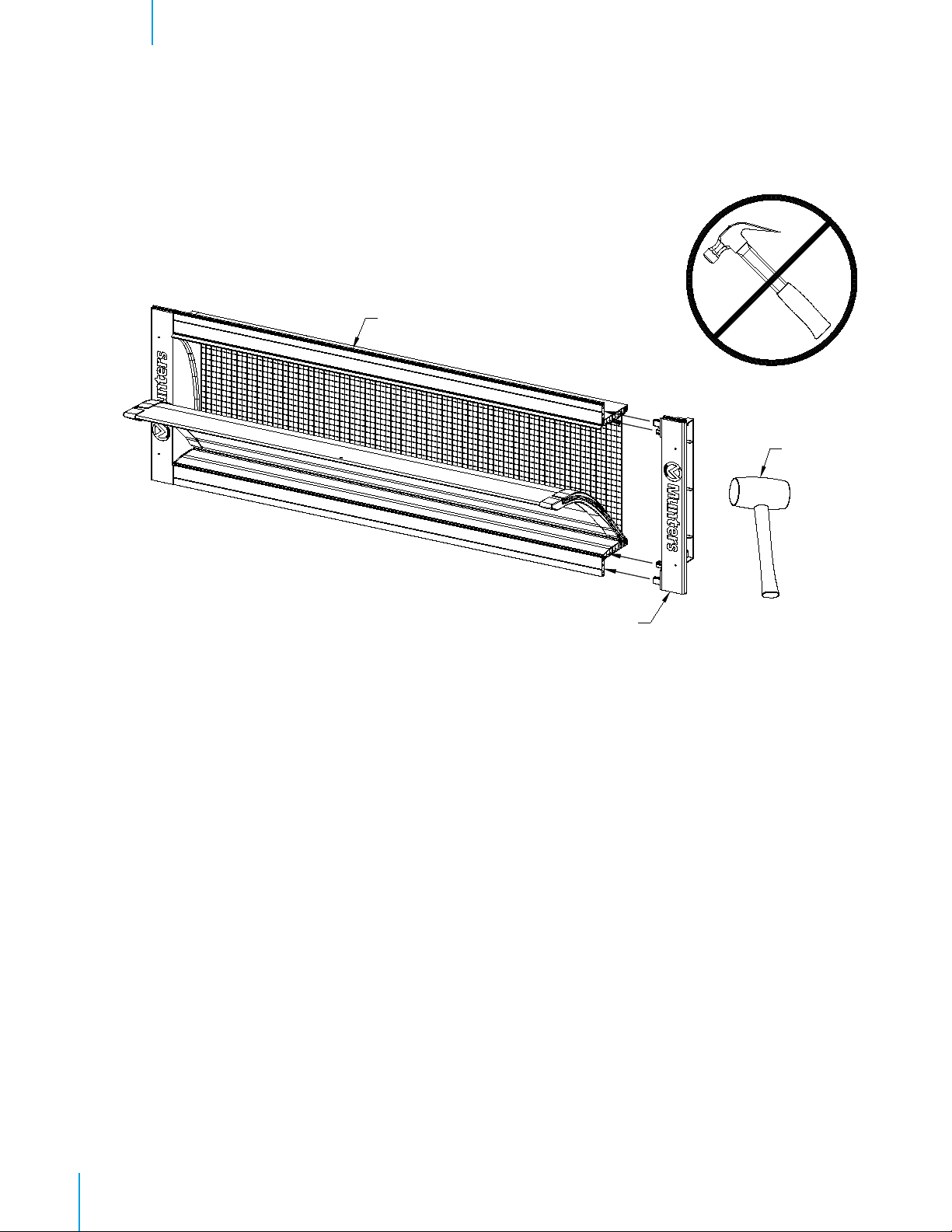
Step 5
Secure the Left Side End Cap onto the Top and Bottom Headers using a Rubber Mallet. Use caution when doing
this and NEVER use a Framing Hammer. See Figure 5.
Partially Assembled Inlet
Rubber Mallet
Figure 5
Left Side End Cap
8
QM1115r0
© Munters Corporation , July 2018
Page 9

2.2 Inlet Installation
Step 6
Construct a framed opening to correct size according to Wall Opening listed in chart on Page 5. A minimum of
10” - 12” from ceiling to the top inside of framing is required. See Figure 6A and 6B.
10" - 12" Min.
Opening
Spacer
Framed
(H.)
Framed Opening (W.)
Framed
Opening (H.)
Framed
Opening (W.)
Frame Construction
Figure 6A
Post Construction
Figure 6B
QM1115r0
9© Munters Corporation, July 2018
Page 10

Installation InstructionsChapter 2
Step 7
Slide Inlet into framed opening from inside building. See Figure 7A and 7B.
Framing
MWI Inlet
MWI Inlet
Frame Construction
Figure 7A
10
QM1115r0
Post Construction
Figure 7B
© Munters Corporation , July 2018
Page 11

Installation InstructionsChapter 2
Step 8
Secure inlet into opening using (4) Polebarn Screws or other appropriate fasteners (not provided). Locate
screws in dimples in side flanges. DO NOT overtighten screws. See Figures 8A and 8B.
Polebarn Screws (not provided)
Dimples in Flanges
Dimples in Flanges
Polebarn Screws
(not provided)
Frame Construction
Figure 8A
Post Construction
Figure 8B
QM1115r0
11© Munters Corporation, July 2018
Page 12

Installation InstructionsChapter 2
Step 9
Secure bottom header of inlet using (1) Polebarn Screws or other appropriate fasteners (not provided) in the
center of the groove of the flange. Make sure the bottom flange is straight when fastening. Push up slightly on
center of top header ¹⁄₄” or 0.6cm and secure using (1) Polebarn Screw (not provided). DO NOT overtighten
screws. See Figures 9A and 9B.
Polebarn Screws (not provided)
Groove in fl ange
Groove in fl ange
Polebarn Screws (not provided)
Frame Construction
Figure 9A
12
QM1115r0
Post Construction
Figure 9B
© Munters Corporation , July 2018
Page 13

Cabling
Step 10
Attach pulleys in line with screw hooks at each endwall. See Figure 10A and 10B.
Ceiling
3.
SPRING END
AC1264 Single Pulley
Bracket. Provide adequate
support.
Figure 10A
Truss
AC1039 Cable Clamps. Thread cable
through loop at end of spring and
fasten with (2) cable clamps.
WINCH/ ACTUATOR END
Building Wall
Fasten spring into stud with lag
screw or bolt and nut.
AC1195 Baffl e return spring
SPRING TENSION:
with baffl e fully closed and cable pulled tight,
stretch spring 12" - 14" and fasten.
AC1264 Single Pulley Bracket.
Recess pulley into ceiling in order
to keep cable in line with rod.
Figure 10B
AC1013 or
AC1044 Cable
Building Wall
Ceiling
QM1115r0
13© Munters Corporation, July 2018
Page 14

CablingChapter 3
Step 11
Install Screw Hooks 2” above top flange of Inlet, in line with Lift Line hole in door. See Figures 11A and 11B.
For Post Frame Construction, also, install a screw hook on each post near ceiling. See Figure 11C.
Flange of Inlet
2”
Screw Hook
Lift Line Hole
in Door
Figure 11A Figure 11B
Screw Hook
Flange of Inlet
14
QM1115r0
Screw Hook
Figure 11C
© Munters Corporation , July 2018
Page 15

CablingChapter 3
Step 12
Pull main rod or cable from winch or actuator through pulleys and screwhooks to weights or return spring on
opposite end wall. See Figures 10A, 10B, 12A and 12B. Be sure to coil approximately 1' of cable on winch.
Screw Hook
Main Rod
or Cable
Main Rod or Cable
Figure 12A
Screw Hook
Figure 12B
QM1115r0
15© Munters Corporation, July 2018
Page 16

CablingChapter 3
Note: If optional kit, Lift Package (FA1500) was purchased, hardware mentioned below in Step 13 is included. If
not purchased, hardware provided by others.
Step 13
Put a Nylon Guide Link [C] (black) on each Screw Hook [B] that is directly above the center of each inlet.
Attach one Lift Line [E] to Main Cable using (1) Cable Clamp [D]. Lift line should be attached 14” back
from hook toward the winch end. Run each lift line through the adjacent Nylon Guide Link [C] and attach
Azuma Bolt and Nut [A]. See Figure 13A and 13B.
Cable Clamp [D]
Figure 13A
Eye Screw [B]
Nylon Guide Link [C]
Lift Line [E]
Azuma Bolt & Nut [A]
16
QM1115r0
© Munters Corporation , July 2018
Page 17

CablingChapter 3
Cable Clamp [D]
Figure 13B
Eye Screw [B]
Nylon Guide Link [C]
Lift Line [E]
Azuma Bolt & Nut [A]
QM1115r0
17© Munters Corporation, July 2018
Page 18

CablingChapter 3
Step 14
With the winch at its fully closed position, go back, check and readjust each baffle door tightly to inlet frame.
Use winch or baffle machine to open and close inlets a few times to make sure baffle moves smoothly and
each door remains even over the total length of house. See Figure 14.
To Weights or
Return Spring
Figure 14
Step 15
Locate (2) L-Screws ¹⁄₂” [1.2cm] above Top Header and evenly space across the inlet. Thread L-Screws in far
enough to hold the door in the close position. Make sure L-Screw does not interfere with the Lift Line or Main
Rod or Cable. See Figure 15A and 15B.
L-Screw (provided)
18
QM1115r0
Figure 15A
© Munters Corporation , July 2018
Page 19

L-Screw (provided)
CablingChapter 3
UNLATCHED POSITION
L-Screw (provided)
LATCHED POSITION
Figure 15B
QM1115r0
19© Munters Corporation, July 2018
Page 20

MWI Inlets are Sold by Munters Corporation, Lansing, Michigan U.S.A. 1-800-227-2376
Munters Europe AB, Isafjordsgatan 1, P.O. Box 1150, SE-164 26 Kista, Sweden. Phone +46 08 626 63 00, Fax +46 8 754 56 66.
Munters Corporation 2691 Ena Drive Lansing, MI 48917 U.S.A. Phone +1 800-227-2376, Fax +1 517-676-7078
www.munters.us
Australia Munters Pty Limited, Phone +61 2 6025 6422, Brazil Munters Brasil Industria e Comercio Ltda, Phone +55 41 3317 5050, Canada/US Munters
Corporation Lansing, MI Phone +1 517 676 7070, China Munters Air Treatment Equipment (Beijing) Co. Ltd, Phone +86 10 80 481 121, Denmark Munters A/S,
Phone +45 9862 3311,
Phone +39 0183 52 11, Japan Munters K.K., Phone +81 3 5970 0021, Korea Munters Korea Co. Ltd., Phone +82 2 761 8701, Mexico Munters Mexico, Phone
+52 818 262 54 00, Russia Munters AB, Phone +7 812 448 5740, Singapore Munters Pte Ltd., Phone +65 744 6828, South Africa and Sub-Sahara Countries
Munters (Pty) Ltd., Phone +27 11 997 2000, Spain Munters Spain S.A., Phone +34 91 640 09 02, Sweden Munters AB, Phone +46 8 626 63 00, Thailand
Munters Co. Ltd., Phone +66 2 642 2670, Turkey Munters Form Endüstri Sistemleri A.Ş, Phone +90 322 231 1338, USA Munters Corporation Lansing, MI Phone
+1 517 676 7070, Vietnam Munters Vietnam, Phone +84 8 3825 6838, Export & Other countries Munters Italy S.p.A., Chiusavecchia Phone +39 0183 52 11
India Munters India, Phone +91 20 3052 2520, Indonesia Munters, Phone +62 818 739 235, Italy Munters Italy S.p.A., Chiusavecchia,
20
QM1115r0
© Munters Corporation , July 2018
 Loading...