

Page 1
ENGLISH
Dehumidifier ML420-1350,
MLT800-1400
User manual
T-ML2-A1904
Page 2

Copyright © 2019 Munters Europe AB
Original instructions
Valid for units produced from April 2019.
IMPORTANT
Read these instructions before using the product.
Page 3

Dehumidifier ML420-1350, MLT800-1400
Table of Contents
1. Important user information .................................................................................................. 5
1.1. Intended use ........................................................................................................... 5
1.2. Warranty ................................................................................................................. 5
1.3. Safety information ................................................................................................... 5
1.4. Copyright ................................................................................................................ 6
2. Introduction ....................................................................................................................... 7
2.1. About this manual ................................................................................................... 7
2.2. Unintended use ....................................................................................................... 7
2.3. Safety ..................................................................................................................... 7
2.4. Marking .................................................................................................................. 9
3. Dehumidifier design ......................................................................................................... 10
3.1. Product description ................................................................................................ 10
3.2. Function overview ................................................................................................. 10
3.3. Main components .................................................................................................. 11
3.4. Insulated process air inlet ...................................................................................... 11
4. Transport, delivery inspection and storage ......................................................................... 12
4.1. Transport .............................................................................................................. 12
4.2. Delivery inspection ................................................................................................ 12
4.3. Storage ................................................................................................................ 12
5. Installation ....................................................................................................................... 13
5.1. Safety ................................................................................................................... 13
5.2. Installation site requirements .................................................................................. 13
5.3. Foundation ........................................................................................................... 14
5.4. Duct installation ..................................................................................................... 14
5.4.1. General recommendations .......................................................................... 14
5.4.2. Duct for outdoor air inlet .............................................................................. 16
5.4.3. Duct for wet air outlet .................................................................................. 16
5.5. Precautionary measures for units with lithium chloride rotor ..................................... 17
5.6. Electrical installation .............................................................................................. 17
5.7. External humidity sensor ........................................................................................ 18
6. Commissioning ................................................................................................................ 19
6.1. Inspection before first start ..................................................................................... 19
6.2. Function test ......................................................................................................... 20
6.3. Airflow adjustment ................................................................................................. 20
7. Operation ........................................................................................................................ 21
7.1. Main power switch ................................................................................................. 21
7.2. Control system ...................................................................................................... 21
7.3. Start and stop ....................................................................................................... 21
7.3.1. Start/stop from control system panel ............................................................ 22
7.3.2. Start/stop with mode selector ...................................................................... 22
8. Service and maintenance ................................................................................................. 23
8.1. Safety ................................................................................................................... 23
8.2. General ................................................................................................................ 23
8.3. Extended warranty ................................................................................................ 23
8.4. Service alternatives ............................................................................................... 23
8.5. Maintenance schedule ........................................................................................... 24
8.6. Preventive replacements ....................................................................................... 25
8.7. Filter change ......................................................................................................... 25
8.8. Cleaning ............................................................................................................... 25
9. Technical specification ...................................................................................................... 26
9.1. Dimensions and service space ............................................................................... 26
9.2. Capacity diagrams ................................................................................................ 27
9.3. Technical data ....................................................................................................... 29
3
Page 4

Dehumidifier ML420-1350, MLT800-1400
9.4. Sound data ........................................................................................................... 30
9.4.1. Definition ................................................................................................... 30
9.4.2. Sound data ML420 ..................................................................................... 31
9.4.3. Sound data ML690 ..................................................................................... 31
9.4.4. Sound data MLT800 ................................................................................... 32
9.4.5. Sound data ML1100 .................................................................................... 32
9.4.6. Sound data ML1350 ................................................................................... 33
9.4.7. Sound data MLT1400 ................................................................................. 33
10. Disposal ........................................................................................................................ 34
11. Contact Munters ............................................................................................................. 35
4
Page 5
Dehumidifier ML420-1350, MLT800-1400
1. Important user information
1.1. Intended use
Munters dehumidifiers are intended to be used for the dehumidification of air. Any other use of the unit,
or use which is contrary to the instructions given in this manual, can cause personal injury and damage
to the unit and other property.
No modification of the unit is allowed without prior approval by Munters. Installation of additional devices is only allowed after written agreement by Munters.
1.2. Warranty
The warranty is based on the terms of sale and delivery of Munters. The warranty is not valid if repairs
or modifications are carried out without the written agreement of Munters, or if the unit does not operate
under the conditions agreed with Munters.
The warranty is limited to a free exchange of parts or components which have failed as a result of defects in materials or workmanship.
All warranty claims must include proof that the fault has occurred within the warranty period and that the
unit has been used in accordance with the specifications. All claims must specify the unit type and serial
number. This information is stamped on the identification label.
Commissioning/Start-up inspection "S" by Munters is mandatory to validate the full warranty.
It is a condition of the warranty that the unit for the full warranty period is serviced and maintained by a
qualified Munters engineer or Munters approved engineer. The service and maintenance must be documented for the warranty to be valid.
1.3. Safety information
Information about dangers are in this manual indicated by the common hazard symbol:
WARNING
Indicates a possible danger that can lead to personal injury.
CAUTION
Indicates a possible danger that can lead to damage to the unit or other property, or
cause environmental damage.
NOTE
Highlights supplementary information for optimal use of the unit.
5
Page 6

Dehumidifier ML420-1350, MLT800-1400
1.4. Copyright
The contents of this manual can be changed without prior notice.
NOTE
This manual contains information which is protected by copyright laws. It is not allowed
to reproduce or transmit any part of this manual without written consent from Munters.
Munters Europe AB, P.O. Box 1150, SE-16426 KISTA Sweden
6
Page 7

Dehumidifier ML420-1350, MLT800-1400
2. Introduction
2.1. About this manual
This manual is written for the user of the dehumidifier. It contains necessary information for how to install and use the dehumidifier in a safe and efficient way.
Read through the manual before the dehumidifier is installed and used.
Contact your nearest Munters office if you have any questions about the installation or the use of your
dehumidifier.
This manual must be stored in a permanent location close to the dehumidifier.
2.2. Unintended use
The following restrictions on use apply:
• The dehumidifier is not intended for outdoor installation.
• The dehumidifier is not intended for use in classified areas where explosion safety compliant equipment is required.
• The dehumidifier must not be installed near any heat generating devices that can cause damage to
the equipment.
2.3. Safety
The information in this manual shall in no way take precedence over individual responsibilities or local
regulations.
During operation and other work with a machine it is always the responsibility of the individual to consider:
• The safety of all persons concerned.
• The safety of the unit and other property.
• The protection of the environment.
7
Page 8

Dehumidifier ML420-1350, MLT800-1400
WARNING
• All electrical installations must be done by an authorized electrician in accordance
with local regulations. An incorrect installation can cause electrical shock hazards
and damage to the unit.
• Commissioning and initial start-up of the unit must be done by authorized personnel
only.
• The unit must never be connected to another voltage or frequency than what is
specified on the identification plate. Too high line voltage can cause electrical shock
hazards and damage to the unit.
• Rotating fan blades can cause serious injury. Only operate the unit with the air ducts
connected.
• The unit can restart automatically after a power cut. Make sure that the main power
switch is set and locked in the OFF position before any service or maintenance work
starts.
• Use only approved lifting equipment to prevent personal injury and damage to the
unit.
• Move the unit carefully to prevent it from overturning.
• If the rotor is to be cut in pieces, wear a suitable CE marked face mask selected and
fitted in accordance with the applicable safety standards to protect from the dust.
8
Page 9
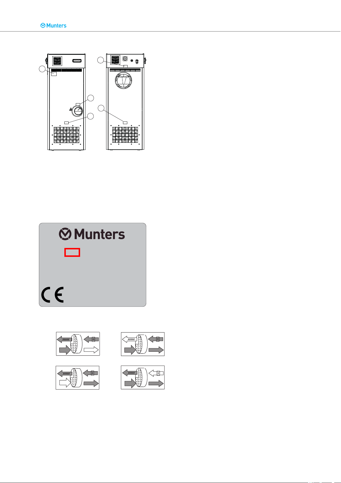
2.4. Marking
1
3
5
4
2
Fabr. No. 1835 XXXXXX XXXXXX
Munters Europe AB
P.O. Box 1150
164 26 Kista, Sweden
Fabr. year
Made in Sweden
2018
3
2
4
3
5
4
2 3
5
1. Unit identification plate
2. Dry air outlet
3. Wet air outlet
4. Process air inlet
5. Reactivation air inlet
Dehumidifier ML420-1350, MLT800-1400
Example identification plate. The first four digits in the fabrication number indicate year and week
(YYWW) of production for the unit.
Labels:
9
Page 10
1
3
4
Dehumidifier ML420-1350, MLT800-1400
3. Dehumidifier design
3.1. Product description
The desiccant dehumidifiers in the ML series have been developed to effectively dehumidify the air in
environments requiring low air humidity.
The dehumidifier is equipped with an encapsulated rotor unit. The rotor casing is constructed of durable
thermoset plastic and contains isolated sections that provide a precise balance for the dehumidification,
reactivation and heat recovery airflows.
The dehumidifier is manufactured in accordance with uniform European standards and established requirements for CE-marking.
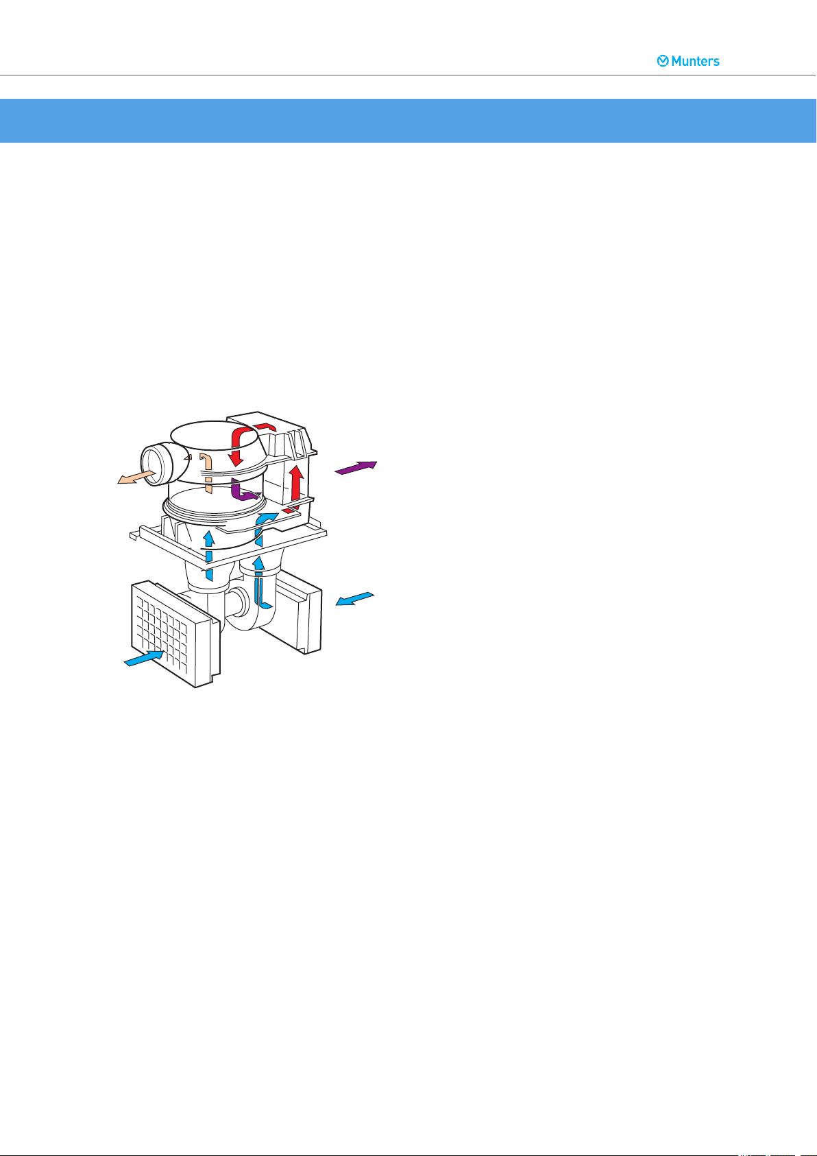
3.2. Function overview
Internal airflows
1. Process air
2. Dry air
3. Reactivation air
4. Wet air
The desiccant rotor is the adsorption dehumidifying component in the unit. The rotor structure is comprised of a large number of small air channels.
The desiccant rotor is made of a composite material that is highly effective in attracting and retaining
water vapour. The rotor is divided in two zones.
The airflow to be dehumidified, process air, passes through the largest zone of the rotor and then
leaves the rotor as dry air. Since the rotor rotates slowly, the incoming air always meets a dry zone on
the rotor, thus creating a continuous dehumidification process.
The airflow used to dry the rotor, reactivation air, is heated. The reactivation air passes through the
rotor in the opposite direction to the process air and leaves the rotor as wet air (warm, moist air).
This principle enables the dehumidifier to work effectively, even at freezing temperatures.
10
Page 11
1
2
3
4
5
8
7
6
9
Dehumidifier ML420-1350, MLT800-1400
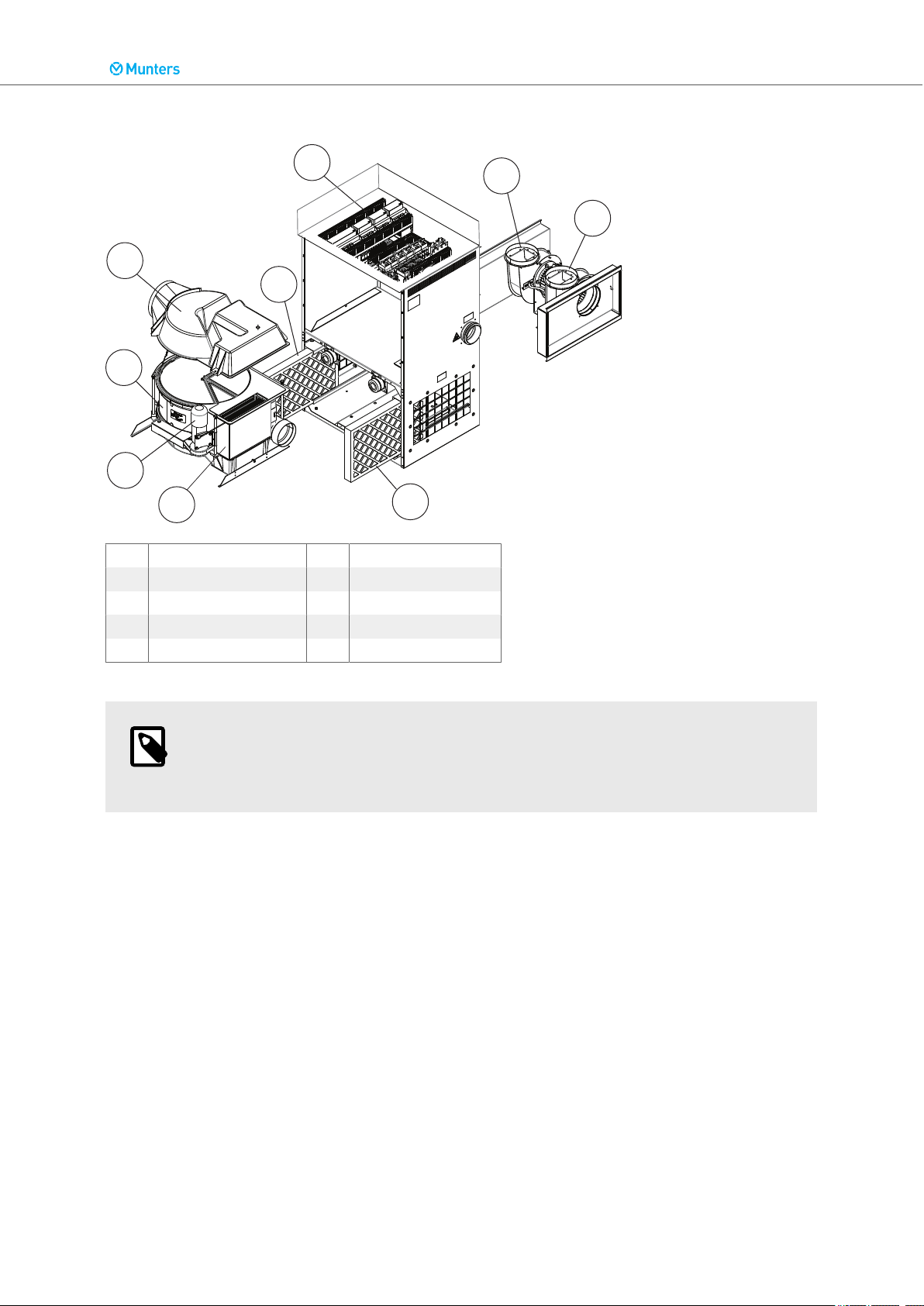
3.3. Main components
1. Electrical panel 6. Reactivation heater
2. Process fan 7. Drive motor
3. Reactivation fan 8. Rotor
4. Reactivation air filter 9. Upper rotor cover
5. Process air filter
NOTE
The ML420 unit has only one fan motor that is placed between the process and reactivation impellers.
3.4. Insulated process air inlet
When cold process air is to be dehumidified, often in conjunction with a pre-cooler, condensate will
readily form on the inlet side of the dehumidifier. ML-series dehumidifiers can therefore be supplied in
an IPI version in which the process air fan is encased in a specially insulated box to prevent the formation of condensation.
11
Page 12

Dehumidifier ML420-1350, MLT800-1400
4. Transport, delivery inspection and storage
4.1. Transport
The dehumidifier is delivered on a pallet and must be handled carefully. All panel doors on the unit must
be closed during transport. Provided that the dehumidifier is still secured to its delivery pallet, it can be
moved using a fork-lift truck.
WARNING
Move the unit carefully to prevent it from overturning.
Weight of the dehumidifier can be found in section Technical data.
4.2. Delivery inspection
• Do an inspection of the delivery and compare with the delivery note, order confirmation or other delivery documentation. Make sure that everything is included and nothing is damaged.
• Contact Munters immediately if the delivery is not complete or damaged in order to avoid installation
delays.
• Any damage to the packaging must be documented with photos before the packaging is removed.
• Remove all packaging material from the unit, and make sure that no damage has been made during
transportation.
• Any damage to the unit must be documented with photos.
• Any visible damage must be reported in writing to Munters within 3 days and prior to installation of the
unit.
• Discard the packaging material according to local regulations.
4.3. Storage
Follow these instructions if the dehumidifier is to be stored prior to installation:
• Place the dehumidifier in an upright position on a horizontal surface.
• Re-use the packaging material to provide protection for the unit.
• Protect the dehumidifier from physical damage.
• Store the dehumidifier under cover and protect it from dust, rain and aggressive contaminants.
12
Page 13

5. Installation
5.1. Safety
WARNING
• All electrical installations must be done by an authorized electrician in accordance
with local regulations. An incorrect installation can cause electrical shock hazards
and damage to the unit.
• The unit must never be connected to another voltage or frequency than what is
specified on the identification plate. Too high line voltage can cause electrical shock
hazards and damage to the unit.
• Move the unit carefully to prevent it from overturning.
• Use only approved lifting equipment to prevent personal injury and damage to the
unit.
• Rotating fan blades can cause serious injury. Only operate the unit with the air ducts
connected.
Dehumidifier ML420-1350, MLT800-1400
CAUTION
Do not sit, stand, or place any objects on the unit.
5.2. Installation site requirements
NOTE
It is important that the intended installation site meets the location and space requirements for the equipment in order to achieve the best possible performance and trouble-free operation.
It is important for maintenance purposes to obey the minimum service space requirements.
The dehumidifier is only intended for indoor installation.
For space requirements, see section Dimensions and service space.
NOTE
If there is a need for reduction of vibrations from the dehumidifier, contact Munters for
instructions.
13
Page 14
427
81
51
613
Ø7(4x)
Dehumidifier ML420-1350, MLT800-1400
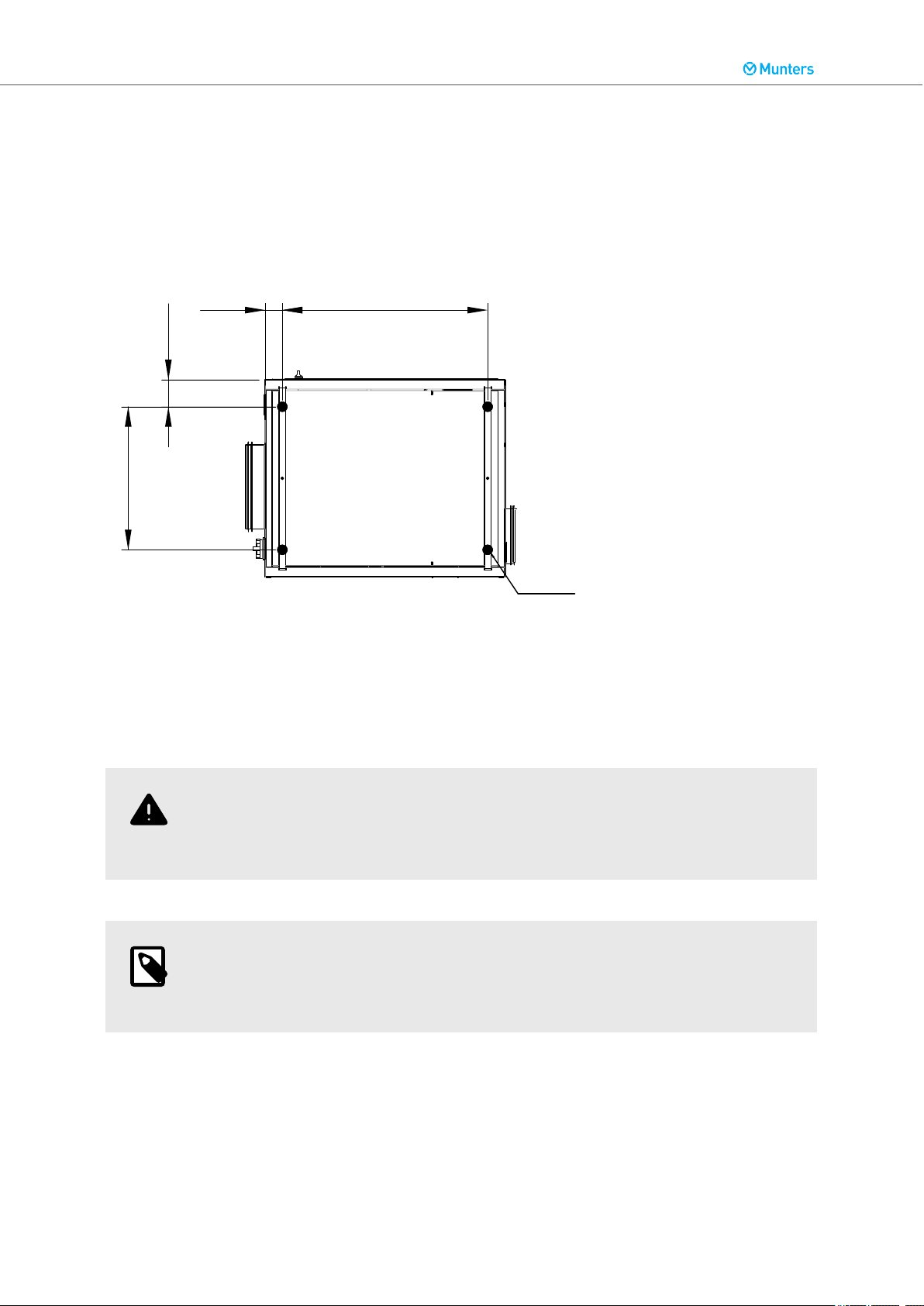
5.3. Foundation
The dehumidifier must be installed on a level floor, or platform, which has been designed with a floor
loading capacity capable of supporting the total weight of the unit. If the maximum floor loading weight
is not exceeded, special foundations are not required.
If local regulations require that the unit must be attached to the floor, the mounting holes in the base
frame can be used for foundation screws.
5.4. Duct installation
5.4.1. General recommendations
The connections for process and reactivation air are designed in accordance with the recommendations
in ISO 13351. The rectangular duct connections contain tapped inserts for M8 screws.
WARNING
The dehumidifier has been designed to operate at specific process airflows corresponding to the fan sizes installed.
NOTE
The IPI version does not have a process air filter. The process air inlet must therefore
be connected to cold/pre-cooled and filtered air via a duct.
• The length of ductwork must be kept as short as possible to minimize static air pressure losses.
• To maintain performance, all rigid process or reactivation air ductwork joints must be air and vapour
tight.
• The process air ductwork must be insulated to prevent condensation developing on the outside of the
duct, whenever the temperature of the air within the duct falls below the dewpoint temperature of the
ambient air through which the ductwork is routed.
14
Page 15

ML
Munter s
420
1
2
3
5
5
4
C
B
D
A
Dehumidifier ML420-1350, MLT800-1400
• The ducts must always be insulated when there is a risk of freezing.
• The wet air leaving the dehumidifier will, because of high moisture content, condense on the inside
duct walls. By insulating the ducts, the amount of condensate is reduced.
• Horizontal wet air ducts must be installed with a slight decline (away from the dehumidifier) to drain
away possible condensation. Suitable condensation drains must be installed at low points in the wet
air outlet duct.
• Ensure that access for operation and servicing is not restricted when designing and installing ducting.
• To reduce noise and/or vibration being transmitted along rigid ducts, good quality, airtight flexible connections must be fitted.
• Ducts mounted directly onto the unit must be independently supported to minimize the load on the
unit.
• Dampers for adjustment of the airflows must be installed in the dry air outlet and reactivation air inlet
ducts. Correct airflows are essential for the efficiency of the unit.
• The total pressure drop in the process and reactivation ductwork must not exceed the available pressure of the fans fitted to the dehumidifier.
Ducts required for installation
A. Process air inlet 1. Dry air damper
B. Dry air outlet 2. External filter box (option)
C. Reactivation air inlet 3. Duct transition
D. Wet air outlet 4. Reactivation air damper
5. Outlet/inlet duct (wire netting)
15
Page 16

1
2
3
3
1
2
3
3
4
4
5
Dehumidifier ML420-1350, MLT800-1400
5.4.2. Duct for outdoor air inlet
When bringing outside ambient air into the dehumidifier, the opening to the inlet duct should be located
sufficiently high above ground level to prevent the pick up of dust and debris. The ducting should be
designed to prevent rain and snow from being drawn into the dehumidifier. The air inlet must be located
away from possible contaminants such as engine exhaust gases, steam and harmful vapours.
To prevent the wet air from humidifying the reactivation air, the air inlet for reactivation must be located
at least 2 m from the wet air outlet.
Attach a wire net with a mesh width of approximately 10 mm in the outer end of the duct to prevent
animals from entering the dehumidifier ducting.
1. Rectangular ducting
2. Round ducting
3. Wire netting
5.4.3. Duct for wet air outlet
The material for the wet air duct must withstand corrosion and temperatures of up to 100 °C. The wet
air ducting must always be insulated if there is a risk of condensation. The wet air leaving the dehumidifier will easily cause condensation on the inside of the duct walls due to the high moisture content.
Horizontal ducts must be installed sloping downwards (away from the dehumidifier) to drain away possible condensation. The duct slope must be at least 2 cm/m. In addition, drainage holes (5 mm) should be
made at low points in the duct to prevent water accumulation.
Attach a wire net with a mesh width of approximately 10 mm in the outer end of the duct to prevent
animals from entering the dehumidifier ducting.
1. Horizontal wet air outlet
2. Vertical wet air outlet
3. Wire netting
4. Downward slope
5. Condensate drainage
16
Page 17

Dehumidifier ML420-1350, MLT800-1400
5.5. Precautionary measures for units with lithium chloride rotor
The standard delivery is Munters high performance desiccant rotor HPS (High Performance Silica gel).
If the dehumidifier is delivered with an LI rotor (lithium chloride) it is important that the rotor does not
become loaded with moisture when the dehumidifier is off.
CAUTION
Make sure that no air passing through the rotor has a relative humidity greater than
80%.
It is recommended to install closing dampers in the process and reactivation air inlets to avoid that air
with high relative humidity is drawn through the rotor and into the room.
This is particularly important when the process air is drawn from outdoors, or when the system has
been fitted with a pre-cooler.
5.6. Electrical installation
WARNING
All electrical installations must be done by an authorized electrician in accordance with
local regulations. An incorrect installation can cause electrical shock hazards and damage to the unit.
WARNING
The unit must never be connected to another voltage or frequency than what is specified on the identification plate. Too high line voltage can cause electrical shock hazards
and damage to the unit.
CAUTION
The supply voltage must not differ from the specified operating voltage by more than ±
10 %.
The dehumidifier is delivered complete with all internal wiring installed and configured for the voltage
and frequency specified on the identification plate.
The mains power supply is connected directly to the main power switch in the unit. The supply cable
and main fuses must be rated for the unit.
17
Page 18

Dehumidifier ML420-1350, MLT800-1400
NOTE
If the unit is connected to the power after an RCD (Residual Current Device), also
known as an earth fault breaker, this must be of “industrial” type B typically with a sensitivity of 100 mA or greater to avoid any unwanted tripping.
Maximum permissible system impedance 0.01 Ohm.
For connection details, see the identification plate and the wiring diagram.
5.7. External humidity sensor
The dehumidifier is normally delivered with a humidity sensor.
The sensors have an output signal of 4... 20 mA for temperature and humidity respectively.
Depending on the control system, some of these options are available:
• Sensor for relative humidity in wall mounted version. The measurement range for humidity is 0... 100
% RH. The measurement range for temperature is -5...+55 °C.
• Sensor for relative humidity in duct mounted version. The measurement range for humidity is 0... 100
% RH. The measurement range for temperature is -20...+80 °C.
• Dewpoint sensor. The measurement range for dewpoint temperature is -80...+20 °C.
• Sensor for absolute humidity, duct mounted. The measurement range is 0... 20 g/kg.
The humidity sensor regulates the dehumidifier when the mode switch is in the AUTO position (automatic mode) and also indicates current humidity.
To ensure correct operation, the humidity sensor must be connected with a shielded 5G, 0.75 mm² electric cable.
When placed on a wall, the humidity sensor must be mounted 1–1.5 m above the floor. It must be positioned so that it is not directly exposed to dry air from the unit, or humid air flowing in through doors that
are opened and closed. It must not be placed close to a heat source or be exposed to direct sunlight.
A duct mounted sensor must be installed far enough from the unit outlet to get a stable humidity reading.
For more information, see the assembly instruction delivered with the humidity sensor.
18
Page 19

Dehumidifier ML420-1350, MLT800-1400
6. Commissioning
WARNING
Commissioning and initial start-up of the unit must be done by authorized personnel
only.
WARNING
Rotating fan blades can cause serious injury. Only operate the unit with the air ducts
connected.
CAUTION
The airflows must never be set above the rated airflows without consulting Munters for
verification.
CAUTION
Incorrect adjustment of the airflows can cause malfunction of the unit. Any damage to
the unit resulting from incorrect adjustment of the airflows can invalidate the warranty
of the unit.
6.1. Inspection before first start
1. Make sure that the main power switch is set to position O.
2. Open the cover for the electrical panel and make sure that no circuit breakers or automatic fuses
have released.
3. Examine the air intake filters and make sure that they are undamaged and correctly installed, and
that all areas inside the different unit sections are clean.
4. Examine all ducts and duct connections and make sure that all connections have been correctly in-
stalled, and that there are no signs of damage. Make sure that all ducts are free from unwanted
material blocking the air passage.
5. Make sure that the incoming power supply voltage is correct and that the cables are correctly con-
nected.
6. Make sure that the humidity sensor is correctly positioned, and correctly connected to the electrical
panel.
19
Page 20

Dehumidifier ML420-1350, MLT800-1400
6.2. Function test
1. Set the main power switch to position 1.
2. Start the unit.
3. Make sure that the rotor rotates in the direction indicated by the arrows. If the direction of rotation is
wrong, interchange the connections for the incoming wires in the main power switch.
6.3. Airflow adjustment
To obtain optimal performance, the process and reactivation airflows must be correctly adjusted.
Contact Munters for help with installation and settings.
1. Adjust the dampers installed in the dry air outlet and reactivation air inlet ducts to the correct rated
airflows.
2. Start the dehumidifier and run at full power for 8 minutes to allow the reactivation heater to reach its
normal operating temperature.
3. Make sure that the temperature difference between the reactivation inlet air and the reactivation
temperature is 95 °C (tolerance limit ±5 °C). If the temperature difference lies outside of the 5% tolerance limit, the reactivation air damper can be adjusted in small steps until the reactivation temperature is within the specified tolerances. Allow the temperature to stabilize after each adjustment.
EXAMPLE: Inlet air temperature 15 °C and reactivation air temperature 110 °C = temperature increase
95 °C.
20
Page 21
o
OFF
o
1
ON
OFF
SIEMENS
Dehumidifier ML420-1350, MLT800-1400
7. Operation
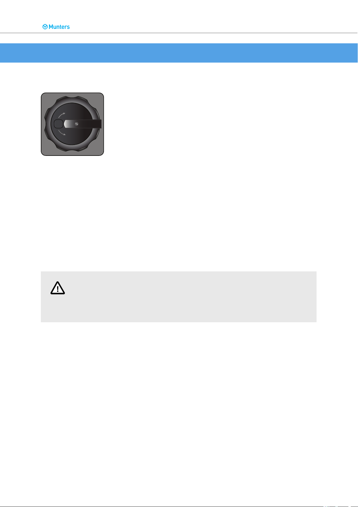
7.1. Main power switch
Main power switch
• When the main power switch is set to position O, the unit is not powered beyond the switch.
• When the main power switch is set to position 1, the unit is powered and can be started.
7.2. Control system
For more information about the control system, parameters and settings, see the control system supplement.
7.3. Start and stop
Start and stop of the unit is controlled from the control system panel with AirC control system, or with
the mode selector for Climatix control system.
CAUTION
In order to dissipate any residual heat, the fans and the drive motor continue to run after the unit is switched off until the temperature falls below 50 °C. Do not turn off the
main power before the fans have come to a complete stop.
21
Page 22

0
Dehumidifier ML420-1350, MLT800-1400
7.3.1. Start/stop from control system panel
Press the start/stop button in the upper right corner to operate the unit.
• From Off, press once to go to Automatic mode, with sensor control.
• From Off or Automatic, press and hold for more than 3 seconds to go to Manual mode, 100% capacity dehumidification.
• From Automatic or Manual, press once to go to Off.
7.3.2. Start/stop with mode selector
Only with Climatix control system.
When the mode selector is set to position AUTO, the dehumidifier is controlled to an internal adjustable
humidity setpoint, or via an external input signal.
When the mode selector is set to position MAN, the fans, rotor and reactivation heater run continuously
at full capacity.
22
Page 23

Dehumidifier ML420-1350, MLT800-1400
8. Service and maintenance
8.1. Safety
WARNING
The unit can restart automatically after a power cut. Make sure that the main power
switch is set and locked in the OFF position before any service or maintenance work
starts.
WARNING
Rotating fan blades can cause serious injury. Only operate the unit with the air ducts
connected.
8.2. General
Service and maintenance interval lengths are primarily determined by operating conditions and the environment in which the unit is installed. For example, if the process air contains a lot of dust, preventative maintenance should be carried out at shorter intervals. The same also applies if the unit works intensively.
The control system is equipped with a service indicator. It is programmed at commissioning to give a
service alarm after an estimated number of operating hours, or on the preset date for the next service.
Munters offers a comprehensive range of services, from commissioning and start-up to advanced maintenance packages. More information can be obtained from the local Munters representative.
8.3. Extended warranty
Munters offers an extended warranty to the standard terms when the Customer signs a service agreement with Munters. Details are available on request.
8.4. Service alternatives
In addition to commissioning (S) of the unit there are four service alternatives (A - D) as standard.
A - Inspection and if necessary change of filter. General function inspection.
B - In addition to A, safety inspection and capacity, temperature and humidity regulation measurements.
C - In addition to B, preventive replacement of some components after 3 years of operation.
D - In addition to C, preventive replacement of some components after 6 years of operation.
23
Page 24

Dehumidifier ML420-1350, MLT800-1400
NOTE
It is recommended to contact Munters for service or repair. Operating faults can occur
if the unit is maintained insufficiently or incorrectly.
8.5. Maintenance schedule
Service alternative
Operating time
[hours]
Calendar time
[months]
Inspection of filter, replace if necessary
Capacity measurement, rotor inspection
Preventive inspection incl.
safety and function test
Function test of
electrical and
control system
Inspection of
fans, impellers,
motors, bearings
Inspection of rotor housing, replace rotor gaskets if necessary
1
Replace the rotor only when a capacity measurement shows that it is necessary.
1
S A B A B A C A B A B A D
0 4' 8' 12' 16' 20' 24' 28' 32' 36' 40' 44' 48'
0 6 12 18 24 30 36 42 48 54 60 66 72
X X X X X X X X X X X X X
X X X X X X X
X X X X X X X
X X X X X X X
X
X
24
NOTE
Service work should be performed at indicated operating hours (4'=4000 hours) or calendar time, whichever is reached first.
Maintenance schedule restarts again after service alternative D.
Page 25

Dehumidifier ML420-1350, MLT800-1400
8.6. Preventive replacements
The following components should be replaced preventively at the indicated intervals:
Component After 3 years After 6 years
Replace HTCO Thermostats X X
Replace drive belt and support roller X X
Replace rotor drive motor X
8.7. Filter change
Replace the filters if necessary every 6 months, see description below.
Remove the lower front panel. Use Allen Key No. 5.
Pull out the filter cartridge.
Clean the filter housing.
Put in a new filter. Follow the arrow to get the correct airflow direction.
Lift the panel in place. Make sure the two bottom hooks fit into the panel.
Tighten the two top screws.
8.8. Cleaning
Use only a pH-neutral soapy water solution and a soft sponge for cleaning of the unit casing.
When cleaning the inside, avoid contact with the rotor and wipe the surfaces dry.
Use a vacuum cleaner with a brush head for the rotor. Contact Munters for instructions if vacuum cleaning is not sufficient.
25
Page 26
1
H
3
ØE
4
ØD
2
B
J
A
G
L
ØF
R
P
P
M
Z
Y
X
395
245
120
200
120
145
145
Dehumidifier ML420-1350, MLT800-1400
9. Technical specification
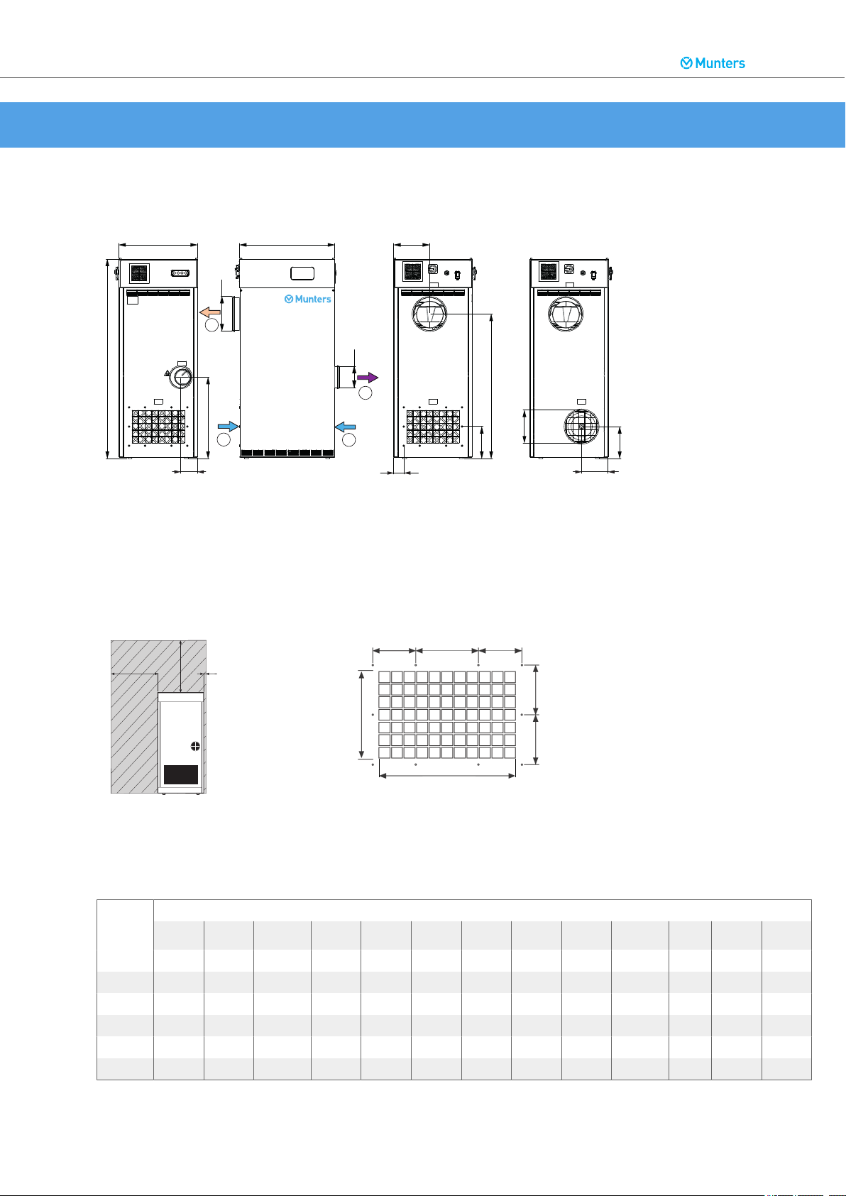
9.1. Dimensions and service space
Dimensions (IPI version to the right)
1. Process air
2. Dry air
3. Reactivation air
4. Wet air
Minimum required service space and screw pattern for duct connection
X=700 mm, Y=500 mm, Z=100 mm
ML /
MLT
420 720 600 1310 160 100 200 111 615 271 892 76 242 391
690 720 600 1410 200 125 200 112 615 272 992 76 242 201
800 720 600 1310 160 100 200 111 615 271 892 76 242 201
1100 720 600 1510 250 160 250 126 615 271 1092 76 242 201
1350 720 600 1510 250 160 250 126 615 271 1092 76 242 201
1400 720 600 1410 200 125 250 112 615 272 992 76 242 201
26
Dimensions (mm)
A B C ØD ØE ØF G H J L M P R
Page 27

5.0
1.0
2.0
3.0
4.0
ML420
5
10
15
20
25
80%
60%
40%
5.0
1.0
2.0
3.0
4.0
MLT800
5
10
15
20
25
80%
60%
40%
12.5
2.5
5.0
7.5
10.0
kg/h
15.0
ML690
0 5
10
15
20
25
80%
60%
40%
12.5
2.5
5.0
7.5
10.0
kg/h
15.0
ML1100
0 5
10
15
20
25
80%
60%
40%
Dehumidifier ML420-1350, MLT800-1400
9.2. Capacity diagrams
Approximate capacity in kg/h. Contact Munters for more detailed information.
NOTE
The below figures are based on rated airflow.
1. Process air temperature (°C)
2. Process air relative humidity (% RH)
3. Dehumidification capacity (moisture removal per hour) (kg/h)
27
Page 28

12.5
2.5
5.0
7.5
10.0
kg/h
15.0
ML1350
0 5
10
15
20
25
80%
60%
40%
12.5
2.5
5.0
7.5
10.0
kg/h
15.0
MLT1400
0 5
10
15
20
25
80%
60%
40%
Dehumidifier ML420-1350, MLT800-1400
28
Page 29

Dehumidifier ML420-1350, MLT800-1400
9.3. Technical data
Model ML420 ML690 MLT800 ML1100 ML1350 MLT1400
Process air
Rated airflow (m3/s) 0,116 0,192 0,222 0,305 0,375 0,388
Rated airflow (m3/h) 420 690 800 1100 1350 1400
Available static pressure (Pa)
Fan motor power (kW) at 50
3
Hz
Fan motor power (kW) at 60
3
Hz
Reactivation air
Rated airflow (m3/s) 0,043 0,071 0,043 0,113 0,136 0,071
Rated airflow (m3/h) 155 254 155 408 490 254
Available static pressure (Pa)
Fan motor power (kW) at 50
3
Hz
Fan motor power (kW) at 60
3
Hz
Rated current (amps/phase)
3~ 200 V 15 25 18 - - 27
3~ 220 V 14 23 16 - - 25
3~ 230 V 13 23 16 - - 24
3~ 380 V 8 14 10 22 26 15
3~ 400 V 8 13 9 21 25 14
3~ 415 V 8 13 9 20 25 14
3~ 440 V 7 12 9 19 23 13
3~ 460 V 7 12 9 19 22 13
3~ 480 V 7 12 8 18 21 13
Reactivation heater
Temp. increase across heater
(°C)
Reactivation heater power
(kW)
Miscellaneous data
Filters (standard) G4
IEC protection class (unit) IP33
IEC protection class (electrical
panel)
Fan motor winding insulation
class
Drive motor winding insulation
class
High temperature cut-out (°C) 160 ± 5
Contactor coil voltage (V AC) 24
External (potential-free) output
contacts
Corrosion class, outside casing C4 (painted, AluZink 150, ISO 12944)
1
2
200 300 200 300 300 300
0,37 0,55 0,55 1,1 1,1 1,1
0,37 0,56 0,66 1,32 1,32 1,32
1
2
200 300 200 300 300 300
- 0,37 0,37 0,55 0,55 0,37
- 0,44 0,44 0,66 0,66 0,44
95 95 95 95 95 95
4,2 6,9 4,2 11,1 13,5 6,9
IP54
Class F
Class F
2 A, 230 V AC (max.)
4
29
Page 30

Dehumidifier ML420-1350, MLT800-1400
Model ML420 ML690 MLT800 ML1100 ML1350 MLT1400
Corrosion class, inside casing C3 (unpainted, AluZink 150, ISO 12944)
Weight (kg) 141 159 141 169 169 159
Environmental conditions
Operating temperature (°C) -20... +40
Maximum installation altitude,
above sea level (m)
Transport and storage temperature (°C)
1
Figures quoted are based on fan inlet temperature of 20°C, and an air density of 1,2 kg/m3.
2
Without optional F5 or F7 filter boxes.
3
ML420 dehumidifiers have a single motor driving both process air and reactivation air fans.
4
Contacts used to give an external indication (output).
2000
-20... +70
9.4. Sound data
9.4.1. Definition
Duct connections
1. Ductwork for dry air
2. Ductwork for process air
3. Ductwork for reactivation air
4. Ductwork for wet air
Values
Lp(A) = Sound pressure (free field, Directivity factor Q=2, d=1 distance from source in meter)
Lp(A) = Lw(A) + 10Log(Q/(4πd²))
Lw(A) = Sound power level dB (A-weighted)
30
Page 31

Dehumidifier ML420-1350, MLT800-1400
9.4.2. Sound data ML420
Table 1. Sound to room, all inlets and outlets ducted
Lp(A) at
1 m
Hz 63 125 250 500 1000 2000 4000 8000
dB(A) 58 66 72 72 65 60 57 60 55 54
Lw(A) Measure range
Table 2. Sound in ducts
Duct Lw(A) Measure range
Hz 63 125 250 500 1000 2000 4000 8000
dB(A) 1. 68 88 79 68 61 57 53 48 41
2. 71 93 80 72 59 59 59 52 50
3. 76 93 84 80 73 64 57 54 48
4. 73 95 83 76 57 48 43 40 27
9.4.3. Sound data ML690
Table 3. Sound to room, all inlets and outlets ducted
Lp(A) at
1 m
Hz 63 125 250 500 1000 2000 4000 8000
dB(A) 60 68 72 76 69 64 62 58 55 51
Lw(A) Measure range
Table 4. Sound in ducts
Duct Lw(A) Measure range
Hz 63 125 250 500 1000 2000 4000 8000
dB(A) 1. 69 89 75 72 64 58 56 47 39
2. 73 91 83 78 64 61 62 59 54
3. 76 93 83 79 71 68 62 58 51
4. 71 93 83 73 59 50 46 39 24
31
Page 32

Dehumidifier ML420-1350, MLT800-1400
9.4.4. Sound data MLT800
Table 5. Sound to room, all inlets and outlets ducted
Lp(A) at
1 m
Hz 63 125 250 500 1000 2000 4000 8000
dB(A) 59 67 75 75 68 64 59 58 58 57
Lw(A) Measure range
Table 6. Sound in ducts
Duct Lw(A) Measure range
Hz 63 125 250 500 1000 2000 4000 8000
dB(A) 1. 71 84 78 75 68 60 60 54 48
2. 75 90 86 78 66 63 65 62 59
3. 76 93 84 80 73 64 57 54 48
4. 73 95 83 76 57 48 43 40 27
9.4.5. Sound data ML1100
Table 7. Sound to room, all inlets and outlets ducted
Lp(A) at
1 m
Hz 63 125 250 500 1000 2000 4000 8000
dB(A) 64 72 75 81 73 68 65 63 58 56
Lw(A) Measure range
Table 8. Sound in ducts
Duct Lw(A) Measure range
Hz 63 125 250 500 1000 2000 4000 8000
dB(A) 1. 77 89 88 81 71 64 62 53 45
2. 79 89 87 80 69 71 72 69 64
3. 84 93 91 87 81 76 70 68 63
4. 79 96 92 83 69 58 54 48 40
32
Page 33

Dehumidifier ML420-1350, MLT800-1400
9.4.6. Sound data ML1350
Table 9. Sound to room, all inlets and outlets ducted
Lp(A) at
1 m
Hz 63 125 250 500 1000 2000 4000 8000
dB(A) 67 75 77 83 74 72 68 66 61 59
Lw(A) Measure range
Table 10. Sound in ducts
Duct Lw(A) Measure range
Hz 63 125 250 500 1000 2000 4000 8000
dB(A) 1. 80 93 89 84 77 68 66 56 46
2. 80 88 86 81 72 72 74 68 60
3. 83 93 89 85 81 77 71 67 62
4. 75 92 87 78 70 62 56 52 43
9.4.7. Sound data MLT1400
Table 11. Sound to room, all inlets and outlets ducted
Lp(A) at
1 m
Hz 63 125 250 500 1000 2000 4000 8000
dB(A) 63 71 74 80 73 67 63 63 58 56
Lw(A) Measure range
Table 12. Sound in ducts
Duct Lw(A) Measure range
Hz 63 125 250 500 1000 2000 4000 8000
dB(A) 1. 78 91 84 81 74 68 72 60 55
2. 82 85 87 82 73 73 77 71 66
3. 76 89 83 79 72 69 63 60 52
4. 70 93 80 71 58 49 48 41 30
33
Page 34

Dehumidifier ML420-1350, MLT800-1400
10. Disposal
The unit and consumables must be disposed of in accordance with applicable legal requirements and
regulations. Contact your local authorities.
If the rotor or filters have been exposed to chemicals that are dangerous to the environment the risk
must be assessed. The chemicals can accumulate in the material. Take the necessary precautions to
comply with applicable local legal requirements and regulations.
The rotor material is not combustible, and should be deposited like fiberglass materials.
WARNING
If the rotor is to be cut in pieces, wear a suitable CE marked face mask selected and
fitted in accordance with the applicable safety standards to protect from the dust.
34
Page 35

Dehumidifier ML420-1350, MLT800-1400
11. Contact Munters
EUROPE
AUSTRIA Tel: +43 1 616 4298-92 51
ITALY Tel: +39 0183 521377
luftentfeuchtung@munters.at
BELGIUM Tel: +3215285611
service@muntersbelgium.be
CZECH REPUBLIC
DENMARK Tel: +4544953355
FINLAND Tel: +358 207 768 230
FRANCE Tel: +33 1 34 11 57 57
GERMANY Tel: +49 (0) 40 879 690 - 0
WORLDWIDE
AUSTRALIA Tel:+61 288431588
Tel: +420 775 569 657
info@munters-odvlhcovani.cz
info@munters.dk
laitemyynti@munters.fi
dh@munters.fr
mgd@munters.de
marketing@munters.it
NETHERLANDS
POLAND Tel.: + 48 58 305 35 17
SPAIN Tel: +34 91 640 09 02
SWEDEN Tel: +46 8 626 63 00
SWITZERLAND Tel: +41 52 343 88 86
UK Tel: +44 1480 432 243
MEXICO Tel:+52 722 270 40 29
Tel: +31 172 43 32 31
vochtbeheersing@munters.nl
dh@munters.pl
marketing@munters.es
kundservice.avfuktning@munters.se
info.dh@munters.ch
info@munters.co.uk
dh.info@munters.com.au
BRAZIL Tel: +55 41 3317 5050
www.munters.com.br
CANADA Tel: +1-800-843-5360
dhinfo@munters.com
CHINA Tel: +86 10 804 18000
marketing@munters.cn
INDIA Tel:+91 20 668 18 900
info@munters.in
JAPAN Tel:+81 3 5970 0021
mkk@munters.jp
KOREA Tel:+82 2 761 8701
munters@munters.kr
munters@munters.com.mx
SINGAPORE Tel:+65 6744 6828
singapore@muntersasia.com
SOUTH AFRICA
TURKEY Tel:+90 216 548 14 44
UAE (Dubai) Tel:+971 4 881 3026
USA Tel: +1-800-843-5360
Tel:+27 11 997 2000
info@munters.co.za
info@muntersform.com
middle.east@munters.com
dhinfo@munters.com
35
Page 36

www.munters.com
 Loading...