

Page 1
Originalinstructions
Usermanual
ML420,ML690,MLT800
ML1100,ML1350,MLT1400
Desiccantdehumidier
190TGB-1035-H1604©MuntersEuropeAB2016
Page 2

Importantuserinformation
Intendeduse
Muntersdehumidiersareintendedtobeusedforthe
dehumidicationofair.Anyotheruseoftheunit,or
usewhichiscontrarytotheinstructionsgiveninthis
manual,cancausepersonalinjuryanddamagetotheunit
andotherproperty.
Nomodicationoftheunitisallowedwithoutprior
approvalbyMunters.Attachmentorinstallation
ofadditionaldevicesisonlyallowedafterwritten
agreementbyMunters.
Warranty
Thewarrantyperiodisvalidfromthedatetheunit
leftourfactory,unlessotherwisestatedinwriting.
Thewarrantyislimitedtoafreeexchangeofpartsor
componentswhichhavefailedasaresultofdefectsin
materialsorworkmanship.
Allwarrantyclaimsmustincludeproofthatthe
faulthasoccurredwithinthewarrantyperiodand
thattheunithasbeenusedinaccordancewiththe
specications.Allclaimsmustspecifytheunittypeand
fabricationnumber.Thisinformationisstampedonthe
identicationplate,seesectionMarking.
Itisaconditionofthewarrantythattheunitforthefull
warrantyperiodisservicedandmaintainedbyaqualied
MuntersengineerorMuntersapprovedengineer.
Accesstospecicandcalibratedtestequipmentis
necessary.Theserviceandmaintenancemustbe
documentedforthewarrantytobevalid.
AlwayscontactMuntersforserviceorrepair.Operating
faultscanoccuriftheunitismaintainedinsufcientlyor
incorrectly.
Safety
Informationaboutdangersareinthismanualindicated
bythecommonhazardsymbol:
W
ARNING!
W W
ARNING! ARNING!
Indicatesapossibledangerthatcanleadtopersonalinjury .
CA
UTION!
CA CA
UTION! UTION!
Indicatesapossibledangerthatcanleadtodamagetothe
unitorotherproperty ,orcauseenvironmentaldamage.
NOTE!Highlightssupplementaryinformationforoptimal
useoftheunit.
ConformitywithDirectives
Thedehumidierisinconformitywiththeessential
safetyrequirementsoftheMachineryDirective
2006/42/EC,andinconformitywiththeprovisionsof
theEcodesignDirective(ErP)2009/125/EC,andof
theEMCDirective2004/108/EC.Thedehumidieris
manufacturedbyanorganizationcertiedaccordingto
ISO9001andISO14001.
Copyright
Thecontentsofthismanualcanbechangedwithout
priornotice.
NOTE!Thismanualcontainsinformationwhichis
protectedbycopyrightlaws.Itisnotallowedtoreproduceor
transmitanypartofthismanualwithoutwrittenconsentfrom
Munters.
Pleasesendanycommentsregardingthismanualto:
MuntersEuropeAB
TechnicalDocumentation
P.O.Box1150
SE-16426KISTASweden
e-mail:t-doc@munters.se
iiImportantuserinformation190TGB-1035-H1604
Page 3

Tableofcontents
Importantuserinformation...............ii
Intendeduse...........................
Warranty...............................
Safety..................................
ConformitywithDirectives............
Copyright..............................
Tableofcontents...........................iii
1Introduction.................................1
1.1Aboutthismanual.....................
1.2Unintendeduse........................
1.3Safetyandcautions...................
1.4Markings...............................
1.5Supervisionofoperation..............
1.6Faultindications.......................
2Dehumidierdesign.......................4
2.1Productdescription...................
2.2Functiondescription..................
2.3Maincomponents.....................
3Transport,inspectionandstorage.......6
3.1Transport..............................
3.2Inspectionofdelivery..................
3.3Storingtheequipment................
4Installation...................................7
4.1Safety..................................
4.2Siterequirements.....................
4.3Foundation............................
4.4Mirrorhandedductconnections......
4.5Ductinstallation.......................
4.5.1Generalrecommendations...
4.5.2Ductforoutdoorairinlet.......
4.5.3Ductforwetairoutlet...........
4.6Precautionarymeasuresforunitswith
LIdesiccantrotor......................
4.7Electricalconnections................
4.8Externalhumiditysensor.............
4.9Gasreactivation(ML1100units
only)....................................
5Commissioning.............................15
5.1Settingsbeforestart-up...............
5.1.1Continuousprocessairfan
operation.......................
5.1.2Single-stagehumiditysensor.
ii
ii
ii
ii
6Operation....................................18
ii
1
1
1
3
3
3
4
4
5
6
6
6
7
7
8
8
9
9
12
12
13
13
13
14
15
15
7Serviceandmaintenance.................24
8Faulttracing.................................28
9Technicalspecication....................31
10Scrapping....................................40
5.1.3Two-stagehumiditysensor...
5.1.4Remotefaultindication........
5.2Pre-startchecks.......................
5.3Airowcheckandadjustment........
6.1General................................
6.2Quickstop..............................
6.3Beforestarting.........................
6.4Operatorpanel........................
6.5RH98operatorpanel..................
6.6Operatingtheunit.....................
6.6.1Manualmode..................
6.6.2Automaticmode–humidity
sensorconnected..............
6.6.3Automaticmode-RH98or
VariDry(option)................
7.1Safety..................................
7.2General................................
7.3Serviceoptions........................
7.4Extendedwarranty....................
7.5Cleaning...............................
7.6Serviceandmaintenanceschedule..
7.7Filterchange...........................
8.1General................................
8.2Safety..................................
8.3Faulttracinglist........................
9.1Dimensionsandservicespace.......
9.2Capacitydiagrams....................
9.3Technicaldata.........................
9.4Sounddata.............................
9.4.1SounddataML420............
9.4.2SounddataML690............
9.4.3SounddataMLT800...........
9.4.4SounddataML1100...........
9.4.5SounddataML1350...........
9.4.6SounddataMLT1400..........
15
15
15
16
17
18
18
18
19
21
21
21
22
22
24
24
24
25
25
25
27
28
28
29
31
32
34
36
36
37
37
38
38
39
190TGB-1035-H1604Tableofcontentsiii
Page 4

Appendix1Options.............................41
1.1General................................
1.2Runningtimemeter...................
1.3Rotorstopalarm.......................
1.4Blockedlteralarm....................
1.5Filterbox-M5andF7..................
1.6Humiditycontrolsystem..............
1.6.1Introduction....................
1.6.2Transmitter.....................
1.6.3Controlunit.....................
41
41
41
41
41
42
42
42
2ContactMunters............................49
1.6.4Setpointsandcontrol
parameters.....................
1.6.5Display/changesetpointfor
relativehumidity...............
1.6.6Display/changeother
parameters.....................
1.6.7Processalarms................
42
43
44
44
47
ivTableofcontents190TGB-1035-H1604
Page 5

DehumidierML420-MLT1400
1Introduction
1.1Aboutthismanual
Thismanualiswrittenfortheuserofthedehumidier.Itcontainsnecessaryinformationforhowtoinstall
andusethedehumidierinasafeandefcientway.Readthroughthemanualbeforethedehumidieris
installedandused.
ContactyournearestMuntersofceifyouhaveanyquestionsregardingtheinstallationortheuseofyour
dehumidier.
Thismanualmustbestoredinapermanentlocationclosetothedehumidier.
1.2Unintendeduse
■Thedehumidierisnotintendedforoutdoorinstallation.
■Thedehumidierisnotintendedforuseinclassiedareaswhereexplosionsafetycompliantequipment
isrequired.
■Thedehumidiermustnotbeinstallednearanyheatgeneratingdevicesthatcancausedamagetothe
equipment.
1.3Safetyandcautions
Everymeasurehasbeentakeninthedesignandmanufactureofthedehumidiertoensurethatitmeetsthe
safetyrequirementsofthedirectivesandstandardslistedintheECDeclarationofConformity.
Theinformationinthismanualshallinnowaytakeprecedenceoverindividualresponsibilitiesorlocal
regulations.
Duringoperationandotherworkwithamachineitisalwaystheresponsibilityoftheindividualtoconsider
thefollowing:
■Thesafetyofallpersonsconcerned.
■Thesafetyoftheunitandotherproperty.
■Theprotectionoftheenvironment.
ThetypesofdangersthatareindicatedinthismanualaredescribedinthesectionImportantuserinformation.
190TGB-1035-H1604Introduction1
Page 6

DehumidierML420-MLT1400
W
ARNING!
W W
ARNING! ARNING!
-Theunitmustnotbesplashedwithorimmersedinwater.
-Theunitmustneverbeconnectedtoavoltageorfrequencyotherthanthatforwhichitwasdesigned.Refertothe
identicationplate.Linevoltagethatistoohighcancauseanelectricalshockhazardanddamagetotheunit.
-Donotinsertngersoranyobjectsintotheairvents.
-Allelectricalinstallationsmustbecarriedoutbyaqualiedelectricianandinaccordancewithlocalregulations.
-Thedehumidiercanrestartautomaticallyafterapowercut.Alwayssetandlockthemainpowerswitchinthe
OFFpositionbeforecarryingoutanyservicework.
-Useonlyapprovedliftingequipmenttopreventpersonalinjuryanddamagetotheequipment.
-AlwayscontactMuntersforserviceorrepair.
2Introduction190TGB-1035-H1604
Page 7
DehumidierML420-MLT1400
Reg.luft
Reac.air
Reg.Luft
Air de regeneration
'''
Processluft
Process air
Prozessluft
Air a traiter
`
Våtluft
Wet air
Nassluft
Air humide
Torrluft
Dry air
Trockenluft
Air sec
3
1
4
5
2
3
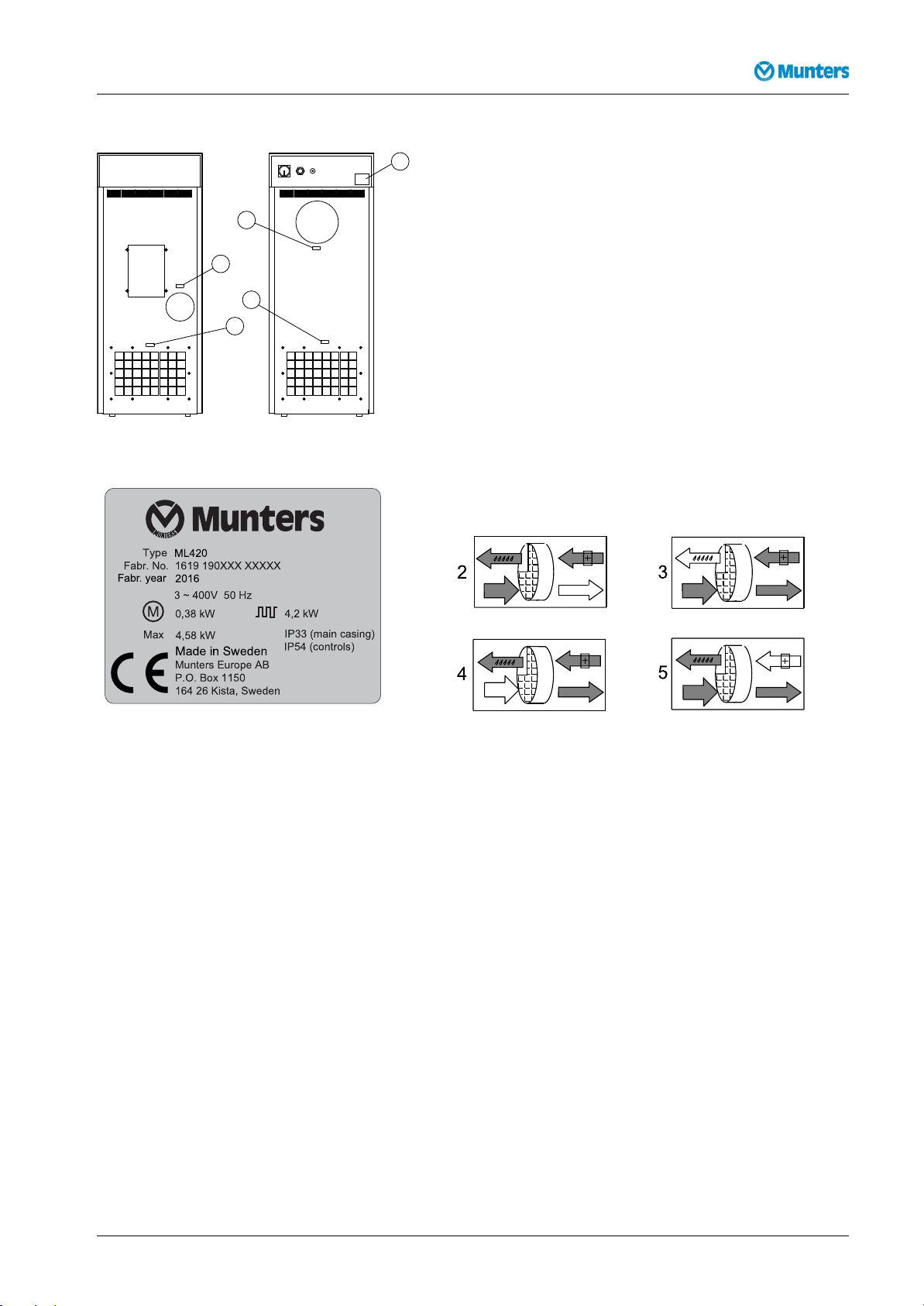
1.4Markings
Figure1.1Identicationplateandmarkings
Figure1.2Identicationplate,example
1.Unitidenticationplate
4.Processairinlet
Figure1.3Labelsforairinletsandoutlets
2.Dryairoutlet5.Reactivationairinlet
3.Wetairoutlet
Explanationof"Fabr.no"ontheidenticationplate:
09=yearofmanufacture,19=weekofmanufacture,190XXX=articlenumber,XXXXX=serialnumber
1.5Supervisionofoperation
Thedehumidieriscontrolledandmonitoredusingtheoperatorpanellocatedonthefrontoftheunit.
1.6Faultindications
Faultsareclearlyindicatedontheoperatorpanel,seesection6.4,Operatorpanel.
Alarmsrelatingtorelativeairhumidityaregiveninthedisplayofthehumiditycontrolsystem(ifinstalled),
seeappendix1.6,Humiditycontrolsystem.
190TGB-1035-H1604Introduction3
Page 8

DehumidierML420-MLT1400
2
4
3
1
2Dehumidierdesign
2.1Productdescription
ThedesiccantdehumidiersintheMLserieshavebeendevelopedtoeffectivelydehumidifytheairin
environmentsrequiringlowairhumidity.
Thedehumidierisequippedwithanencapsulatedrotorunit.Therotorcasingisconstructedofdurable
thermosetplasticandcontainsisolatedsectionsthatprovideaprecisebalanceforthedehumidication,
reactivationandheatrecoveryairows.
ThedehumidierismanufacturedinaccordancewithuniformEuropeanstandardsandestablished
requirementsforCE-marking.
2.2Functiondescription
1.Processair
2.Dryair
3.Reactivationair
4.Wetair
Figure2.1Internalairows
Thedesiccantrotoristheadsorptiondehumidifyingcomponentintheunit.Therotorstructureis
comprisedofalargenumberofsmallairchannels.
Thedesiccantrotorismadeofacompositematerialthatishighlyeffectiveinattractingandretainingwater
vapour.Therotorisdividedintwozones.Theairowtobedehumidied,processair,passesthroughthe
largestzoneoftherotorandthenleavestherotorasdryair.Sincetherotorrotatesslowly,theincomingair
alwaysmeetsadryzoneontherotor,thuscreatingacontinuousdehumidicationprocess.
Theairowthatisusedtodrytherotor,reactivationair,isheated.Thereactivationairpassesthrough
therotorintheoppositedirectiontotheprocessairandleavestherotoraswetair(warm,moistair).This
principleenablesthedehumidiertoworkeffectively ,evenatfreezingtemperatures.
4Dehumidierdesign190TGB-1035-H1604
Page 9
DehumidierML420-MLT1400
11
1
4
5
6
8
9
2
16
3
12
14
13
15
10
7
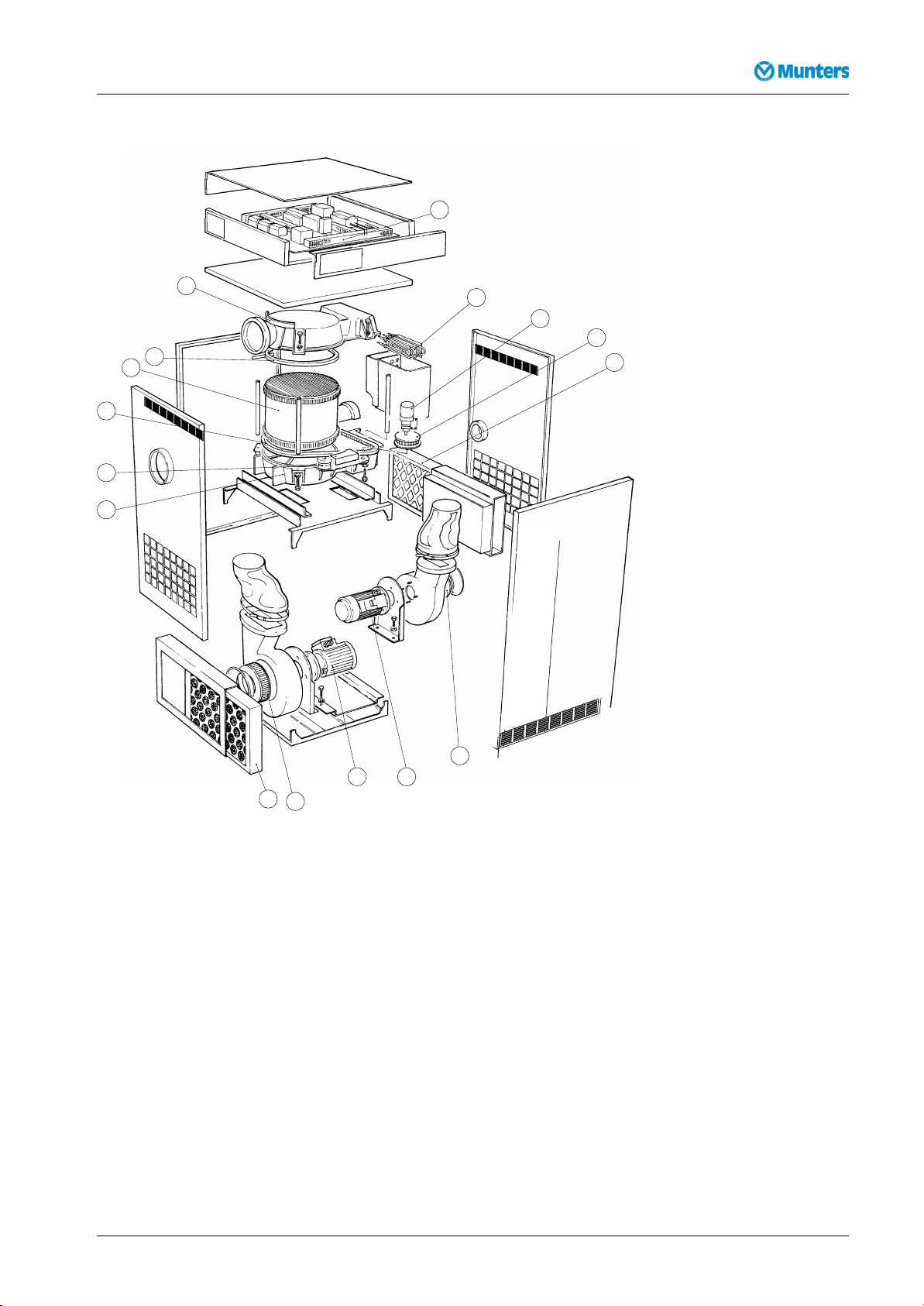
2.3Maincomponents
Figure2.2Maincomponents
1.Lowerrotorcover9.Drivemotor
2.Roller,beltguide10.Pulley,beltdrive
3.Drivebelt11.
4.Rotor12.Reactivationairimpeller
5.
Sealingring,rotor
6.Upperrotorcover14.
7.
Electricalcontrolpanel15.Processairimpeller
8.Reactivationheater16.
13.
Reactivationairlter
Reactivationfanmotor
Processfanmotor
Processairlter
NOTE!TheML420unithasonlyonefanmotorthatisplacedbetweentheprocessandreactivationimpeller.
190TGB-1035-H1604Dehumidierdesign5
Page 10
DehumidierML420-MLT1400
3Transport,inspectionandstorage
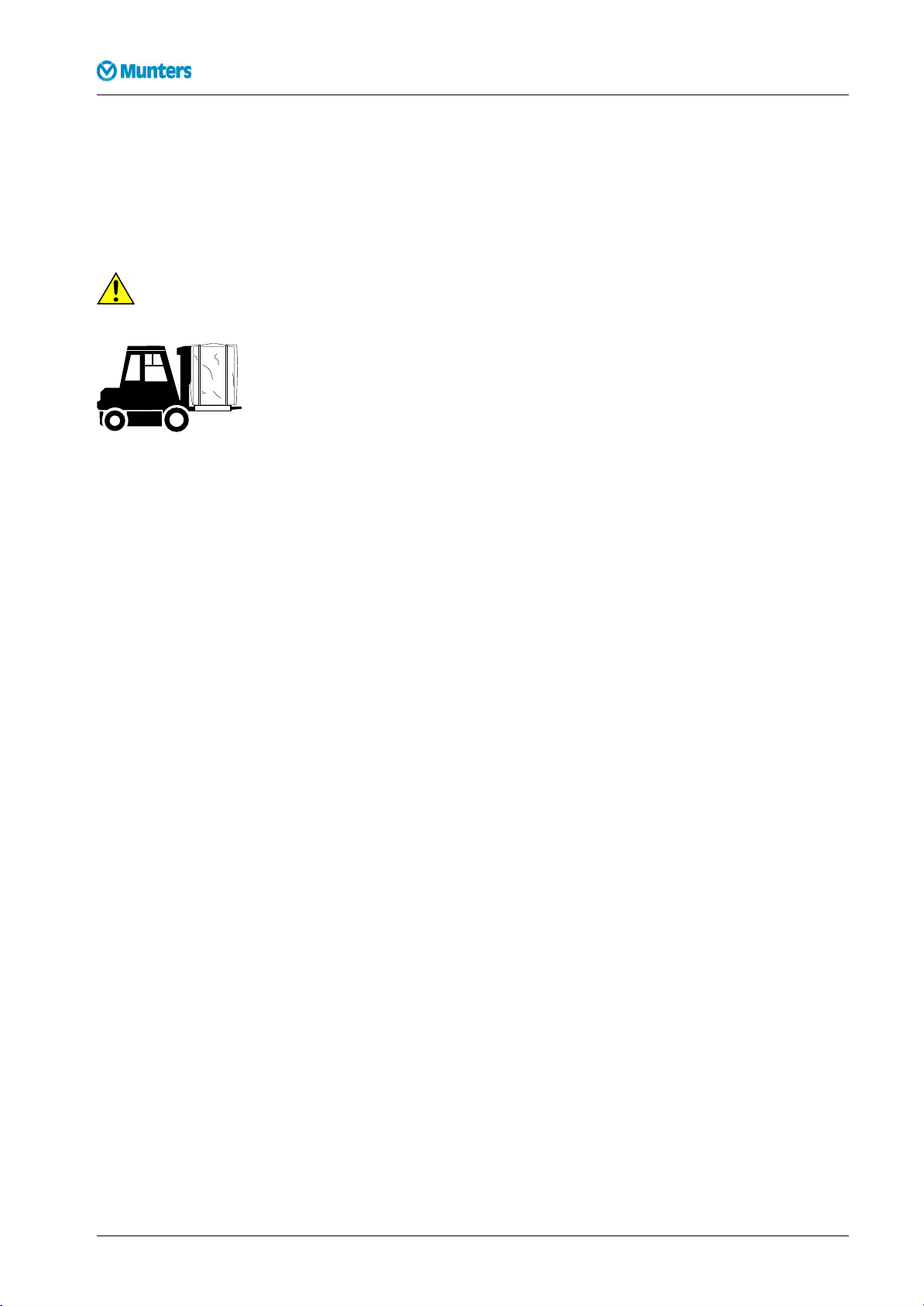
3.1Transport
Thedehumidierisdeliveredonapalletandmustbehandledcarefully .Allpaneldoorsontheunitmustbe
closedduringtransport.Providedthatthedehumidierisstillsecuredtoitsdeliverypallet,itcanbemoved
usingafork-lifttruck.
W
ARNING!
W W
ARNING! ARNING!
Movethedehumidiercarefullyasthereisariskofthedehumidiertippingover.
Figure3.1Correctlengthonforkliftarms
Weightofthedehumidiercanbefoundinsection9.1,Dimensionsandservicespace.
3.2Inspectionofdelivery
■Doaninspectionofthedeliveryandcomparewiththedeliverynote,orderconrmationorother
deliverydocumentation.Makesurethateverythingisincludedandnothingisdamaged.
■ContactMuntersimmediatelyifthedeliveryisnotcompleteordamagedinordertoavoidinstallation
delays.
■Removeallpackagingmaterialfromtheunit,andmakesurethatnodamagehasbeenmadeduring
transportation.
■AnyvisibledamagemustbereportedinwritingtoMunterswithin3daysandpriortoinstallationof
theunit.
■Discardthepackagingmaterialaccordingtolocalregulations.
3.3Storingtheequipment
Followtheseinstructionsifthedehumidieristobestoredpriortoinstallation:
■Placethedehumidierinanuprightpositiononahorizontalsurface.
■Re-usethepackagingmaterialtoprovideprotectionfortheunit.
■Protectthedehumidierfromphysicaldamage.
■Storethedehumidierundercoverandprotectitfromdust,frost,rainandaggressivecontaminants.
6Transport,inspectionandstorage190TGB-1035-H1604
Page 11

DehumidierML420-MLT1400
4Installation
4.1Safety
W
ARNING!
W W
ARNING! ARNING!
-Theunitmustnotbesplashedwithorimmersedinwater.
-Theunitmustneverbeconnectedtoavoltageorfrequencyotherthanthatforwhichitwasdesigned.Refertothe
identicationplate.Linevoltagethatistoohighcancauseanelectricalshockhazardanddamagetotheunit.
-Donotinsertngersoranyobjectsintotheairvents.
-Allelectricalinstallationsmustbecarriedoutbyaqualiedelectricianandinaccordancewithlocalregulations.
-Thedehumidiercanrestartautomaticallyafterapowercut.Alwayssetandlockthemainpowerswitchinthe
OFFpositionbeforecarryingoutanyservicework.
-Useonlyapprovedliftingequipmenttopreventpersonalinjuryanddamagetotheequipment.
-AlwayscontactMuntersforserviceorrepair.
CA
UTION!
CA CA
UTION! UTION!
Thewetairductmustalwaysbeinsulatedwhenthereisariskoffreezing.Condensationbuildsupeasilyonthe
insideoftheductbecauseofthehighmoisturecontentofthewetairleavingthedehumidier.
CA
UTION!
CA CA
UTION! UTION!
Thedehumidierhasbeendesignedtooperateatspecicprocessairowscorrespondingtothefansizes
installed.
4.2Siterequirements
Thedehumidierisonlyintendedforindoorinstallation.Avoidinstallingthedehumidierinadamp
environmentwherethereisariskofwaterenteringtheunitorinaverydustyenvironment.Ifindoubt,
contactMunters.Itisimportantthattheintendedinstallationsitemeetsthelocationandspacerequirements
fortheequipmentinordertoachievethebestpossibleperformance.
Fortheunitdimensionsandservicespacerequirements,seesection9.1,Dimensionsandservicespace.
NOTE!Ifthereisaneedforreductionofvibrationsfromthedehumidier,contactMuntersforinstructions.
190TGB-1035-H1604Installation7
Page 12
DehumidierML420-MLT1400
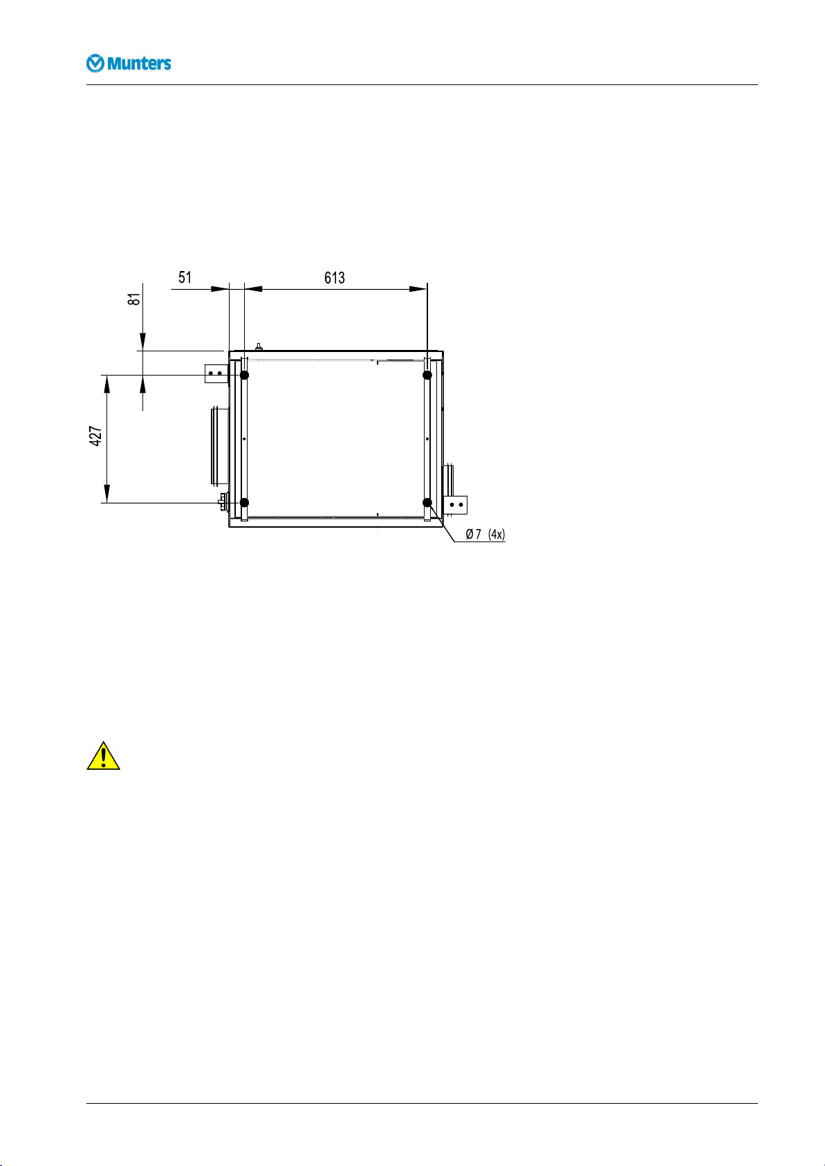
4.3Foundation
Thedehumidiermustbeinstalledonaleveloor,oronaplatformcapableofsupportingthemachine
weight.Ifthemaximumoorloadingweightisnotexceeded,specialfoundationsarenotrequired.
Whenthedehumidierhasbeeninstalled,checkthatitislevel.
Iflocalregulationsrequirethattheunitispermanentlyxedinposition,thexingholescanbeusedfor
boltingtheunittotheoor.
Figure4.1Drillingpattern
4.4Mirrorhandedductconnections
Thefrontandrearpanelsareinterchangeable,sothattheconnectionsforprocessairanddryairmaybe
situatedeitherontheleftorrightsideoftheunit.
Thedehumidiersaredeliveredwiththeprocessanddryairconnectionsontheleftsideoftheunit.If
itisrequiredtochangetheorientation,sothattheconnectionsareontherightsideoftheunit,proceed
asfollows.
W
ARNING!
W W
ARNING! ARNING!
Makesurethatthedehumidierisdisconnectedfromthemainspowerbeforechangingthepositionsofthe
processairanddryairconnections.
8Installation190TGB-1035-H1604
Page 13
DehumidierML420-MLT1400
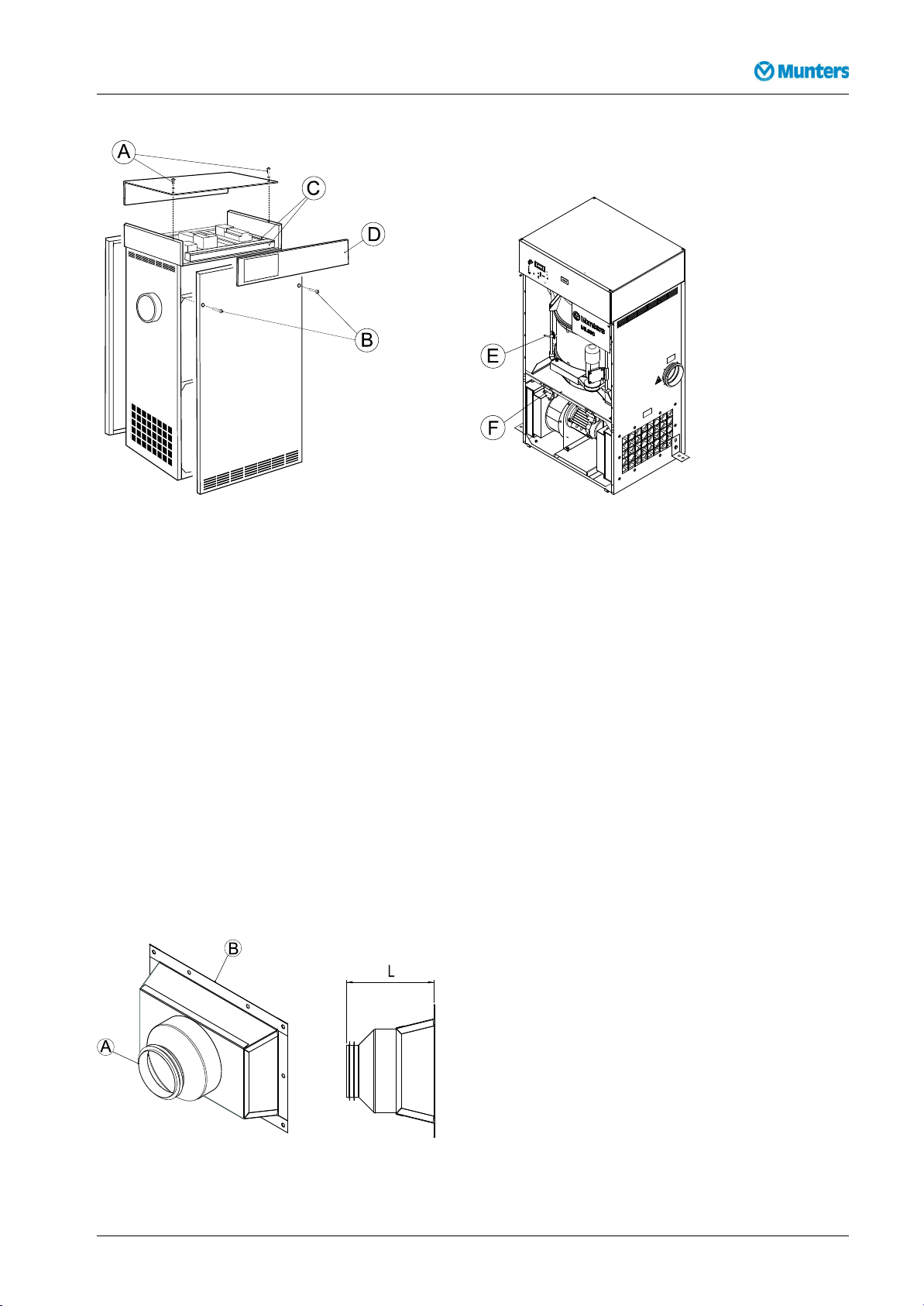
Figure4.2ChangingpanelpositionsFigure4.3Rotorstop(E)andltermonitors(F)
1.Removethetwobolts(B)securingthefrontpanelandcarefullyremovethepanel.
2.Removethetwoboltssecuringtherearpanelandcarefullyremovethepanel.
3.Removethetwobolts(A)andwasherssecuringthecontrolandtoppanels,thencarefullyremovethe
toppanel.
4.Removethecableductcovers(C),re-routethecablesandtthecontrolpanel(D)ontotheoppositeside
oftheunit.Retthecableductcovers.
5.Loosentherotorstop(E)andthetwoltermonitors(F).Removethecableties.
6.Fittherotorstopandltermonitorsontheoppositesideoftheunit.Tiethecables.
7.Fitthefront,rearandtoppanelsintheirnewpositions.
4.5Ductinstallation
4.5.1Generalrecommendations
Theconnectionsforprocessandreactivationairaredesignedinaccordancewiththerecommendationsin
ISO13351.TherectangularductconnectionscontaintappedinsertsforM8screws.
Figure4.4Ductconnections
190TGB-1035-H1604Installation9
Page 14

DehumidierML420-MLT1400
Partnumber170-013448–005170-013448–004170-013448–003170-013448–002170-013448–001
A
B
L(mm)
ML420XX
ML690XX
MLT800XX
ML1100XX
ML1350XX
MLT1400XX
CA
UTION!
CA CA
UTION! UTION!
Ø100Ø125Ø160Ø200Ø250
Seesection9.1,Dimensionsandservicespace.
210210200140150
Thedehumidierhasbeendesignedtooperateatspecicprocessairowscorrespondingtothefansizes
installed.
■Theprocessairanddryairductsshouldbethesamediameter.Thesameappliestothereactivationair
andwetairducts.
■Thelengthofductworkmustbekeptasshortaspossibletominimisestaticairpressurelosses.
■Tomaintainperformance,allrigidprocessorreactivationairductworkjointsmustbeairandvapour
tight.
■Theprocessairductworkmustbeinsulatedtopreventcondensationdevelopingontheoutsideofthe
duct,wheneverthetemperatureoftheairwithintheductfallsbelowthedewpointtemperatureofthe
ambientairthroughwhichtheductworkisrouted.
■Theductsmustalwaysbeinsulatedwhenthereisariskoffreezing.
■Thewetairleavingthedehumidierwill,becauseofhighmoisturecontent,condenseontheinsideduct
walls.Byinsulatingtheducts,theamountofcondensateisreduced.
■Horizontalwetairductsmustbeinstalledwithaslightdecline(awayfromthedehumidier)todrain
awaypossiblecondensation.Suitablecondensationdrainsmustbeinstalledatlowpointsinthewet
airoutletduct,seeFigure4.7.
■Ensurethataccessforoperationandservicingisnotrestrictedwhendesigningandinstallingducting.
Formoreinformation,refertosection9.1,Dimensionsandservicespace.
■Toreducenoiseand/orvibrationbeingtransmittedalongrigidducts,goodquality,airtightexible
connectionscanbetted.
■Ductsmounteddirectlyontotheunitmustbeindependentlysupportedtominimisetheloadontheunit.
■Dampersforadjustingtheairowsmustbeinstalledinthesupplyairoutletandreactivationairinlet
ducts.Correctairowsareessentialfortheoperatingefciencyoftheunit.Forairowadjustment
instructions,seesection5.3,Airowcheckandadjustment.
■Thetotalpressuredropintheprocessandreactivationductworkmustnotexceedtheavailablepressure
ofthefansttedtothedehumidier.Fordetailsofminimumavailablestaticpressure,seesection
9.3,Technicaldata.
10Installation190TGB-1035-H1604
Page 15

DehumidierML420-MLT1400
ML
Munter s
420
1
2
3
5
5
4
C
B
D
A
Figure4.5Ductsrequiredforinstallation
A.Processairinlet1.Dryairdamper
B.Dryairoutlet
C.Reactivationairinlet
D.Wetairoutlet4.Reactivationairdamper
2.Externallterbox(option)
3.Ducttransition
5.Outlet/inletduct(wirenetting)
190TGB-1035-H1604Installation11
Page 16
DehumidierML420-MLT1400
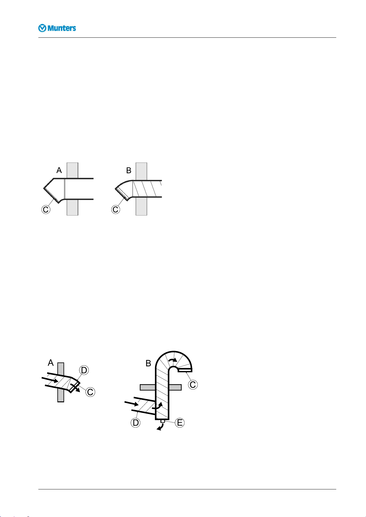
4.5.2Ductforoutdoorairinlet
Whenbringingambientairfromoutdoorsintothedehumidier,theinletductopeningmustbelocated
sufcientlyhighabovegroundleveltopreventdustanddebrisfromentering.
Theductingmustbedesignedtopreventrainandsnowfrombeingdrawnintothedehumidier.Theair
inletmustbelocatedawayfrompossiblecontaminantssuchasengineexhaustgases,steamandharmful
vapours.
Topreventthewet(outlet)airfromhumidifyingthereactivation(inlet)air,theairinletforreactivationmust
belocatedatleast2mfromthewetairoutlet.
Attachawirenetwithameshwidthofapproximately10mmintheouterendoftheducttopreventanimals
fromenteringthedehumidierducting.
A.Rectangularducting
B.Roundducting
C.Wirenetting
Figure4.6Outdoorairinletdesign
4.5.3Ductforwetairoutlet
Thematerialforthewetairductmustwithstandcorrosionandtemperaturesofupto100°C.Thewetair
ductingmustalwaysbeinsulatedifthereisariskofcondensation.Thewetairleavingthedehumidierwill
easilycausecondensationontheinsideoftheductwallsduetothehighmoisturecontent.
Horizontalductsmustbeinstalledslopingdownwards(awayfromthedehumidier)todrainawaypossible
condensation.Theductslopemustbeatleast2cm/m.Inaddition,drainageholes(5mm)shouldbemadeat
lowpointsintheducttopreventwateraccumulation.
Attachawirenetwithameshwidthofapproximately10mmintheouterendoftheducttopreventanimals
fromenteringthedehumidierducting.
A.Horizontalwetairoutlet
B.Verticalwetairoutlet
C.Wirenetting
D.Downwardslope
E.Condensatedrainage
Figure4.7Wetairoutletdesign
12Installation190TGB-1035-H1604
Page 17

DehumidierML420-MLT1400
4.6PrecautionarymeasuresforunitswithLIdesiccantrotor
ThestandarddeliveryisMuntershighperformancedesiccantrotorHPS(HighPerformanceSilicagel).
IfthedehumidierisdeliveredwithanLIrotor(lithiumchloride)itisimportantthattherotordoesnot
becomeloadedwithmoisturewhenthedehumidierisoff.
NOTE!Makesurethatnoairpassingthroughtherotorhasarelativehumiditygreaterthan80%.
Itisrecommendedtoinstallclosingdampersintheprocessandreactivationairinletstoavoidthatairwith
highrelativehumidityisdrawnthroughtherotorandintotheroom.
Thisisparticularlyimportantwhentheprocessairisdrawnfromoutdoors,orwhenthesystemhasbeen
ttedwithapre-cooler.
4.7Electricalconnections
W
ARNING!
W W
ARNING! ARNING!
Allelectricalequipmentconnectionsmustbecarriedoutinaccordancewithlocalregulationsandbyqualied
personnel.Riskofelectricalshock.
W
ARNING!
W W
ARNING! ARNING!
Theunitmustneverbeconnectedtoavoltageorfrequencyotherthanthatforwhichitwasdesigned.Refertothe
unitidenticationplate.
Eachunitissuppliedcompletewithalltheinternalwiringinstalledandconguredinaccordancewiththe
speciedvoltageandfrequencyontheidenticationplate.
NOTE!Thesupplyvoltagemustnotdifferfromthespeciedoperatingvoltagebymorethan+/-10%.
Forconnectiondetails,seetheidenticationplateandthewiringdiagramorsection9.3,Technicaldata.
4.8Externalhumiditysensor
ML-seriesdehumidiersarewiredsothatwhentheunitissettoAUTOmatic,itcanbecontrolledfrom
anexternallymountedhumiditysensor.
Allmodelshaveatwo-stageheater,andcanbecontrolledbyatwo-stagehumiditysensor.Thismethodis
moreefcientandallowsformoreaccuratedehumidicationcontrol.
Theelectricalconnectionsaremadeatterminalsintheelectricalcontrolpanel.Forwiringandconnection
details,seethewiringdiagram.
NOTE!Wherenohumiditysensorisconnectedtotheunit,thedehumidierwillbeoperatingatmaximumoutput
foraslongastheunitisswitchedon.
Aroomhumiditysensoristobemounted1-1.5mabovetheoor.Itmustbepositionedsothatitisnot
directlyexposedtodryairfromtheunitortohumidairowinginthroughopeningdoors.Positionitaway
fromheatsourcesanddirectsunlight.
■Thehumiditysensorconnectingcableshouldhaveaconductorareaofnotlessthan
0,75mm
■ThehumiditysensormustbedesignedsothatthecontactscloseonarisingRHtocompletethecontrol
2
andmusthaveaninsulationresistanceratinginexcessof500VAC.
circuitandstartthedehumidier.
190TGB-1035-H1604Installation13
Page 18

DehumidierML420-MLT1400
■Voltagedropscanoccurwhenusingexcessivelylongcables.
Ifthevoltageacrosstheterminalsusedforconnectingthehumiditysensorislessthan20VAC,aseparate
relaycontrolledbythehumiditysensormustbeused.
4.9Gasreactivation(ML1100unitsonly)
Forfurtherinformationoninstallation,start-upandmaintenanceofgasburners,seeappendixaboutgas
reactivationprovidedwiththeunit.
14Installation190TGB-1035-H1604
Page 19

DehumidierML420-MLT1400
5Commissioning
TheML420-MLT1400dehumidiershaveseveralstandardfunctionsthatneedtobesetbeforeinitial
start-up.Someofthefunctionsrequireconnectiontoexternalequipment.
Somefeaturesrequireconnectionofexternalequipment.Forwiringdetails,seethewiringdiagram.
5.1Settingsbeforestart-up
5.1.1Continuousprocessairfanoperation
Standardsettingsautomaticallyactivatetheprocessairfanonlywhendehumidicationisrequired.
However,continuousprocessairowcanbedesirableevenwhendehumidicationisnotrequired.
Continuousprocessairowcanbeset,seethewiringdiagram.
5.1.2Single-stagehumiditysensor
NOTE!Whennohumiditysensorisconnected,thedehumidierwillrunatmaximumeffectcontinuously.
Ifasingle-stagehumiditysensoristted,thiswillswitchthedehumidieronandoff.Asingle-stage
humiditysensorisconnectedaccordingtothewiringdiagram.
Tomaintainaircirculation,preselectcontinuousoperationoftheprocessairfaneventhough
dehumidicationisnotrequired.Forfurtherinformation,seesection5.1.1,Continuousprocessairfanoperation.
5.1.3Two-stagehumiditysensor
NOTE!Whennohumiditysensorisconnected,thedehumidierwillrunatmaximumeffectcontinuously.
Ifatwo-stagehumiditysensorisconnected,thiswillcontrolthereactivationheaterintwostages.The
reactivationpoweriscontrolledonthebasisofthehumiditysensorreadingandthesetpoint.Atwo-stage
humiditysensorisconnectedaccordingtothewiringdiagram.
Tomaintainaircirculation,preselectcontinuousoperationoftheprocessairfaneventhough
dehumidicationisnotrequired.Forfurtherinformation,seesection5.1.1,Continuousprocessairfanoperation.
5.1.4Remotefaultindication
ThePCBdisplaycanbeusedforageneralindicationofthefollowingfaultsonthedehumidier:
■Processairfan
■Reactivationairfan
■Drivemotor
■Heater
■Auxiliaryequipmentinput
■Rotorhasstopped(ifthisoptionisinstalled)
■Blockedprocessairlter(ifthisoptionisinstalled)
■Blockedreactivationairlter(ifthisoptionisinstalled)
190TGB-1035-H1604Commissioning15
Page 20

DehumidierML420-MLT1400
5.2Pre-startchecks
W
ARNING!
W W
ARNING! ARNING!
Installation,adjustments,maintenanceandrepairsmustonlybecarriedoutbyqualiedpersonnelwhoare
awareoftherisksinvolvedwhenworkingwithequipmentoperatingwithhighelectricalvoltageandhighmachine
temperatures.
Beforestartingthedehumidierforthersttime,ensurethatthemainspowersupplyisisolatedfromthe
dehumidierandcarry-outthefollowingchecks:
1.CheckthattheModeswitchonthedehumidierisinthe“OFF”position,seesection6.4,Operatorpanel.
2.Checktheairintakeltersfordamageandproperxationandalsocheckthatallareasinsidetheunitare
clean.
3.Visuallyinspectallductingandductconnectionstomakesurethatallconnectionshavebeencorrectly
installedandthattherearenosignsofdamagetothesystem.Alsocheckthatallductsarefreefrom
obstaclesblockingtheairpassage.
4.Removethetoppanelandcheckthatnoneofthemaincontactbreakersintheelectricaloperatorpanel
havebeentripped.Fordetailsrefertothewiringdiagramsprovidedwiththeunit.
5.Checkthattheincomingpowersupplyvoltageiscorrectandthatthecablesarecorrectlyconnected.
6.Checktherotationdirectionofthefanimpellerafterconnectiontothepowersupply.Openthefront
panelofthedehumidierandtakeouttheprocesslter.Startthedehumidierandcheckthatthefan
impellerisrotating.Switchoffthedehumidierandwatchthefanimpellerjustbeforeitstopsrotating.
Checkthatitisrotatingclockwise.
7.Ifanexternalhumiditysensorisused,checkthatthesensoriscorrectlypositionedintheroomandis
correctlyconnectedtotheunit,seesection4.8,Externalhumiditysensor.
8.Settheprocessandreactivationairowdamperstothefullyopenposition.
16Commissioning190TGB-1035-H1604
Page 21

DehumidierML420-MLT1400
5.3Airowcheckandadjustment
Toobtainthedesignperformance,thedryairandreactivationairowdampersmustbecorrectlyadjustedin
accordancewiththeratedairow,seesection9.3,Technicaldata.
Ifnecessary,contactMuntersforassistanceconcerninginstallationandsettings.Munterscontactaddresses
areprovidedonthebackcoverofthismanual.
CA
UTION!
CA CA
UTION! UTION!
Incorrectlysetprocessandreactivationairowscancausetheunittomalfunction.
Anydamagetotheunitresultingfromincorrectadjustmentoftheairowscaninvalidatethewarrantyoftheunit.
Theunitmustnotberunformorethanafewminutesbeforesettingupthecorrectairows.
1.Adjustthedampersinstalledinthedryairoutletandreactivationairinletductstothecorrectrated
airows.
2.Startthedehumidierandrunatfullpowerfor8minutestoallowthereactivationheatertoreachits
normaloperatingtemperature.
3.Verifythatthetemperaturedifferencebetweenthereactivationinletairandthereactivationtemperature
is95°C(tolerancelimit±5°C).Ifthetemperaturedifferenceliesoutsideofthe5%tolerancelimit,the
reactivationairdampercanbeadjustedinsmallstepsuntilthereactivationtemperatureiswithinthe
speciedtolerances.Allowthetemperaturetostabiliseaftereachadjustment.
Example:
Inletairtemperature=15°C
Reactivationairtemperature=110°C
Temperatureincrease=95°C
190TGB-1035-H1604Commissioning17
Page 22

DehumidierML420-MLT1400
6Operation
6.1General
ML420-MLT1400dehumidiersareequippedwithanoperatorpanelwithamodeselectorswitchand
LEDindicators.
Themodeselectoroftheoperatorpanelhastwooperatingpositions:
MAN(Manualmode)
Thedehumidierfans,rotorandreactivationheateroperatecontinuouslyatfullcapacity.
AUTO(Automaticmode)
Thedehumidierfans,rotorandreactivationheateroperatewhentherelativehumidityexceedsthedesired
value.
6.2Quickstop
Undernormaloperatingconditions,themodeswitchisusedtostopandstarttheunit.Inanemergency
situation,stopthedehumidierusingthemainpowerswitchontheside.
CA
UTION!
CA CA
UTION! UTION!
Onlyusethemainpowerswitchtostoptheunitinthecaseofanemergency.Thenormalshutdownsequencewill
notbefollowed.Thefansstopandtheheatercanbeveryhot,whichcanresultindamagetotheheaterandother
componentsclosetoit.
6.3Beforestarting
Followtheinstructionsinsections5.2,Pre-startchecksand5.3,Airowcheckandadjustmentbeforeinitial
start-upofthedehumidier.
18Operation190TGB-1035-H1604
Page 23

DehumidierML420-MLT1400
1
150 C
100 C
50 C
o
o
o
AU T
MAN
2
14
12
13
11
9
10
8
7
6
5
0
3
4
SET
RH 98
% RH
OUT.1
OUT.2
ALARM
6.4Operatorpanel
Figure6.1Mainpowerswitch
Figure6.2Operatorpanelwithbuilt-inRH98
190TGB-1035-H1604Operation19
Page 24

DehumidierML420-MLT1400
Item
Switch/Indicator
Function
1MainpowerswitchWhenthemainpowerswitchissetto”0”,thereisnopowerinthecontrolcircuit,
andtheunitcannotbestarted.Whenthemainpowerswitchissetto”1”,poweris
suppliedtothecontrolcircuit,andthedehumidiercanbestartedusingthemode
switch.
2Modeswitch
Whenthemodeswitchissetto”MAN”thedehumidierisinmanualmode.Itthen
runscontinuously(fullcapacity).
Withthepowerswitchsetto”0”,thedehumidierisswitchedoff.
Whenthemodeswitchissetto”AUT”thedehumidierisinautomaticmode.Inthis
mode,asingleortwostagehumiditysensormustbeconnectedtotheunitifitisnot
equippedwithaRH98oraVariDrycontrolsystem.Thehumiditysensor ,RH98or
VariDrydictateswhenthedehumidierstopsandstarts.
3
ReactivationairfanindicatorThereactivationairfanindicatorlamplightswhenthefanisrunning.Itashesifthere
isafaultinthefan.
4Reactivationairtemperature
Indicatesthereactivationairtemperature.
display
5
Mainssupplyconnection
indicator
6Unitrunningindicator
Indicatesthatmainssupplyisconnectedtothedehumidierandthemainpower
switchissetto”1”.
Indicatesthattheunitisrunning,orisreadytostartuponasignalfromthehumidity
sensor,RH98orVariDry(automaticmode).
7
Faultindicator
Aashingfaultwarningindicatorlampindicatesthattheunithasshut-downduetoa
faultinoneofthefollowing:
-Processairfan
-Reactivationairfan
-Drivemotor
-Reactivationheater(stage1)(electricreactivationheatermodelsonly)
-Reactivationheater(stage2)(electricreactivationheatermodelsonly)
-Rotorhasstopped
-Auxiliaryequipment
(1)
(2)
Thecorrespondingindicatorsashtofacilitatefaulttracing.Inaddition,therelay
fortheremoteindicationoffaultsisactivated.Forfurtherinformationseesection
8.3,Faulttracinglist.
8Auxiliaryequipmentindicator
Thisisauserdenedoption.Theindicatorlightsinnormaloperationalmodeand
ashestoindicateafault.Thedehumidierisautomaticallyswitchedoff,andthe
faultandremoteindicatorsareactivatedifafaultoccursintheauxiliaryequipment.
Forunitsttedwithanair-cooledcondenser,theauxiliaryequipmentindicatorlamp
isonwhenthecondenserisinnormaloperationalmodeandashesifafaultoccurs
inthecondenserfanorheater.
9
Processairlterblocked
indicator
(1)
Whentheindicatorforblockedprocessairlterlights,thelterisblocked.Ablocked
lterdoesnotmeanthattheunitmustbeswitchedofforthatthefaultindicatoris
activatedTheremotefaultindicator(ifinstalled)isactivatedwhenablockedlteris
detected.
10DrivemotorindicatorThedrivemotorindicatorlamplightswhentherotor'sdrivemotorisrunning.It
asheswhenthereisafaultinthedrivemotorortherotorhasstopped.
11
ProcessairfanindicatorTheprocessairfanindicatorlamplightswhenthefanisrunning.Itashesifthere
isafault.
12Reactivationheaterindicator
(stage1)
13Reactivationheaterindicator
(stage2)
14
Reactivationairlterblocked
indicator
(1)
Theindicatorlightswhentheheaterstarts.Itashesifthereisafaultintheheater
(stage1).
Theindicatorlightswhentheheaterstarts.Itashesifthereisafaultintheheater
(stage2).
Whentheindicatorforablockedreactivationairlterlights,thelterisblocked.
Ablockedlterdoesnotmeanthattheunitmustbeswitchedofforthatthefault
indicatorisactivatedTheremotefaultindicator(ifinstalled)isactivatedwhena
blockedlterisdetected.
(1)Options.
(2)Forunitsttedwithanair-cooledcondenser,theauxiliaryequipmentindicatorlampisonwhenthecondenserisinnormal
operationalmodeandashesifafaultoccursinthecondenserfanorheater.
Table6.1Operatorpanelfunction
20Operation190TGB-1035-H1604
Page 25

DehumidierML420-MLT1400
SET
RH 98
%RH
OUT.1
OUT.2
ALARM
6.5RH98operatorpanel
Figure6.3RH98operatorpanel
Checkingandchangingsetpointsandcontrolparameterscanbemadeduringoperationorinstand-by
mode.
ButtonFunction
Display/changeacertainvalueandresetthealarm
Increasethevalue
Decreasethevalue
%RH:Displaypositionofcontrolstepsforreactivationheater(0=off;1=on).
Table6.2RH98operatorpanelfunctions
Duringnormaloperationandinanypositionofthemodeswitchthecurrentrelativeairhumidityis
displayed.
6.6Operatingtheunit
6.6.1Manualmode
1.Setthemainpowerswitchto”1”(on)andcheckthatthemainsconnectionindicationlamplights.
2.SetthemodeswitchonthecontrolpaneltoMAN.Checkthatthefollowingindicatorlampslight:
■Mainssupplyconnectionindicator
■Unitrunningindicator
■Bothindicatorsforthereactivationheater
■Bothprocessairandreactivationairfanindicators
■Drivemotorindicator
3.Lettheunitrunforabout8minutestoallowtheoperatingconditionstostabilise.Thencheckthatthe
reactivationheaterisworking(temperatureindicatorshowsthetemperatureofthereactivationair).
190TGB-1035-H1604Operation21
Page 26

DehumidierML420-MLT1400
4.Setthemodeswitchonthecontrolpanelto”0”andcheckthatboththeindicatorlampsforthe
reactivationheatergoout.
NOTE!Inordertodissipateanyresidualheat,thereactivationairfan,processairfanandthedrivemotorwill
continuetorun(aftertheunithasbeenswitchedoff)untilthetemperaturehasfallenbelow50°C.
5.Checkthattheprocessairfan,reactivationairfananddrivemotorindicatorsgooutwhenthe
temperaturefallsbelow50°C,andthatthepowerconnectedindicatorremainson.
Fordetailsontheoperatorpanel,seesection6.4,Operatorpanel
6.6.2Automaticmode–humiditysensorconnected
Asingleortwostagehumiditysensormustbeconnectedfortheunittoberuninautomaticmode.For
furtherinformation,seesection5.1.2,Single-stagehumiditysensorand5.1.3,Two-stagehumiditysensor.
1.SetthemodeswitchtoAUT.
2.AdjustthehumiditysensorsetpointtothelowestRHvalue.Setthemainpowerswitchto”1”(on).
Checkthatthefollowingindicatorlampsareonandthattheunitisrunning.
■Mainssupplyconnectionindicator
■Unitrunningindicator*
■Bothreactivationheaterindicators*
■Bothprocessairandreactivationairfanindicators*
■Drivemotorindicator*
NOTE!IfthecurrentRHvalueintheroomtobedehumidiedislowerthanthesetpointonthehumiditysensor,
theaboveindicatorswillnotlightandthedehumidierwillnotstart.
3.Slowlyincreasethehumiditysetpointandcheckthattheunitswitchesoffwhenthesetpointmatchesthe
RHintheroomwherethehumiditysensorisinstalled.
4.Slowlydecreasethehumiditysetpointandcheckthattheunitswitchesonwhenthesetpointfallsbelow
theRHintheroomwherethehumiditysensorisinstalled.
5.Setthemodeswitchonthecontrolpanelto”0”andcheckthatboththeindicatorlampsforthe
reactivationheatergoout.
NOTE!Inorderfortheunit’sheaterstocooldown,thereactivationairfan,processairfanandthedrivemotorwill
continuetorun(aftertheunithasbeenswitchedoff)untilthetemperaturehasfallenbelow50°C.
6.Checkthattheprocessairfan,reactivationairfananddrivemotorindicatorsgooutwhenthe
temperaturefallsbelow50°Candtheunitisrunning,andthatthepowerconnectedindicatorremains
on.
7.AdjustthehumiditysetpointtothedesiredRHvalue.
Fordetailsontheoperatorpanel,seesection6.4,Operatorpanel
6.6.3Automaticmode-RH98orV ariDry(option)
IftheunitisttedwithafactoryinstalledRH98orVariDry(option)humiditycontrolsystem,theexternal
humiditysensormustbeinstalledandcorrectlyconnectedtotheunit.Thesamesiterequirementsapplyto
thehumiditysensorandRH98orVariDry,seesection4.8,Externalhumiditysensor.
Formoreoperationaldetails,seeappendix1.6,Humiditycontrolsystem.
1.SetthemodeswitchtoAUT.
22Operation190TGB-1035-H1604
Page 27

DehumidierML420-MLT1400
2.AdjusttheRH98orVariDrysetpointtothelowestRHvalue,seesection6.5,RH98operatorpanel.
3.Setthemainpowerswitchto”1”(on).Checkthatthefollowingindicatorlampsareonandthatthe
unitisrunning.
■Mainssupplyconnectionindicator
■Unitrunningindicator*
■Bothreactivationheaterindicators*
■Bothprocessairandreactivationairfanindicators*
■Drivemotorindicator*
NOTE!*IfthecurrentRHvalueintheroomtobedehumidiedisbelowthesetpoint(factorysetting50%RHof
RH98orVariDry),theaboveindicatorswillnotlightandthedehumidierwillnotstart.
4.Slowlyincreasethehumiditysetpointandcheckthattheunitswitchesoffwhenthesetpointmatchesthe
RHintheroomwherethehumiditysensorisinstalled.
5.Slowlydecreasethehumiditysetpointandcheckthattheunitswitchesonwhenthesetpointfallsbelow
theRHintheroomwherethehumiditysensorisinstalled.
6.Setthemodeswitchonthecontrolpanelto”0”andcheckthatboththeindicatorlampsforthe
reactivationheatergoout.
7.Checkthattheprocessairfan,reactivationairfananddrivemotorindicatorsgooutwhenthe
temperaturefallsbelow50°Candtheunitisrunning,andthatthepowerconnectedindicatorremains
on.
8.AdjustthehumiditysetpointtothedesiredRHvalue.
190TGB-1035-H1604Operation23
Page 28

DehumidierML420-MLT1400
7Serviceandmaintenance
7.1Safety
Figure7.1ElectricalhazardFigure7.2Secureagainstreconnection
W
ARNING!
W W
ARNING! ARNING!
Adjustments,maintenanceandrepairsmustonlybecarriedoutbyqualiedpersonnel.
W
ARNING!
W W
ARNING! ARNING!
Beforedoinganyserviceormaintenanceworkontheunitmakesurethatallelectricalequipmentisdisconnected
fromthepowersupply,andsecuredagainstreconnection.
7.2General
Muntersdehumidiersaredesignedforlong-term,continuoususagewithahighdegreeofreliability.
Aswithallmachinery,regularserviceandmaintenanceisrequiredtokeepthedehumidierinoptimal
conditionsothatitworksmostefciently.
Serviceandmaintenanceintervallengthsareprimarilydeterminedbyoperatingconditionsandthe
environmentinwhichtheunitisinstalled.Forexample,iftheprocessaircontainsalotofdust,preventative
maintenanceshouldbecarriedoutatshorterintervals.Thesamealsoappliesiftheunitworksintensively .
7.3Serviceoptions
Inadditiontocommissioningoftheunittherearefourserviceoptions(A-D)asstandard.
S.Commissioning/start-up.
A.Inspectionandifnecessarychangeoflter.Generalfunctioncheck.
B.InadditiontoA,safetycheckandcapacity ,temperatureandhumidityregulationmeasurements.
C.InadditiontoB,preventivereplacementofsomecomponentsafter3yearsofoperation.
D.InadditiontoC,preventivereplacementofsomecomponentsafter6yearsofoperation.
NOTE!AlwayscontactMuntersforserviceorrepair.Operatingfaultscanoccuriftheunitismaintained
insufcientlyorincorrectly.
NOTE!Commissioning/Start-upinspection"S"byMuntersismandatorytovalidatethefullwarranty.
Muntersserviceengineershavespecialequipmentandrapidsparepartsaccesstohandleserviceonall
Muntersproducts.Alltestequipmentusedbyourpersonneltoensurepropersystembalancingiscertied
foraccuracy .
MuntersServicecanofferaserviceplanadaptedtosuittheconditionsofaspecicinstallation.Seecontact
addressesonthebackpageofthismanual.
24Serviceandmaintenance190TGB-1035-H1604
Page 29

DehumidierML420-MLT1400
7.4Extendedwarranty
MuntersoffersanextendedwarrantytothestandardtermswhentheCustomersignsaserviceagreement
withMunters.Detailsareavailableonrequest.
7.5Cleaning
UseonlyapH-neutralsoapywatersolutionandasoftspongeforcleaningoftheunitcasing.
Whencleaningtheinside,avoidcontactwiththerotorandwipethesurfacesdry.
Useavacuumcleanerwithabrushheadfortherotor.ContactMuntersforinstructionsifvacuumcleaning
isnotsufcient.
7.6Serviceandmaintenanceschedule
Service
work
Checkandreplacelterifnecessary,
checkfunctions
Capacitycheck,rotorinspectionXXXXXXX
Preventiveinspectionincl.safetycheckXXXXXXX
Replacehightemperaturecut-outXX
Checkdrivebeltandsupportrollersand
replaceifnecessary
ReplacedrivemotorX
Checkfans,impellers,motor,bearingsX
Checkelectricalandcontrolsystems,
checkfunction
ServiceoptionSABABACABABAD
Operatingtime
inhours
Calendartime
inmonths
04000800012000160002000024000280003200036000400004400048000
061218243036424854606672
XXXXXXXXXXXXX
XX
XXXXXXX
Calibratehumiditycontrolequipment
andsensors
Calibratetemperaturecontrol
equipmentandsensors
Checkrotorhousing,replacerotor
gasketsifnecessary
Replacetherotoronlywhenacapacitycheckshowsthatitisnecessary .
XXXXXXX
XXXXXXX
Table7.1Serviceandmaintenanceschedule
190TGB-1035-H1604Serviceandmaintenance25
X
Page 30

DehumidierML420-MLT1400
NOTE!Serviceworkshouldbeperformedatindicatedoperatinghoursorcalendartime,whicheverisreached
rst.
NOTE!MaintenanceschedulerestartsagainaftermaintenancetypeD.
26Serviceandmaintenance190TGB-1035-H1604
Page 31

DehumidierML420-MLT1400
7.7Filterchange
Replacetheltersifnecessaryevery6months,seedescriptionbelow.
1.Loosenthetwoscrewsonthetopofthefrontpanel.
UseAllenKeyNo.5.
2.Liftthepanelandremoveitfromtheunit.
3.Pullouttheltercartridge.
4.Cleanthelterhousing.
5.Putinanewlter.Followthearrowtogetthecorrect
airowdirection.
6.Liftthepanelinplace.Makesurethetwobottom
hookstintothepanel.
7.Tightenthetwotopscrews.
190TGB-1035-H1604Serviceandmaintenance27
Page 32

DehumidierML420-MLT1400
8Faulttracing
8.1General
Thepurposeofthischapteristoprovideguidanceinbasicfaulttracingandprovideinstructionsfor
correctiveactionstoremedyanyfaults.Gothroughthelistinsection8.3,Faulttracinglistbeforecontacting
Munters.Thelistprovideshelpinidentifyingtypesoffaultsthatareeasytoremedywithouttheassistance
ofspeciallytrainedpersonnel.
8.2Safety
W
ARNING!
W W
ARNING! ARNING!
Installation,adjustments,maintenanceandrepairsmustonlybecarriedoutbyqualiedpersonnelwhoare
awareoftherisksinvolvedwhenworkingwithequipmentoperatingwithhighelectricalvoltageandhighmachine
temperatures.
W
ARNING!
W W
ARNING! ARNING!
Beforedoinganyserviceormaintenanceworkontheunitmakesurethatallelectricalequipmentisdisconnected
fromthepowersupply,andsecuredagainstreconnection.
28Faulttracing190TGB-1035-H1604
Page 33

DehumidierML420-MLT1400
8.3Faulttracinglist
ThecontrolpanelLEDaretheprimarysourceofinformationforfaulttracingwhentheunithasgivenan
alarmandstoppedautomatically.
GothroughthefaulttracinglistbelowbeforecontactingMuntersservicedepartment.Thelistcontains
informationforidentifyingfaultsthatareeasytorepairwithoutthehelpofatechnician.
IftheunitisequippedwiththehumidityregulationsystemRH98,seealsoappendix
1.6,Humiditycontrolsystem.
SymptomIndicatorsPossiblecauseCorrectiveaction
Unithas
stopped.
stopped.
Unithas
stopped.
Nolights.
No.12
doesnot
ash.
No.12,6
and7are
ashing.
Powersupplyfailure.Checkpowersupplytotheunit.
Mainssupplyswitch(no.1)issetto
”0”.
TransformerTC25fuseFU26
failure.
CircuitbreakerQM25trippeddue
toawiringfault.
Theunithasbeensetto
AUTomaticmodebymistakewith
nohumiditysensorconnected.
Humiditysensorfault(AUTomatic
mode).
Ifbothindicatorsareashing,
itindicatesthatone(orboth)of
thehightemperaturecut-outs
(BT27andBT30)havetripped,
duetoeitheranobstructioninthe
reactivationairow,orbecausethe
reactivationairowhasbeenset
toolow.
Setthemainssupplyswitchto”1”andcheckthatthemains
connectionindicator(no.14)ison.
Investigatethecauseofthefaultandrectify.Replacethefuse.
Investigatethecauseofthefault,andrectify.
ResetQM25.Ifthefaultre-occurs,contactMunters.
SetthemodeswitchtoMANual,andcheckthattheunitstarts. Unithas
SetthemodeswitchtoMANual,andcheckthattheunitstarts.Ifthe
unitstarts,thefaultisprobablyinthehumiditysensor.
SetthemodeswitchtoAUTomaticmode,andcheckthehumidity
sensorbyseeingifthedehumidierstartswhenthehumiditysensor
setpointisreduced.Thenresetthehumiditysensorsetpoint.
Calibratethehumiditysensor(accordingtothemanufacturer's
recommendations)ifnecessary ,orreplaceit.
Switchoffthemainssupplyandallowtheunittocooldown.
ResetQM12andQM14circuitbreakersasrequired.
Checkthattheairinlet,outletductsandltersarefreefrom
obstructionsandarenotblockedwithdirt.
Switchonthemainssupplyatthemainssupplyswitchtoresetthe
faultwarning.Checkandadjustthereactivationairow ,seesection
5.3,Airowcheckandadjustment.
Unithas
stopped.
190TGB-1035-H1604Faulttracing29
Either
No.12,6
and7are
ashing.
Safetydeviceshavetrippeddueto
aheaterelementorwiringfault.
Switchoffthemainssupplyandallowtheunittocooldown.
Investigatethecauseofthefault,andrectify.
ResetQM12andQM14asrequired.
Switchonthemainssupplyatthemainssupplyswitchtoresetthe
faultwarning.
Page 34

SymptomIndicatorsPossiblecauseCorrectiveaction
DehumidierML420-MLT1400
Unithas
stopped.
Unithas
stopped.
No.12,2,8
and/or9are
ashing.
No.1 1and
12.
OnlyNo.
12.
Safetydevicehastrippeddueto
oneofthefollowing:
FanmotorfaultInvestigatethecauseofthefault,andrectify.
DrivemotorfaultML420:ResetQM16-drivemotor ,reactivationfanandprocessfan.
RotorstopwarningInvestigatethecauseofthe“rotorstopped”warningandrectifythe
WiringfaultSwitchonthemainssupplyatthemainssupplyswitch,andstartthe
Unitsttedwithanair-cooled
condenser:
Safetydeviceshavetrippeddueto
acondenserfanfault.
Safetydeviceshavetripped
duetoacondenserheaterfault
(reactivationairtemperature)
Switchoffthemainssupplyandallowtheunittocooldown.
ML690-MLT1400:ResetQM16-reactivationfan.
ResetQM21-drivemotororprocessfan.ResetQM18forunitswitha
condenser.
fault.
unittoresetthefaultwarning.Ifthefaultreoccurs,contactMunters.
Switchoffthemainssupplyandallowtheunittocooldown.Investigate
thecauseofthefault,andrectify .
ResetQM21.
Investigatethecauseofthefault,andrectify.
ResetQM23.
Lossof
performance:
Dehumidier
appearsto
beoperating
correctly,
butisnot
controlling
thehumidity
Table8.1Faulttracinglist
Temperatureincreaseacrossthe
reactivationbatteryistoolow .
Reactivationandprocessairows
donotcorrespondtotherated
airows.
Rotordrivefailure.Checkrotordrivebeltanddrivemotor.
Incorrectfunctioningofhumidity
sensor,RH98orV ariDry
(AUTomaticmode).
Checkthefunctionofthereactivationheater .
Checkandadjustthereactivationairow,seesection
5.3,Airowcheckandadjustment.
Checktheoperationandconnectionofthehumiditysensor ,RH98or
VariDryinaccordancewiththemanufacturer’srecommendations.
30Faulttracing190TGB-1035-H1604
Page 35

DehumidierML420-MLT1400
s
420
ML
Munter
J
9Technicalspecication
9.1Dimensionsandservicespace
1.Processairinlet3.Reactivationairinlet
2.Dryairoutlet4.Wetairoutlet
Figure9.1RequiredservicespaceFigure9.2Holepatternforductconnection
Dimensions(mm)
Model
(1)
(1)
ABCØDØEFGHJLMNPX
ML42071959313051601002722426501 122423734529670050050128
ML69071959314052001252722427501 122423724529670050050146
MLT80071959313051601002722426501122423734529670050050128
ML110071959315052501602702428501252423734529670050050156
ML135071959315052501602702428501252423724529670050050156
MLT140071959314052001252722427501122423724529670050050146
(1)Spaceforservice.
Y
(1)
Z
Weight
(kg)
Table9.1Dimensionsandservicespacerequirements
190TGB-1035-H1604Technicalspecication31
Page 36

DehumidierML420-MLT1400
5.0
1.0
2.0
3.0
4.0
ML420
5
10
15
20
25
80%
60%
40%
5.0
1.0
2.0
3.0
4.0
MLT800
5
10
15
20
25
80%
60%
40%
12.5
2.5
5.0
7.5
10.0
kg/h
15.0
ML690
0 5
10
15
20
25
80%
60%
40%
12.5
2.5
5.0
7.5
10.0
kg/h
15.0
ML1100
0 5
10
15
20
25
80%
60%
40%
9.2Capacitydiagrams
Approximatecapacityinkg/h.PleasecontactyournearestMuntersofceformoredetailedinformation.
NOTE!Thebelowguresarebasedonaratedairow.
32Technicalspecication190TGB-1035-H1604
Page 37

DehumidierML420-MLT1400
12.5
2.5
5.0
7.5
10.0
kg/h
15.0
ML1350
0 5
10
15
20
25
80%
60%
40%
12.5
2.5
5.0
7.5
10.0
kg/h
15.0
MLT1400
0 5
10
15
20
25
80%
60%
40%
1Processairtemperature(°C)
2Processairrelativehumidity(%RH)
3Dehumidicationcapacity(moistureremovalperhour)(kg/h)
190TGB-1035-H1604Technicalspecication33
Page 38

DehumidierML420-MLT1400
9.3Technicaldata
Thefollowingisapplicabletounitsttedwithelectricreactivationheater.
ModelML420ML690MLT800ML1100ML1350MLT1400
Processair
Ratedairow(m
Ratedairow(m
Minimumavailablestaticpressure(Pa)
Fanmotorpower(kW)at50Hz
Fanmotorpower(kW)at60Hz
Reactivationair
Ratedairow(m
Ratedairow(m
Minimumavailablestaticpressure(Pa)200300200300300300
Fanmotorpower(kW)at50Hz
Fanmotorpower(kW)at60Hz
Ratedcurrent
Current(amps/phase)3~50Hz200V14,925,5-40,2--
Current(amps/phase)3~60Hz200V14,925,5-40,1--
Current(amps/phase)3~50Hz220V12,62214,936-24,3
Current(amps/phase)3~60Hz220V12,622,515,436,4-24,6
Current(amps/phase)3~50Hz230V12,121,614,935,1-24
Current(amps/phase)3~50Hz380V7,312,78,620,824,414,1
Current(amps/phase)3~60Hz380V7,3138,92124,914,2
Current(amps/phase)3~50Hz400V712,48,520,223,613,8
Current(amps/phase)3~50Hz415V6,712,28,419,823,113,5
Current(amps/phase)3~60Hz440V6,411,37,818,622,312,7
Current(amps/phase)3~60Hz460V6,1117,61821,712,4
Current(amps/phase)3~60Hz480V5,910,87,517,621,112,2
Reactivationheater
Temperatureincreaseacrossheater(°C)959595959595
Reactivationheaterpower(kW)4,26,94,21 1,113,56,9
Miscellaneousdata
Drivemotorpower(W)20
FiltersG3
IECprotectionclass(unit)IP33
IECprotectionclass(electricalpanel)IP54
FanmotorwindinginsulationclassClassF
DrivemotorwindinginsulationclassClassF
Hightemperaturecut-out(°C)160±5
Burnercontrollersupplyvoltage1~50Hz(V AC)---220/240--
Contactorcoilvoltage(VAC)24
(1)
3
/s)0,1160,1920,2220,3050,3750,388
3
/h)420690800110013501400
(2)
(3)
(3)
(1)
3
/s)0,0430,0710,0430,1130,1360,071
3
/h)155254155408490254
(3)
(3)
200300200300300300
0,370,550,551,11,11,1
0,370,560,661,321,321,32
-0,370,370,550,550,37
-0,440,440,660,650,44
34Technicalspecication190TGB-1035-H1604
Page 39

DehumidierML420-MLT1400
External(potential-free)outputcontacts
4
2A,50VAC(max.)
Corrosionclass,outsidecasingC4(painted,AluZink150,ISO12944)
Corrosionclass,insidecasingC3(unpainted,AluZink150,ISO12944)
Environmentalconditions
Operatingtemperature(°C)
Maximuminstallationaltitude,abovesealevel(m)
Transportandstoragetemperature(°C)
(1)Figuresquotedarebasedonfaninlettemperatureof20°C,andanairdensityof1,2kg/m
(2)WithoutoptionalF5orF7lterboxes.
(3)ML420dehumidiershaveasinglemotordrivingbothprocessairandreactivationairfans.
(4)ContactsonthePCBusedtogiveanexternalindicationtotheunit(output).
-20...+40
2000
-20...+70
Table9.2Technicaldata
3
.
190TGB-1035-H1604Technicalspecication35
Page 40

DehumidierML420-MLT1400
9.4Sounddata
Figure9.3Ductconnections
1.Ductworkfordryair
2.Ductworkforprocessair
3.Ductworkforreactivationair
4.Ductworkforwetair
Denitions:
Lp(A)=Soundpressure(freeeld,DirectivityfactorQ=2,d=1distancefromsourceinmeter)
Lp(A)=Lw(A)+10Log(Q/(4πd²))
Lw(A)=SoundpowerleveldB(A-weighted)
9.4.1SounddataML420
Lp(A)at1mLw(A)Measurerange(Hz)
dBdB631252505001000200040008000
58667272656057605554
Table9.3Soundtoroom,allinletsandoutletsducted
DuctLw(A)Measurerange(Hz)
dB631252505001000200040008000
1.Dryair688879686157534841
2.Processair719380725959595250
3.Reactair769384807364575448
4.Wetair739583765748434027
Table9.4Soundinducts
36Technicalspecication190TGB-1035-H1604
Page 41

DehumidierML420-MLT1400
9.4.2SounddataML690
Lp(A)at1mLw(A)Measurerange(Hz)
dBdB631252505001000200040008000
60687276696462585551
Table9.5Soundtoroom,allinletsandoutletsducted
DuctLw(A)Measurerange(Hz)
dB631252505001000200040008000
1.Dryair698975726458564739
2.Processair739183786461625954
3.Reactair769383797168625851
4.Wetair719383735950463924
Table9.6Soundinducts
9.4.3SounddataMLT800
Lp(A)at1mLw(A)Measurerange(Hz)
dBdB631252505001000200040008000
59677575686459585857
Table9.7Soundtoroom,allinletsandoutletsducted
DuctLw(A)Measurerange(Hz)
dB631252505001000200040008000
1.Dryair718478756860605448
2.Processair759086786663656259
3.Reactair769384807364575448
4.Wetair739583765748434027
Table9.8Soundinducts
190TGB-1035-H1604Technicalspecication37
Page 42

DehumidierML420-MLT1400
9.4.4SounddataML1100
Lp(A)at1mLw(A)Measurerange(Hz)
dBdB631252505001000200040008000
64727581736865635856
Table9.9Soundtoroom,allinletsandoutletsducted
DuctLw(A)Measurerange(Hz)
dB631252505001000200040008000
1.Dryair778988817164625345
2.Processair798987806971726964
3.Reactair849391878176706863
4.Wetair799692836958544840
Table9.10Soundinducts
9.4.5SounddataML1350
Lp(A)at1mLw(A)Measurerange(Hz)
dBdB631252505001000200040008000
67757783747268666159
Table9.11Soundtoroom,allinletsandoutletsducted
DuctLw(A)Measurerange(Hz)
dB631252505001000200040008000
1.Dryair809389847768665646
2.Processair808886817272746860
3.Reactair839389858177716762
4.Wetair759287787062565243
Table9.12Soundinducts
38Technicalspecication190TGB-1035-H1604
Page 43

DehumidierML420-MLT1400
9.4.6SounddataMLT1400
Lp(A)at1mLw(A)Measurerange(Hz)
dBdB631252505001000200040008000
63717480736763635856
Table9.13Soundtoroom,allinletsandoutletsducted
DuctLw(A)Measurerange(Hz)
dB631252505001000200040008000
1.Dryair789184817468726055
2.Processair828587827373777166
3.Reactair768983797269636052
4.Wetair709380715849484130
Table9.14Soundinducts
190TGB-1035-H1604Technicalspecication39
Page 44

DehumidierML420-MLT1400
10Scrapping
Theunitmustbescrappedinaccordancewithapplicablelegalrequirementsandregulations.Contactyour
localauthorities.
Iftherotororltershavebeenexposedtochemicalsthataredangeroustotheenvironmenttheriskmust
beassessed.Thechemicalscanaccumulateinthematerial.Takethenecessaryprecautionstocomplywith
applicablelocallegalrequirementsandregulations.
Therotormaterialisnotcombustible,andshouldbedepositedlikeglassbrematerials.
W
ARNING!
W W
ARNING! ARNING!
Iftherotoristobecutinpieces,wearasuitableCEmarkedfacemaskselectedandttedinaccordancewiththe
applicablesafetystandardstoprotectfromthedust.
40Scrapping190TGB-1035-H1604
Page 45

DehumidierML420-MLT1400
Appendix1Options
1.1General
TheML-seriesdehumidiersaredesignedsothatoptionalproductscanbeeasilyttedtothem.
Thisappendixcontainsinformationaboutalloptionalcongurationsandcomponentsthatcanbeadded
whenorderingMLdehumidiers.
NOTE!Voltagedropscanoccurwhenusingexcessivelylongcables.Ifthereislessthan20Vsupplyatthe
connectionpointsofthehumiditysensor(onthedehumidier),aseparaterelaycontrolledbythehumiditysensor
mustbeused.
1.2Runningtimemeter
Therunningtimemeterrecordsthetotalnumberofhoursthedehumidierhasrun.Thelasttwodigits
representapercentagepartofanhour.Therunningtimemetercannotbereset.
Example:0000475representsfourhoursand45minutes.
1.3Rotorstopalarm
Anoptionalreedswitchmomentarilysendsapulseonceperrevolutionoftherotor,i.e.onceevery8
minutes.Theswitchisactivatedbyamagnetmountedontherotortoproducea0VDCpulse.
Ifthepulsedoesnotoccurwithin10minutes,thedrivemotorandfaultwarningindicatorsashtoshowthat
afaulthasoccurred.Theunitisautomaticallyswitchedoff.
1.4Blockedlteralarm
Adifferentialpressureswitchcanbettedtotheprocessairandreactivationairlters.Whenthepressure
differentialacrossthelterexceedsthebelowpresetvalue,theswitchcloses,whichsendsamessage
(blockedlter)tothePCBcard.Theprocessairorreactivationairlterindicatorlightsuptoindicatethe
specicblockedlter.
1.5Filterbox-M5andF7
ML420-MLT1400dehumidierscanbeequippedwithexternallterboxesM5orF7.
Forinstructionsonhowtoattachthelterboxtotheprocessairinletorreactivationairinlet,refertothe
instructionssuppliedwiththedeliveryofthelterbox.
Thediagrambelowshowsthepressuredrop(Pa)acrossthelterinthelterbox.
190TGB-1035-H1604Options41
Page 46

500
700
900
1100
1300
1500
20
0
40
60
80
100
120
F5
F7
400
Pa
m3/h
M 5
F7
Figure1.1Pressuredrop,lterinthelterbox
DehumidierML420-MLT1400
NOTE!Thepressuredropforthereactivationsideisnotshownonthediagramsincethevaluesaresosmallthat
theydonotaffecttheperformanceoftheunit.
1.6Humiditycontrolsystem
1.6.1Introduction
MuntersRH98andVariDryarehumiditycontrolsystemsintendedforusewithMuntersdehumidiers.
Theycontroltheairhumiditybyregulatingthepowertotheunitreactivationheater.
Thesystemcomprisesahumiditytransmitterandacontrolunit.Thehumiditytransmitterisatruetwo
wiretransmitter,whichispositionedwheretheairhumidityistobecontrolled,eitherintherelevantroom
orintheairduct.
Thecontrolunitsendscontrolsignalstothedehumidier.Thepowercontrolisperformedinoneortwo
steps.
Thesystemhasapotentialfreecontacttowhichanexternalalarmdevicecanbeconnected.
1.6.2Transmitter
Thehumiditytransmittersareavailableintwodifferenttypes,wallorductmounted.
Thehumiditytransmittersensoremitsasignalproportionaltotheairhumidity.
Thesignalisampliedandsenttothecontrolunitbycable.
Thehumiditytransmittersensorissensitiveandmustbehandledwithcare.
1.6.3Controlunit
Thecontrolunitcontainsacontroller,whichreceivesthesignalfromthehumiditytransmitter.The
controllerthensendsacontrolsignaltothedehumidierwhichdeterminesthereactivationheateroutput.
42Options190TGB-1035-H1604
Page 47

DehumidierML420-MLT1400
Thereisalsoanoperatorpanelwithadisplayonthecontrolunit.Duringnormaloperation,thedisplay
showsthecurrentmeasuredairhumidity.
Differentparameterscanbesetusingthepushbuttonsonthepanel.Examplesaresettingsforairhumidity,
controllerlimitsandalarmlimits.
Thecontrolunitconstantlyreceivesasignalfromthehumiditytransmitter,andcontrolstheairhumidity
byregulatingthepowertotheunitreactivationheaterinoneortwosteps.Intheeventoftwoheatersteps,
abasicstep2/3ofthereactivationoutputisachieved,afterwhich1/3ofthereactivationoutputcanbe
controlledasafollowingstep.
Thecontrolunitisprovidedwithapotentialfreecontacttowhichanexternalalarmdevicecanbe
connected.Theexternalalarmisactivatedtogetherwiththeinternalalarm.
1.6.4Setpointsandcontrolparameters
Checkingandchangingsetpointsandcontrolparameterscanbemadeduringoperationorinstand-bymode.
Figure1.2Operatorpanel
ButtonFunction
Display/changeacertainvalueandresetthealarm
Increasethevalue
Decreasethevalue
%RH:Displaypositionofcontrolstepsforreactivationheater(0=off;1=on).
Duringnormaloperationandinanypositionofthemodeswitchthecurrentrelativeairhumidityis
displayed.
CA
UTION!
CA CA
UTION! UTION!
Damageduetoincorrectadjustmentofthesystemmayinvalidatethewarranty.
190TGB-1035-H1604Options43
Page 48

DehumidierML420-MLT1400
1.6.5Display/changesetpointforrelativehumidity
1.Press/release.Thevalueinthelowerrightcornerstartsashingandshowsthecurrentsetpoint.The
displayautomaticallyreturnstonormalafterabouttwentyseconds,i.e.showscurrentvalueforrelative
humidity.
2.Pressandholddownandthecurrentsetpointlightsupwithaxedlight.Whenthebuttonisreleased
again,thedisplayashesbeforeautomaticallyreturningtonormal.
3.Pressandholddownandatthesametimepress
ortosetthedesiredsetpoint.
4.Releaseandthedisplaystartstoash,indicatingthenewsettingbeforeitautomaticallyreturnsto
normali.e.showsthecurrentairhumidity.
1.6.6Display/changeotherparameters
Theoperatorpanelsetpointsarepresetatthefactoryto50%RH.Severalotherinternalparameterscanbe
setinadditiontothesetpoint,e.g.differential,sensoroffsetandsetpointrange,seeTable1.1.
1.Pressandholddown
formorethantensecondstoshowtheparametermenu.Thecharactersinthe
topandbottomsegmentsintheleft-handdisplaystarttoash.Parameter10isshown.Release.
2.Pressortoselectaparameter.
3.Pressandholdtoshowthecurrentvaluefortheselectedparameter.
4.Pressandholdandpress
ortochangetheparametervalue.
5.Release.Thenewsettingsaresavedautomatically .Thedisplayautomaticallyreturnstonormalafter
abouttwentyseconds,i.e.showscurrentvalueforrelativehumidity.
44Options190TGB-1035-H1604
Page 49

DehumidierML420-MLT1400
ParameterDescriptionPossibleparameterselectionDefaultsetting
05Correctionofthehumiditytransmitter’sread-offvalue0%RHNosettings
10OFF/ONinterval,stage11-15%RH2%RH
11Offsetstage1-15-+15%RH-1%RH
12OFF/ONinterval,stage21-15%RH6%RH
13Offsetstage2-15-+15%RH-1%RH
14OFF/ONintervalalarmoutput1-15%RH1%RH
15Offsetfromsetpoint,alarmoutput-15-+15%RH0%RH
30Alarmthresholdtype:0=Notactivated;1=Absolute;2
2=Relative
31Minimumalarmthreshold-100-+100%RH-50%RH
32Maximumalarmthreshold-100-+100%RH10%RH
33Delayforminimumalarm0-99minutes0min.
34Delayformaximumalarm0-99minutes0min.
35Functionofalarmoutput0=monitoralarm1=check1
36Resetalarmwhenthecauseofthealarmisrectied0=No;1=Y es1
37AlarmresettingwhentheSETbuttonispressed0=No;1=Yes1
(1)
(2)
(displayonly)
40Powerdelayafterpowerfailure0-99minutes0min.
41Forcedrelayfunctionathumiditytransmitterfailure0=Off;1=Humidication;2
2=Dehumidication
(1)ActivatedwhenRHexceeds2%ofthesetpoint,deactivatedwhenRHfallsbelow1%ofthesetpoint.
(2)ActivatedwhenRHexceeds6%ofthesetpoint,deactivatedwhenRHfallsbelow1%ofthesetpoint.
Table1.1Operatorpanelsystemparameters–RH98
190TGB-1035-H1604Options45
Page 50

DehumidierML420-MLT1400
ParameterDescriptionPossibleparameterselectionDefaultsetting
01Proportionalband1-15%RH5
02Integrationtime0-99seconds0(=off)
03Differentialaction,percentage0-100%RH0(=off)
04Cycletime0-999seconds20
05Correctionofthehumiditysensors’svalue-15-+15%RHNosettings
10Offset,relay-20-20%RH10
11Differential,relay-21-5%RH1
20Minimumsetpoint0-100%RH0
21Maximumsetpoint0-100%RH100
40Delayinregainingsupplyafterapowercut0-99min.0
41Forcedsolid-stateoutputwheresensorfault0=No;1=100%output0
42Forcedrelay-2outputwheresensorfault0=No;1=Y es0
Table1.2Operatorpanelsystemparameters–VariDry
46Options190TGB-1035-H1604
Page 51

DehumidierML420-MLT1400
1.6.7Processalarms
Theoperatorpanelisequippedwithaninternalalarmthatisactivatedwhenthealarmthresholdsare
exceeded.Thealarmisindicatedinthedisplayontheoperatorpanel.
Alarmmessages
Thedisplayontheoperatorpanelshowsthefollowingmessages(steadilylit):
rHI
rLO
E1
EEE
Upperalarmlimitexceeded
Loweralarmlimitexceeded
Faultyhumiditytransmitterorincorrectconnections
Allparametersettingsarelost
AcknowledgealarmonRH98
Acknowledgethealarmbypressingontheoperatorpanel.Thedisplaynowstartstoashanddisplays
thealarmmessageandthecurrentrelativeairhumidityalternately.Thefunctionfortheresetbuttonis
dependentontheparametersettings,seeTable1.1.
Sensorcalibration
Thehumiditytransmitter'sreadoffvaluecanbecalibratedusingtheoperatorpanelsensoroffset,se
parameter05,Table1.1.
Example:If3%RHistoomuch,theoffsetshouldbereducedby3%.
ContactMuntersforcalibrationofthehumiditytransmitter.
190TGB-1035-H1604Options47
Page 52

Page 53

DehumidierML420-MLT1400
2ContactMunters
AUSTRIA
BELGIUM
CZECHREPUBLIC
DENMARK
FINLAND
FRANCE
GERMANY
ITAL Y
NETHERLANDS
POLAND
SPAIN
SWEDEN
SWITZERLAND
UNITEDKINGDOM
MuntersGmbH
AirTreatment
ZweigniederlassungWien
MuntersBelgiumnv
AirTreatment
MuntersCZ,organizacnislozka
AirTreatment
MuntersA/S
AirTreatment
MuntersFinlandOy
Kuivaajamyynti
MuntersFranceSAS
AirTreatment
MuntersGmbH
AirTreatment-Zentrale
MuntersItalyS.p.A
AirTreatment
MuntersVochtbeheersingEnergieweg69
MuntersSp.zo.o.
OddzialwPolsce
AirTreatment
MuntersSpainSA
AirTreatment
MuntersEuropeAB
AirTreatment
MuntersGmbH
AirTreatment
ZweigniederlassungRümlang
MuntersLtd
AirTreatment
Eduard-Kittenberger-Gasse56,
Obj.6
A-1235Wien
Blarenberglaan21c
B-2800Mechelen
Slevacská2368/68
CZ-61500BRNO
Ryttermarken4
DK-3520Farum
Hakamäenkuja3
FI-01510V ANTAA
106,BoulevardHéloise
F-95815ArgenteuilCedex
Hans-Duncker-Str.8
D-21035Hamburg
StradaPiani2
I-18027Chiusavecchia
IM
NL-2404HEAlphena/dRijn
ul.Swietojanska55/11
81-391Gdynia
EuropaEpresarial.EdicioLondres.
C/PlayadeLiencres2.
28230LasMatas.Madrid
P .O.Box1150
SE-16426Kista
Glattalstr.501
CH-8153Rümlang
KnowledgeCentre,WybostonLakes
GreatNorthRoad,Wyboston
BedfordshireMK443BY
Tel:+4316164298–9251
luftentfeuchtung@munters.at
www.munters.at
Tel:+321528561 1
service@muntersbelgium.be
www.muntersbelgium.be
Tel:+420775569657
info@munters-odvlhcovani.cz
www.munters-odvlhcovani.cz
Tel:+4544953355
info@munters.dk
www.munters.dk
Tel:+358207768230
laitemyynti@munters.
www.munters.
Tel:+33134115757
dh@munters.fr
www.munters.fr
Tel:+49(0)40879690-0
mgd@munters.de
www.munters.de
Tel:+390183521377
marketing@munters.it
www.munters.it
Tel:+31172433231
vochtbeheersing@munters.nl
www.munters.nl
Tel.:+48583053517
dh@munters.pl
www.munters.com.pl
Tel:+34916400902
marketing@munters.es
www.munters.es
Tel:+4686266300
avfuktning@munters.se
www.munters.se
Tel:+41523438886
info.dh@munters.ch
www.munters.ch
Tel:+441480432243
info@munters.co.uk
www.munters.co.uk
AUSTRALIA
BRAZIL
CANADA
CHINA
INDIA
JAPAN
KOREA
190TGB-1035-H1604ContactMunters49
Tel:+61288431588
dh.info@munters.com.au
Tel:+551150540150
www.munters.com.br
Tel:+1-800-843-5360
dhinfo@munters.com
Tel:+861080418000
marketing@munters.cn
Tel:+912066818900
info@munters.in
Tel:+81359700021
mkk@munters.jp
Tel:+8227618701
munters@munters.kr
MEXICO
SINGAPORE
SOUTHAFRICA
TURKEY
UAE(Dubai)
USA
Tel:+527222704029
munters@munters.com.mx
Tel:+6567446828
singapore@muntersasia.com
Tel:+27119972000
info@munters.co.za
Tel:+902165481444
info@muntersform.com
Tel:+97148813026
middle.east@munters.com
Tel:+1-800-843-5360
dhinfo@munters.com
Page 54

.
Page 55

.
Page 56

www.munters.com
 Loading...