

Page 1
Originalinstructions
User´sManual
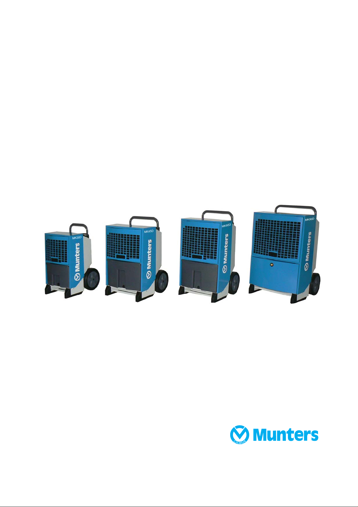
MK30D,MK45D,M
K60D,MK90D
Dehumidifier
Coolingunit
190TEN-1071-C1304 ©MuntersEuropeAB2013
Page 2
Importantuserinformation
Intendeduseofequipm ent
Munters dehumidifiers are intended to be used for the
dehumidification of air. All other uses of the equipment,
or use which is contrar y to the instructionsgiven in
this manual, can cause personal injury and/or machine
damage.
Warrantyandobl
Thewarrantyper
equipment left o
in writing. The
including fre
whichhave fai
manufacture.
has undergon
the specifica
include pro
warranty pe
accordance
specify th
informati
see the se
It is a condition of the warranty that the unit for the full
warranty period is serviced and maintained bya qualified
Munters engineer or Munters approvedengineer.
Access to specific and calibrated test equipment is
necessary. The service and maintenance must be
documented for the warranty to be valid.
Always
faults
incor
e unit type and manufacturing number. This
on is stamped on the unit identificationplate,
ction Marking.
contact Munters for service or repair. Operating
can occur if the unit is maintained insufficiently or
rectly.
iod is valid from the date the
ur factory,unless otherwise advised
warranty is limited to a free exchange
e freight of the faulty unit or components,
led as a result of faulty quality or defects in
Munters guarantees that the unit supplied
e thorough testing to ensure that it meets
tions given here. All warranty claims must
of that the fault has occurred within the
riod and that the unit has been used in
with the specifications. All claims must
igations
Note!
The contents of this publication can be changed without
prior notice. This publication contains information
which is protected by copyright laws. No part of this
publication may be reproduced,stored in a system for
information retrieval or be transmitted in any form, in
any manner without Munters’ written consent. Please
send any comments regarding the contents of this
publication to:
Munters Europe AB
Technical Documentation
P O Box 1150
SE - 164 26 KISTASweden
e-mail: t-doc@munters.se
Safety
In this publication h azardous activities are indicated and
preceded by the common hazard symbol.
WARNING!
isused inthispublicationto indicateapossibledangerthat
couldlead topersonalinjury.Aninstruction isnormallygiven,
followedby ashortexplanation,plus thepossibleeffectsif
theinstruction isnotfoll owed.
CAUTION!
isused inthispublicationto indicateapossibledangerthat
couldlead todamagetothemachineorother equipment
and/orcause environmentaldamage. Aninstruction
isnormallygiven,followedbyashortexplanation,plus
thepossible environmentaleffectif theinstructionisnot
followed.
NOTE! Usedtoaccentuatesu pplementaryinformation
thatis requiredforproblem-freeuseoroptimaluseofthe
unit.
ii Importantuserinformation 190TEN-1071-C1304
Page 3

Tableofcontents
Importantuserinfor
Intendeduseofequi
Warrantyandobligations .............
Note! ...................................
Safety ..................................
Tableofconten
1 Introduction ................................. 1
1.1 General ................................
1.2 UnpackingoftheunitsMK30D-
MK60D .................................
1.3 Unpackingof theunit (MK90D) .......
1.4 Marking ................................
1.5 Transportofthedehumidifier .........
1.6 Stacking ................................
1.7 Operationprinciple ....................
1.8 Mainc
1.9 Watertank (MK30D-MK60D) .........
1.10 Driptray(MK90D) .....................
2 Installation ................................... 6
2.1 Electrical connection ..................
2.2Co
2.3 Remotesignals .......................
3 Operation .................................... 8
3.1 Control panel ..........................
3.2 Switchingon/off .......................
3.3 Internalhygrostatoperation ..........
omponents .....................
nnectionof humidistat .............
mation ...............
pment ...........
ts ...........................
10
ii
ii
ii
ii
ii
iii
1
1
1
2
3
3
3
4
4
5
6
7
7
8
9
3.4 Externalhygrostato
3.5 Hourcounter ...........................
3.6 Display texts ...........................
3.7 Textdisplayswhennotconnectedto
mains ...................................
3.8 Replacingthememory battery .......
3.9 Error messages .......................
3.9.1 MK30D-MK60D ................
3.9.2 MK90D .........................
4 MaintenanceandService ................. 17
4.1 Monthlypreventivemaintenance
(MK30D-MK60D) .....................
4.2 Monthlypreventivemaintenance
(MK90D) ...............................
4.3 Annualpreventivemaintenance
(MK30D-MK90D) .....................
5 Troubleshooting ........................... 19
6 TechnicalSpecification .................... 20
6.1 DimensionsMK30D-MK60D .........
6.2 DimensionsMK90D ..................
6.3 Tec
7 Wiring diagrams ............................ 22
7.1 MK30D-MK60D .......................
7.2 MK90D .................................
parepart lists ..............................
8S
.1MK30D-MK60D .......................
8
8.2 MK90D ................................
h
nical data .........................
peration .........
10
11
12
13
14
15
15
16
17
17
18
20
20
21
22
2
2
26
28
4
6
190TEN-1071-C1304 Table ofcontents iii
Page 4
1Introduction
1.1 General
Dehumidifier MKD-series
The Munters MKD-series dehumidifi
to locations where d ehumidificati
ers are available in four (4) different sizes and they can easily be moved
on of air is required.
WARNING!
Itis the resp onsibilityoftheoperatortoreadandunderstandthisservice manualandotherinformatio n prov ided,
andtousethecorrectoperatingprocedures.
Read the entire manual before the initial start-up of the dehumidifier. Awareness of the correct operating
procedure for the machineand its safety devices is important, to avoid damage or injury.
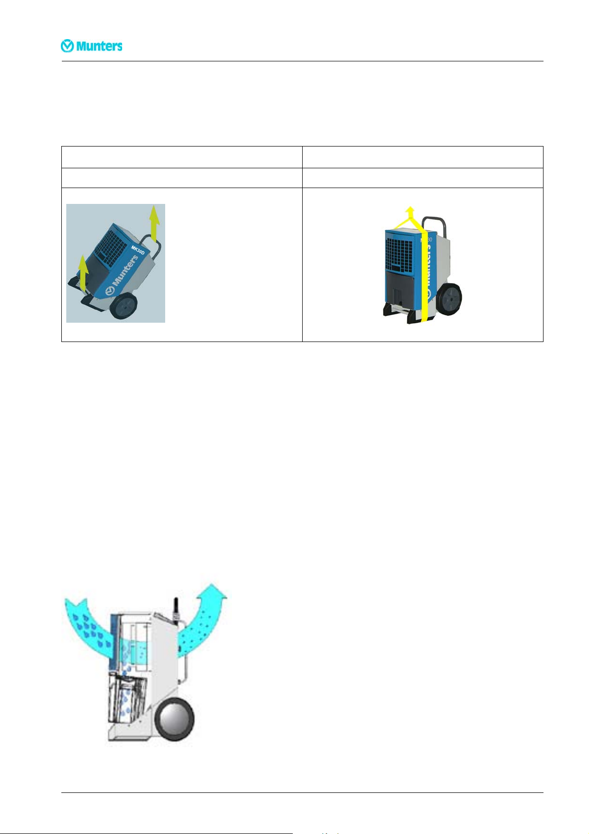
1.2 UnpackingoftheunitsMK30D-MK60D
WARNING!
Ifthedehumidifierha
least1hourbeforepu
Followthese steps to unwrap the unit and make it ready for use
1 Open the cardboard boxin the top
2 Tilt the box with the handle and wheels towards the fl oor
sbeenlaiddownduringtransport,itisimperativethatyouplaceitinuprightpositionforat
tintoservice!
3 Pull the handle of the dehumidifier and wheel the dehumidifier out of the boxstill lying down
4 Tilt the dehumidifier to an upright position
5 Loosen the knobs, pull the handle up to the desired height and retighten the knobs
6 Removethe protective foil on the control panel
1.3 Unpacki
ngoftheunit(MK90D)
WARNING!
Ifthedehumidifierhasbeenlaiddownduringtransport,itisimperativethatyouplaceitinuprightpositionforat
least1hourbeforeputintoservice!
1Unwr
2Li
3C
ap and lift the boxfrom the dehumidifier
ft the dehumidifier clear of the pallet
onnect the drain outlet stub which is supplied with the dehumidifier
1 Introduction 190TEN-1071-C1304
Page 5
Dehumidifier MKD-series
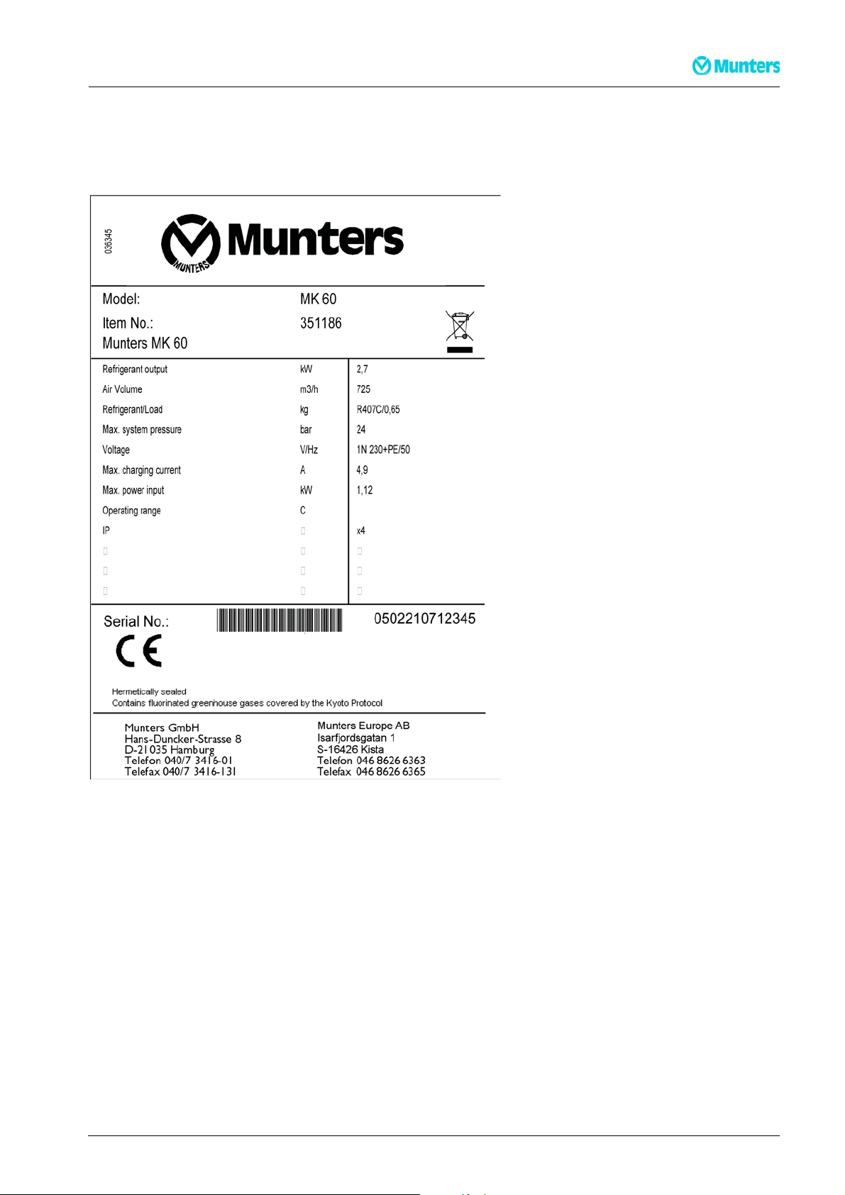
1.4 Marking
MK30D-MK60D: The identification plate is placed behind the bucket inside the dehumidifier.
MK90D:The identification plate is placed at the side of the dehumidifier
D
D
3-32
190TEN-1071-C1304 Introduction 2
Page 6
1.5 Transportofthedehumidifier
NOTE! Observelocalworkingenvironmentrulesasregardsheavylifting
Twopeopleoracranecanmovethedehumidifier. See the instructions below
2 people Hoist/crane
Lift as shown below Lifting using a c argo strap
Dehumidifier MKD-series
The wheels are positioned such that the machine can be pulled upstairs without damage to the cabinet or
stairs.
1.6 Stacking
Max. two dehumidifiers should be stacked on top of eachother. Press the handle of the lower dehumidifier
to the bottom before stacking. The handle then fits a notch on the upper dehumidifier.
1.7 Operationprinciple
The following describes the air flow through the dehumidifier:
1. A fan draws in humid air through a filter to the dehumidifier
2. The air is cooled down and humidity/water drops are led down to the water tank
3. The air is reheated by the operation of the dehumidifier (approx. increase in temperature is +5 °C)
3 Introduction 190TEN-1071-C1304
Page 7
Dehumidifier MKD-series
Due to the repeated air circulation thr
whereby achieving rapid but gentle d
sensor is connected.
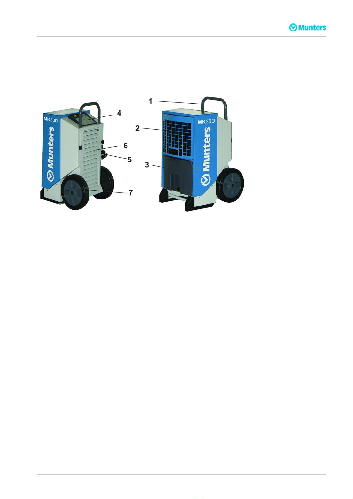
1.8 Maincomponents
ough the dehumidifier, the air humidity is continuously reduced
rying. The dehumidifier will operate continuously if not a humidity
1Handle
2 Supply air inlet with PPI filter behind the grill
3 Water tank (MK30D-MK60D)
4 Control panel
5 Powercable
6Dryairoutlet
7Wheels
1.9 Watertank(MK30D-MK60D)
Water is collected in the water tank. Alternatively, you can also setup the dehumidifier for permanent
drainage with the adapter for hose connection . When the water tank is full, the dehumidifier shuts off
automatically. Operationof the unit is not possible while the water tank is removed.
190TEN-1071-C1304 Introduction 4
Page 8
Dehumidifier MKD-series
1.10 Driptray(MK90D)
The drip tray catches condensation and is fitted with an outlet branch that has a 1/2" tapping (enclosed)
5 Introduction 190TEN-1071-C1304
Page 9
Dehumidifier MKD-series
2Installation
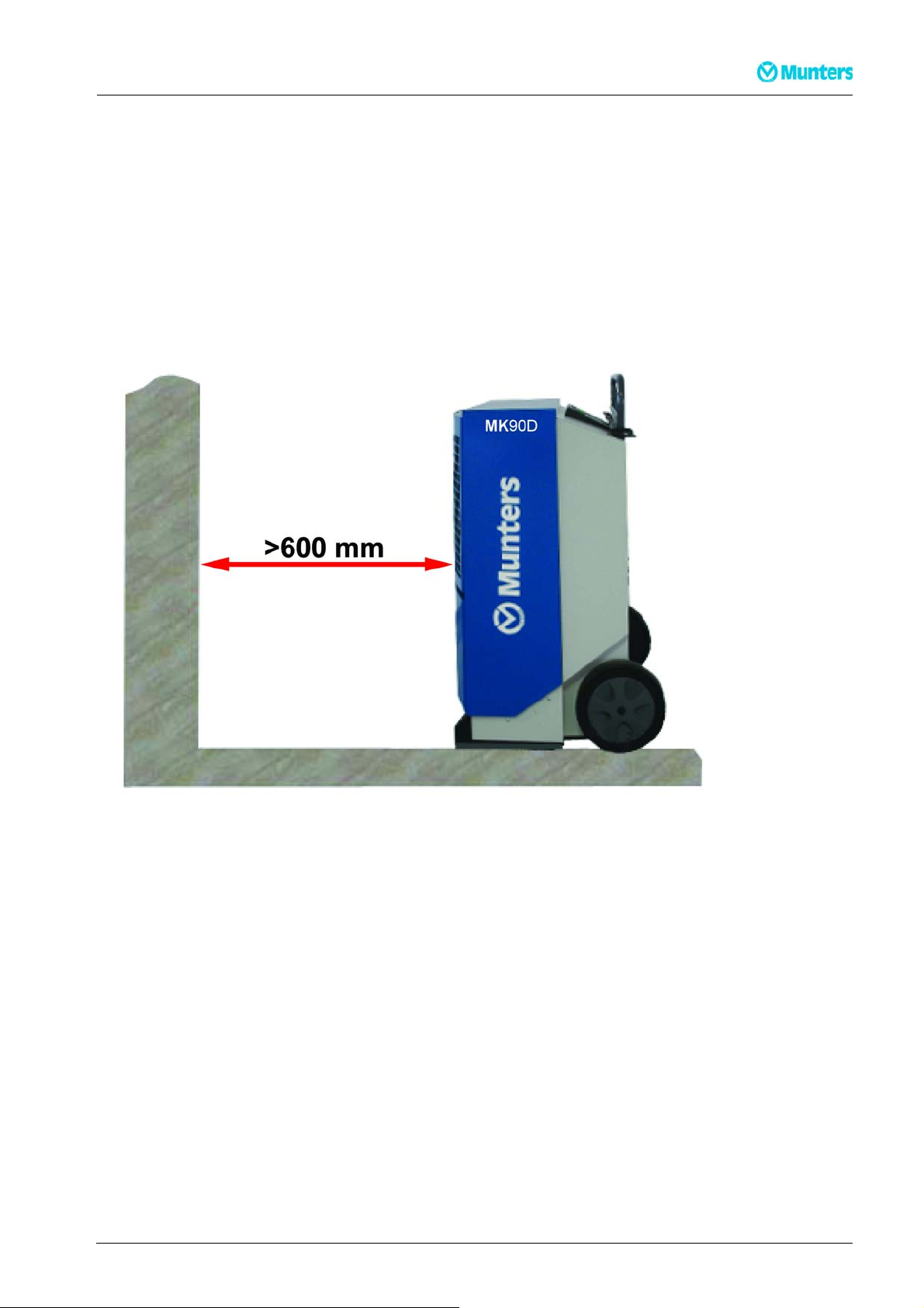
Place the dehumidifier
■ in the middle of a room if possible to ensure good air circulation
■ where air can be sucked in freely through the filter and blownout on the opposite side
■ with a minimum distance on the supply air side from a wall of about 600 mm. The minimum distance on
the dry air side should be 3 m
■ away from any source of heat e.g. a radiator
In addition, ensure that windows and doors are closed in the room to be dehumidified.
2.1 Electricalconnection
The dehumi
10A fuse o
190TEN-1071-C1304 Installation 6
difier is complete with cable and plug and ready for connection to a 230V/50Hz socket with a
r a 16A circuit breaker.
Page 10
Dehumidifier MKD-series
2.2 Connectionofhumidistat
The connection socket for the humidistat is located at the power cable entry.
The humidistat shall be mounted 1–1.5 m. above the floor and positioned so that it is not exposed directly to
dry air from the unit or incoming moist air from opening and closing doors. It may not be placed close to a
heat source or so that it is exposed to direct sunlight. The humidistat shall be a single stage humidistat and
connected so that the controlling circuit closes as relative humidity increases. The connecting cable shall be
screened and have copper conductors with a minimum cross-section area of 2 x 0.75 mm2.
2.3 Remotesignals
If an external alarm or run signal is required use terminal 24 and 25 which are connected by an electronic
relay. The run signal to be connected at terminal 22 and 23. If an error occurs there is no longer connection
and the alarm will start. Max 24V DC and 1,5mA.
7 Installation 190TEN-1071-C1304
Page 11
Dehumidifier MKD-series
3 Operation
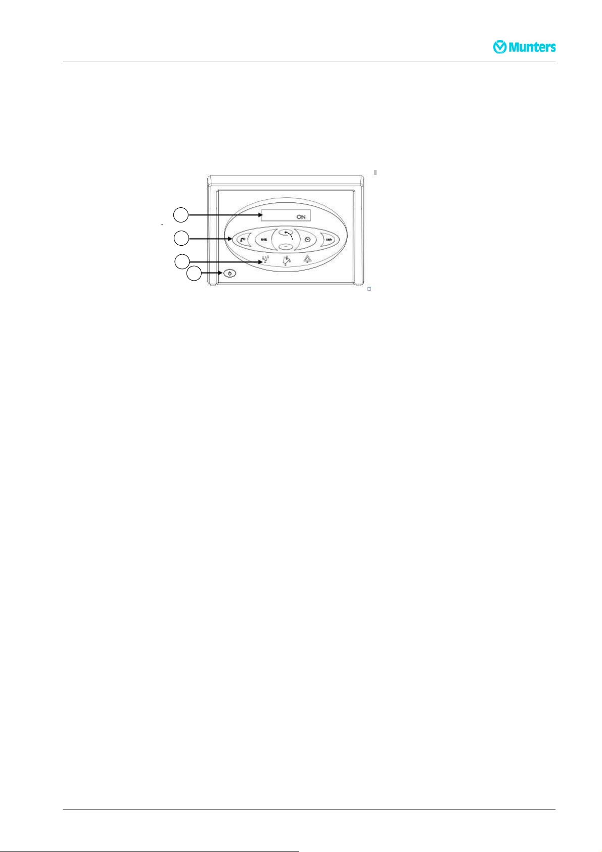
3.1 Controlpanel
All functions are controlled from the integrated control panel.
1Display
2 Function keys
3 Status
indicators
1
2
4 Main switch
3
4
Main functions
■ Manual or auto operation (built-in adjustable hygrostat).
■ External hygrostat socket.
■ .Display of temperature, relative air humidity, hours and kWh consumption
■ Hour counter and kWh consumed without 230V connection.
■ Adjustable service interval counter.
Operation described in the user guide in this manual.
190TEN-1071-C1304 Operation 8
Page 12

3.2 Switchingon/off
The table below showsoperation of the on/offfunction and display texts
Key Display
ON constant operation
INT HYG ON operation controlled by internal hygrostat
INT HYG STOP if internal hygrostat set point is reached
EXT HYG ON operation controlled by external hygrostat
EXT HYG STOP if exter nal hygrostat set point is reached
Switch off
Dehumidifier MKD-series
The green LED indicates active dehumidification
9 Operation 190TEN-1071-C1304
Page 13

Dehumidifier MKD-series
3.3 Internalhygrostatoperation
Step Key Feedback
Press and
hold
HYG SET RHxxx% - will flash for 5 seco
switch to internal hygrostat con
set point is reached, the displa
trolled operation with set point (once the
ywillshowINT HYG STOP).
nds. The dehumidifier will then
Press +/- briefly to set the RH% value in during t he above5 second period.
The new value will be saved after a further 5 second period after the last
key is pressed
Press HYG OFF- will flash for 5 seconds. The dehumidifier will then switch to
constant operation
3.4 Externalhygrostatoperation
If an external hygrostat is connected, the machine will automatically switch over to using it. Any adjustment
of the set point must now be made on the external hygrostat. (once the set point is reached, the display will
show EXT HYG STOP)
190TEN-1071-C1304 Operation 10
Page 14

Dehumidifier MKD-series
3.5 Hourcounter
The built in hour counter logs the total number of operating hours (cannot be reset) and the numberof
hours left until the next service, which can be adjusted. The service hour counter is disabled upon delivery.
Step Key Feedback
Press and
hold
SERVICE xxxxh shows the number of hours to the next authorised
service. This value is saved automatically after 5 seconds of flashing, and
the function will activate if not already activated. When the set number
of hours for service intervals has expired, the display will switch to
SERVICE.Press + /- briefly to set a new service value. The new value will
be saved 5 seconds after the last key is pressed
Press +/- briefly to set a new service value. The new value will be saved 5
seconds after the last key is pressed
Press SET SERVICE OFF- deactivates the service timer function
11 Operation 190TEN-1071-C1304
Page 15

Dehumidifier MKD-series
3.6 Displaytexts
The table below shows how to operate the operating information functions
Key Feedback
XXºCshows the current room temperature
Actual RH% shows the actual relative air humidity
value measured
XX kWh, shows total energy consumption.
Cannot be reset
xxxxh shows the t
for the machine.
otal number of operating hours
Cannot be reset
190TEN-1071-C1304 Operation 12
Page 16

Dehumidifier MKD-series
3.7 Textdisplayswhennotconnectedto mains
The machine has a built-in battery to allow reading text displays when not connected to the mains. The
following texts can be read when not connected to the mains:
Key
hold down
and
press once
hold down
Feedback
Displays total energy consumption in kW h.
Shows total number of operating hours for the dehumidifier
press once
13 Operation 190TEN-1071-C1304
Page 17

Dehumidifier MKD-series
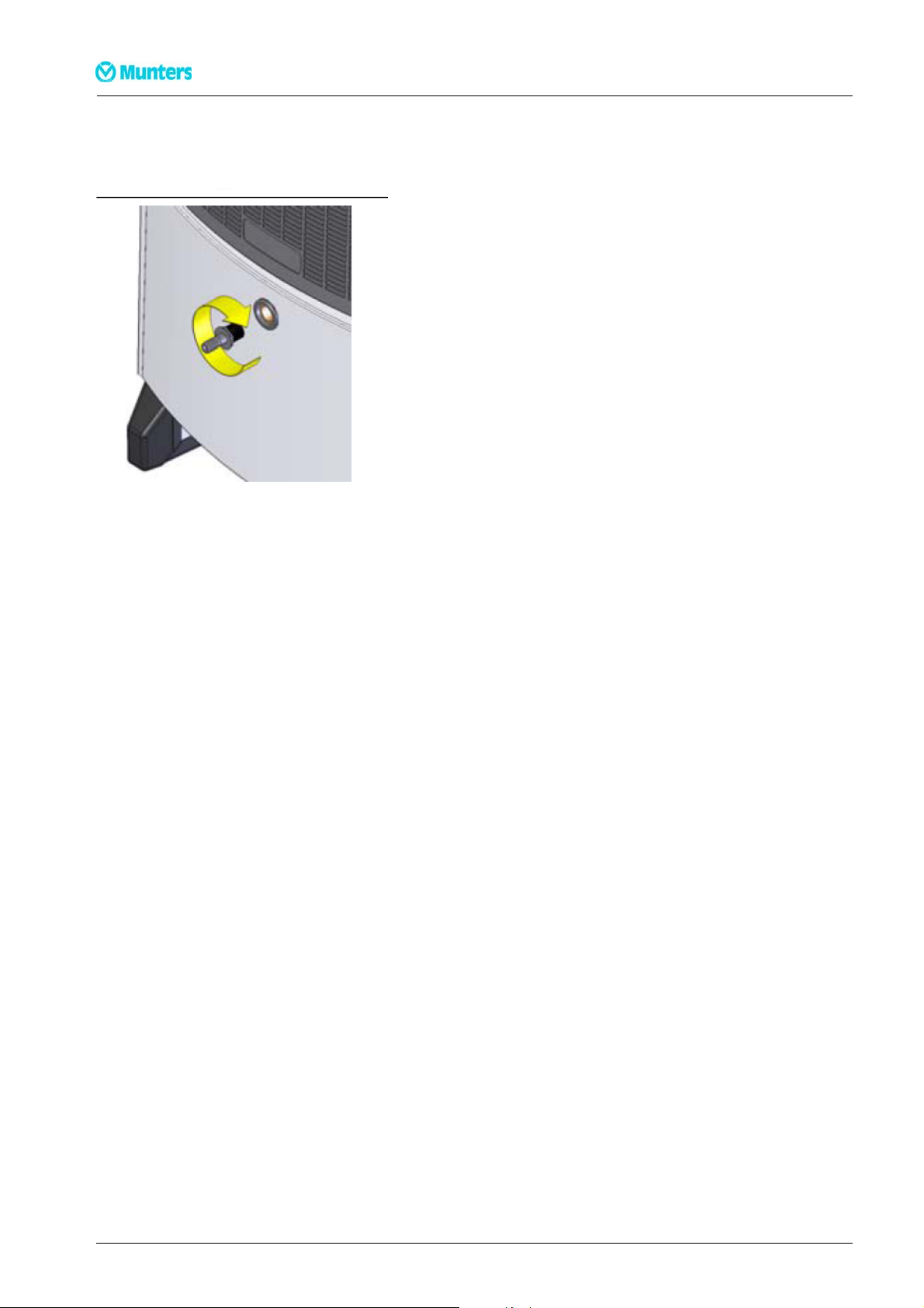
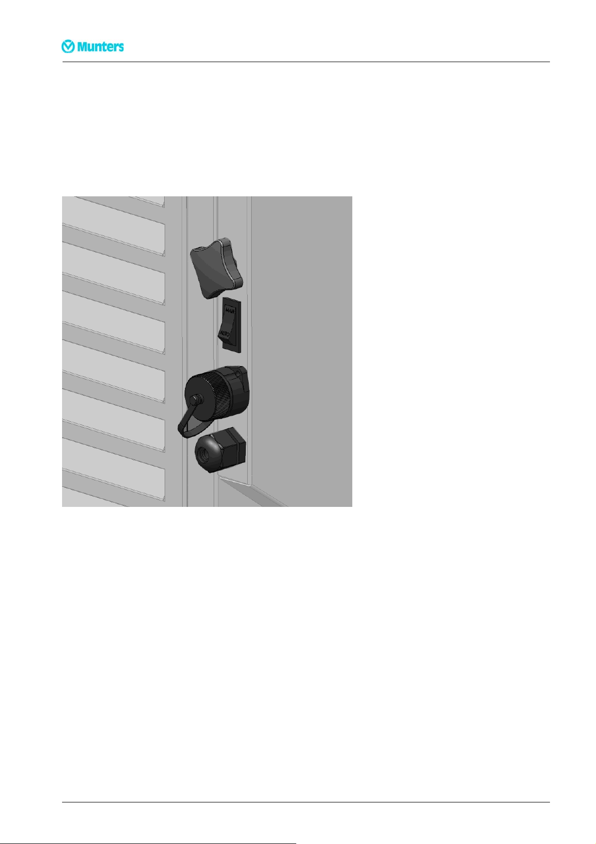
3.8 Replacingthememorybattery
If the hour counters cannot be read when disconnected from mains, it is probably due to flat memory
battery. Replacement procedure:
WARNING!
Alwaysdisconnectfromthemainsbeforechangingbattery
Action
1 Slacken the screws on both side of the
control panel, and carefully lift the
panel up using the top edge
2 Cut the cable tie holding the battery. Replace the battery, using a new cable tie max. 2.5 mm wide.
Use Alkaline AAA batteries
on pag
e 22.
only Illustration of PCB with battery included in the wiring diagram
190TEN-1071-C1304 Operation 14
Page 18

Dehumidifier MKD-series
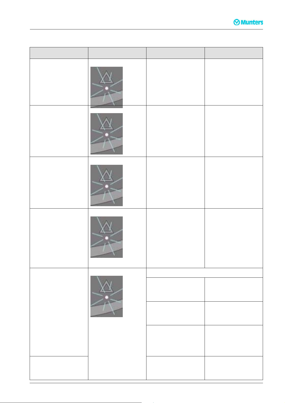
3.9 Errormessages
An overwiev of possible err ors which prevent normal operation.
3.9.1 MK30D-MK60D
Errormessages Illustration Cause Remedy
Yellow light on centre
LED with emptying
symbol and FULL on
display. Seeemptying
guide below, or check
pump outlet
Red light on right
warning LED HIGH
TEMP on display
Red light on right
warning LED
AMBIENT TEMP
on display
Water container is full
or fault on water pump
(accessory)
Pressure or temperature
in high pressure element
too high
Room temperature out
of normal range
See emptying guide
below, or check pump
outlet
Check filter and
dehumidifier for dirt
in airways
Place the dehumidifier in
the specified temperature
range, between 3°-32ºC
Red light on right
warning LED
SENSOR FAILon
display. One of the
internal sensors is
defective. Use the +/keys to toggle between 3
possible errors
Red light on right
warning LED LP
STOPon display
SENSOR FAIL
1: EVAP FAIL
Evaporator
Requires an authorised
service technician
thermometer defective
2: COND FAIL
Condenser
Requires an authorised
service technician
thermometer defective
3: ROOM FAIL
The internal room
Requires an authorised
service technician
thermometer is
defective
Leak in cooling circuit Requires an authorised
service techn ician
15 Operation 190TEN-1071-C1304
Page 19
Dehumidifier MKD-series
3.9.2 MK90D
Errormessages Illustration Cause Remedy
Red light on right
warning LED HIGH
TEMP on display .
Red light on right
warning LED HIGH
TEMP on display
Red light on right
warning LED
AMBIENT TEMP
on display
Water container is full
or fault on water pump
(accessory)
Pressure or temperature
in high pressure element
too high
Room temperature out
of normal range
See emptying guide
below, or check pump
outlet
Check filter and
dehumidifier for dirt
in airways
Place the dehumidifier
in the specified
temperature range,
between 3°-32°
Red light on right
warning LED
SENSOR FAILon
display. One of the
internal sensors is
defective. Use the +/keys to toggle between 3
possible errors
SENSOR FAIL
1: EVAP FAIL
Evaporator
thermometer defective
2: COND FAIL
Condenser
thermometer defective
3: ROOM FAIL
The internal room
thermometer is
defective
Requires a n authorised
service technician
Requires a n authorised
service technician
Requires a n authorised
service technician
Red light on right
warning LED LP
Leak in cooling circuit Requires a n authorised
service technician
STOPon display
190TEN-1071-C1304 Operation 16
Page 20

Dehumidifier MKD-series
4 MaintenanceandService
The unit includes mechanical and electrical parts and the unit is often placed in a rough environment where
the components are exposed to different climate conditions. Therefore the unit will need preventive
maintenance on a regular basis.
Proper maintenance of the unit is necessary in order to achievetrouble-free operation. This section contains
description of the recommended monthly and annual maintenance.
CAUTION!
Alwaysdisconnectthepowerc
4.1 Monthlypreventivemaintenance(MK30D-MK60D)
Followthis procedure to carr y out the monthly preventive maintenance:
1 Open the front grill by tilting it outwards
2Removethefilter. Either rinse it with lukewarm soapy water or vacuumclean it if the filter is only
a little dir ty. Change the filter if it is very dirty.
ablefromtheunitbeforedoinganypreventivemaintenance!
3 Clean the water tank
4 Removethe two screws in each side and tilt the jacket outwards about 30º
5 Lift the jacket up and clear of the dehumidifier
6 Clean the evaporator coil by brushing with a soft brush and vacuum-clean/compressed a ir. Mount
the jacket and put the water tank back in place Note! C heck that the water tank is fitted correctly
4.2 Monthlypr
Followthis procedure to carr y out the monthly preventive maintenance:
1 Open the front grill by tilting it outwards
2Removethefilter. Either rinse it with lukewar m soapy water or vacuum clean it if the filter is only a
little dirty. Change the filter if it is very dirty
3CleanthedriptrayNote !When you refit t he drip tray, make sure that the back edge of the drip tray
rests on the edge inside the dehumidifier.
4 Removethe two screws in each side and tilt the jacket outwards about 30°
5 Lift the jacket up and clear of the dehumidifier
eventivemaintenance(MK90D)
6 Clean the evaporator coil by brushing with a soft brush and vacuum-clean/compressed a ir
7 Mount the jacket
17 MaintenanceandService 190TEN-1071-C1304
Page 21

Dehumidifier MKD-series
4.3 Annualpreventivemaintenance(MK30D-MK90D)
Followthis procedure to carry out the annual preventive maintenance:
1 Carry out the monthly maintenance as described above
2 Vacuum-clean the unit; be very thorough with the condenser and the evaporator. If the unit is very
dirtymoveontostep3and5otherwisemoveontostep5
3 Spray water based soap on the:
■ Evaporator-/condenser coil
■ Fan blades
using a household spray or the like
4 Carefully clean the unit (be extra careful around the fins) with water, however,not directly on electrical
components
5Checkthefan
6 Mount front- and rear jacketand water tank (Only MK30D-MKD60)
7 Check and tighten all coverplate screws as necessary
8 Check that the hour m eter is running.
190TEN-1071-C1304 MaintenanceandService 18
Page 22
5 Troubleshooting
Dehumidifier MKD-series
Use the table below to localise and co
Problem Possible Cause Action
■ Dehumidifier will not start
■ Display not switched on
■ Dehumidifier will not start
■ Green light not on
■ HYG STOP shown on
display
■ Yellowlight on display shows
Full
rrect problem s or errors:
Plug not in mains socket Check dehumidifier is connecte
to the mains. Check the mains
ting
e
,or
n. See
ygrostat
re to rise
The hygrostat has measured
air humidity lower than th
point, and switched off t
eset
osave
power
Room temperature is be
3°Candthedehumidifi
is automatically pu
low
er
toutof
socket if necessary by connec
another electrical applianc
Reduce hygrostat set point
switch to manual opera tio
the section on Inte rnal h
operation, chapter.3.3
.
Wait for the temperatu
above 3 °C
operation
Container full or pump
(accessory) blocked
Empty water container or clear
pump blockage
d
■ Dehumidifier running
■ Green light on
■ SERVICE flashing on
Service interval set has expired Service the product as specified
in the section on service counter
expiry
display
■ Dehumidifier running
■ W hen RH% activates,the
RH% sensor defective Replace RH% sensor
display shows SENSOR
FAIL
■ kW h and hours without
Memory battery flat Replace battery. See chapter 3.8
power not displahyed
NOTE! •
•Befo
reaso
Ifthemachineisnotworkingproperly,switchoffimmediately!
restartingtroubleshooting,waitforoneminute,astheelectronicscouldhavecutoff themachineforsafety
nsy
If the dehumidifier will not restart, contact Munters. This also applies if the machine runs without
condensing any water. There may be a fault on the cooling c ircuit which will require a service technician
19 Troubleshooting 190TEN-1071-C1304
Page 23
Dehumidifier MKD-series
6 TechnicalSpecification
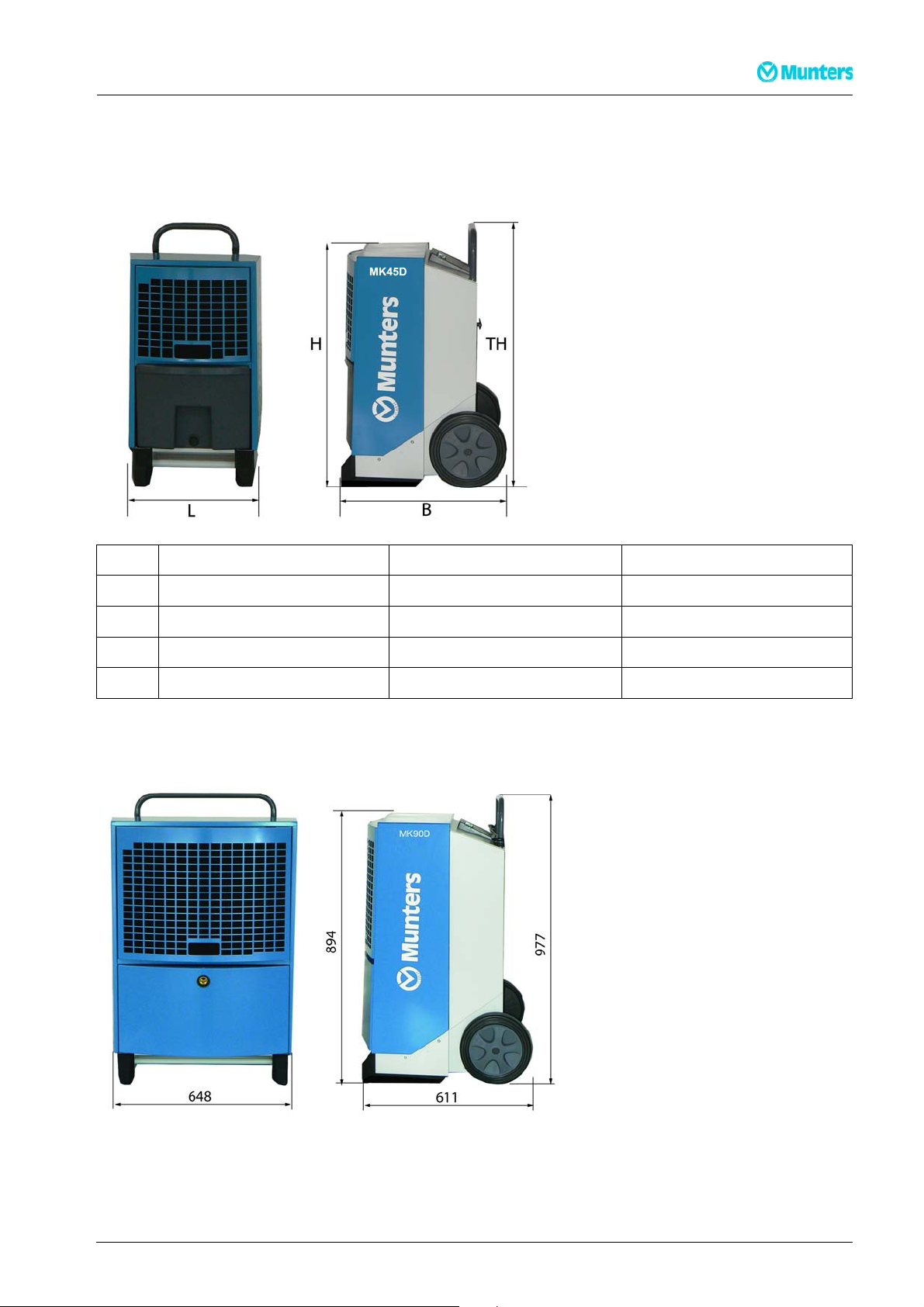
6.1 DimensionsMK30D-MK60D
mm MK30D MK45D MK60D
L 414 539 539
B 506 530 530
H 736 822 903
TH 1023 1190 1270
6.2 DimensionsMK90D
190TEN-1071-C1304 Techn icalSpecification 20
Page 24
6.3 Technicaldata
Dehumidifier MKD-series
MK30D MK45D MK60D MK90D
Operating range -
%RH 40-100
humidity
Operating range -
ºC 3-32
temperature
Power supply V/Hz 230/50
Max. amperage A 2,7 3,6 4,9 7,2
Max. input kW 0,59 0,81 1,12 1,65
Air output m3/h 250 350 725 1000
Refrigerant -- R134a R407C R407C R407C
Refrigerant charge kg 0,410 0,450 0,650 1,6
Water tank capacity l 7,1 13,8 13,8 --
Sound level 1 m
dB 56 59 62 62
distance
Weight kg 32 42 46 62
Safety class IP x4
Filter PP1 15
kWh % +/- 5%
21 TechnicalSpecification 190TEN-1071-C1304
Page 25
Dehumidifier MKD-series
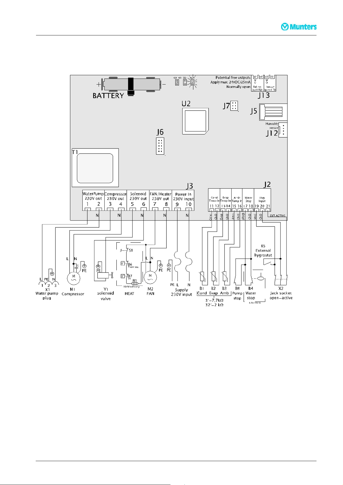
7 Wiringdiagrams
7.1 MK30D-MK60D
Descripti
190TEN-1071-C1304 Wiringdiagrams 22
on on next page
Page 26

Dehumidifier MKD-series
Pos Description Pos Description
B1 Condensorsurface temp. sensor J6 Notinuse
B2 Condensorsurface temp. sensor J7 Factorysettings
B3 Ambienttemp. sensor J12 Internalhygrostat
B4 “Fullwatertank”sensor J13 Extraoutput
B5 Externalhygrostat (acce
B6 Thermostat(3OS /40Sonl
B7 OverTemperature(3OS
B8 Externalpump alarm
D12 LED+5VDCsupplyc
D19 LEDIceonevapor
D20 LEDDefrosting
J2 Lowvoltagec
J3 230V conne
J5 Notinuse
ctions
(accessory)
ontrol
atorsurface
active
onnections
ssory)
y)
/40S only)
M1 Coolercompressor
M2 Fanmotor
R1 Heatingelement(3OS /
S1 Heating elementon/
T1 Transformer
U2 CPU
X1 Waterpumpplug
X2 Jack plugfor
Y1 Solenoid v
externalhygrostat
alve(pressure equalisation)
off(3OS/4OSonly)
4OSonly )
23 Wiringdiagrams 190TEN-1071-C1304
Page 27

Dehumidifier MKD-series
7.2 MK90D
Descriptiononnextpage
190TEN-1071-C1304 Wiringdiagrams 24
Page 28

Dehumidifier MKD-series
Pos Description Pos Description
B1 Condensorsurface temp. sensor J6 No t inuse
B2 Condensorsurface temp. sensor J7 Factorysettings
B3 Ambienttemp. sensor J12 Internalhygrostat
B4 na J13 Extraoutput
B5 Externalhygrostat (acce
B6 na M2 Fanmotor
B7 na R1 na
B8 Externalpumpalarm
D12 LED+5VDCsupply c
D19 LEDIceonevapor
D20 LEDDefrosting
J2 Lowvoltagec
J3 230Vconne
J5 Notinuse
active
onnections
ctions
ssory)
(accessory)
ontrol
atorsurface
M1 Coolercompressor
S1 na
T1 Transformer
U2 CPU
X1 Waterpump plug
X2 Jackplugfor
Y1 Solenoidv
externalhygrostat
alve(pressure equalisation)
25 Wiringdiagrams 190TEN-1071-C1304
Page 29

Dehumidifier MKD-series
8 Sparepartlists
8.1 MK30D-MK60D
Pos MK30D MK45D MK60D Description
1 9077036741 9077036986 9077037110 Frontcover complete
2 9077036826 9077036826 9077037101 Fanblades
3 9077032857 9077032857 9077032873 Fanmotor
4 9077032854 9077032854 9077032880 Fanmount
9077072410 9077072410 9077072398 Fancomplete(pos 2,3,4)
5 9077036744 9077036960 9077037106 Exhaustgrille
6 9077036762 9077036959 9077036959 Handle
7 9077036847 9077036847 9077036847 Fingerscrew M6/15,2pcs
8 9077072418 9077072418 9077072418 Mountingjacket RJplug
9 9077036730 9077036983 9077036983 Foot—2 pcs
10 9077036844 9077037094 9077037094 Wheelaxle
11 9077036731 9077036731 9077036731 Wheels—2 pcs
12 9077036896 9077036971 9077036971 Vibrationdampers,3pcs. forcompressor
190TEN-1071-C1304 Sparepartlists 26
Page 30

Dehumidifier MKD-series
Pos MK30D MK45D MK60D Description
13 9077036895 9077036961 9077037107 Compressor
14 9077036743 9077064863 9077037102 Condenser/ Evaporatorsurfaces
15 9077072258 9077072260 9077072262 Frontgrille,including filter
16 9077036755 9077036957 9077037104 Filter,air
17 9077036737 9077036988 9077036988 Container,complete
18 9077036845 9077036845 9077036845 Threadedplug,complete
19 9077036740 9077036740 9077036740 Solenoidcoil
20 9077036733 9077036733 9077036733 Waterstopsensor
21 9077072416 9077072416 9077072416 Sensorset AMB/RH
22 9077071053 9077071057 9077071057 Cableset comple
23 9077072414 9077072414 9077072414 Powercord 3,5m
24 9077037173 9077037173 9077037173 Junctionbox
12
36758
036893
9
907707104
90770724
90770
9077
25 907707104
26 90770724
27 na 9077046
28 90770
29 9077
12
167
37105
036893
9
907707104
90770724
9077038
90770
9077
12
570
37105
036893
9
Controlpa
MainPCB
Thermov
ter
Dryfil
noidvalve 1/4”
Sole
alvewithclip
teincl. sensors
.withplug
gasket
nelcomplete, incldisplay
%
27 Sparepartlists 190TEN-1071-C1304
Page 31

Dehumidifier MKD-series
8.2 MK90D
Pos Number Description
1 9077037135 Frontcovercomplete
2 9077037125 Fanblades
3 9077032880 Fanmount
4 9077037124 Fanmotor
Fan,complete,(pos2,3,4)
5 9077037130 Exhaustgrille
6 9077037129 Handle
8 9077072418 MountingjacketRJplug
9 9077037134 Foot—2pcs
10 90770371 33 Wheelaxle
11 90770367 31 Wheels,3 pcs. forcompressor
12 90770369 71 Vibrationdampers
190TEN-1071-C1304 Sparepartlists 28
Page 32

Pos. Number Description
13 90770371 31 Compressor
14 907707 2420 Driptray
Dehumidifier MKD-series
15 90770371 26 Condensor/Evaporatorsurface
16 907707 2263 Frontgrille,includingfilt
17 907703 7128 Filter,air
18 90770710 62 Lowerfrontplate
19 90770466 27 Hose spigot1/2”
20 907703 6740 Solenoidcoil
21 90770710 63 Cab le setcomplet
22 90770724 14 Powercord3,5m.
23 90770371 73 Junctio n boxga
24 9077071049 Controlpane
16
662
37136
038571
2
MainPCB
Sensorse
r
Dryfilte
oidvalve 1/4“
Solen
malexpansionvalvewithclip
Ther
25 907707241
26 90770724
27 9077011
28 90770
29 9077
sket
lcomplete, incl. display
tAMB/RH%
er
eincl. sensors
withplug
s
29 Sparepartlists 190TEN-1071-C1304
Page 33

Page 34

Page 35

Page 36

AUSTRIA
MuntersGmbH
AirTreatment
Zweigniederlassung Wien
Eduard-Kittenberger-Gasse 56, Obj. 6
A-1235 Wien
Austria
Tel: +43 161 64298- 9251
Fax: +43 1 616 4298-92 98
E-mail:luftentfeuchtung@munters.at
Web: www.munters.at
FINLAND
Munters Finland Oy
Kuivaajamyynti
Hakamäenkuja 3
FI-01510 VANTAA
Finland
Tel: +358 2077 6823 0
E-mail: laitemyynti@mun ters.fi
Web: www.munters.fi
NETHERLANDS
Munters Vochtbeheersing
Energieweg 69
NL-2404 HE Alphen a/dRij n
Netherlands
1 17243 32 31
Tel:+3
Fax: +31 172 44 29 60
E-mail: vochtbeheers ing@munters.nl
Web: http://www.munters.nl
SWITZERLAND
MuntersGmbH
AirTreatment
Zweigniederlassung Rümlang
Glattalstr. 501
CH-8153 Rümlang
Switzerland
Tel: +41 523 4388 86
Fax: +41 52343 88 87
E-mail: info.dh@munters.ch
Web: http://www.munters.ch
BELGIUM
MuntersBelgium S.A.
Air Treatment
Rue du Progrès, 5
4821 Dison
Belgium
Tel: +3287306911
Fax: +3287314 476
E-mail: info@mu ntersbelgium.be
Web: http://www.muntersbelgium.be
CZECHREPUBLIC
MUNTERS CZ, organizacní složka
Air Treatment
Slevacská 2368/ 68
CZ-615 00 BRNO
CzechRepublic
Tel: +420 544 211434
Fax: +420 544 211 436
E-mail: info@mu nters-odvlhcovani.cz
Web: http://www.munters-odvlhcovani.cz
DENMARK
MuntersA/S
Air Treatment
Ryttermarken 4
DK-3520 Farum
Denmark
Tel:+4544953355
Fax:+4544953955
E-mail: info@mu nters.dk
Web: http://www.munters.dk
AUSTRALIA INDIA SINGAPORE USA
Tel:+61288431588 Tel:+9120 668 18 900 Tel:+65 6744 6828 Tel: +1-800-843-53 60
dh.info@munters.com.au info@munter s.in singapore@muntersasia.com dhinfo@munters.com
FRANCE
Munters France SAS
Air Treatment
106, Boulevard Héloise
F-95815Argenteuil Cedex
France
Tel: +33 13 411 57 57
Fax:+33134115758
E-mail: dh@munt ers.fr
Web: http://www.munters.fr
GERMANY
Munters GmbH
AirTreatment - Zentrale
Zentrale
Hans-Duncker-Str. 8
D-21035 Hamburg
Germany
Tel: +49 (0)40 879 690 - 0
Fax: +49 (0)40 879 690 - 131
E-mail: mgd@mu nters.de
Web: http://www.munters.de
ITALY
Munters Italy S.p.A
Air Treatment
Strada Piani 2
I-18027Chiusavecchia
IM
Italy
Tel: +39 01835 21377
Fax: +39 0183 521333
E-mail: marketing@munters .it
Web: http://www.munters.it
POLAND
MuntersSp. z o.o.
Oddzialw Polsce
AirTreatment
ul. Swietojanska 55/3A
81-391 Gdynia
Poland
Tel.: + 48 58 30535 17
Fax:+48586211268
E-mail: dh@munters. pl
Web: http://www.munters.com.pl
SPAIN
MuntersSpain SA
AirTreatment
EuropaEpresarial. Edificio Londres.
C/PlayadeLiencres2.Edi ficio Londres
28230 Las Matas. Madrid
Madrid
Tel:+34916400902
Fax: +34 91 640 1132
E-mail: marketing@mu nters.es
Web: http://www.munters.es
SWEDEN
MuntersEurope AB
AirTreatment
POBox1150
S-16426Stockholm,Kista
Visiting address: Isafjor dsgatan 1,Kista
Entré
Sweden
Tel:+46 8 626 6300
Fax: +46 8 754 85 94
E-mail: avfuktning@mu nters.se
Web: http://www.munters.se
UNITEDKINGDOM
MuntersLtd
Air Treatment
Pathfinder Place 10Ramsay Cour t
Hinchingbrooke Business Park
Huntingdon PE29 6FY
Cambs
United Kingdom
Tel: +44 1480 432243
Fax: +44 1480 413 147
info@munters.co.uk
http://www.munters.co.uk
BRAZIL JAPAN SOUTHAFRICA
Tel: +55 115054 0150 Tel:+81 3 5970 0021 Tel:+2711 9972 000
Web: http://www.munters.com.br E-mail: mkk@mu nters.jp info@munters.co.za
CANADA KOREA TURKEY
Tel: +1-800-843-5360 Tel:+822 761 8701 Tel:+90 216 548 14 44
dhinfo@munters.com munters@munters.kr info@muntersform.com
CHINA MEXICO
Tel: +86 10804 18000 Tel:+52 722 270 4029 Tel:+9714 881 3026
E-mail: marketing@munters .cn munters@munters.com.mx middle.east@munters.com
UAE(Dubai)
www.munters.com
 Loading...