

Page 1

Manual for use and maintenance
MFS
+ CE Declaration of conformity
MFS
Air circulation fan
Models: MFS36 - MFS52
Ag/MIT/UmGB-2085-04/13 rev1.1
Page 2

MFS
Manual for use and maintenance
Revision: No. 1 of 15.04.2013
This manual for use and maintenance is an integral part of the apparatus together with the attached technical
documentation and has been produced with reference to Directive 2006/42/EC, paragraph A, Annex II, and to
ErP Directive 2009/125/CE Commission Regulation 327/2011.
This document is destined for the user of the apparatus: it may not be reproduced in whole or in part, committed
to computer memory as a file or delivered to third parties without the prior authorisation of the assembler of the
system.
Munters Italy S.p.A. reserves the right to effect modifications to the apparatus in accordance with technical and
legal developments.
2
© Munters AB, 2013
Page 3

Index
chapter page
1. CE DECLARATION 5
1.1 Disclaimer 6
1.2 Introduction 6
1.3 Notes 6
1.4 Data for Fan Eco Design Directive 6
2. SAFETY ASPECTS 7
2.1 General 7
2.2 Points to observe 7
3. BEFORE USING 8
3.1 Delivery check 8
3.2 Packaging and transport of assembled fans 8
3.3 Structure 8
4. OPERATING CONDITIONS 9
5. INSTALLATION 10
5.1 Assembly of the fan 10
5.2 Tensioning belt adjuster 11
5.3 Belt tensioner (optional) 14
5.4 Tilting device 15
5.5 Placement of fans 17
5.6 Electrical wiring 17
6. COMMISSIONING 21
7. TECHNICAL DATA 22
7.1 Dimensions 22
7.2 Technical specification 23
7.3 Motor specifications 24
© Munters AB, 2013
3
Page 4

Index
8. MAINTENANCE 25
8.1 Introduction 25
8.2 Cleaning 25
8.3 Belt tensioning check up 25
8.4 Tensioning belt adjuster 26
8.5 Replacement of V-belt 27
8.6 Fan bearing lubrication 28
8.7 Propeller replacement 28
9. SPARE PART LIST 29
10. WARRANTY 37
4
© Munters AB, 2013
Page 5

CE Declaration
CE DECLARATION OF CONFORMITY
(complies with Subparagraph A Annex II Directive 2006/42/EC)
with registered offices in Strada Piani 2 – 18027 Chiusavecchia (IM) – Italy
DECLARES ON ITS OWN RESPONSIBILITY THAT THE APPARATUS
1.
Munters Italy S.p.A.
Designation
Model MFS36 - MFS52
Year of manufacture 2012
CONFORMS WITH THE ESSENTIAL SAFETY REQUIREMENTS STATED
BY APPARATUS DIRECTIVE 2006/42/EC
WITH PARTICULAR REFERENCE TO THE FOLLOWING PROVISIONS:
UNI EN 953:2009, UNI EN ISO 12100:2010, UNI EN ISO 12499:2009,
UNI EN ISO 13857:2008, CEI EN 60204-1:2006 (CEI 44-5).
Circulation fan designed for moving air to control
temperature and humidity in livestock.
© Munters AB, 2013
Chiusavecchia, 15th April 2013
Marco Scomparin
Legal representative
5
Page 6

CE DeclarationChapter1
1.1 Disclaimer
Munters reserves the right to make alterations to specifications, quantities, dimensions etc. for production or other
reasons, subsequent to publication. The information contained herein has been prepared by qualified experts within
Munters. While we believe the information is accurate and complete, we make no warranty or representation for
any particular purposes. The information is offered in good faith and with the understanding that any use of the
units or accessories in breach of the directions and warnings in this document is at the sole discretion and risk of
the user.
1.2 Introduction
®
Congratulations on your excellent choice of purchasing an Euroemme
In order to realize the full benefit from this product it is important that it is installed, commissioned and operated
correctly. Before installation or using the fan, this manual should be studied carefully. It is also recommended that
it is kept safely for future reference. The manual is intended as a reference for installation, commissioning and dayto-day operation of the Euroemme fans.
fan!
1.3 Notes
Date of release: 2012.
Munters cannot guarantee to inform users about the changes or to distribute new manuals to them.
All rights reserved. No part of this manual may be reproduced in any manner whatsoever without the expressed
written permission of Munters. The contents of this manual are subject to change without notice.
1.4 Data for Fan Eco Design Directive
According to the indication of the ErP Directive 2009/125/CE the MFS fan series as circulator fan (fanjet) are not
included in the requirements of the commission regulation 327/2011.
6
© Munters AB, 2013
Page 7

Safety aspects
2.
2.1 General
The safety of fans is assured by Munters in compliance with the safety requirements indicated by the CE label.
Safe functioning is assured only when the installation procedure and the instructions for use have been carefully
followed. The following points must be stressed:
• proper transport procedure must be followed;
• do not remove the safety mesh guards;
• all fans installed at a height lower than 2.7 m from ground level, must be equipped by extra CE safety kits,
which can be ordered;
• if the safety mesh is not installed, the manufacturer is exonerated from all responsability and the use of the
fan is considered improper;
• the maintenance operator must be kept informed on maintenance procedures;
• do not operate the fan without the safety mesh properly installed;
• do not operate the fan without having it firmly fixed to the structure or without complying with the safety
regulations for the electrical connection;
• do not install the fan in places where there might be explosion hazards as described by EN 60079 rules;
• do not handle any material which might produce explosive powders;
• the emission of harmful particles and / or gases into the atmosphere must be within the limits determined
by local authorities;
• the fan is intended to be installed and used by qualified personnel who are familiar with relevant safety
requirements;.
• safety equipment necessary for the prevention of accidents at the mounting and operating site shall be
provided by the buyer in accordance with the regulations prevailing in the local country;
The fan must only be used if it is in perfect operating condition, by personnel, aged
The fan must only be used if it is in perfect operating condition, by personnel, aged
more than 14 years who are perfectly aware of the safety measures and possible
WARNING
WARNING
more than 14 years who are perfectly aware of the safety measures and possible
hazards, and in strict compliance with the instructions given in this manual.
hazards, and in strict compliance with the instructions given in this manual.
2.2 Points to observe
The fan must not be driven by impulsive voltage (frequently on/off voltage). This impulse voltage causes an
excessive build-up of heat in the motor which can lead to motor failure. The temperature of the outer casing of the
motor may be hot to the touch during normal operation.
© Munters AB, 2013
7
Page 8
Before using
3.
3.1 Delivery check
Upon receipt, inspect the fan for external damage and if found, inform the forwarding agent without delay. Check
the data on all the rating plates, especially voltage and frequency. After placing the motor in the working position
(see section 5.1), turn the propeller by hand while the fan is switched off to verify smooth rotation of the propeller.
3.2 Packaging and transport of assembled fans
The fan has a self-supporting structure in galvanised steel and it is usually delivered without packaging. Upon
request fans can be delivered packed in cardboard boxes. Fans should not be permanently stocked one upon
the other, regardless if they are delivered with or without packaging. Handling of the fans should not be done
manually as the fans have no handles or grips. Consequently one of the following alternatives should be used:
• forklift: before loading, make sure the forks are opened as much as possible to avoid bending of the fan
bottom panel;
• crane: fix two bolts in the M8 bushes situated on the sides of the fan housing and hook the lifting cable over
the bolts.
Make sure a steel cable or rope of adequate size is being used when the fan is
WARNING
3.3 Structure
The fans consist of the following components:
• fan housing in galvanised steel without welding spots;
• propeller with four blades in stainless or galvanised steel; blades are fixed to the propeller by high-strength
pop rivets;
• motor: single-phase or three-phases; 50 or 60 Hz; B3 form; F class winding insulation, IP 55 IEC protective
class; asynchronous single-speed;
• pyramidal shape and flat meshes for protection on back and front side;
• wall/column mounting system with tilting mechanism (optional extra); to be used when the fan needs to be
mounted next to a wall or column;
• tilting mechanism with chain (optional extra); to be used when the fan needs to be suspended from the roof
of the structure.
lifted by crane. Fan weights are shown in the technical specification table (see
section 7.2).
8
© Munters AB, 2013
Page 9

Operating conditions
4.
Circulation fans, such as the MFS, are products to be used to circulate the air inside a structure, thereby creating
air movement inside the structure which helps to cool animals down during hot periods.
Normal ambient temperature limits are –25°C to +50°C. Maximum altitude is 1000 m above sea level. Should
a fan be required to operate at a higher altitude, the loss in mass flow (heat removing capacity) due to lower air
density should be taken into consideration.
© Munters AB, 2013
9
Page 10
Installation
5.
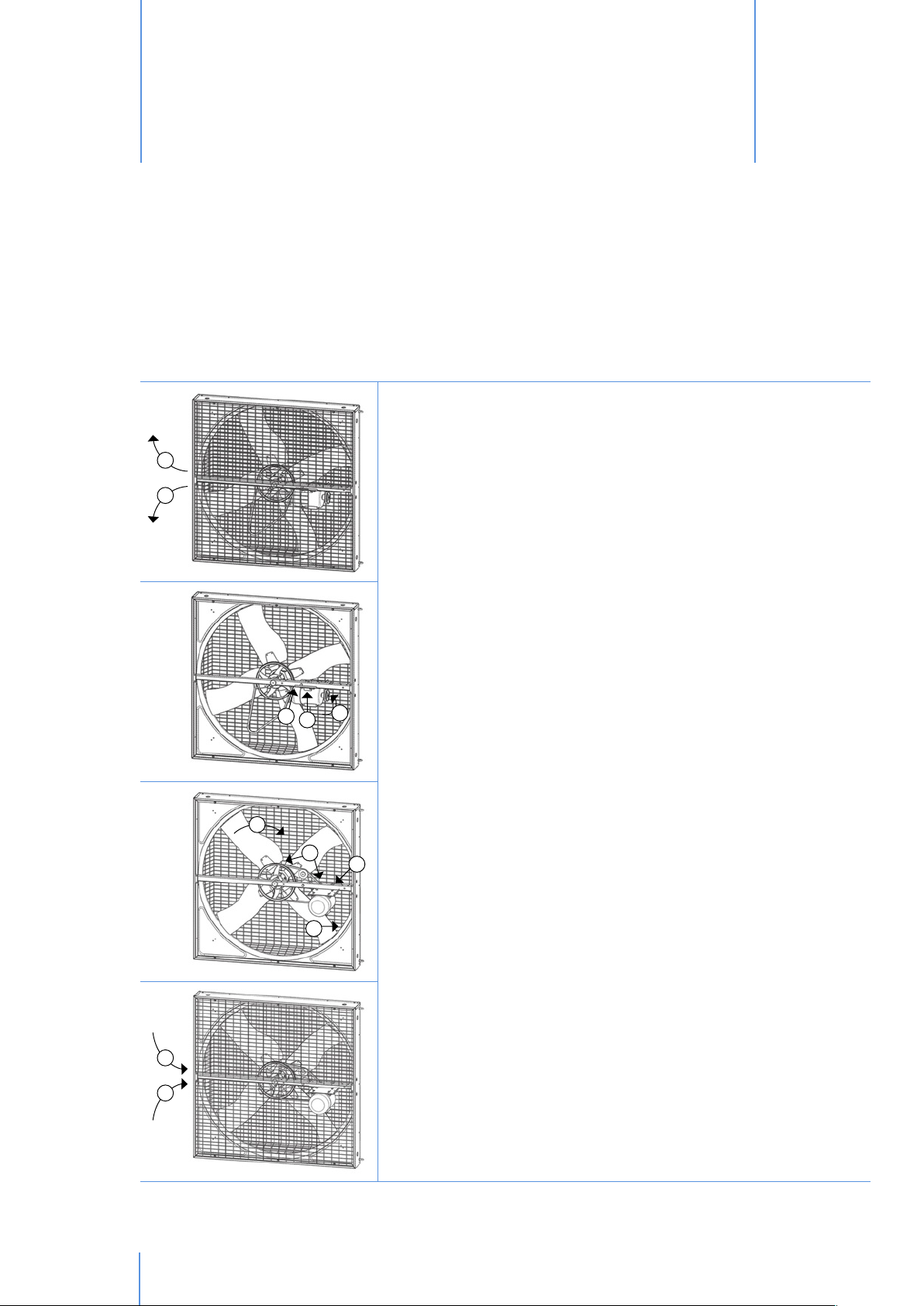
5.1 Assembly of the fans
Fans are delivered with the motor in the transport position to minimise space usage during transportation. To move
the motor to its working position, it is necessary to follow the steps indicated below.
1
1
1. Unscrew the screws holding the flat safety meshes in place and open
the safety meshes.
2. Loosen the bolt in the motor plate closest to the centre of the fan
completely and remove it.
3. Loosen the remaining bolt in the motor plate slightly, but do not
2
6
4
3
5
8
7
remove it.
4. Swivel the motor 90° around the remaining bolt in the motor plate
and re-insert the bolt that was removed from the motor plate and
tighten it slightly.
5. Place the V-belt over the motor pulley and then partially over the
central pulley.
6. Rotate the propeller by hand so that the V-belt gets completely into
the groove on the central pulley.
7. Push the motor away from the centre of the fan to tighten the V-belt.
See section 8.3 for establishing the correct V-belt tension.
8. Tighten the two bolts in the motor plate so that the V-belt remains in
tension.
9. Close the safety meshes, re-insert and tighten the screws.
10
9
9
fig.1
© Munters AB, 2013
Page 11

InstallationChapter5
5.2 Tensioning belt adjuster (only for MFS52 model)
1. Follow steps till n°3 (see section 5.1).
2. Unscrew the M6 nut from the bracket in order to remove the grub
screw. Loosen the M6x60 bolt and remove the L bracket.
3. Swivel the motor 90° around the remaining bolt in the motor plate
and re-insert the bolt that was removed from the motor plate and
tighten it slightly.
4. Reverse 90° the L bracket having the wide side placed on the
central support. Insert the M6x60 bolt trougth the L bracket and
the central support as show in the table below.
5. Start fastening the M6x60.
6. Screw again the M6 nut on the M6 grub screw leaving a small
gap between them.
7. Place the grub screw in the two holes, one located on the motor
plate and the other located on the L bracket; slide the motor plate
in order to be sure to insert the grub screw in both holes. Then
finish tightening the M6x60 bolt.
9
8
8. Place the V-belt over the motor pulley and then partially over the
central pulley.
9. Rotate the propeller by hand so that the V-belt gets completely
into the groove on the central pulley.
10
10. Push the motor away from the centre of the fan to tighten the
V-belt. See section 8.3 for establishing the correct V-belt tension.
© Munters AB, 2013
11
Page 12
InstallationChapter5
11. Be sure to adjust the two M6 nuts and the grub screw, in order to
avoid any clearance of it.
12. Tighten the two bolts in the motor plate so that the V-belt remains
in tension.
fig.2
13. Close the safety meshes, re-insert and tighten the screws.
12
© Munters AB, 2013
Page 13

InstallationChapter5
Holes for pulley
1
2
3
fig.3
Motor
[Hp]
1,0 50
1,0 60
2,0 50
2,0 60
1,0 50
1,0 60
2,0 50
2,0 60
Note: be sure to adjust the grub screw in order to guarantee the correct belt tensioning, by moving the 2 nuts.
Frequency
[Hz]
Tensioner Hole
NO
NO
NO
NO
YES
YES
YES
YES
n°
2
3
1
2
2
2
1
1
© Munters AB, 2013
13
Page 14

InstallationChapter5
5.3 Belt tensioner (optional)
1. Follow steps till n°4 (see section 5.1).
2. Install the belt tensioner in the hole to the left of the motor base (as seen from the air intake side) and tighten
the bolt by hand.
3. Install the new V-belt onto the pulleys. Start by placing the belt onto the motor pulley, then over the idler
pulley and then onto the central pulley. Once the V-belt is partially over the pulley, it might be necessary to
start rotate the propeller by hand to help pull the V-belt completely onto the pulley.
fig.4
4. To torque the belt tensioner to the proper setting place a 24mm wrench onto the 24mm hex on the tensioner.
Turn wrench counterclockwise or clockwise (depend on the fan model) until the single mark on one half of
the belt tensioner is aligned half way between marks 2 and 3 on the opposite half of the tensioner. Hold
tensioner at this setting and tighten the bolt fastening the tensioner to the motor base.
14
fig.5
Mark on base
Second mark on
tensioner arm
© Munters AB, 2013
Page 15

InstallationChapter5
Drive alignment
1. Use a straight edge to check the alignment of the pulleys.
2. Check alignment of belt on idler pulley, it should be centered on the idler pulley. The belt tensioner’s idler
pulley is fixed in position, therefore, alignment must be obtained by adjusting the motor and propeller
pulleys.
3. If an adjustment is needed, remove the belt, then loosen the set screws in the pulleys and move them as
necessary to achieve proper alignment.
4. Remember to tighten the pulley set screws after making an adjustment.
5. Drive alignment is very important for long belt life and proper operation.
Installation now complete, reconnect power to the motor and install outlet or inlet guard.
Idler
pulley
Propeller
pulley
Belt
Motor
pulley
fig.6
Straight edge
5.4 Tilting device
The fan (MFS36-52) can be tilted both in vertical and horizontal as indicated below:
Metal structure
If the fan is directly fixed to a metal structure, M8
bolts - 8.8 type, should be used and screwed into
the proper threaded inserts placed on the body (2
on each side).
fig.7
© Munters AB, 2013
15
Page 16

InstallationChapter5
fig.8
Chain suspension
If the fan is used as a circulator chains should be
fixed to the M8 eyebolts previously installed on the
extremity of the lateral sides by the threaded M8
bushes.
30° 30°
fig.9
fig.10
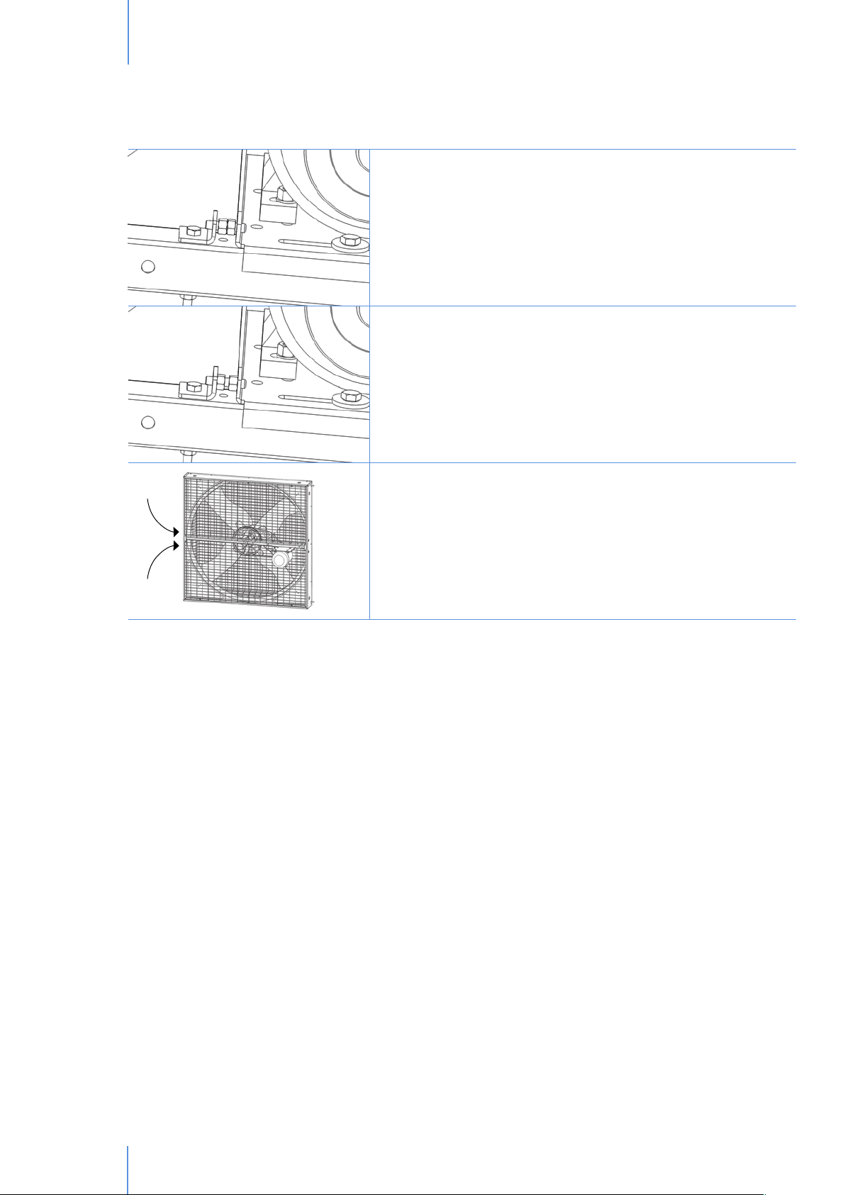
Wall/column mounting system
2
VERTICAL TILTING
1. Loosen both the bottom bolts (it is not necessary
to remove the bolts completely from the fan).
1
2. Tilt the fan to the desired angle.
3. Fasten the two bolts from the step 1.
HORIZONTAL TILTING
1. Loosen side bolts (it is not necessary to remove
the bolts completely from the support).
2
1
2. Tilt the fan to the desired angle.
3. Fasten the bolts from the step 1.
16
fig.11
© Munters AB, 2013
Page 17

InstallationChapter5
!
!
5.5 Placement of fans
NOTE
If the MFS is installed near a wall or similar obstacle, a free space at least of
1,500mm should be left open on the fan air intake side.
min. distance = 1,500m
fig.12
NOTE
In order to comply with CE regulations, fans should be mounted so that the bottom
of the fan is 2.7m or higher from the floor below it. If the fan is to be installed
at a lower height it should be equipped with special safety meshes which are
available as an optional extra.
fig.13
5.6 Electrical wiring
The fan is delivered without an electrical control box, but the fan motor comes already wired. Connection to the
power supply must be done by means of a thermal overload protection switch, whose size depends on motor
power. For safety reasons the overload switch can be locked by a padlock, not supplied by Munters.
© Munters AB, 2013
17
Page 18

InstallationChapter5
The installer must provide a suitable control box in compliance with requirements specified by EN 60204 rules.
Electrical earthing must be carried out according to local regulations before the motor is connected to the supply
voltage.
fig.14
Main electrical
supply
Main electrical
enclosure
starter near fan
Local motor
Fan
Below are suggested wiring diagrams for connecting the fan to the mains electrical supply. These diagrams are
however subject to local laws and regulations and should be modified if necessary to comply with such laws and
regulations.
3 x 400V
or
3 x 230V
18
fig.15
1 x 230V
fig.16
1
= Overload protection switch
= Circuit breaker
2
= Fan motor
3
© Munters AB, 2013
Page 19

!
InstallationChapter5
Failure to operate the fan with an overload protection device will render the
NOTE
motor guarantee null and void. Such motor overload protection devices can be
ordered from Munters and be supplied with the fans.
WARNING
to avoid being damaged by moving parts.
To avoid excessive voltage drop, which can be harmful to electrical motors, care must be taken as to the thickness
of cables used as well as the distance (D) from the main electrical enclosure to the motor. In the Table below are
the maximum allowable distances.
Cross selectional area of cable
The connection cable must be completely extracted from the fan housing in order
Motor Phases Frequency
[Hz]
2.0hp/
1.5kW
1.0hp/
0.75kW
3
3
1
1
3
3
50/60
50/60
50
60
50/60
50/60
Voltage
[V]
230
400
200-230
208-230
230
400
Speed Current
single
single
single/multi
single
single/multi
single/multi
[A]
6.1
3.5
5.2
5.6
4.3-3.8
2.5-2.2
2
1.5mm
Maximum allowable lenght: D [m]
50
90
60
50
90
280
2.5mm
90
150
100
90
150
460
2
4mm
140
240
160
140
240
730
2
0.75hp/
0.55kW
0.5hp/
0.37kW
1
1
3
3
3
3
1
1
3
3
3
3
50
60
50/60
50/60
50/60
50/60
50
60
50/60
50/60
50/60
50/60
200-230
208-230
230
400
230
400
200-230
208-230
230
400
230
400
single/multi
single
single
single
multi
multi
single/multi
single
single
single
multi
multi
Standard fan motors have the following voltage and frequency:
230/400V three-phase 50 or 60 Hz.
© Munters AB, 2013
4.5
4.4
2.8
1.6
2.9-2.4
1.65-1.4
3.0
2.9
2.3
1.3
2.4-1.9
1.4-1.1
80
70
110
350
80
260
100
90
140
430
100
320
130
120
190
580
140
440
170
160
230
710
170
540
210
190
300
920
220
700
280
250
360
1,130
280
860
19
Page 20

InstallationChapter5
fig.17
Motor specifications are written on the label stuck
on the frame and motor (No. 1 and 2 in diagram).
Before operating the fan, make sure the motor turns
as shown by the arrow on the central pulley (No.
3 in diagram). To change the direction of rotation
of a three-phase motor it is necessary to change the
connection of two of the phases.
20
© Munters AB, 2013
Page 21

Commissioning
6.
After installation, follow the steps mentioned below to verify that the fan is working properly:
• check if all the fans are secured tightly to the suspension chains or mounting system;
• ensure that all the necessary safety equipment is fitted to the fans;
• ensure that all electrical connections are done properly and comply with local regulations;
• note in which direction the propellers are supposed to turn, by observing the direction of the arrow on the
central pulley;
• remove all obstacles from the front and back sides of the fans;
• ensure that all people and animals are standing clear of the fans;
• turn the electrical power to the fans on;
• observe the direction in which the propeller of each of the fans are turning to ensure that it is in the same
direction as that of the arrow on the central pulley;
• turn the electrical power to the fans off.
WARNING
Do not attempt to correct any problem observed during the above mentioned
steps while the fan is in operation. Wait until the electrical power has been
switched off and the fan has come to a complete stand still. Lock the electrical
switch in the off position with a pad lock while working on the fan.
© Munters AB, 2013
21
Page 22
Technical data
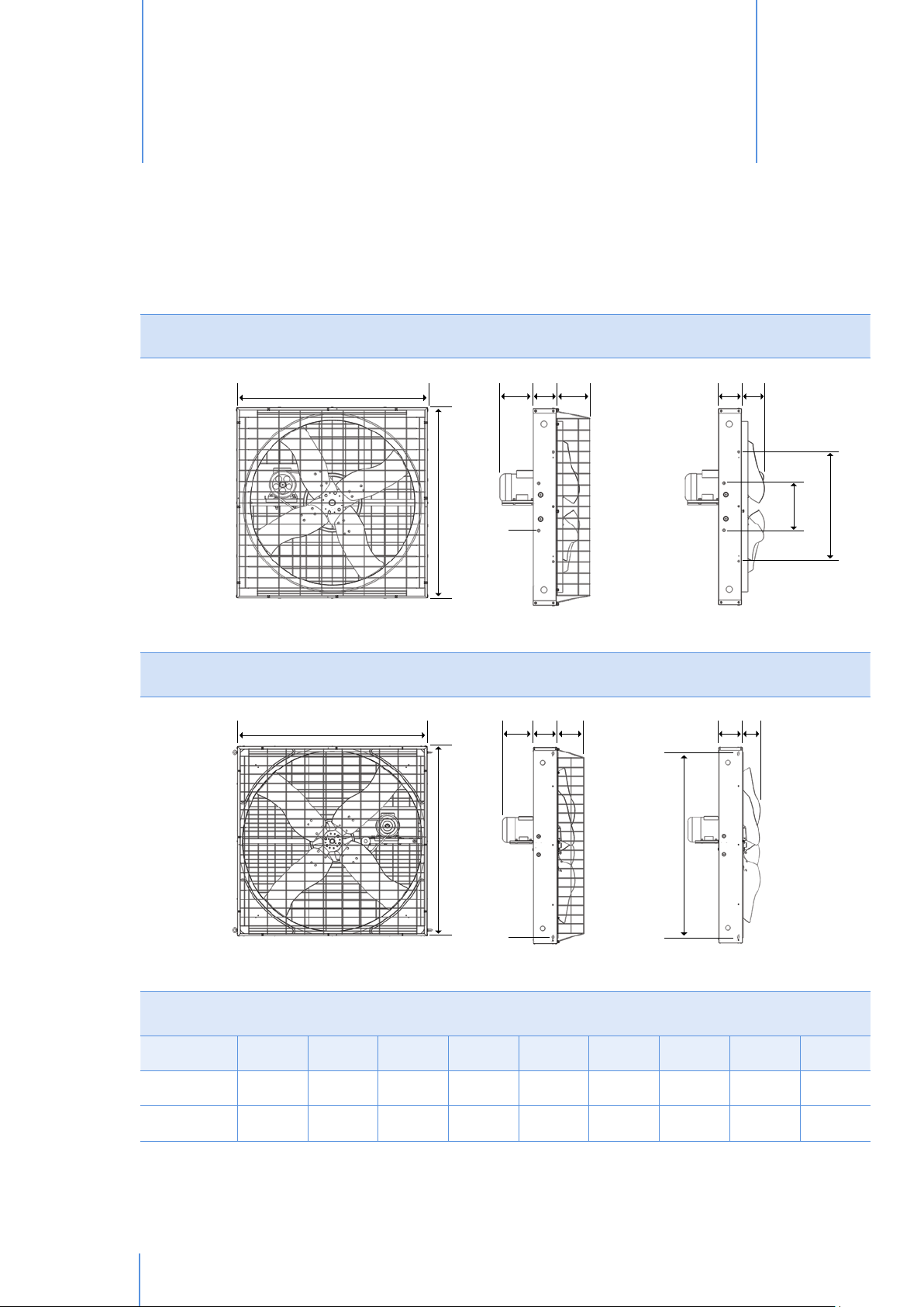
7.1 Dimensions
7.
MFS36
fig.18
A
B
A
CFDDE
MFS52
CFD DE G
G
I
H
B
fig.19
Fan dimensions [mm]
Model A B C D E F G H I
MFS36 1,085 1,085 180* 130 200 M8 130 260 600
MFS52 1,425 1,425 220* 176 190 M8 125 1,330 -
* Distance may vary according to the type motor installed.
22
© Munters AB, 2013
H
Page 23

Technical dataChapter7
fig.20
Mounting kit dimensions for MFS52
1040mm
675mm
7.2 Technical specifications
MFS36 MFS52
0.5hp 0.75hp
1.0 &
1.2hp
Number of blades 4
Propeller diameter mm [inch] 915 [36] 1,320 [52]
Weight of fully equipped fan* [kg] 38 38.5 41.5 43 47
Airflow at 0 Pa
Specific performance at 0 Pa m
3
/h [cfm]
m
3
/h /W [cfm/W]
16,740
[9,853]
33.3
[19.6]
19,770
[11,636]
26.7
[15.7]
21,973
[12,933]
21.6
[12.7]
Max. operating temperature °C [°F] 50 [122]
Nominal propeller speed [rpm] 479 570 636 406 461
1.0 &
1.2hp
37,638
[22,153]
33.5
[19.7]
2.0hp
44,803
[26,370]
25.3
[14.9]
IEC protective class of electric motor IP55
Electric motor winding insulation grade F
*Excludes safety kit for installation below 2.7m above the floor.
© Munters AB, 2013
23
Page 24

Technical dataChapter7
7.3 Motor specifications
Code Nominal Power
[W] [Hp]
a 370 0.5 1 single 50 200/230 3 1,350
b 370 0.5 1 multi 50 200/230 3 1,350
c 370 0.5 1 single 60 208/230 2.9 1,680
d 370 0.5 3 single 50 230/400 2.3/1.3 1,400
e 370 0.5 3 single 60 230/400 2.3/1.3 1,700
f 370 0.5 3 multi 50 230/400 2.4/1.4 1,360
g 370 0.5 3 multi 60 230/400 1.9/1.1 1,630
h 550 0.75 1 single 50 200/230 4.5 1,380
i 550 0.75 1 multi 50 200/230 4.5 1,380
j 550 0.75 1 single 60 208/230 4.4 1,660
k 550 0.75 3 single 50 230/400 2.8/1.6 1,400
l 550 0.75 3 single 60 230/400 2.8/1.6 1,700
Phases Speed Frequency
[Hz]
MFS36
Voltage
[V]
Current
[A]
rpm
m 550 0.75 3 multi 50 230/400 2.9/1.65 1,380
n 550 0.75 3 multi 60 230/400 2.4/1.4 1,630
o 735 1.0 1 single 50 200/230 5.2 1,350
p 735 1.0 1 multi 50 200/230 5.2 1,350
q 735 1.0 1 single 60 208/230 5.6 1,660
r 735 1.0 3 single 50 230/400 3.5/2 1,400
s 735 1.0 3 single 60 230/400 3.5/2 1,700
t 880 1.2 3 multi 50 230/400 4.3/2.5 1,380
u 880 1.2 3 multi 60 230/400 3.8/2.2 1,640
MFS52
a 735 1.0 1 single 50 200/230 5.2 1,350
b 735 1.0 1 multi 50 200/230 5.2 1,350
c 735 1.0 1 single 60 208/230 5.6 1,660
d 735 1.0 3 single 50 230/400 3.5/2 1,400
e 735 1.0 3 single 60 230/400 3.5/2 1,700
24
f 880 1.2 3 multi 50 230/400 4.3/2.5 1,380
g 880 1.2 3 multi 60 230/400 3.8/2.2 1,640
h 1,500 2.0 3 single 50 230/400 6.1/3.5 1,400
i 1,500 2.0 3 single 60 230/400 5.5/3.2 1,680
© Munters AB, 2013
Page 25

Maintenance
8.
8.1 Introduction
Maintenance must only be carried out by qualified personnel only using suitable tools and working methods.
Before any maintenance steps are taken, make sure the power switch is in the off position and locked by a
padlock. Make sure the propeller is at a complete standstill.
WARNING
Fans do not contain parts needing periodic lubrication, as moving parts are either manufactured from self lubricating
materials, or are sealed with lifetime lubrication.
8.2 Cleaning
Inspect the fan at regular intervals and keep it clean. It is advised to perform periodic cleaning of safety mesh
guards. Dust on the safety mesh guards causes extra power consumption; severe dust on the motor can cause
overheating and subsequent motor failure.
WARNING
The capacitor in single-phase motors can retain a charge which appears across
the motor terminals even when the motor has reached standstill.
Keep motor body clean. Dust deposit on motor body will lead to overheating and
failure of bearings and motor itself.
Do not use water for motor cleaning. Use compressed air only. Water spraying
will cause rust inside the bearings and lead to their failure.
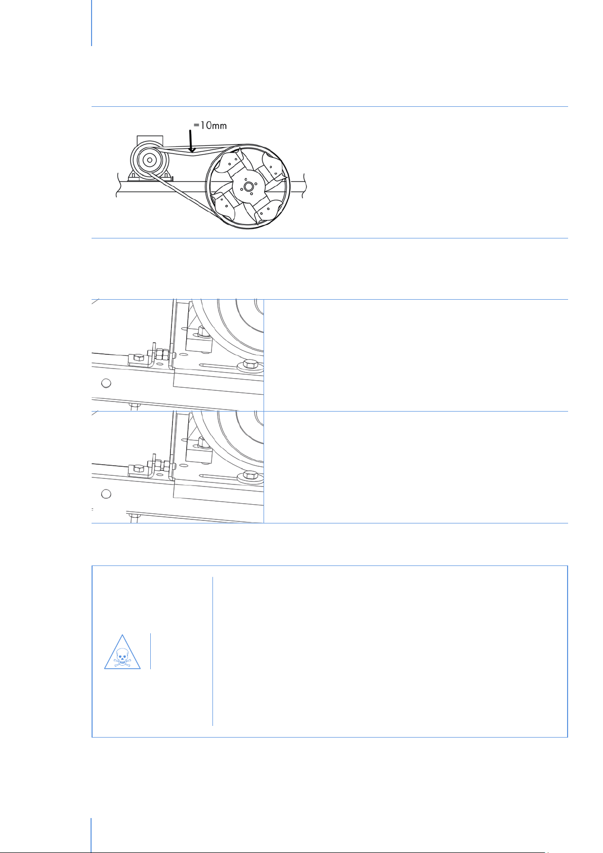
8.3 Belt tensioning check up (without belt tensioner)
Check V-belt tension at regular intervals, the correct tension is obtained when maximum deflection (half-way from
motor and central pulley) is about 10 mm, when pushed in by thumb.
Tighten fan belt after this fan has been running for 3 days. Without adjusting the
WARNING
tension, transmission components can wear out early.
© Munters AB, 2013
25
Page 26
MaintenanceChapter8
fig.21
8.4 Tensioning belt adjuster
To reset the correct tension:
• open the safety mesh guards;
• unscrew motor slide fixing screws (without
removing them);
• using the tensioning belt adjuster instruction
tighten the V-belt by pushing the motor sideways;
• tighten the fixing screws adequately;
• fix the safety meshes guard to the fan housing.
fig.22
WARNING
1. Be sure to adjust the two M6 nuts and the grub screw, in order to
avoid any clearance of it.
2. Tighten the two bolts in the motor plate so that the V-belt remains
in tension.
Do not operate the fan with the safety protections removed: safety meshes can be
removed only with specific tools by qualified technicians when the fan reaches a
complete standstill.
The fixing sytems of the safety protections are not interchangeable with other
devices. Therefore, if for maintenance reasons the user damages or loses any
component, this must be definetely ordered from the manufacturer as spare parts
and it cannot just be replaced with other components, even similar, not supplied
by the manufacturer itself. In this particular event the manufacturer refuses all
responsibility on consequent damages caused to things and people and considers
any kind of warranty lost.
26
© Munters AB, 2013
Page 27
MaintenanceChapter8
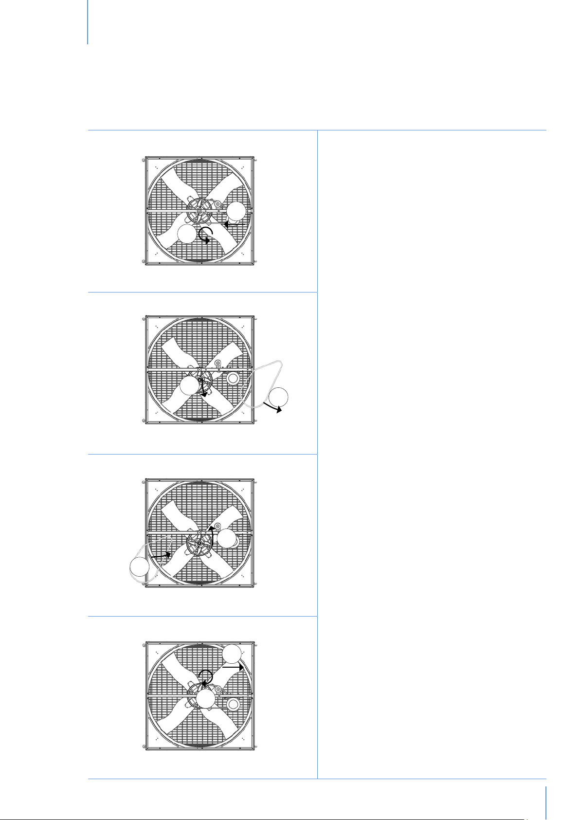
8.5 Replacement of V-belt
1
3
5
2
If the V-belt should be damaged in any way, it has to
be replaced. How to replace the V-belt:
1. open the safety mesh guards and loosen the
bolts of the motor frame; slide the motor frame
towards the centre of the fan to release any
4
6
tension on the V-belt;
2. undo the 25mm hexagonal nut holding the
propeller assembly to fan body;
3. carefully remove the propeller assembly from the
fan body and let it rest on the bottom of the fan
body;
4. remove the old V-belt;
5. insert the new V-belt.
6. replace the propeller assembly into the fan body;
7. fasten the 25mm hexagonal nut onto the shaft of
the propeller assembly;
8. tighten the V-belt by pushing the motor away
from the centre of the fan and then tighten the
bolts on the motor frame.
fig.23
8
7
© Munters AB, 2013
27
Page 28

MaintenanceChapter8
8.6 Fan bearing lubrication
Bearings are properly sized, with double sealed protection (2RS) and lubricated for life, therefore they do not
require any additional lubrication.
8.7 Propeller replacement
If damage occurs to the propeller,
it is necessary to replace the whole
propeller because of the difficulty to
balance it in the field. How to replace
the propeller:
1. remove the pyramidal safety mesh
and unscrew the four M8 bolts
holding the propeller to the fan;
2. remove the propeller;
3. insert the new propeller;
4. tighten the four M8 bolts holding
the propeller to the fan and reinstall the pyramidal safety mesh.
28
fig.24
© Munters AB, 2013
Page 29
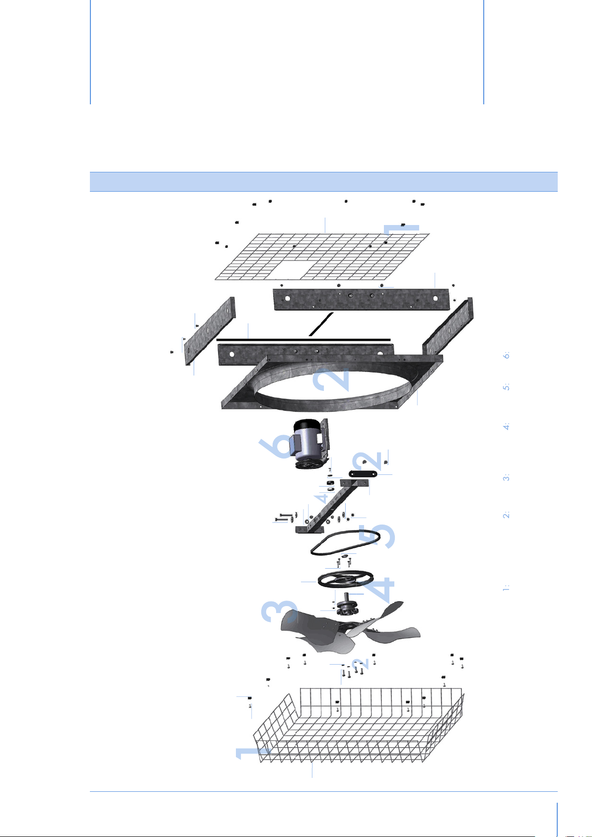
Spare part list
9.
MFS36
1.4
2.15
2.16
2.14
2.17
2.18
2.19
Motor
Belt
2.20
Pulley
2.8
2.7
2.6
4.7
2.5
2.4
2.3
4.3
2.13
4.5
4.4
4.2
4.1
2.9
Propeller
2.10
2.11
Body
2.12
Safety Meshes
4.6
fig.25
1.3
1.2
© Munters AB, 2013
GROUPS
2.2
2.1
1.1
29
Page 30

Spare part listChapter9
REF. DESCRIPTION QUANTITY
GROUP 1: SAFETY MESHES
1 KIT SAFETY MESHES 1
1.1 PYRAMIDAL SAFETY MESH 1,333.5X1,333.5 121X61 GALV. 1
1.2 SELF TAPPING SCREW 6,3X19 GALV. 24
1.3 PLASTIC CLIP FOR MESH 24
1.4 REAR SAFETY MESH 1,045.5X1,045.5 M74.5X74.5 GALV. 1
GROUP 2: BODY
2 GALV. FRAME 1
2.1 HEXAGON BOLT M8X30 8,8 UNI 5739 GALV. 4
2.2 PLAIN WASHER D8,4X15 UNI 6798 4
2.3 HEXAGON BOLT M8X65 8.8 UNI 5737 GALV. 2
2.4 EXTERNALLY THOOTED WASHER D10,5X18 UNI 5589 4
2.5 TICK HEXAGON NUT M10X10 UNI 5587 GALV. 4
2.6 CUP COVER NUT 1
2.7 LARGE PLAIN WASHER D6,7X24 UNI 659 1
2.8 SELF TAPPING SCREW 6,3X19 GALV. 1
2.9 HEXAGON SOCKET SCREW M10X30 10.9 UNI 5933 4
2.10 OVAL PLATE 2
2.11 CENTRAL SUPPORT GALV. 1
2.12 TICK HEXAGON NUT M8X8 UNI 5587 GALV. 6
2.13 LARGE PLAIN WASHER D8X32 DIN 126 4
2.14 TOP/BOTTOM PANEL 1,133X194X0,6 GALV. 2
2.15 POP RIVET D4,8X7 12
2.16 LONG THREADED BUSH D8X17,5 M8 GALV. 8
2.17 EPDM STRIP 15X3mm 3,3m
2.18 HEXAGON THREADED BUSH M8 4
2.19 SIDE PANEL 1,078X194X1 GALV. 2
2.20 VENTURI GALV. 1
2.21 EUROEMME STICKER18X131 1
30
2.22 STICKER NO HIGH PRESSURE 42X118 2
2.23 STICKER 95X115 2
2.24 WARNING STICKER B-1997 70X105 2
GROUP 3: PROPELLER
3 PROPELLER INOX/GALV. 1
GROUP 4: PULLEY
4 CENTRAL PULLEY 1
4.1 TICK HEXAGON NUT M6X6 UNI 5587 GALV. 4
4.2 PLAIN WASHER D6,4X12,5 UNI 659 4
4.3 CENTRAL PULLEY DP325X1A 1
© Munters AB, 2013
Page 31
Spare part listChapter9
4.4 HEXAGON BOLT M6X30 8,8 UNI 5739 GALV. 4
4.5 WATERPROOF DISTANCE PIECE 1
4.6 HUB 1
4.7 THIN HEXAGON NUT M25X10 UNI 5589 1
GROUP 5: BELT
5 V-BELT A53 1
GROUP 6: MOTOR
6 SEE MOTOR TABLE 1
GROUP 7: KIT OPZIONALI
7A CHAIN SUSPENSION KIT 1
7B WALL/COLUMN MOUNTING SYSTEM 1
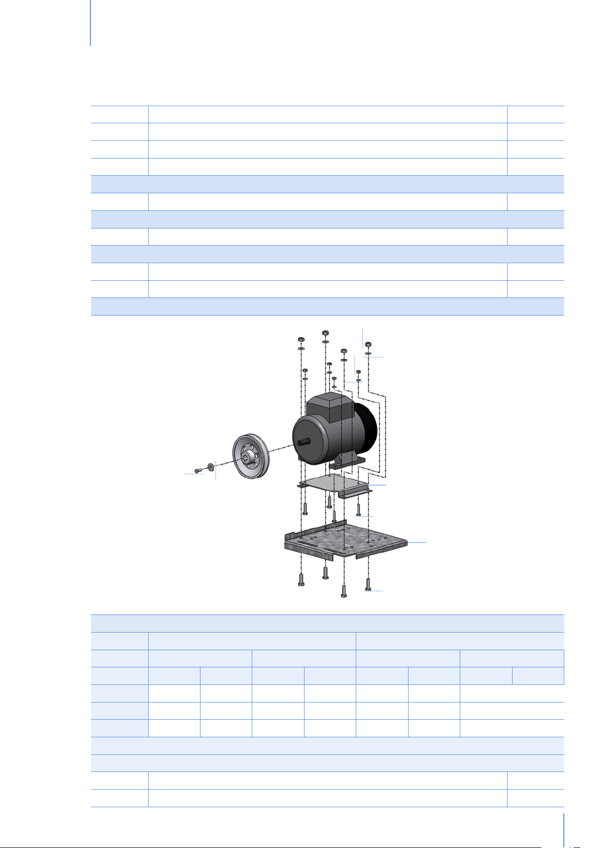
MOTOR
1
3*
4*
9
10
2
5*
6
7
8
fig.26 *only for 0.5/0.75 Hp motors
MOTOR PULLEY PITCH DIAMETER AND HOLE
3-PHASE SINGLE PHASE
ONE SPEED MULTI SPEED ONE SPEED MULTI SPEED
50 HZ 60 HZ 50 HZ 60 HZ 50 HZ 60 HZ 50 HZ 60 HZ
HP0.5 PD110 H14 PD90 H14 PD110 H14 PD90 H14 PD110 H19 PD90 H14 PD110 H19 -
HP0.75 PD130 H14 PD105 H14 PD130 H14 PD105 H14 PD130 H19 PD105 H19 PD130 H19 -
HP1.0 PD150 H19 PD125 H19 PD150 H19 PD125 H19 PD150 H19 PD125 H19 PD150 H19 -
BOLTS&NUTS
MODELS HP0.5/0.75 - 50/60HZ
1 TICK HEXAGON NUT M8X8 UNI 5587 GALV. 4
2 PLAIN WASHER D8,4X17 UNI 659 4
© Munters AB, 2013
31
Page 32

Spare part listChapter9
3 TICK HEXAGON NUT M6X6 UNI 5587 GALV. 4
4 PLAIN WASHER D6,4X12,5 UNI 659 4
5 MOTOR PLATE ADAPTOR FOR MEC71 200X119X2 1
6 HEXAGON BOLT M6X25 8,8 UNI 5739 GALV. 4
7 MOTOR PLATE 222X244X3 GALV. 1
8 HEXAGON BOLT M8X25 8,8 UNI 5739 GALV. 4
9 HEXAGON BOLT M5X16 8,8 UNI 5739 GALV. 1
10 PLAIN WASHER D5X20 GALV. 1
MODELS HP1.0 - 50/60HZ
1 TICK HEXAGON NUT M8X8 UNI 5587 GALV. 4
2 PLAIN WASHER D8,4X17 UNI 659 4
7 MOTOR PLATE 222X244X3 GALV. 1
8 HEXAGON BOLT M8X25 8,8 UNI 5739 GALV. 4
9 HEXAGON BOLT M6X20 8,8 UNI 5739 GALV. 1
10 PLAIN WASHER D6,7X24 UNI 659 1
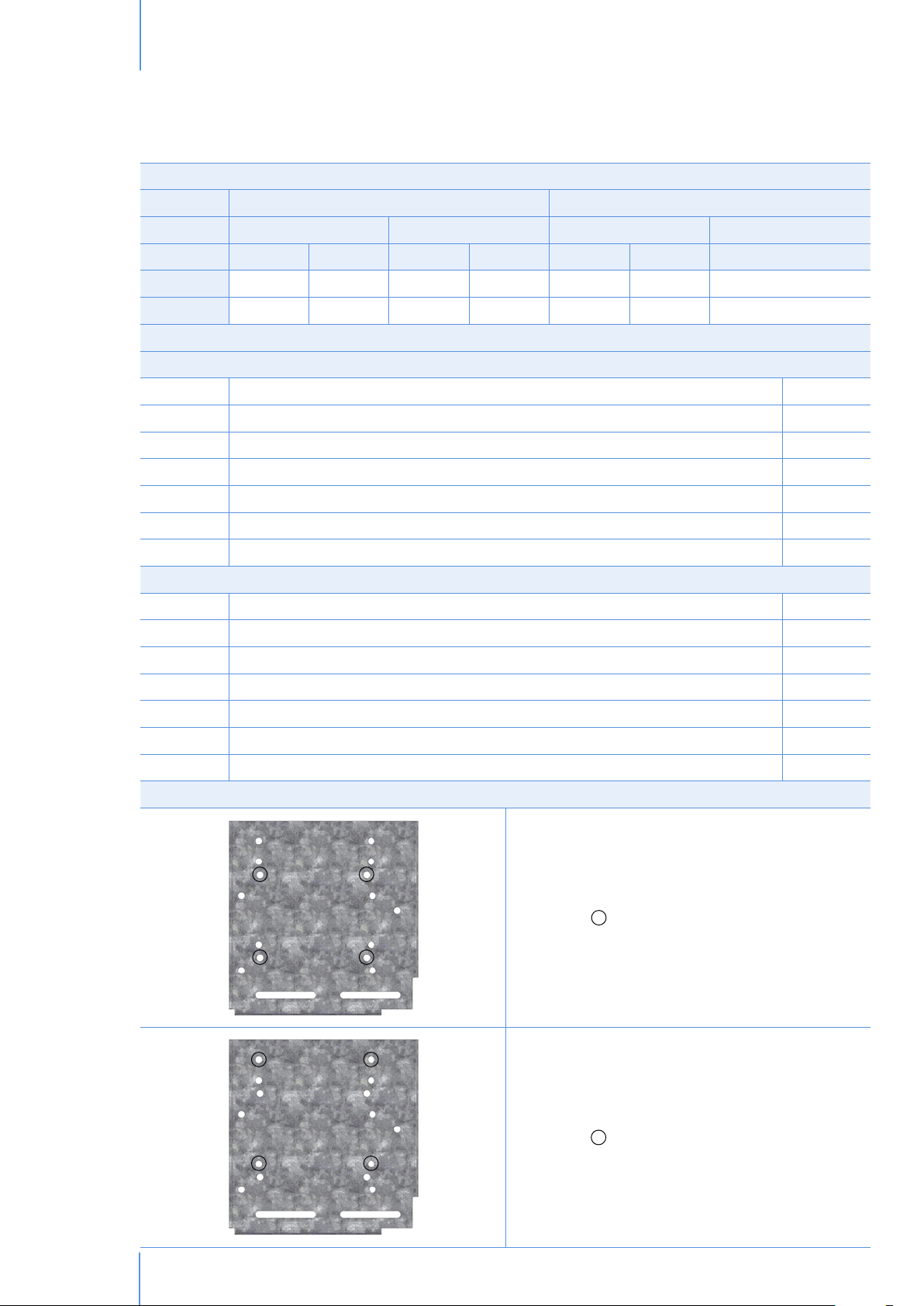
HOLES FOR MOTOR
= HOLES FOR 0.5HP MOTORS
= HOLES FOR 0.75HP MOTORS
32
= HOLES FOR 1.0HP MOTORS
fig.27
© Munters AB, 2013
Page 33

Spare part listChapter9
MFS52
1.5
1.4
1.6
2.22
Motor
2.21
2.23
Belt
2.19
2.20
2.24
2.11
2.9
2.10
2.7
4.7 2.5
2.4
2.3
2.18
4.1
2.17
4.2
2.8
2.6
2.13
2.12
2.14
2.15
2.16
4.3
4.4
4.5
4.6
Pulley
Propeller
Body
Safety Meshes
GROUPS
2.2
2.1
1.3
1.2
fig.28
1.1
REF. DESCRIPTION QUANTITY
GROUP 1: SAFETY MESHES
1 KIT SAFETY MESHES 1
1.1 PYRAMIDAL SAFETY MESH 1665X1660 126X66 GALV. 1
© Munters AB, 2013
33
Page 34

Spare part listChapter9
1.2 SELF TAPPING SCREW 6,3X19 GALV. 32
1.3 PLASTIC CLIP FOR MESH 28
1.4 REAR SAFETY MESH 685X1,390 126X62 1
1.5 CENTRAL CLIP FOR MESH 2
1.6 REAR SAFETY MESH 685X1,390 126X62 MOTORSIDE 1
GROUP 2: BODY
2 GALV. FRAME 1
2.1 HEXAGON BOLT M8X30 8,8 UNI 5739 GALV. 4
2.2 PLAIN WASHER D8,4X15 UNI 6798 6
2.3 TICK HEXAGON NUT M8X8 UNI 5587 GALV. 6
2.4 SPRING WASHER D6,4X11,4 1
2.5 CUP COVERNUT 1
2.6 PLAIN WASHER D6,7X24 GALV.+SEALANT 1
2.7 SELF TAPPING SCREW 6,3X19 GALV. 1
2.8 OVAL PLATE 2
2.9 HEXAGON SOCKET SCREW M10X30 UNI 5933 4
2.10 CENTRAL SUPPORT GALV. 1
2.11 PLAIN WASHER D10,5X18 UNI 5589 4
2.12 TICK HEXAGON NUT M10X10 UNI 5587 GALV. 4
2.13 GRUB SCREW M6X30 UNI 5923 GALV. 1
2.14 HEXAGON BOLT M6X60 8,8 GALV. 1
2.15 L STAFF FOR BELT TENSIONER 1
2.16 HEXAGON BOLT M8X65 8.8 UNI 5737 GALV. 2
2.17 TICK HEXAGON NUT M6X6 ALTO 5587 GALV. 3
2.18 PLAIN WASHER D8X32 DIN 126 4
2.19 POP RIVET D4,9X7 GALV. 24
2.20 HEXAGON THREADED BUSH M8 8
2.21 EPDM STRIP 15X3mm 5m
2.22 SIDE PANEL DX/SX 1,420X175.5X0.8 GALV. 2
2.23 TOP/BOTTOM PANEL 1,420X175.5X0.8 GALV. 2
34
2.24 VENTURI GALV. 1
2.25 EUROEMME STICKER 18X131 1
2.26 EUROEMME STICKER 24,6X180 1
2.27 STICKER NO HIGH PRESSURE 42X118 2
2.28 STICKER 95X115 1
2.29 WARNING STICKER 70X105 2
GROUP 3: PROPELLER
3 PROPELLER INOX/GALV. 1
GROUP 4: PULLEY
4 CENTRAL PULLEY 1
© Munters AB, 2013
Page 35

Spare part listChapter9
4.1 PLAIN WASHER D6,4X12,5 UNI 659 4
4.2 WATERPROOF DISTANCE PIECE 1
4.3 HEXAGON BOLT M6X30 8,8 UNI 5739 GALV. 4
4.4 CENTRAL PULLEY DP325X1A 1
4.5 HUB 1
4.6 TICK HEXAGON NUT M6X6 UNI 5587 GALV. 4
4.7 THIN HEXAGON NUT M25X10 UNI 5589 1
GROUP 5: BELT
5 V-BELT A61-1510 1
GROUP 6: MOTOR
6 SEE MOTOR TABLE 1
GROUP 7: OPTIONAL KITS
7A CHAIN SUSPENSION KIT 1
7B WALL/COLUMN MOUNTING SYSTEM 1
7C TENSIONER 1
7C1 PLASTIC ADAPTOR FOR BELT TENSIONER 1
7C2 SPRING WASHER D10.5 UNI 8842A 1
7C3 HEX BOLT M10X90X26N ISO 4014 1
MOTOR
1
2
6
5
7
fig.29
© Munters AB, 2013
3
4
35
Page 36
Spare part listChapter9
MOTOR PULLEY PITCH DIAMETER AND HOLE
3-PHASE SINGLE PHASE
ONE SPEED MULTI SPEED ONE SPEED MULTI SPEED
50 HZ 60 HZ 50 HZ 60 HZ 50 HZ 60 HZ 50 HZ 60 HZ
HP1.0 PD90 H19 PD75 H19 PD90 H19 PD75 H19 PD90 H19 PD75 H19 PD90 H19 -
HP2.0 PD106 H24 PD90 H24 - - - - - -
BOLTS&NUTS
MODELS HP1.0 - 50/60HZ
1 TICK HEXAGON NUT M8X8 UNI 5587 GALV. 4
2 PLAIN WASHER D8,4X17 UNI 659 4
3 MOTOR PLATE 234X228X3 GALV. 1
4 HEXAGON BOLT M8X25 8,8 UNI 5739. 4
5 HEXAGON BOLT M6X20 8,8 UNI 5739 1
6 SPRING WASHER D6,4X11,4 UNI 1751 1
7 PLAIN WASHER D6,7X24 UNI 659 1
MODELS HP2.0 - 50/60HZ
1 TICK HEXAGON NUT M8X8 UNI 5587 GALV. 4
2 PLAIN WASHER D8,4X17 UNI 659 4
3 MOTOR PLATE 234X228X3 GALV. 1
4 HEXAGON BOLT M8X25 8,8 UNI 5739. 4
5 HEXAGON BOLT M8X20 8,8 UNI 5739 1
6 SPRING WASHER D8,4X14,4 UNI 1751 1
7 PLAIN WASHER D8X32 DIN 126 1
HOLES FOR MOTOR
= HOLES FOR 1.0HP MOTORS
36
= HOLES FOR 2.0HP MOTORS
fig.30
© Munters AB, 2013
Page 37

Warranty
10.
Warranty and technical assistance
Munters products are designed and built to provide reliable and satisfactory performance but cannot be guaranteed
free of faults; although they are reliable products they can develop unforeseenable defects and the user must take
this into account and arrange adequate emergency or alarm systems if failure to operate could cause damage to
the articles for which the Munters plant was required: if this is not done, the user is fully responsible for the damage
which they could suffer.
Munters extends this limited warranty to the first purchaser and guarantees its products to be free from defects
originating in manufacture or materials for one year from the date of delivery, provided that suitable transport,
storage, installation and maintenance terms are complied with. The warranty does not apply if the products have
been repaired without express authorisation from Munters, or repaired in such a way that, in Munters’ judgement,
their performance and reliability have been impaired, or incorrectly installed, or subjected to improper use. The
user accepts total responsibility for incorrect use of the products.
The warranty on products from outside suppliers fitted to MFS, (for example electric motors, belts, etc.) is limited
to the conditions stated by the supplier: all claims must be made in writing within eight days of the discovery of
the defect and within 12 months of the delivery of the defective product. Munters has thirty days from the date of
receipt in which to take action, and has the right to examine the product at the customer’s premises or at its own
plant (carriage cost to be borne by the customer).
Munters at its sole discretion has the option of replacing or repairing, free of charge, products which it considers
defective, and will arrange for their despatch back to the customer carriage paid. In the case of faulty parts of
small commercial value which are widely available (such as bolts, etc.) for urgent despatch, where the cost of
carriage would exceed the value of the parts, Munters may authorise the customer exclusively to purchase the
replacement parts locally; Munters will reimburse the value of the product at its cost price.
Munters will not be liable for costs incurred in demounting the defective part, or the time required to travel to site
and the associated travel costs. No agent, employee or dealer is authorised to give any further guarantees or to
accept any other liability on Munters’ behalf in connection with other Munters products, except in writing with the
signature of one of the Company’s Managers.
In the interests of improving the quality of its products and services, Munters
WARNING
The liability of the manufacturer Munters ceases in the event of:
• dismantling the safety devices;
• use of unauthorised materials;
• inadequate maintenance;
• use of non-original spare parts and accessories.
reserves the right at any time and without prior notice to alter the specifications
in this manual.
© Munters AB, 2013
37
Page 38

WarrantyChapter10
Barring specific contractual terms, the following are directly at the user’s expense:
• preparing installation sites;
• providing an electricity supply (including the protective equipotential bonding (PE) conductor, in accordance
with CEI EN 60204-1, paragraph 8.2), for correctly connecting the equipment to the mains electricity
supply;
• providing ancillary services appropriate to the requirements of the plant on the basis of the information
supplied with regard to installation;
• tools and consumables required for fitting and installation;
• lubricants necessary for commissioning and maintenance.
It is mandatory to purchase and use only original spare parts or those recommended by the manufacturer.
Dismantling and assembly must be performed by qualified technicians and according to the manufacturer’s
instructions.
The use of non-original spare parts or incorrect assembly exonerates the manufacturer from all liability.
Requests for technical assistance and spare parts must be made directly to the manufacturer, at the following
address:
Munters Italy S.p.A
Strada Piani, 2
18027 Chiusavecchia (IM), Italy
Tel: +39 0183 52 11
Fax: +39 0183 521 333
38
© Munters AB, 2013
Page 39

Euroemme® MFS circulation fan is developed and produced by Munters Italy S.p.A., Italy
is a trademark of Munters AB
®
www.munters.com
Australia Munters Pty Limited, Phone +61 2 8843 1594, Brazil Munters Brasil Industria e Comercio Ltda, Phone +55 41 3317 5050, Canada Munters Corporation
Mason, Phone +1 517 676 7070, China Munters Air Treatment Equipment (Beijing) Co. Ltd, Phone +86 10 80 481 121, Denmark Munters A/S, Phone
+45 9862 3311, India Munters India, Phone +91 20 3052 2520, Indonesia Munters, Phone +62 818 739 235, Italy Munters Italy S.p.A., Chiusavecchia,
Phone +39 0183 52 11, Japan Munters K.K., Phone +81 3 5970 0021, Korea Munters Korea Co. Ltd., Phone +82 2 761 8701, Mexico Munters Mexico, Phone
+52 818 262 54 00, Russia Munters AB, Phone +7 812 448 5740, Singapore Munters Pte Ltd., Phone +65 744 6828, South Africa and Sub-Sahara Countries
Munters (Pty) Ltd., Phone +27 11 997 2000, Spain Munters Spain S.A., Phone +34 91 640 09 02, Sweden Munters AB, Phone +46 8 626 63 00, Thailand
Munters Co. Ltd., Phone +66 2 642 2670, Turkey Munters Form Endüstri Sistemleri A.Ş, Phone +90 322 231 1338, USA Munters Corporation Mason, Phone
+1 517 676 7070, Vietnam Munters Vietnam, Phone +84 8 3825 6838, Export & Other countries Munters Italy S.p.A., Chiusavecchia Phone +39 0183 52 11
© Munters AB, 2013
Ag/MIT/UmGB-2085-04/13 rev1.1 Euroemme
 Loading...