

Page 1
Operator’s Manual
JAZ
GB
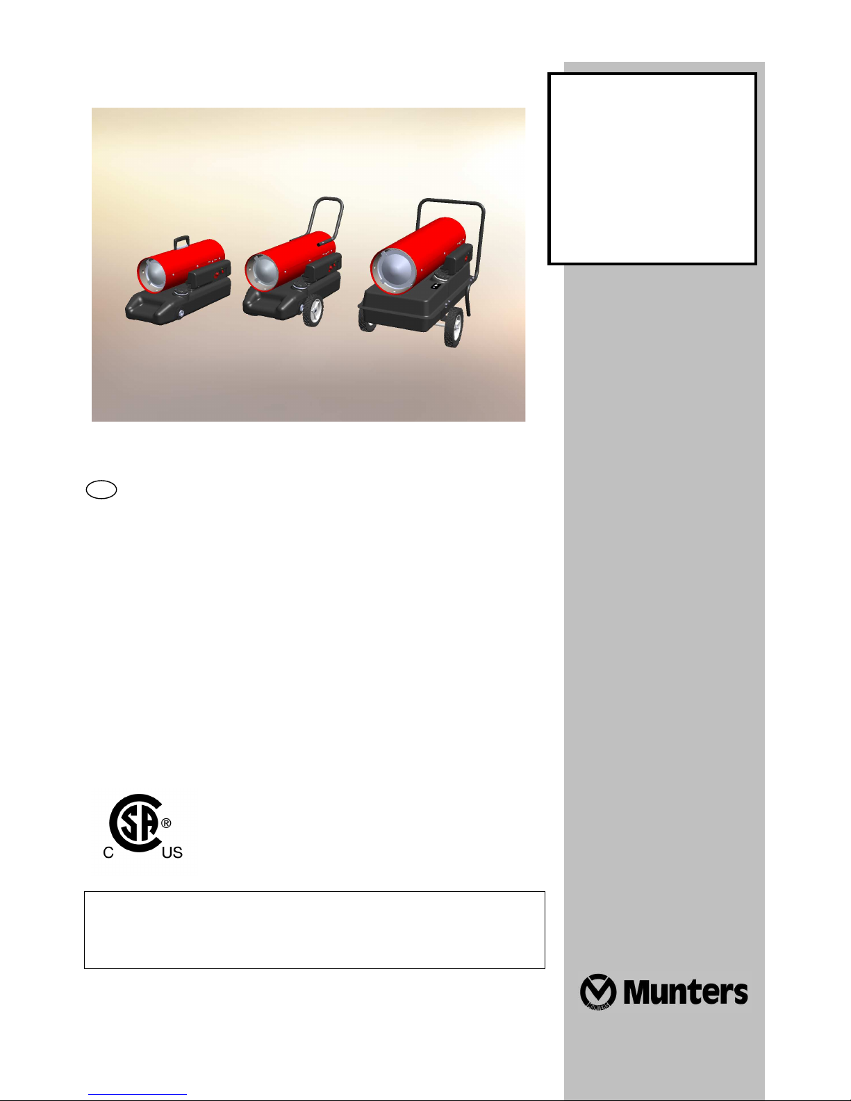
Direct-fired
Diesel/Kerosene Air Heaters
JAZ 42
JAZ 80
JAZ 80 W
JAZ 125
JAZ 160
IMPORTANT: Read and understand this manual before
assembling, starting or servicing the heater. Improper use
of this heater can cause serious injury. Keep this manual
for future reference.
1
Page 2

Introduction
Thank you for choosing a Munters product. Read this manual carefully before using the unit and save it
for future reference.
Disclaimer
Munters reserves the right to make alterations to specifications, quantities, dimensions etc. for production
or other reasons, subsequent to publication.
While we believe the information is accurate and complete, we make no warranty or representation for
any particular purposes. The information is offered in good faith and with the understanding that any use
of the units or accessories in breach of the directions and warnings in this document is at the sole
discretion and risk of the user.
2
Page 3

1. General Safety Information
This is the safety alert symbol. It alerts you to
potential personal injury hazards. Strictly
obey all safety messages that follow this
symbol.
Indicates a hazardous situation, which, if not
avoided, will result in death or serious injury.
Indicates a hazardous situation, which, if not
avoided, could result in death or serious
injury.
Indicates a hazardous situation, which, if not
avoided, could result in minor or moderate
injury.
Failure to comply with the precautions and
instructions provided with this heater, can
result in death, serious bodily injury and
property loss or damage from hazards of fire,
explosion, burn, asphyxiation, carbon
monoxide poisoning, and/or electrical shock.
Only persons who can understand and follow
the instructions should use or service this
heater.
living areas or in non-adequately ventilated
enclosed spaces.
may lead to death.
explosion hazard. Keep solid combustibles,
such as building materials, paper or
cardboard, a safe distance away from the
heater as recommended by the instructions.
Never use the heater in spaces which do or
may contain volatile or airborne
combustibles, or products such as gasoline,
solvents, paint thinner, dust particles or
unknown chemicals.
or other flammable vapors and liquids in the
vicinity of this or any other appliance.
General Hazard Warning
Not for use in residential
Carbon monoxide poisoning
Fire, burn, inhalation, and
Do not store or use gasoline
Not for home or recreational
vehicle use
Local laws and regulations may limit or
prohibit the use of this type of heater.
Consult your local fire department for further
information.
Combustion by-products
produced when using this product contain
carbon monoxide, a chemical known to the
State of California to cause cancer and birth
defects or other reproductive harm.
Massachusetts Residents: Massachusetts
state law prohibits the use of this heater in
any building which is used in whole or in part
for human habitation. Use of this heating
device in Massachusetts requires local fire
department permit (M.G.L.C. 148, Section
10A).
New York City Residents: The New York City
fire Code prohibits the storage, handling and
use of kerosene fueled heaters for space
heating. Any person violating that provision
may be punished by a fine up to $10,000 and
a term of imprisonment up to 6 months.
The heater surfaces become
very hot during and after operation. Do not
touch! Use personal protecting equipment if
needed.
Children should be
supervised to ensure that they do not play
with the heater.
This heater is not intended for
use by persons (including children) with
reduced physical, sensory or mental
capabilities, or lack of experience and
knowledge.
Shut off and unplug the
heater before moving it. Never pull the cable
to unplug or move the unit.
Never leave the heater
unattended while burning or connected to a
power source.
3
Page 4
1
Never use or touch the heater
with wet hands or when either the heater or
the power cable is wet.
2. Product Description
This is a Diesel or Kerosene-Fueled, direct-fired air
heater. It is primarily intended for temporary
heating of buildings under construction, alteration
ordinances and codes when using this
heater.
or repair. Direct-fired means that the combustion
products of the heater enter the heated space. This
appliance produces small amounts of carbon
monoxide. Carbon monoxide is toxic.
Follow all state and local
3. Technical Specifications
Model JAZ 42 JAZ 80 JAZ 80 W JAZ 125 JAZ 160
Heat Input [BTU/hr] 40,000 77,700 77,700 125,000 160,000
Air Flow Rating [ft³/min] 180 335 335 420 480
Fuel Type No.1 Fuel Oil (Diesel Fuel) / No.2 Fuel Oil (Diesel Fuel) / Kerosene
Fuel consumption [gal/h] 0.28 0.56 0.56 0.92 1.16
Fuel Nozzle Size 0.30 gph 0.65 gph 0.65 gph 0.85 gph 1.00 gph
Voltage 120V 60Hz
Electrical Power [W] 180 230 230 240 430
Air Pressure Setting [psi] 4.8 4.1 4.1 5.1 5.5
Current Rating [A] 1.50 2.00 2.00 2.05 3.15
Fuse rating [A] T 4A T 4A T 4A T 4A T 4A
Dimensions
Net Weight [lb] 27.3 30.4 34.6 58.9 62.2
ength [in] 26.4 26.4 32.0 36.6 36.6
Width [in] 12.5 12.5 17.7 20.5 20.5
Height [in] 16.5 16.5 24.4 25.0 25.0
Tank Capacity [gal] 5.0 5.0 5.0 11.4 11.4
Running Time [h] ~18 ~9 ~9 ~13 ~10
Standard Features
Fuel Level Indicator Sightglass Sightglass Sightglass Fuel gauge Fuel gauge
Power Cord Support yes yes yes yes yes
Handle top top rear rear + front rear + front
Ambient Thermostat built-in built-in built-in built-in built-in
Error Indicator built-in built-in built-in built-in built-in
4. Assembling Instructions
Remove the heater from its shipping carton. If
the unit is damaged in anyway, do not use it and
contact your dealer.
4
JAZ 42/JAZ 80: the heater is fully assembled -
no further assembly required
JAZ 80 W
The following parts are supplied with the heater
in the shipping carton.
4
Page 5

6 Washer D.5
4
6 Screw M5x16*
4
9 End cap
2
Fig. 1
Before adding fuel, installation and use,
assemble the loose parts as follows (see Fig. 1):
Fix end caps (2) to handle (1). Remove upper
cover (3) unscrewing six fixing screws (4).
Assemble handle to upper shell using four
screws (5), washers (6) and nuts (7).
Reassemble upper shell with the six screws (4).
JAZ 125
List of contents
# Description Qty
1 Handle 1
2 End cap 2
3 Upper shell 1
4 Screw M5×8 6
5 Screw M5×30 4
7 Nut M5 4
8 Axle 1
9 Washer 2
10 Spacer 4
11 Wheel 2
12 Cap nut 2
13 Knurled nut 1
14 Support bracket 1
Slide axle (8) through the two tubes on the tank
bottom. Slide spacer (10), washer (9), and
spacer (10) on each axle side. Insert wheels
(11), and cap nut (12). Tap gently on cap nuts to
secure them. Attach support bracket (14)
screwing the knurled nut (13) to the tank drain
cap. Finger tighten firmly.
List of contents
# Description Qty
1 Axle 1
2 Axle bracket 2
3 Spacer 2
4 Wheel D.200 2
5 Cap nut 2
Fig. 2
Before adding fuel, installation and use,
assemble the loose parts as follows (see Fig. 2):
Slide axle (1) through axle brackets (2).
Assemble in order: spacers (3), wheels (4), cap
nuts (5) on each end. Secure cap nuts (5) by
tapping lightly with a hammer. Connect axle
assembly to tank and front handle (11) using four
7 Washer D.5 12
8 Nut M5 12
10 Rear handle 1
11 Front handle 1
12 Screw M5x30 8
* not used on JAZ 125
screws M5x30 (12), washers (7) and nuts (8)
lining up the holes.
Insert end caps (9) on rear and front handle (10)
(11). Connect rear handle (10) to heater tank
using four screws M5x30 (12), washers (7) and
nuts (8) as shown.
2
Page 6

JAZ 160
8 Nut M5
12
List of contents
# Description Qty
1 Axle 1
2 Axle bracket 2
3 Spacer 2
4 Wheel D.200 2
5 Cap nuts 2
6 Screw M5x16 4
7 Washer D.5 12
9 End cap 2
10 Rear handle 1
11 Front handle 1
12 Screw M5x30 8
Fig. 3
Before installation and use, assemble the loose
parts as follows (see Fig. 3):
Slide axle (1) through axle brackets (2).
Assemble in order: cap nuts (3), wheels (4),
spacers (5) on each ends, by tapping lightly.
Connect axle assembly to heater tank using four
screws M5x16 (6), washers (7) and nuts (8).
Insert end caps (9) on rear and front handle (10)
(11). Connect rear handle (10) and front handle
(11) to heater tank using screws M5x30 (12),
washers (7) and nuts (8) as shown.
Tools needed:
- Phillips screwdriver
- Adjustable wrench
- Hammer
5. Electrical Connection and
Installation
Never use this heater in living
or sleeping areas.
Do not cover the heater. Do
not block the air inlet and outlet.
Do not attach ducting to this
heater.
Install the heater upright on a flat, level surface.
1. Provide adequate clearance to combustible
materials.
MINIMUM SAFETY CLEARANCES FROM
MATERIALS (INCLUDING COMBUSTIBLE
MATERIALS) AND OBJECTS IN THE
SURROUNDINGS OF THE HEATER:
Sides: 2 ft
Air inlet: 3 ft
Top: 5 ft
Hot air outlet: 10 ft
Floor: 0 ft
2. Provide adequate ventilation.
Direct-fired heaters are
intended for use in outdoor open areas or in
indoor well ventilated areas. For indoor use,
a minimum opening area to the outside of 3
ft2 per U.S. gallon capacity at the unit level
must be provided, allowing a continuous
fresh air circulation from the outside.
Model
No.
Minimum
Opening
Area
42 80 80 W 125 160
0.84
ft²
1.68
ft²
1.68
ft²
2.76
ft²
3.48
ft²
Carbon monoxide poisoning
may lead to death.
Direct-fired heaters may
cause carbon monoxide (CO) poisoning when
2
Page 7

incorrectly used (e.g indoors without
adequate air circulation) or not properly
working. CO poisoining may lead to death.
Early signs of CO poisoning are headache,
dizziness and/or nausea. If you have these
signs, get fresh air at once, shut off the
heater and check the heater operation and
installation. Call qualified service if needed.
Some people such as pregnant women,
persons with heart or lung diseases, or under
the influence of alcohol, or at high altitudes
are more affected by carbon monoxide than
others.
Connect the power cord female connector to the
male connector on the control panel (see Fig. 4).
1. Fill the fuel tank with clean 1-K Kerosene, Fuel
Oil (Diesel Fuel) No.1 or Fuel Oil (Diesel Fuel)
No.2.
JAZ 42/80/80W: the sightglass on the right side
of the tank allows the user to see when fuel level
is getting low (see Fig. 5)
JAZ 125/160: the fuel gauge on top of the tank
allows the user to see the fuel level during
operation (see Fig. 6)
Fig. 5
Fig. 4
3. Operation with portable generators:
If the heater is powered by a
portable generator, before use:
a. check and be sure that the generator is
properly grounded to earth. Refer to the
generator manual for grounding procedures.
b. check and be sure that the electrical ratings of
the generator are consistent with the electrical
ratings of the heater. Refer to data plates.
c. measure the actual output voltage from the
generator: the voltage must be 120 V +/- 10%
(108 V - 132V). Do not connect the heater to
the generator if the voltage is not within this
range.
The installation of the equipment shall be in
accordance with the regulations of
authorities having jurisdiction and CSA B139.
Do not connect the heater to
external fuel tanks.
6. Operation
Fig. 6
3. Turn the thermostat knob fully
counterclockwise.
4. Plug the heater into a 120V/60Hz, 1 Phase
GFCI protected grounded outlet.
The electrical connections
and grounding of the heater shall be in
compliance with the National Electrical Code,
ANSI/NFPA 70 or the CSA C22.1, Canadian
Electric Code, Part I.
Always check power cables
and extensions before use. Do not use the
heater if any cable is damaged.
IMPORTANT: extensions must be approved,
grounded, 3-wire cords of proper size.
Extension cord size requirements:
6-10 ft 18 AWG (0.75 mm²)
11-100 ft 16 AWG (1 mm²)
101-200 ft 14 AWG (1.5 mm²)
2
Page 8

Fig. 7
To Start the Heater
1. Turn the ON/OFF switch (3) to the ON (“I”)
position. The green indicator light above the
On/Off switch will flash slowly (every 3 seconds),
indicating STAND-BY MODE.
2. Turn the thermostat knob slowly clockwise
until the heater starts. The green indicator light
above the On/Off switch will remain lit
continuously, ON MODE.
3. Adjust the thermostat to the desired
temperature [setting/position?]. One or two
adjustments may be required to obtain the
desired temperature.When the thermostat
senses the temperature has been reached, the
heater will cycle off and return to STAND-BY
MODE. The thermostat will cause the heater to
automatically turn on and off to maintain the set
temperature.
Note: Air temperature and wind velocity around
the heater may affect the thermostat operation.
Adjustments to the thermostat setting may be
required to obtain the desired comfort level.
This heater is equipped with a
thermostat. When in the STAND-BY MODE,
the heater may start at anytime on thermostat
command. Keep children and animals away
from heater area at all times!
Maintain adequate clearances
from combustible materials at all times
during operation. See "Minimum Safety
Clearances from Materials and Objects in the
Surroundings of the Heater" in the Electrical
Connection and Installation section, above.
Do not start the heater if the
combustion chamber is hot or if excess fuel
has accumulated in or around the
combustion chamber. Accumulated fuel
could result from repeated unsuccessful
1. Thermostat Control Knob
2. Green Indicator Light
3. On/Off Switch
4. Fuseholder
5. Power Cord Socket
ignition attempts. Unplug heater and remove
excess accumulated fuel before attempting
restart.
Never leave the heater
unattended while burning or connected to a
power source.
4. To operate the heater in “CONTINUOUS ON”
MODE, turn the thermostat knob fully clockwise.
IMPORTANT: If the heater fails to start the
indicator light will FLASH rapidly (four times per
second) indicating LOCK-OUT MODE.
If the heater goes into lock-out mode, check and
remove the cause of lock-out before restarting
the heater. See Troubleshooting, page… To
reset, turn the ON/OFF switch to 0 and then
again to I. If repeated LOCK-OUT occurs, call
Customer Service (+1-239-936-1555).
NOTE 1: turning the thermostat knob will NOT
reset the heater.
NOTE 2: in case of power failure and restoration
5. ABNORMAL OPERATION: in case of
malfunction (flame failure, reduced air flow, bad
combustion, etc.) the heater stops and the
indicator light starts FLASHING QUICKLY
(LOCK-OUT MODE).
6. POWER FAILURE: in case of power supply
failure, the green indicator light will not be lit and
the heater must be manually reset. Turn the
On/Off switch to Off ("O") and then to the On ("I")
position to restart the heater as power supply is
restored.
To Stop the Heater
1. Turn the On/Off switch to OFF (“O”) position.
2. Unplug the heater.
7. Cleaning, Maintenance and
Storage
Regularly wipe the enclosure using a soft sponge
or cloth. For very dirty parts, use a sponge
1
Page 9
wetted with lukewarm water and a mild
detergent, then dry using a clean cloth.
Keep air inlet and fan free from dust and dirt. To
clean inner parts, gently blow compressed air
through air inlet.
Regularly inspect the power cable: if worn,
cracked or damaged replace it with an original
spare part.
Before storing the heater, make sure it is
completely cool and dry.
Before starting maintenance
or cleaning: shut down, unplug and let the
heater cool down for at least 15 minutes.
Do not attempt any electrical repair yourself.
If the heater needs service or repair, contact
a qualified electrician.
Do not use a faulty unit until a qualified
technician has inspected and repaired it.
When cleaning, make sure that water does
not enter the unit.
Do not spray water into the heater.
Never use solvents, gasoline, toluene and
similar aggressive chemicals to clean the
heater.
U
se only original equipment replacement
parts. The use of alternate or third party
components can cause unsafe operation and
will void your warranty.
RECOMMENDED MAINTENANCE SCHEDULE
Fuel tank
Drain and flush fuel tank using clean kerosene
every 150-200 hours or as needed.
Nozzle
Inspect and clean nozzle every heating season.
Unscrew nozzle from nozzle fitting. Blow
compressed air through nozzle orifice to free it
from dirt particles. Replace nozzle if needed.
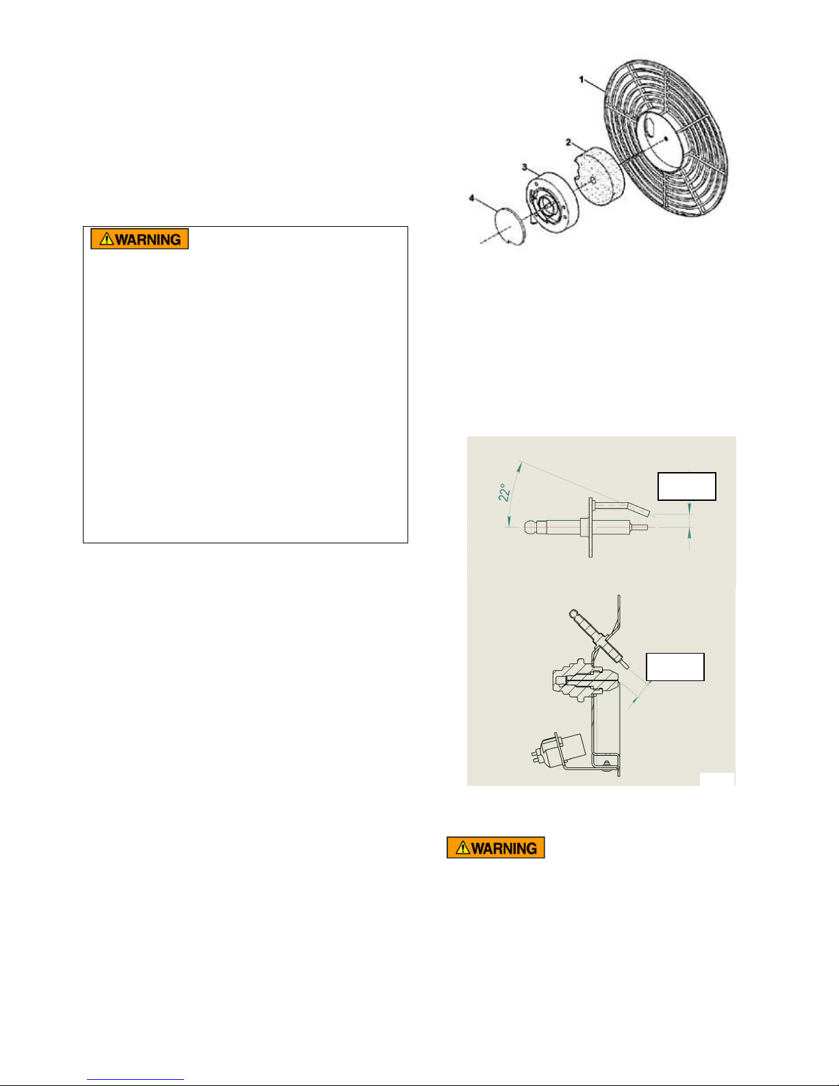
Air intake and output filters
Every 500 hours: Inspect air filters. Remove filter
end cover (1), wash air intake filter (2) using a
light detergent and dry it thoroughly before
reinstalling. Replace air outlet filter (4) (Fig. 8)
Fig. 8
Fuel filter
Inspect, clean or replace fuel filter every 500
hours or less as needed.
Ignition electrodes
Clean, adjust and if necessary replace ignition
electrode every heating season. For electrode
gaps see Fig. 9.
0.26”
(6.6 mm)
0.48”
(12.1 mm)
Fig. 9
Compressor Pressure Adjustment (Fig. 10)
The compressor pressure is
factory set and must be checked and
adjusted by service persons only. Tampering
with the unit may cause incorrect combustion
and dangerous emissions.
To check and adjust the pressure proceed as
follows:
Remove the pressure gauge port cap (1).
Connect a 0-15 psi pressure gauge to the
pressure gauge port. Be sure that the pressure
2
Page 10

gauge connection is 1/8 inch BSP (parallel
PORT
ADJUSTMENT
thread; not tapered). Start heater, read the air
pressure value and compare to the air pressure
(at right) required for your model. If adjustment
of air pressure is required, loosen the hex nut at
the Air Vent Hole and turn the pressure
adjustment screw (2) with a 5/32 inch or 4mm
hex key or allen wrench. Turn the pressure
adjustment screw clockwise to increase or
counterclockwise to decrease the pressure.
Tighten the hex nut and remove the hex key from
the adjustment screw. Check the pressure
shown on the pressure gauge again and repeat
the procedure as required to obtain the correct
air pressure
.
PRESSURE
SCREW
AIR VENT
HOLE
PRESSURE
GAUGE
1/8” BSP
Fig. 10
8. Wiring Diagram
Model
JAZ 42 4.8
JAZ 80 4.1
JAZ 80 W 4.1
JAZ 125 5.1
JAZ 160 5.5
Electrical
Inspect all internal wiring, electrical parts and
connections. Clean or replace parts as needed.
Air Pressure (psi)
10. Troubleshooting
3
Page 11

Fuse is blown.
Replace fuse.
Fuel filter clogged.
Clean or replace fuel filter.
operation.
PROBLEM POSSIBLE CAUSE SOLUTION
Motor will not start
GREEN INDICATOR LIGHT IS
QUICKLY FLASHING
(4 flashes/second)
Faulty motor/capacitor. Check and replace if required.
Motor runs, but the fuel does
not ignite and the heater
shuts off after 5 seconds.
GREEN INDICATOR LIGHT IS
QUICKLY FLASHING
(4 flashes/second)
Fuel nozzle clogged.
Heater stops during
operation:
GREEN INDICATOR LIGHT
SLOWLY FLASHING (1
flash/4 seconds)
No power or low voltage Check power supply and voltage.
Reset: Turn On/Off switch to O and then to I
[needed here?]
Thermostat is set too low. Turn thermostat knob clockwise to higher
setting.
Faulty or damaged power cord or
Check and replace if needed.
extension cord.
Low or empty fuel tank. Fill tank with fresh kerosene [fuel?].
Dirty or wrong fuel. Remove fuel and replace with clean kerosene
[fuel?].
Leaks in fuel or air hoses. Check hoses and replace with original parts if
necessary.
Faulty ignition transformer or
Replace ignition transformer or control board.
control board.
Spark plug dirty or fouled.
Check and clean or replace spark electrode.
Clean nozzle by blowing compressed air
through front of nozzle; replace if necessary.
The desired room temperature
has been reached. Heater is in
No fault. Normal operation. To start, turn
thermostat knob clockwise to a higher setting.
STAND-BY MODE.
GREEN INDICATOR LIGHT
NOT LIT
Reset: Turn On/Off switch to O and then to I
Fuse blown Replace Fuse
GREEN INDICATOR LIGHT IS
QUICKLY FLASHING
(4 flashes/second)
Loss of power supply during
Flame Incorrect: Fuel/ Air
mixture too rich (too much fuel or
not enough air).
Flame Incorrect: Fuel/Air mixture
too lean (too much air or not
enough fuel).
2
Check power supply.
Provide correct fuel/air mixture. Check for
blockage of air inlet, dirty or damaged fan, or
bad fuel. Remove obstructions to good air
flow, clean parts. Be sure correct fuel or
clean kerosene is used. Be sure compressor
pressure is correct.
Provide correct fuel/air mixture: Check for low
fuel level. Check for dirty fuel, dirty fuel or air
filters, or dirty nozzle and replace as required.
Be sure correct fuel or clean kerosene is
used. Be sure compressor pressure is
correct.
Page 12

Motor Overheating
Allow motor to cool and restart. Identify and
correct cause of overheating. If needed, call
Customer Service.
Faulty or Dirty Photocell (Flame
Faulty Control Board Replace control board
For Spot Climate Control Customer Service (9 am to 5 pm EST):
Call (239) 936-1555 and select SCC Customer Service.
Sensor)
Clean or replace photocell
3
Page 13

Australia Munters Pty Limited, Phone +61 2 6025 6422, Fax +61 2 6025 8266, Austria via sales organization in Germany, Brazil Munters Brasil Industria e Comercio Ltda, Phone +55 11 5054
0150, Fax +55 11 5054 0883, China Munters Air Treatment Equipment (Beijing) Co., Ltd., Phone +86 10 80 481 121, Fax +86 10 80 483 493, Denmark via sales organization in Sweden,
Finland Munters Oy, Phone +358 9 83 86 030, Fax +358 9 83 86 0336, France Munters France S.A., Phone +33 1 34 11 57 50, Fax +33 1 34 11 57 51, Germany Munters Euroform GmbH,
Phone +49 241 89 00 0, Fax +49 241 89 00 5199, Indonesia Munters, Phone +62 21 9105446-7, Fax +62 21 5310509, Italy Munters Italy S.p.A., Phone +39 0183-52 11, Fax +39 0183-521
333, Japan Munters K.K., Phone +81 3 5970 0021, Fax +81 3 5970 3197, Kingdom of Saudi Arabia and Middle East Hawa Munters, c/o Hawa United Cooling Syst. Co. Ltd., Phone +966 1
477 15 14, Fax +966 1 476 09 36, Korea Munters Korea Co,. Ltd, Phone +82 2 761 8701, Fax +82 2 761 8777, Mexico Munters Mexico Phone +52 722 270 40 30, Fax +52 722 270 41 95,
Norway via sales organization in Sweden, South Africa and Sub-Sahara Countries Munters (Pty) Ltd, Phone +27 11 997 2000, Fax +27 11 608 3501, Spain Munters Spain S.A., Phone +34
91-640 09 02, Fax +34 91-640 11 32, Sweden Munters Europe AB, Phone +46 8 626 63 00, Fax +46 8 754 56 66, Switzerland via sales organization in Germany, Thailand Munters (Thailand)
Co. Ltd., Phone +66 2 645 2708-12, Fax +66 2 645 2710, United Kingdom Munters Ltd, Phone +44 845 644 3980, Fax +44 845 644 3981, USA Munters Corporation Fort Myers, Phone +1
239 936 1555, Fax +1 239 936 8858, Munters Corporation Mason, Phone +1 888 335 0100, Fax +1 517 676 7078, Export & Other countries Munters, Phone +46 8 626 63 00, Fax +46 8 754 56
Munters reserves the right to make alterations to specifications, quantities, etc., for production or other reasons, subsequent to publication.
66.
© Munters, 2012
4
 Loading...