

Page 1
IA Inlet
Instruction Manual
Actuator
IA Inlet Actuator
Models: IA0090 • IA0090P • IA0250D • IA0250DP
QM1235r2
1© Munters Corporation, April 2019
Page 2

IA Inlet Actuator
Manual for use and Maintenance
Thank You:
Thank you for purchasing a Munters IA Inlet Actuator. Munters equipment is designed to be the highest performing,
highest quality equipment you can buy. With the proper installation and maintenance it will provide many years
of service.
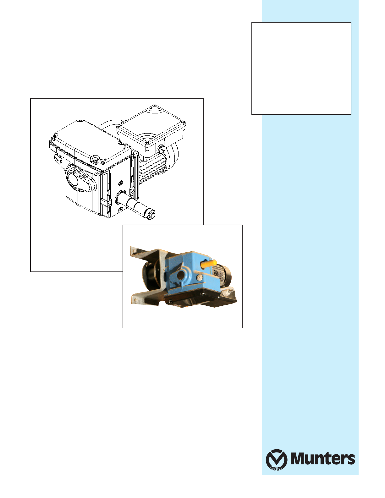
Description:
The IA0090/IA0250D motor gearbox is a maintenance-free, compact drive unit for accurately opening and
closing air inlet flaps, air valves and ventilation curtains in livestock houses and crop storage buildings.
The IA0090/IA0250D motor gearbox features a self-braking worm gear transmission. This transmission ensures
that the drive shaft is not rotatable when the drive unit is stopped. The combination of carefully matched pinion and
worm reductions results in a quiet mechanical transmission.
The IA0090/IA0250D motor gearboxes feature a power switching integrated linear limit switch system with duty
and safety switches with an excellent switching precision of the end positions. The maximum switching range of the
limit switch system equates to 55 revolutions of the drive shaft. With use of an optional potentiometer built-in set, it
is possible to precisely feedback intermediate and end positions to a (climate) computer.
The IA0090/IA0250D motor gearboxes are finished with a blue powder coating and are supplied including
mounting bolts and spring washers.
IA0090 motor gearboxes: IA0250D motor gearboxes:
• Drive torques of 1000 lb.-in.; • Drive torques of 3540 lb.-in.;
• 1.2 at 60 Hz mains frequency; • 1.2 at 60 Hz mains frequency;
Suitable for intermittent use, duty class 3-30%, duty cycle maximum 25 minutes;
Provided with a two-sided output drive shaft for mounting one winch or belt drum or two 16-tooth
1/2”x5/16” zinc-plated sprockets for chain couplings;
• Manual drive enabled by means of a hexagon socket in electric motor shaft;
• Electric motors are standard tropic-proof and conform to protection class IP55;
• Available as 1-phase 115 V (60 Hz) electric motor with UL and CSA approval.
Please Note:
To achieve maximum performance and insure long life from your Munters product it is essential that it be installed
and maintained properly. Please read all instructions carefully before beginning installation.
Warranty:
For Warranty claims information see the “Warranty Claims and Return Policy” form QM1021 available from the
Munters Corporation office at 1-800-227-2376 or by e-mail at aghort.info@munters.com.
Conditions and Limitations:
• Products and Systems involved in a warranty claim under the “Warranty Claims and Return Policy” shall have
been properly installed, maintained and operated under competent supervision, according to the instructions
provided by Munters Corporation.
• Malfunction or failure resulting from misuse, abuse, negligence, alteration, accident or lack of proper installation
or maintenance shall not be considered a defect under the Warranty.
2
QM1235r2
© Munters Corporation, April 2019
Page 3

Index
Chapters Page
1. Unpacking the Equipment
1.1 Technical specifications IA0090 motor gearbox 4
1.2 Configurations IA0090 motor gearbox 4
1.3 Options for IA0090 motor gearbox 5
1.4 Dimensions IA0090 motor gearbox 5
2. Installation Instructions
2.1 Mounting the IA0090 motor gearbox. 6
2.2 Mounting the drum, winch belt and couplings (configuration 1) 7
2.3 Pre-winding the winch belt onto the belt drum (configuration 1) 8
3. Connection and Operations
3.1 Connection and operation - abbreviations 9
3.2 Connecting the control components: switch materials and cable lengths 9
3.3 Overview: connections and elements for “Operating & Setting” 9
3.4 Rotational directions and end positions IA0090 motor gearbox 11
3.5 Wiring diagrams IA0090 motor gearbox 11
3.6 Setting the limit switch system 14
3.7 Potentiometer installation set: installation 17
3.8 Potentiometer table IA0090 motor gearbox (i=1,0) 18
4. Maintenance
4.1 Maintenance IA0090 motor gearbox 19
QM1235r2
3© Munters Corporation, April 2019
Page 4
About the Equipment
1.1 Technical Specifications IA0090/IA0250D Motor Gearbox
Mechanical IA0090 IA0250D
Torque 1000 lb.-in. 3540 lb.-in.
Speed 1.2 rpm 1.2 rpm
Winch belt speed 6.2 - 6.9 inch/min 6.2 - 6.9 inch/min
Winch belt length 39.4 inch 39.4 inch
Drive unit Self-locking Self-locking
Weight 34.2 lb 66 lb
Electrical
Supply voltage (A - 532601) 115 V 115 V
Maximum current (A - 532601) 2.5 A 4 A
Power 90 W 180 W
Environment
Protection class IP55 IP55
Operating temperature 0 tot 40 °C (32 tot 104 °F) 0 tot 40 °C (32 tot 104 °F)
1.
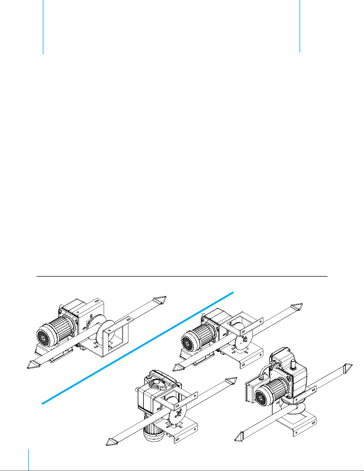
1.2 Configurations IA0090/IA0250D Motor Gearbox
The IA0090/IA0250D ships in 2 boxes, Box 1 of 2 is the Gear Motor and Box 2 of 2 is the installation kit.
• The IA0090/IA0250D is standard delivered with a 1-phase motor: A - 115V
• The IA0090/IA0250D is standard delivered with limit switch system and mounting kit.
• Configurations include double belt drum, Belt Drum w/option to use cables.
• Options: Potentiometer
Options and accessories are ordered separately.
CONFIGURATIONS: Belt drum
Ceiling Mount
4
QM1235r2
Wall Mount
© Munters Corporation, April 2019
Page 5
7.55"
Items to Order Separately:
About the EquipmentChapter 1
IA0090, IA0090P
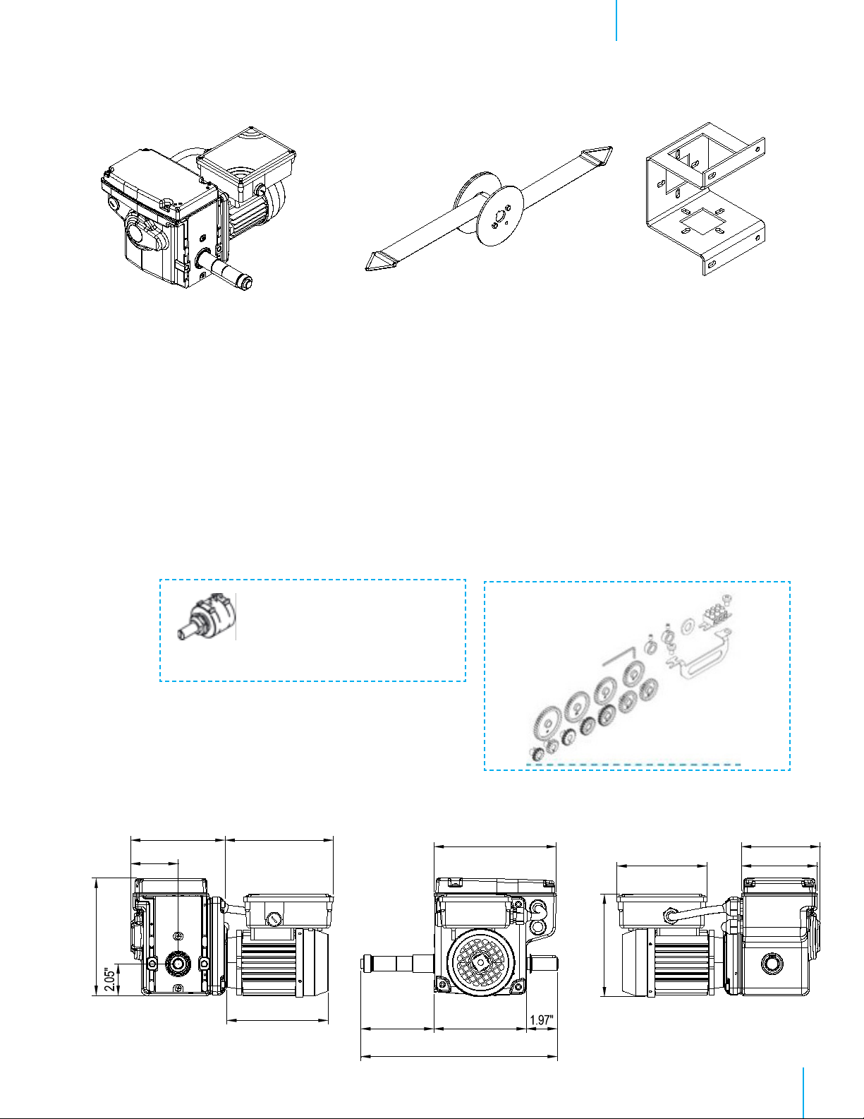
1.3 Options for IA0090 Motor Gearbox
Potentiometer: Position feedback IA0090P
An optional potentiometer built-in set (AC1429) for the IA0090 motor gearbox. Position feedback
which works in combination with the limit switch system.
The built-in set with potentiometer makes it possible to signal with precision to a (climate) computer, not
just the start and end positions of the limit switch system, but also all the intermediate positions of the
driven system.
AC1429
Specifications
Resistance: 5kΩ (R5K)
Revolutions: 10 (S10)
Drum Kit with Mounting Bracket AC2905
AC1429
1.4 Dimensions IA0090 Motor Gearbox
6.2"
3.1"
6.9"
6.55"
4.72"
5.94"
12.64"
7.87"
6.61"
5.79"
5.05"
4.88"
QM1235r2
5© Munters Corporation, April 2019
Page 6
Installation Instructions
IA0090, ACTUATOR
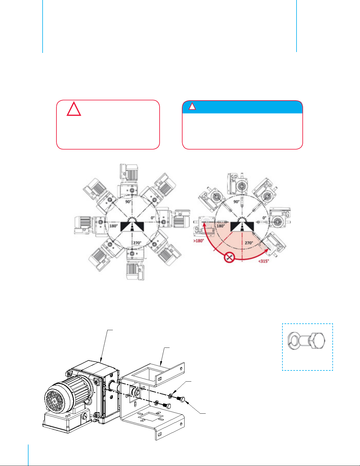
2.1 Mounting the IA0090/IA0250D Motor Gearbox.
Mount the IA0090/IA0250D motor gearbox according to the following instructions:
Always use an allowed mounting position as shown in image 3.1.
!
!
CAUTION
Please ensure that the IA0090 is
mounted securely, so that the building
structure can sufficiently absorb the
forces applied.
*Please observe the following allowed mounting positions when installing the IA0090 Motor Gearbox
When mounting the IA0090, ensure that the
Attention:
motor cover remains accessible so you will
have no problems connecting, setting and
operating the IA0090
2.
Image 2.1
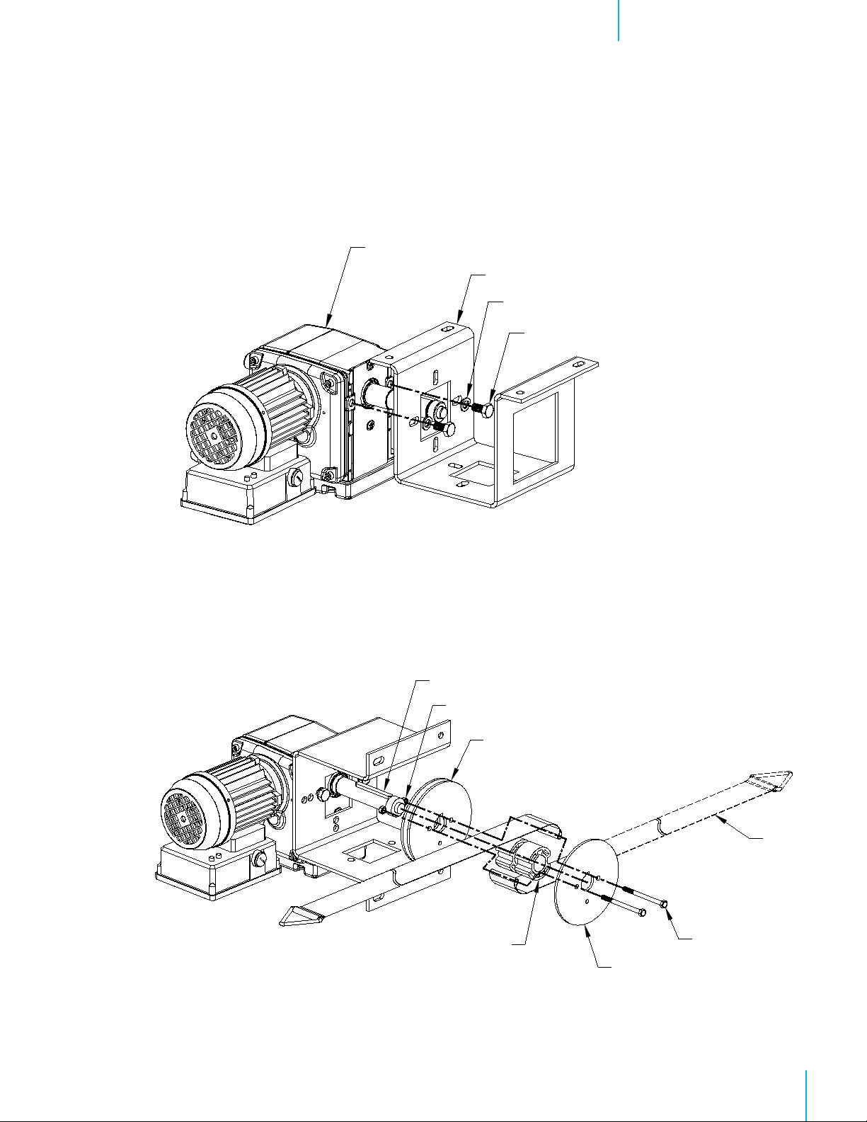
Use the M10 bolt and washer from the mounting kit to mount the plates to the gearbox.
Mounting IA0090/IA0250D: Belt Drum - Wall Mount
Mount the mounting plate for wall assembly to the IA0090 as follows:
MOUNTING BRACKET
M10 SPLITLOCK WASHER
M10x20 BOLT
M10 bolt
6
QM1235r2
© Munters Corporation, April 2019
Page 7
KEY
SINGLE DRUM DISC
Installation InstructionsChapter 2
IA0090, ACTUATOR
Mounting IA0090/IA0250D: Belt Drum - Ceiling Mount (Configuration 1)
Mount the square mounting plate to the IA0090 by choosing option 1 (side) or 2 (foot).
MOUNTING BRACKET
M10 SPLITLOCK WASHER
M10x20 BOLT
Configuration 1
2.2 Mounting the Drum, Winch Belt and Couplings
Mount the drum, winch belt (single or double) and couplings for the IA0090 as follows:
NUT
DOUBLE
DRUM DISC
(2) DRUM SPACERS
BELT
M6x80 BOLT
QM1235r2
7© Munters Corporation, April 2019
Page 8

Installation InstructionsChapter 2
2.3 Pre-winding the Winch Belt onto the Belt Drum
To safely use the belt drum and winch belt of the IA0090/IA0250D it is necessary to pre-wind the
belt at least ½ a revolution onto the drum.
Belt drum with single or double belt:
• At least ½ revolution
!
CAUTION
Not pre-winding the winch belt may result
in injury at high belt or drum loads.
8
QM1235r2
© Munters Corporation, April 2019
Page 9

Connection and Operations
3.1 Connection and Operation: Abbreviations
Symbol Description
A Endposition A
B Endposition B
CW (A) Clockwise rotational direction (A)
CCW (B) Counterclockwise rotational direction (B)
ESU Limit switch system
K1 Connection block
K2 Connection block Potentiometer
L1, L2 Power source
M Electric motor
N Neutral conductor
P Potentiometer
PS Potentiometer installation set
P71, P72* Contacts for automatic control (open or closed).
* Suitable for inductive load of 115/220 V - 2,5 A
PE Ground (Earth Contact)
Q41 Motor Safety Switch
S1 Toggle switch (3 positions)
S11 Duty switch limit switch system A
S12 Duty switch limit switch system B
S21 Safety switch limit switch system A
S22 Safety switch limit switch system B
S111 Manual switch Stop - Open - Close - Automatic
U1 Motor connection (U1)
V1 Motor connection (V1)
W1 Motor connection (W1)
Z1 Gear Wheel Threaded Shaft (Potentiometer Set)
Z2 Gear Wheel Potentiometer Shaft (Potentiometer Set)
PTO Protection Thermal Overload (Switch)
R Relay
3.
3.2 Connecting the control components: Switch Materials and cable lengths
ATTENTION:
Please use only suitable control components and switch materials. Make sure you are using the correct equipment by
consulting the information on the control components and switch materials.
3.3 OVERVIEW: Connections and Elements for “Operating & Setting”
The overview in image 3.3.2 shows the most important connections, parts and elements for operating and setting a
IA0090 motor gearbox. As shown in image 3.3.1, remove the limit switch cover of the gearbox.
TIP: Cover in image 3.3.2 is also removed for a complete overview. However it is not necessary to remove cover in
this manual.
QM1235r2
9© Munters Corporation, April 2019
Page 10

Connection and OperationsChapter 3
Unscrew the four bolts and remove the limit switch cover while the gasket stays in place.
1. Limit switch cover
2. Gasket
3. Bolts
4. Cover electric motor
Image 3.3.1
The overview of a IA0090 motor gearbox. The detailed diagrams for connecting are shown in Step 3.5
10
QM1235r2
Image 3.3.2
© Munters Corporation, April 2019
Page 11
Connection and OperationsChapter 3
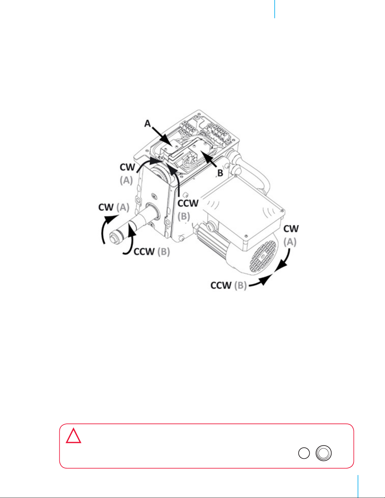
3.4 Rotational Directions and End Positions IA0090 Motor Gearbox
The rotational direction for the IA0090 is Clockwise [CW] (A) which is towards the motor and Counter
Clockwise [CCW] (B) which is away from the motor. Also visible are the corresponding limit switches for setting
the end positions A and B. See figure below.
Based on where the IA0090 and inlets are mounted and the direction the belt is wrapped on the drum,
determine which direction will be open and which will be close.
3.5 Wiring Diagrams IA0090 Motor Gearbox
Two wiring diagrams are applicable during installing and setting of the IA0090 gearbox. A temporary and a
permanent diagram are used in a number of steps according to Step 3.5.
Temporary connections (diagram 3.5.2):
This is only used for setting switch, according to Step 3.6, prior to making the permanent connections of the
IA0090 gearbox. Therefor a Temporary Power Cable is connected to the switch.
Permanent connections (diagram 3.5.4):
Make the permanent connections of the IA0090 gearbox after setting of the switch.
TIP: If the operation of position feedback is applicable, installation and setting of a potentiometer (P) is done separately in
Step 3.7 and Step 3.8.
!
CAUTION
The IA0090 motor gearbox is standard delivered with switch S1 in stop position. Switch S1
is still in STOP position when starting temporary or permanent connections!
Stop
S1
!
QM1235r2
11© Munters Corporation, April 2019
Page 12

Connection and OperationsChapter 3
● Connect the Temporary Power Cable.
The image and the diagram below show the connections of a Temporary Power Cable.
Image 3.5.1
● Go to Step 3.6 and set the Limit Switch System prior to the permanent connections.
● Remove the Temporary Power Cable.
12
QM1235r2
IA0090
Image 3.5.2
© Munters Corporation, April 2019
Page 13

Connection and OperationsChapter 3
CCW (Counter Clockwise)
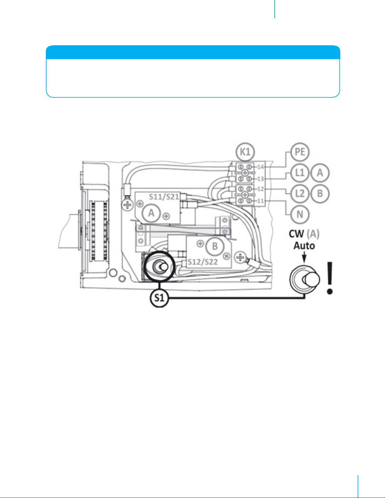
● Make the permanent connections.
The image and the diagram below show the permanent connections of the IA0090 gearbox.
GROUND
CW (Clockwise)
NEUTRAL
Image 3.5.3
* Suitable for inductive load of 115V - 2,5 A
ATTENTION:
When setting the Limit Switch after the permanent
connections, make sure that S111 and P71 (or
equivalent parts) are configured toprovide power
to L1 (13) of connection block K1!
TIP: Reverse the direction of
rotation of the IA0090 if desired.
The direction of rotation can be
turned by changing connections
12 and 13 (L2 and L1) in the
connection block K1.
Diagram 3.5.4
IA0090
QM1235r2
13© Munters Corporation, April 2019
Page 14

Connection and OperationsChapter 3
Set Screws in Adjusting Ring
3.6 Setting the Limit switch system
Delivery:
Make the connections from the controller to the actuator terminal block (K1) depending on which direction is Open and
which is Close. See Image 3.5.3.
Terminal Block (K1)
Threaded Shaft
End Position (B)
End Position (A)
Toggle Switch (S1)
Textured Brass Nut
Image 3.6.1
Setting the Limits: See Image 3.6.1
1. Put switch (S1) into Stop position.
2. Apply power to the Clockwise [CW] (A) terminal 13.
3. Find the Allen Wrench that ships with the actuator.
4. Loosen the (2) Set Screws on each Adjusting Ring, at each end of the threaded shaft.
Setting the Clockwise [CW] (A) limit:
1. Put switch (S1) into CW (auto) position.
2. When end position [CW] (A) is reached put switch (S1) back to Stop.
3. On the [CW] (A) end, turn the Textured Brass Nut hand tight against the stop.
4. Now turn the Adjusting Ring over the Textured Brass Nut so far, that the working switch is just connected by the long
Adjusting Screw.
5. Now tighten the Set Screws firmly on the Textured Brass Nut. The Adjusting Ring cannot turn on the Brass Nut anymore.
Image 3.6.2
Setting the Counter Clockwise [CCW] (B) limit:
1. Put switch (S1) into CCW position.
2. When end position [CCW] (B) is reached put switch (S1) back to Stop.
3. On the [CCW] (B) end, turn the Textured Brass Nut hand tight against the stop.
4. Now turn the Adjusting Ring over the Textured Brass Nut so far, that the working switch is just contacted by the long Adjusting
Screw.
5. Now tighten the Set Screws firmly on the Textured Brass Nut. The Adjusting Ring cannot turn on the Brass Nut anymore.
The Limits are now set.
14
QM1235r2
© Munters Corporation, April 2019
Page 15
Connection and OperationsChapter 3
ATTENTION:
If the motor gearbox is manual operated by means of the hexagon socket in the electric motor shaft, with an limit switch
system which is set, it has to be checked that the end positions of the system will not be exceeded.
This can cause damage to the limit switch system, as a result of which the limit switch system will not function well
anymore.
Operating mode
Make sure the switch S1 is put in CW (A)/Auto position when permanent connections are done and
setting of the Switch is finished.
Image 3.6.3
Place the limit switch cover①, with the gasket ① still in place, and mount it with the four bolts.
See image 3.3.1.
TIP: If the feedback option is applicable, then first install and set the potentiometer (P) according to Step 3.4 and Step 3.5.
QM1235r2
15© Munters Corporation, April 2019
Page 16
Connection and OperationsChapter 3
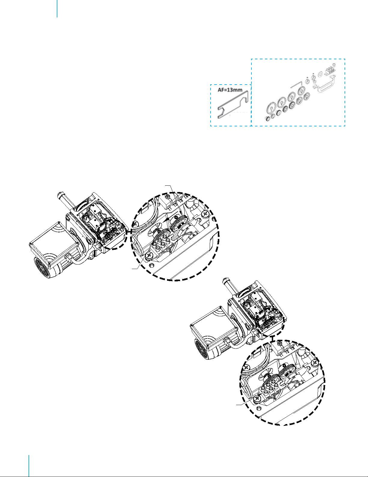
3.7 Potentiometer Installation Set: Installation
For an IA0090P, the Potentiometer set comes pre-installed in the
unit for a typical installation with a 1m belt we recommend using the
gears Z1 – 25 and Z2 – 25.
1. Slide Potentiometer with gear towards the other gear without
turning the shaft of the pot, so that the teeth on each gear nest
together and tighten the pot nut with the hex key wrench. See
Figure A.
2. The Potentiometer is pre-wired to the terminal bock K2. Make
the connections between the controller and terminal block K2. See Figure B. If the Pot is changing voltage from low
in the open position to high in the closed position then reverse the red and black wire on the controller side of terminal
block K2.
The Potentiometer installation is now complete.
For a 2m belt use gear ?? on the ??? shaft.
For a 3m belt use gear ?? on the ??? shaft.
Potentiometer
with Gear
Gear on IA
Shaft
Figure A
Terminal
Block K2
Figure B
WHITE
BLACK
RED
16
QM1235r2
© Munters Corporation, April 2019
Page 17
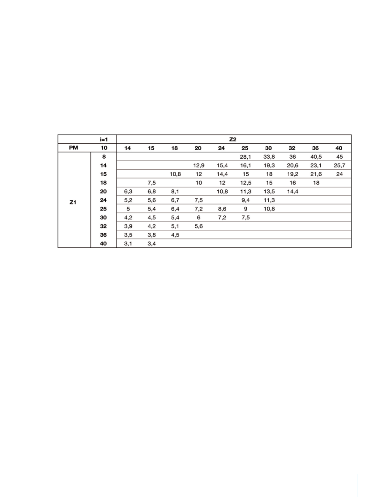
3.8 Potentiometer table IA0090 motor gearbox (i=1,0)
The table below can be used to select the necessary gearwheels when fitting a potentiometer and
installation set in an IA0090 motor gearbox. The table shows the maximum number of revolutions of
the drive shaft of the IA0090 motor gearbox.
A range of 9 revolutions of the potentiometer has been chosen for maximum precision and sufficient
reserve rotations when using a potentiometer. If the desired number of revolutions falls below the
minimum value given, a 5-turn potentiometer may be used. In that case, the values in the table that
give the maximum number of revolutions of the drive, should be divided by 2.
IA0090
Connection and OperationsChapter 3
QM1235r2
17© Munters Corporation, April 2019
Page 18

Maintenance
4.
4.1 Maintenance IA0090 Motor Gearbox
Regularly check your IA0090 motor gearbox for operation performance and possible grease leakage. Inform
your installer in case of grease leakage.
• Lubricant IA0090 – SPH grease – 1,9 lb
IA Actuator by Munters Corporation, Lansing, Michigan U.S.A. 1-800-227-2376
Munters Europe AB, Isafjordsgatan 1, P.O. Box 1150, SE-164 26 Kista, Sweden. Phone +46 08 626 63 00, Fax +46 8 754 56 66.
Munters Corporation 2691 Ena Drive Lansing, MI 48917 U.S.A. Phone +1 800-227-2376, Fax +1 517-676-7078
www.munters.us
Australia Munters Pty Limited, Phone +61 2 6025 6422, Brazil Munters Brasil Industria e Comercio Ltda, Phone +55 41 3317 5050, Canada/US Munters
Corporation Lansing, MI Phone +1 517 676 7070, China Munters Air Treatment Equipment (Beijing) Co. Ltd, Phone +86 10 80 481 121, Denmark Munters A/S,
Phone +45 9862 3311, India Munters India, Phone +91 20 3052 2520, Indonesia Munters, Phone +62 818 739 235, Italy Munters Italy S.p.A., Chiusavecchia,
Phone +39 0183 52 11, Japan Munters K.K., Phone +81 3 5970 0021, Korea Munters Korea Co. Ltd., Phone +82 2 761 8701, Mexico Munters Mexico, Phone
+52 818 262 54 00, Russia Munters AB, Phone +7 812 448 5740, Singapore Munters Pte Ltd., Phone +65 744 6828, South Africa and Sub-Sahara Countries
Munters (Pty) Ltd., Phone +27 11 997 2000, Spain Munters Spain S.A., Phone +34 91 640 09 02, Sweden Munters AB, Phone +46 8 626 63 00, Thailand
Munters Co. Ltd., Phone +66 2 642 2670, Turkey Munters Form Endüstri Sistemleri A.Ş, Phone +90 322 231 1338, USA Munters Corporation, Lansing MI Phone
+1 517 676 7070, Vietnam Munters Vietnam, Phone +84 8 3825 6838, Export & Other countries Munters Italy S.p.A., Chiusavecchia Phone +39 0183 52 11
18
QM1235r2
© Munters Corporation, April 2019
 Loading...