

Munters Green Field ECO Installation Manual
Installation Manual
Green
Field ECO
Green Field ECO Controller
Irrigation Controller
Ag/MIS/UmEN-2735-05/19 Rev 1.3
P/N: 116785

Green Field ECO Controller
Installation Manual
Rev 1.3, 02/2021
This manual for use and maintenance is an integral part of the apparatus together with the attached
technical documentation.
This document is destined for the user of the apparatus: it may not be reproduced in whole or in part,
committed to computer memory as a file or delivered to third parties without the prior authorization of the
assembler of the system.
Munters reserves the right to effect modifications to the apparatus in accordance with technical and legal
developments.
© Munters AB, 2018 2

Index
chapter page
1
INTRODUCTION
1.1 Disclaimer
1.2 Introduction
1.3 Notes
2
GENERAL INSTRUCTIONS
----------------------------------------------------------------------------------------
------------------------------------------------------------------------------------------------ -----------
------------------------------------------------------------------------------------------------ ---------
-----------------------------------------------------------------------------------------------------------------
----------------------------------------------------------------------------
2.1 Basic Requirements for On-Site Preparation
2.2 Frequency Inverters
2.3 General Dimensions
3
POWER SUPPLY WIRING
3.1 Main Power Wiring
3.2 Electrical Test
3.3 Firmware Upgrade
----------------------------------------------------------------------------------------------
---------------------------------------------------------------------------------------------
---------------------------------------------------------------------------
--------------------------------------------------------------------------------------------
-----------------------------------------------------------------------------------------------------
---------------------------------------------------------------------------------------------
3.3.1 ntroduction to/Guidelines for Firmware Upgrades
3.3.2 Accessing the Application
3.3.3 Running the Application
---------------------------------------------------------------
.........................................................
.....................................................................................................
........................................................................................................
10
10
12
13
13
14
14
7
7
7
7
8
8
8
9
4
ELECTRICAL INSTALLATION
4.1 Input/Output Layout
4.2 Output Terminals
------------------------------------------------------------------------------------------------
------------------------------------------------------------------------
-------------------------------------------------------------------------------------------
4.2.1 Output Terminal Wiring
4.2.2 Example of Output Wiring
4.3 Input Terminals
--------------------------------------------------------------------------------------------------
4.3.1 Input Terminal Wiring
4.3.2 Digital Input Examples
4.4 PC and Inter-Controller Communication
4.4.1 Card Installation
.....................................................................................................................
4.4.2 Wiring and Controller Setup
5
CONTROLLER SETUP
5.1 Start-Up
------------------------------------------------------------------------------------------------------------
5.2 Device Layout
5.3 Device List
---------------------------------------------------------------------------------
----------------------------------------------------------------------------------------------------
---------------------------------------------------------------------------------------------------------
.........................................................................................................
....................................................................................................
............................................................................................................
...........................................................................................................
------------------------------------------------------------------
................................................................................................
16
16
16
17
17
17
18
18
20
21
22
24
24
24
25
© Munters AB, 2018 3

5.4 Digital Input
5.5 Analog Input
------------------------------------------------------------------------------------------------------
-----------------------------------------------------------------------------------------------------
5.6 Hot Keys and Status Screens
6
CONTROLLER TEST PROCEDURE
6.1 Relays
6.2 Digital Input
6.3 Analog Input
6.4 Temperature
6.5 Humidity
7
SYSTEM CONFIGURATION PROCEDURE
--------------------------------------------------------------------------------------------------------------
------------------------------------------------------------------------------------------------------
-----------------------------------------------------------------------------------------------------
------------------------------------------------------------------------------------------------------
-----------------------------------------------------------------------------------------------------------
7.1 Device Delay Configuration
7.1.1 Example of Device Startup & Shutdown Order
7.1.2 Example of Stagger Valve Delay – Multiple Shifts
7.2 Pump Station Configuration
7.3 Valve Configuration
7.4 Valve Flow Rate
7.5 Water Meter
-----------------------------------------------------------------------------------------------------
--------------------------------------------------------------------------------------------
-------------------------------------------------------------------------------------------------
7.6 Dosing Channel Configuration
7.7 Dosing Configuration
7.8 Drainage Configuration
7.9 EC/pH Configuration
7.10 Cooling Configuration
7.11 Misting Configuration
7.12 History Resolution
------------------------------------------------------------------------------------------
---------------------------------------------------------------------------------------
------------------------------------------------------------------------------------------
-----------------------------------------------------------------------------------------
-----------------------------------------------------------------------------------------
-----------------------------------------------------------------------------------------------
7.13 System Nutrigation™ Check
7.13.1 Check if EC/pH is on Target
7.13.2 Water Run Time
7.13.3 Start/Stop Valve
--------------------------------------------------------------------------------
------------------------------------------------------------------
-------------------------------------------------------
---------------------------------------------------------------------------------
................................................................
..........................................................
----------------------------------------------------------------------------------
------------------------------------------------------------------------------
---------------------------------------------------------------------------------
..........................................................................................
.................................................................................................................
...............................................................................................................
26
26
28
31
31
32
32
33
33
34
34
35
36
37
38
39
39
41
42
43
43
44
44
44
45
45
45
46
8
CONTROLLER ADVANCED SETTINGS
8.1 Pump Station Configuration
8.2 Multiple Water Meters
8.3 Various Dosing Configurations
8.3.1 Method 1
8.3.2 Method 2
8.3.3 Method 3
.................................................................................................................................
.................................................................................................................................
.................................................................................................................................
8.4 Dosing Configuration
8.4.1 EC/pH Control Step 1
8.4.2 EC/pH Control Step 2
----------------------------------------------------------------------------------
----------------------------------------------------------------------------------------
------------------------------------------------------------------------------
------------------------------------------------------------------------------------------
...........................................................................................................
...........................................................................................................
------------------------------------------------------------
47
47
48
48
48
48
49
49
49
50
© Munters AB, 2018 4

9
PROGRAM MENU
9.1 Irrigation
9.1.1 Setting Irrigation that is Longer than 24 Hours
9.2 Influence Program
9.2.1 Using the Influences
9.2.2 Setting the Influences
9.3 Water Run Time
9.4 Dosing
9.4.1 Dosing Program
9.4.2 Dosing Injection Methods
9.5 Ext. Condition
9.6 Agitator
9.7 Selector
9.8 Filter Flushing
9.9 Cooling
9.10 Misting
9.11 Water Heating
------------------------------------------------------------------------------------
-----------------------------------------------------------------------------------------------------------
.................................................................
----------------------------------------------------------------------------------------------
...............................................................................................................
.............................................................................................................
9.2.2.1
9.2.2.2
9.2.2.3
9.2.2.4
9.2.2.5
-------------------------------------------------------------------------------------------------------------
------------------------------------------------------------------------------------------------------------
------------------------------------------------------------------------------------------------------------
------------------------------------------------------------------------------------------------------------
-------------------------------------------------------------------------------------------------------------
Radiation Influence on EC
Drainage Influence on Target Radiation Sum
Drain Influence on Minimum Time
VPD Influence on Target EC
Temperature Influence on Target EC
-------------------------------------------------------------------------------------------------
......................................................................................................................
.....................................................................................................
----------------------------------------------------------------------------------------------------
-----------------------------------------------------------------------------------------------------
--------------------------------------------------------------------------------------------------
..................................................................
.........................................
........................................................
................................................................
.....................................................
51
52
56
56
56
56
57
58
59
59
60
61
62
62
63
64
65
66
66
67
70
71
10 MANUAL OPERATION MENU
10.1 Irrigation Pause
10.2 Start/Stop Program
10.3 Start/Stop Valve
10.4 Filter Flushing
11 SETUP MENU
------------------------------------------------------------------------------------------
11.1 Time and Date
11.2 System Setup
11.3 Temperature Calibration
11.4 Humidity Calibration
11.5 EC/pH Calibration
--------------------------------------------------------------------------------------------------
--------------------------------------------------------------------------------------------
------------------------------------------------------------------------------------------------
-----------------------------------------------------------------------------------------------------
---------------------------------------------------------------------------------------------------
-----------------------------------------------------------------------------------------------------
--------------------------------------------------------------------------------------
-------------------------------------------------------------------------------------------
---------------------------------------------------------------------------------------------
11.5.1 Calibration of the EC/pH Monitor Transmitter
11.5.1.1 EC Calibration
11.5.1.2 pH Calibration
11.5.2 EC/pH Transmitter Monitor & Green Field ECO Correlation
11.6 Sensors Logging
11.7 Write to Data Plug
-------------------------------------------------------------------------------------------------
----------------------------------------------------------------------------------------------
---------------------------------------------------------------------
............................................................
.................................................................................
.................................................................................
..................................
72
72
73
73
74
75
75
76
78
78
78
79
79
80
82
82
83
© Munters AB, 2018 5

11.8 Read from Gold Data Plug
12 APPENDIX A: GREEN FIELD ECO PARTS LIST
13 APPENDIX B: TROUBLESHOOTING
13.1 Controller Display is Off
13.2 Output Malfunction
--------------------------------------------------------------------------------------------
-----------------------------------------------------------------------------------
----------------------------------------------------
---------------------------------------------------------------
--------------------------------------------------------------------------------------
14 APPENDIX C: REPLACEMENTS AND ADDITIONAL INSTALLATIONS
14.1 Power Supply Card
14.2 Relay Card
-------------------------------------------------------------------------------------------------------
15 APPENDIX D: SENSOR INSTALLATION AND DEFINITION
15.1 EC – pH Sensor Connection
15.1.1 EC Sensor Calibration
15.1.2 pH Sensor Calibration
15.2 Temperature/Humidity Sensor Connection
15.2.1 Humidity Sensor Definition
15.3 Sensor and Cable Specifications
--------------------------------------------------------------------------------------------
-----------------------------------
--------------------------------------------------------------------------------
......................................................................................................
.....................................................................................................
--------------------------------------------------------------
..............................................................................................
---------------------------------------------------------------------------
-----------------------
83
84
86
86
88
89
89
90
91
91
91
93
94
95
95
16 APPENDIX E: TECHNICAL SPECIFICATIONS
16.1 Technical Specifications
16.2 Controller Components
16.2.1 Keyboard & Display
16.2.2 Hardware Components
16.2.2.1 Components
16.2.2.2 Hardware Layout
16.2.3 Power Supply Card
16.2.3.1 Option A: 115 or 230 VAC Power Supply Card
16.2.3.2 Option B: 115VAC or 230VAC Power Supply Card with External 24VAC
Power for Output Devices
16.2.3.3 Option C: 12VDC Power Supply Card
16.2.4 Input and Output Card
17 APPENDIX F: MAIN MENU TREE
18 WARRANTY
------------------------------------------------------------------------------------------
---------------------------------------------------------------------------------------
---------------------------------------------------------------------------------------
.........................................................................................................
...................................................................................................
....................................................................................
..............................................................................
..........................................................................................................
...................................................................................
.................................................................................................
----------------------------------------------------------------
----------------------------------------------------
....................................
...............................................
96
96
96
97
97
97
98
99
99
100
101
102
103
104
© Munters AB, 2018 6

1 Introduction
1.1 Disclaimer
Munters reserves the right to make alterations to specifications, quantities, dimensions etc. for production
or other reasons, subsequent to publication. The information contained herein has been prepared by
qualified experts within Munters. While we believe the information is accurate and complete, we make no
warranty or representation for any particular purposes. The information is offered in good faith and with
the understanding that any use of the units or accessories in breach of the directions and warnings in this
document is at the sole discretion and risk of the user.
1.2 Introduction
Congratulations on your excellent choice of purchasing an Green Field ECO!
In order to realize the full benefit from this product it is important that it is installed, commissioned and
operated correctly. Before installation or using the fan, this manual should be studied carefully. It is also
recommended that it is kept safely for future reference. The manual is intended as a reference for
installation, commissioning and day-to-day operation of the Munters Controllers.
1.3 Notes
Date of release: July 2019
Munters cannot guarantee to inform users about the changes or to distribute new manuals to them.
All rights reserved. No part of this manual may be reproduced in any manner whatsoever without the
expressed written permission of Munters. The contents of this manual are subject to change without notice.
.
© Munters AB, 2018 7

2 General Instructions
•
Installation should be performed by authorized technicians only.
•
Verify that field components are working properly.
•
Apply all safety regulations.
•
Do not apply force or pressure on components during the installation procedure.
•
Refer to your supervisor if problems occur during installation procedure.
CAUTION
This unit must be installed inside, in a location protected from solar radiation and direct
rain.
•
2.1 Basic Requirements for On-Site Preparation
•
Verify power source between 115 VAC or 220 VAC ± 10%
•
On the unit is a silver label stating the unit’s voltage (110 or 230 VAC). Verify that your unit
supports the voltage supplied in your country.
•
Verify grounding connection < 10Ω
•
Environment temperature between -10° C / 14° F to +60° C / 140° F
•
Verify protection from damaging climate conditions
2.2 Frequency Inverters
•
Frequency inverters can cause severe electrical and electromagnetic interference. Therefore,
when employing a frequency inverter, it is critical that you carefully follow the manufacturer's
installation instructions.
•
In particular verify:
o
that the cable shielding between the inverter and any motor meets industry standards
o
proper grounding of the inverter's chassis and motor power cable
o
proper grounding of low voltage cable shield wire
o
that the controller and inverter cables are kept in separate conduits or wire bundles
© Munters AB, 2018 8
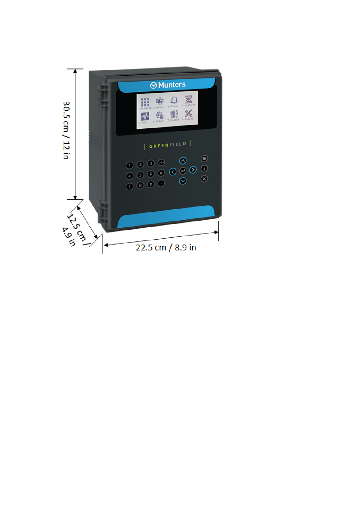
2.3 General Dimensions
•
© Munters AB, 2018 9
3 Power Supply Wiring
•
Main Power Wiring
•
Electrical Test
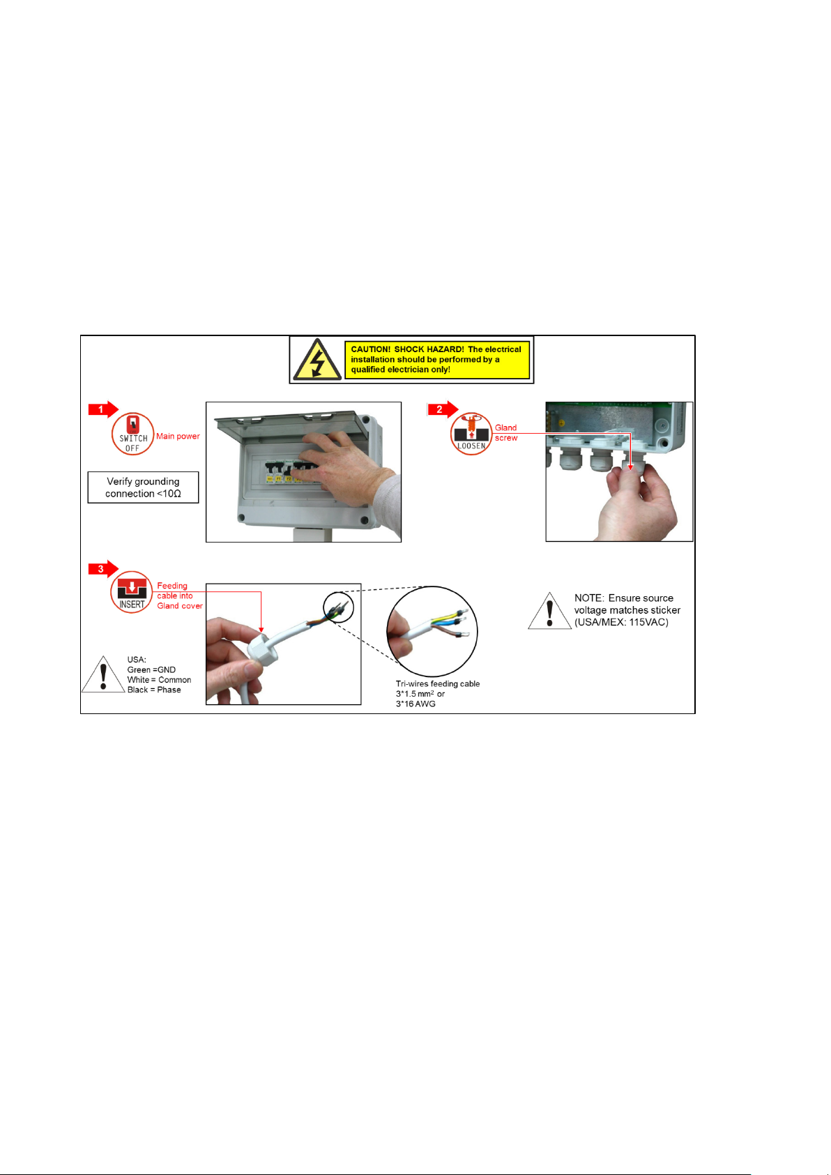
3.1 Main Power Wiring
© Munters AB, 2018 10

© Munters AB, 2018 11
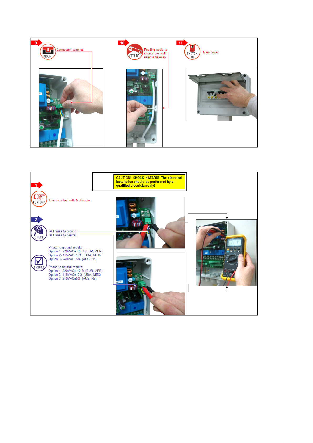
3.2 Electrical Test
© Munters AB, 2018 12
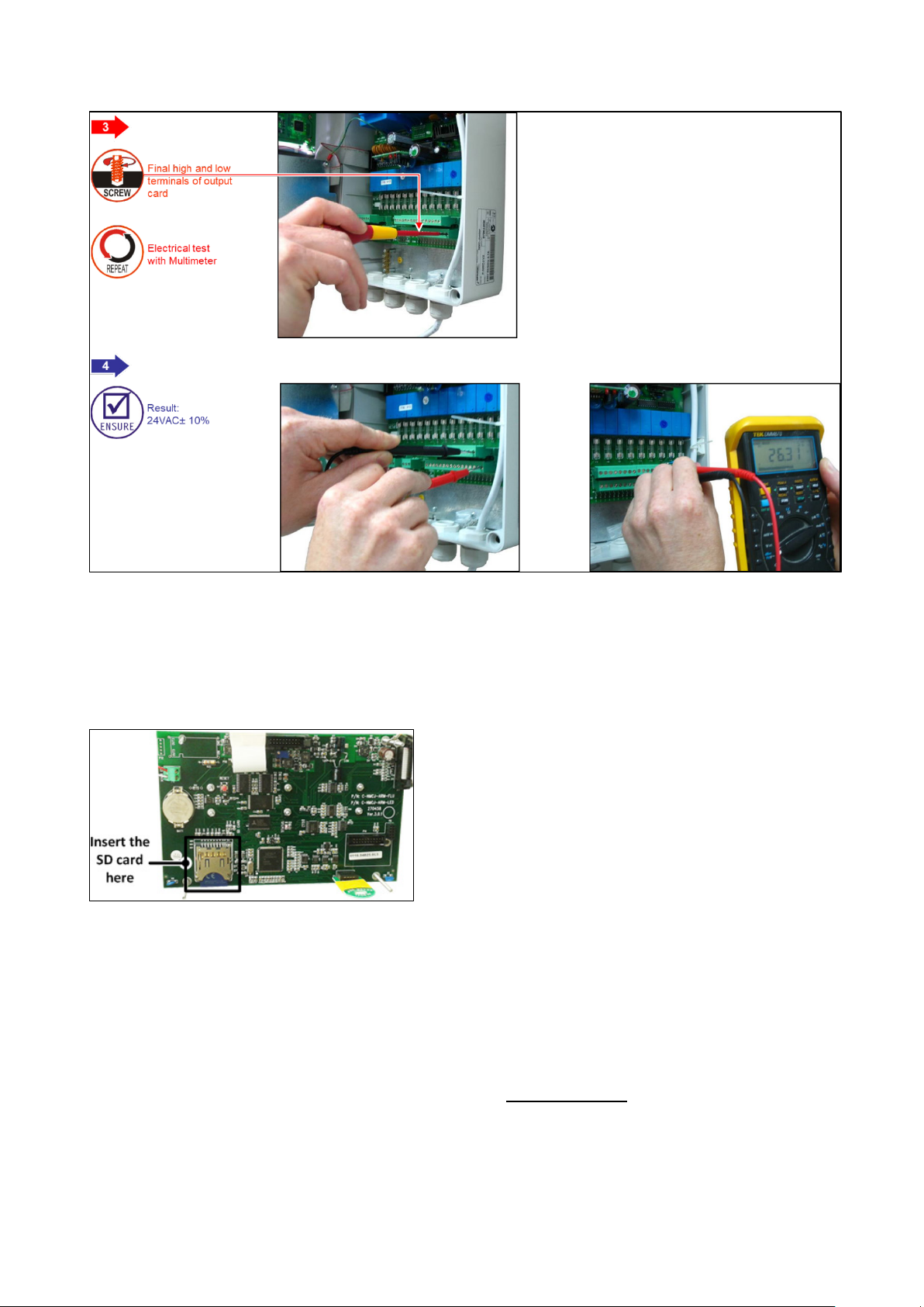
3.3 Firmware Upgrade
The Bootloader application enables installing or updating the system firmware. The application is menu
based and simple to use and enables updating the firmware from an SD card.
NOTE Verify that the card is in place before starting.
NOTE Green Field ECO supports up to 4 GB SD cards.
3.3.1
NTRODUCTION TO/GUIDELINES FOR FIRMWARE UPGRADES
•
While upgrading the firmware, a qualified Munters technician:
o
must be on site
o
must verify that the process is complete; verification includes checking all accessories
connected to the controller.
•
By default, in all sessions the controller returns to automatic mode. The technician must verify
that there are no manual mode devices in the field.
•
After upgrading the firmware the technician must upload settings and data from a data plug to
the controller.
© Munters AB, 2018 13
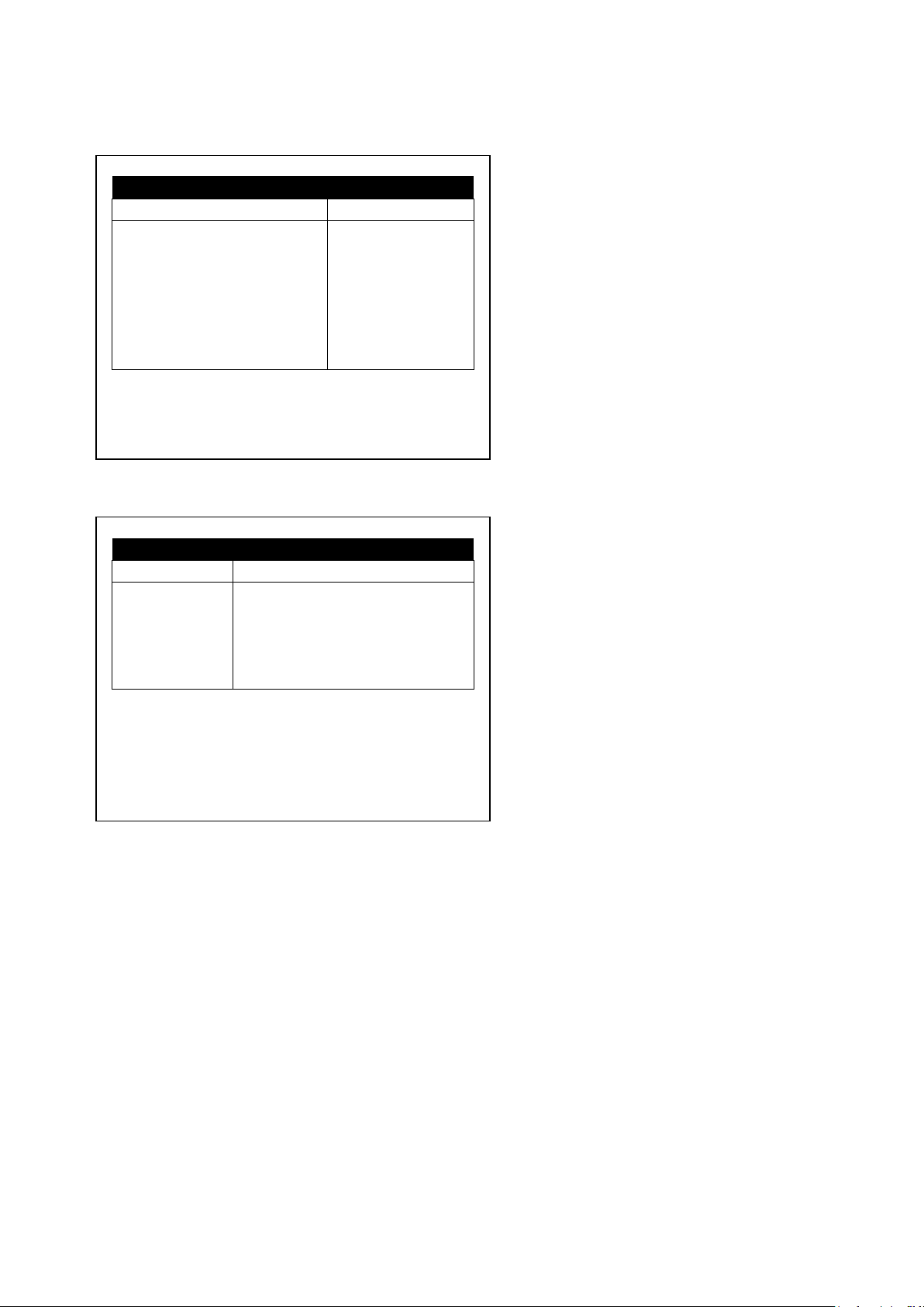
SELECT AN OPTION
Hardware Firmware
Hardware Test
Cancel Update
SELECT A FILE
Path: /
MUNTERS
<DIR>
12/Sept/2014
GREEN
FIELD~1
o
In the event that the controller sends a message regarding incomplete information, the
technician must enter the missing information manually and verify that the information is
correct in the field.
CAUTION Any upgrade that is not performed in accordiance with these guidelines could result in
unforseen malfunctions in the field equipment. Munters will not take responsibility for these
issues.
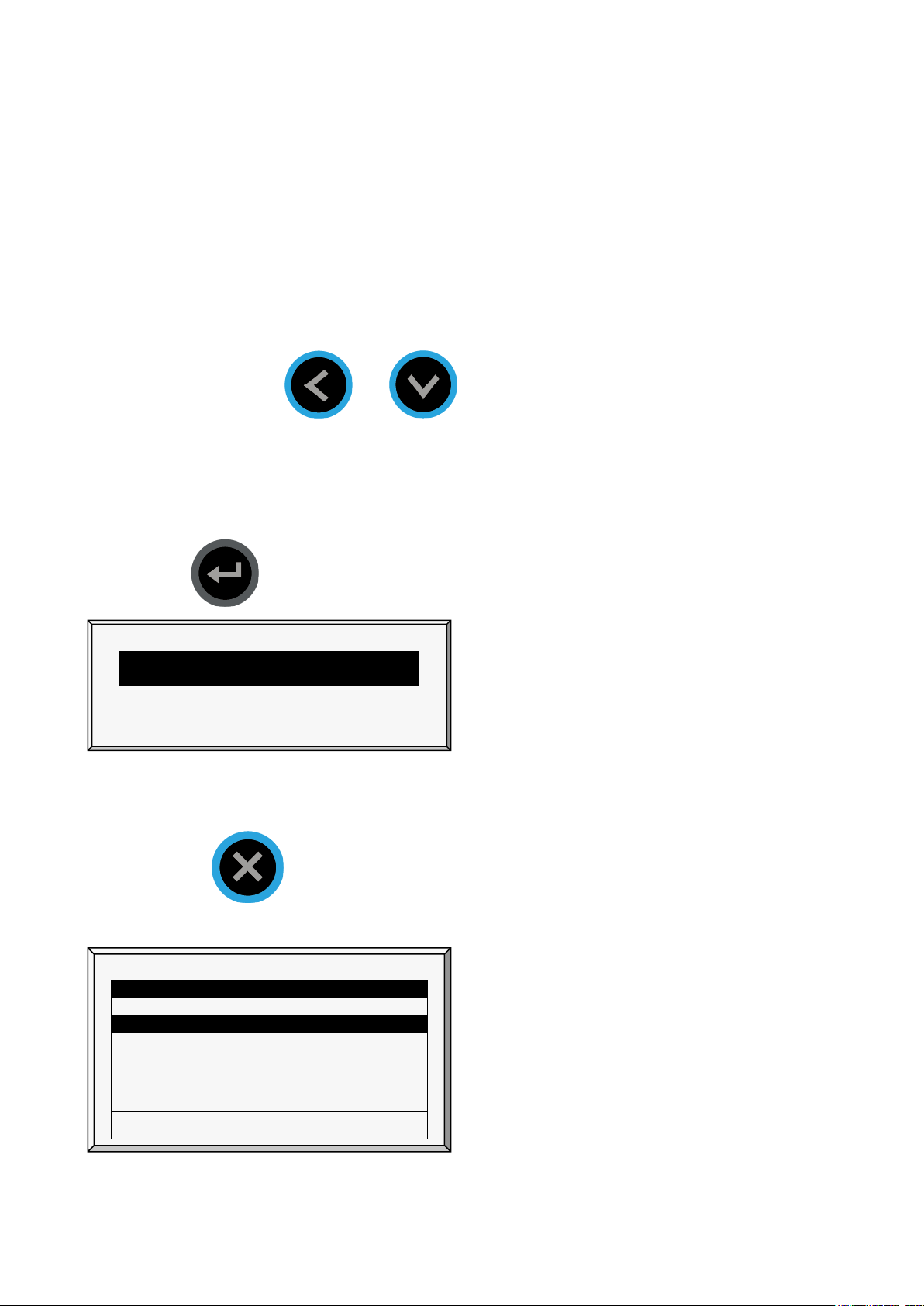
3.3.2 A
CCESSING THE APPLICATION
NOTE Before updating the firmware, save the settings to a data plug. Refer to Write to Data Plug,
page Error! Bookmark not defined..
1. Press and hold the and arrow keys.
2. Turn on the unit.
In the screen that appears, enter the password: 1948
NOTE If you enter the wrong password, an error message appears and the program goes to the Main
Screen. Repeat the process.
3. Press . The screen below appears.
NOTE Hardware Test is used for quality control only.
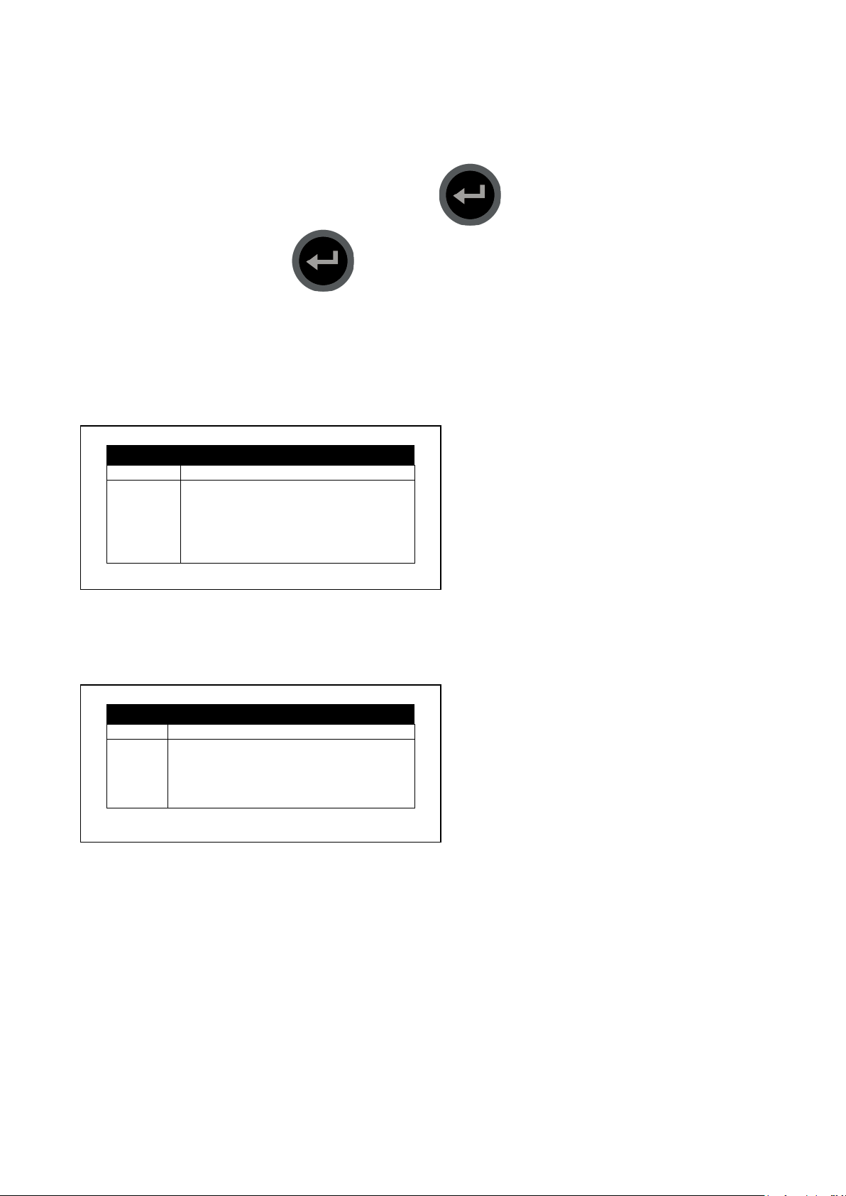
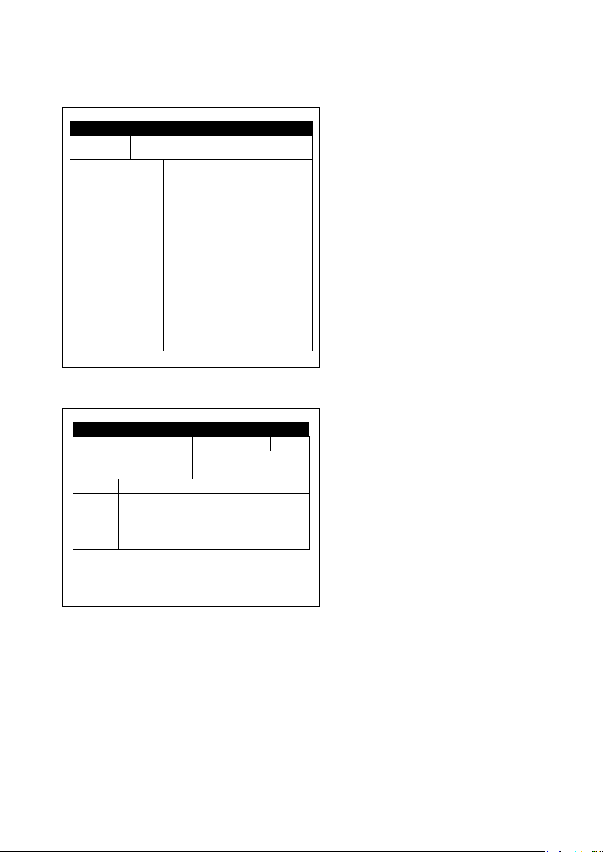
3.3.3 R
UNNING THE APPLICATION
NOTE Pressing you return to the previous menu.
1. Select Hardware Firmware. The following screen appears (example only):
GREEN FIELD <DIR> 13/Oct/2009
<DIR> 12/Sept/2014
Press ENTER to confirm selection or MENU to return.
2. Select the required directory.
© Munters AB, 2018 14

SELECT A FILE
Path: /
MUNTERSHEX1.04
<DIR>
12/Sept/2014
MUNTERSHEX1.06
<DIR>
12/Sept/2014
New Software Version
New Software Found
COLD START REQUIRED!!
Old Version:
8.02.00
New Version:
8.02.49
3. Press .
The following screen appears:
GREEN FIELD <DIR> 13/Oct/2009
4. Select the required software version.
5. Press .
6. A confirmation message appears. Select Yes.
7. Press .
NOTE Do not turn the unit off during the update! If there is an interruption (for example a power
outage), restart the process.
At the end of the process, the following screen appears (the version numbers are examples only):
Press ENTER To Continue.
8. Press and perform a Cold Start.
© Munters AB, 2018 15

4 Electrical Installation
•
Input/Output Layout, page 16
•
Output Terminals, page 16
•
Input Terminals, page 17
•
PC and Inter-Controller Communication, page 20
4.1 Input/Output Layout
4.2 Output Terminals
•
Output Terminal Wiring
•
Example of Output Wiring
© Munters AB, 2018 16
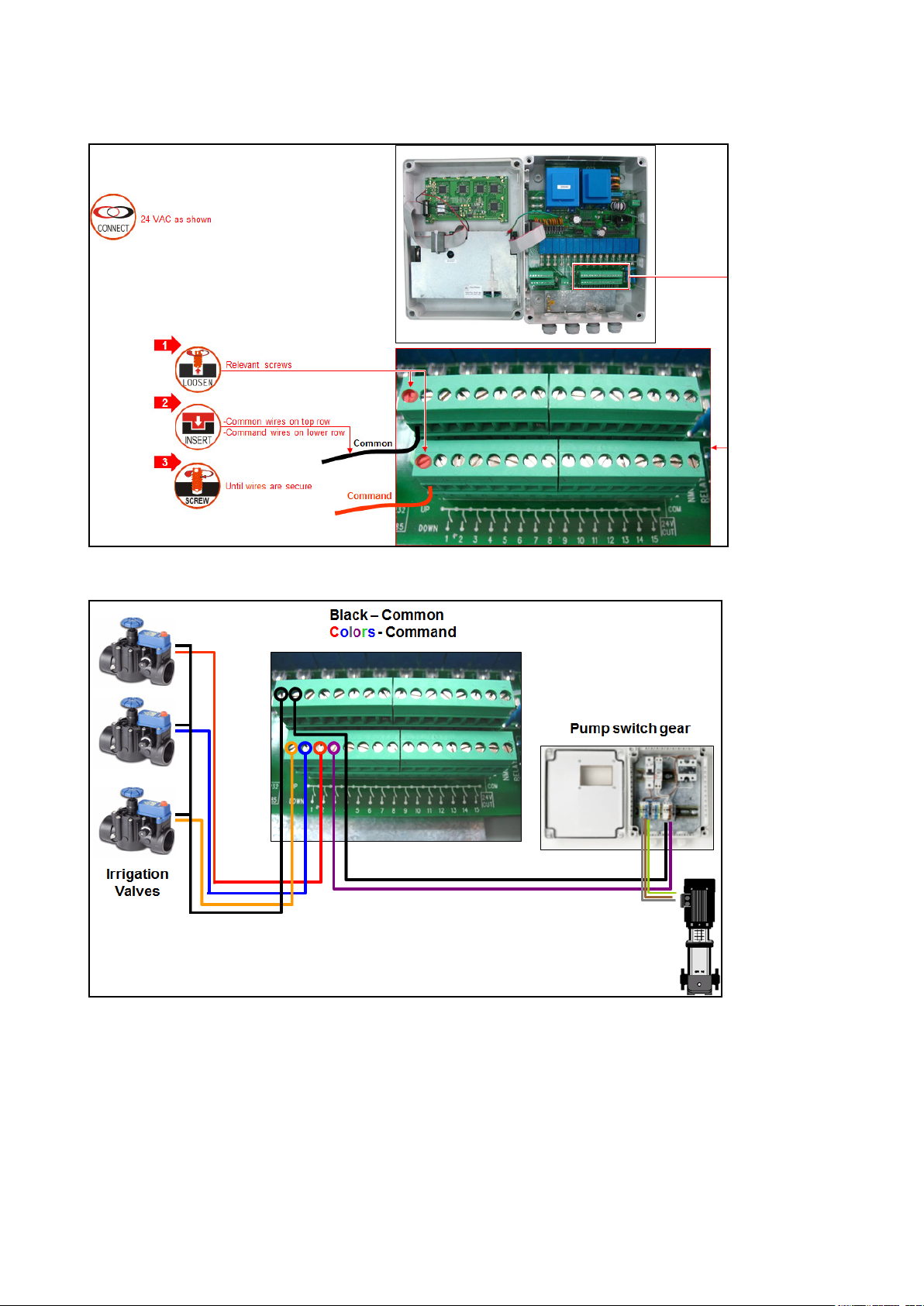
4.2.1 O
UTPUT TERMINAL WIRING
4.2.2 E
XAMPLE OF OUTPUT WIRING
NOTE Before switching the controller on, the technician should verify that there is no short circuit on
each output. (Resistance test)
4.3 Input Terminals
•
Input Terminal Wiring
•
Digital Input Examples
© Munters AB, 2018 17
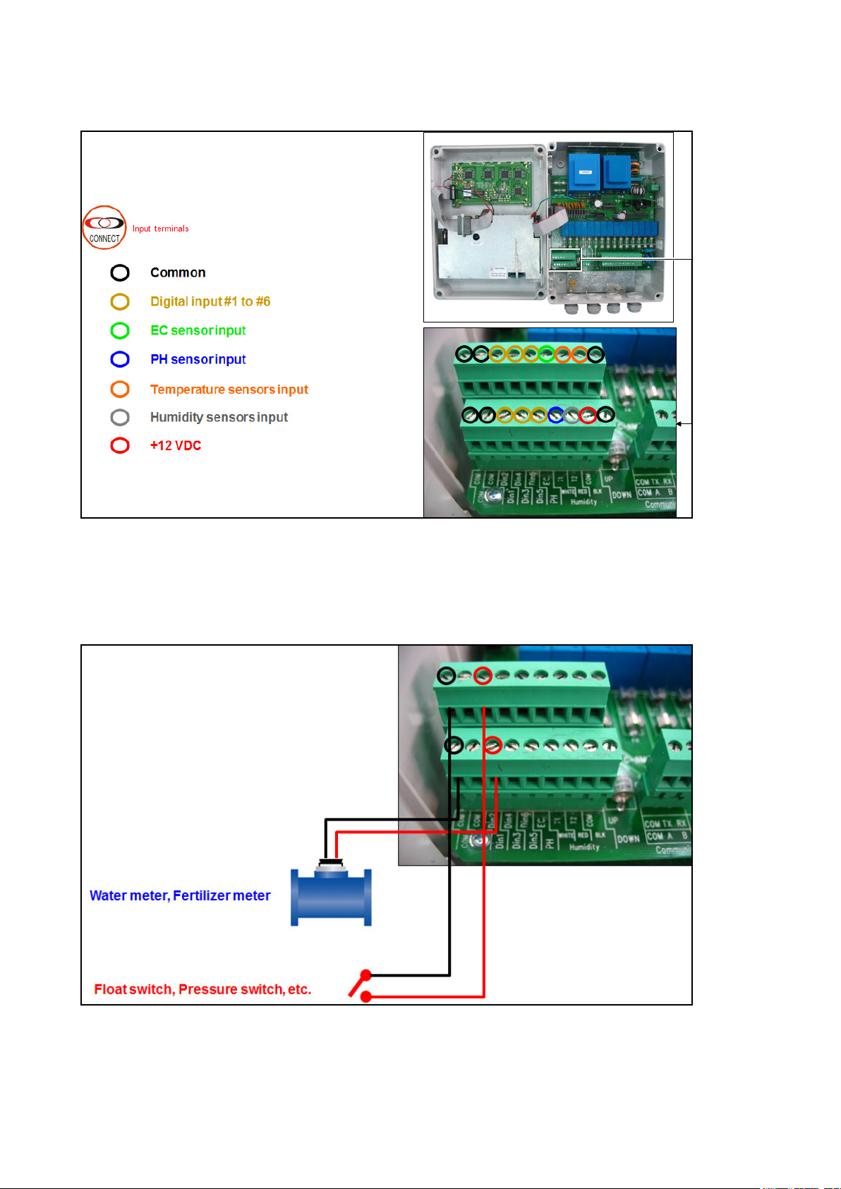
4.3.1 I
NPUT TERMINAL WIRING
4.3.2 D
•
IGITAL INPUT EXAMPLES
Example A
o
Digital input 1: Water meter, Fertilizer meter
o
Digital input 2: Float switch, Pressure switch
o
Digital Input 3: Water Meter with Photo-Diode Output
© Munters AB, 2018 18
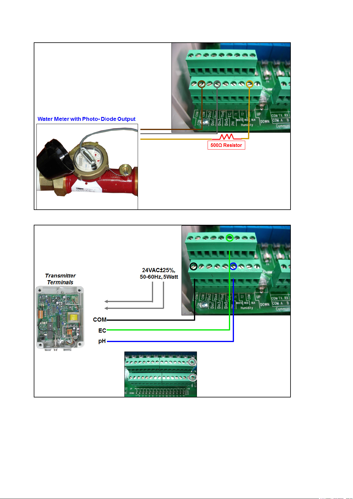
•
Example B: EC / pH sensors
NOTE Can wire EC/pH main power source to 24VAC on the output terminals.
•
Example C: Temperature / Humidity Sensors
© Munters AB, 2018 19
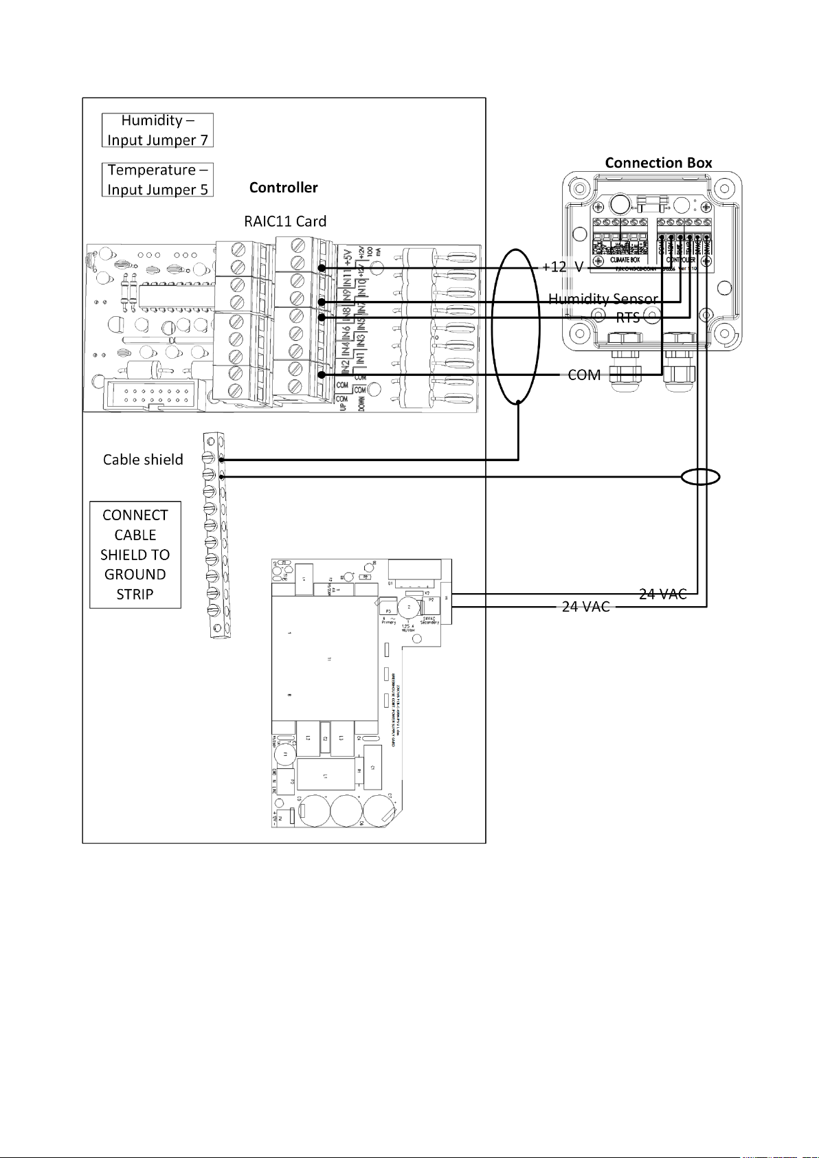
NOTE Can wire 24VAC source in same way as on previous page.
4.4 PC and Inter-Controller Communication
•
Card Installation
•
Wiring and Controller Setup
© Munters AB, 2018 20
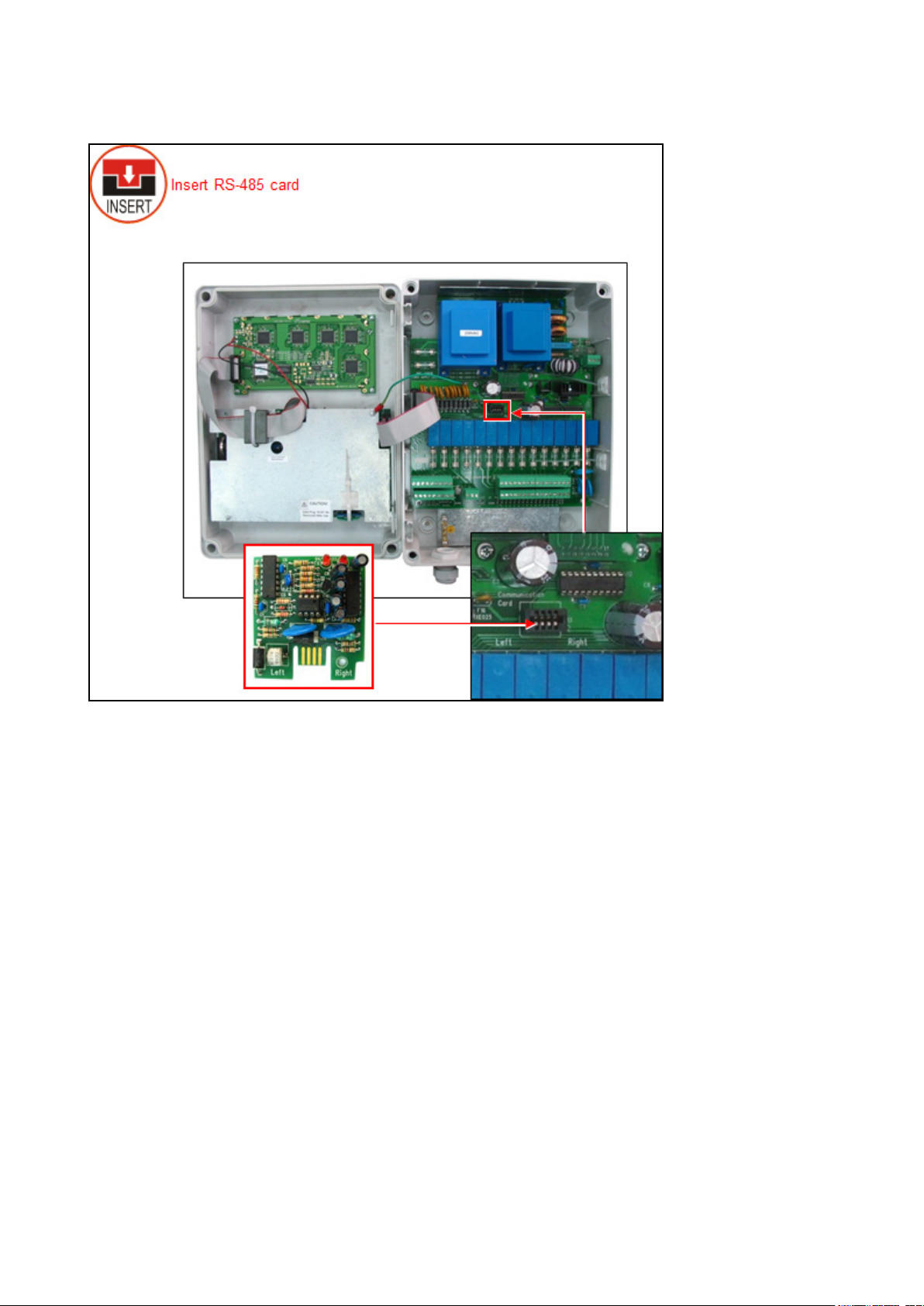
4.4.1 C
ARD INSTALLATION
© Munters AB, 2018 21

4.4.2 W
IRING AND CONTROLLER SETUP
The wiring is detailed in following table:
Number Color Wire
1 Red
2 Black
3 White
4 Green
5 Brown
COM Port Shield wire
Figure 1: RS-485 Wiring to Comm-Box
NOTE Refer to the Comm-Box Manual on wiring details, how to log-on to the Comm-Box and manage
the controller.
© Munters AB, 2018 22

Baud Rate
One Controller
10 Controllers
9600 BPS
4800 BPS
2400 BPS
COMMUNICATION DISTANCE AND BAUD RATE
2000 meter
1.25 mile
2500 meter
1.55 mile
3000 meter
1.86 mile
1200 meter
0.75 mile
1800 meter
1.12 mile
2400 meter
1.49 mile
NOTE Baud rate is dependent on cable length and number of controllers.
© Munters AB, 2018 23
INSTALL ATION
5 Controller Setup
•
Start-Up
•
Device Layout
•
Device List
•
Digital Input
•
Analog Input
•
Hot Keys and Status Screens
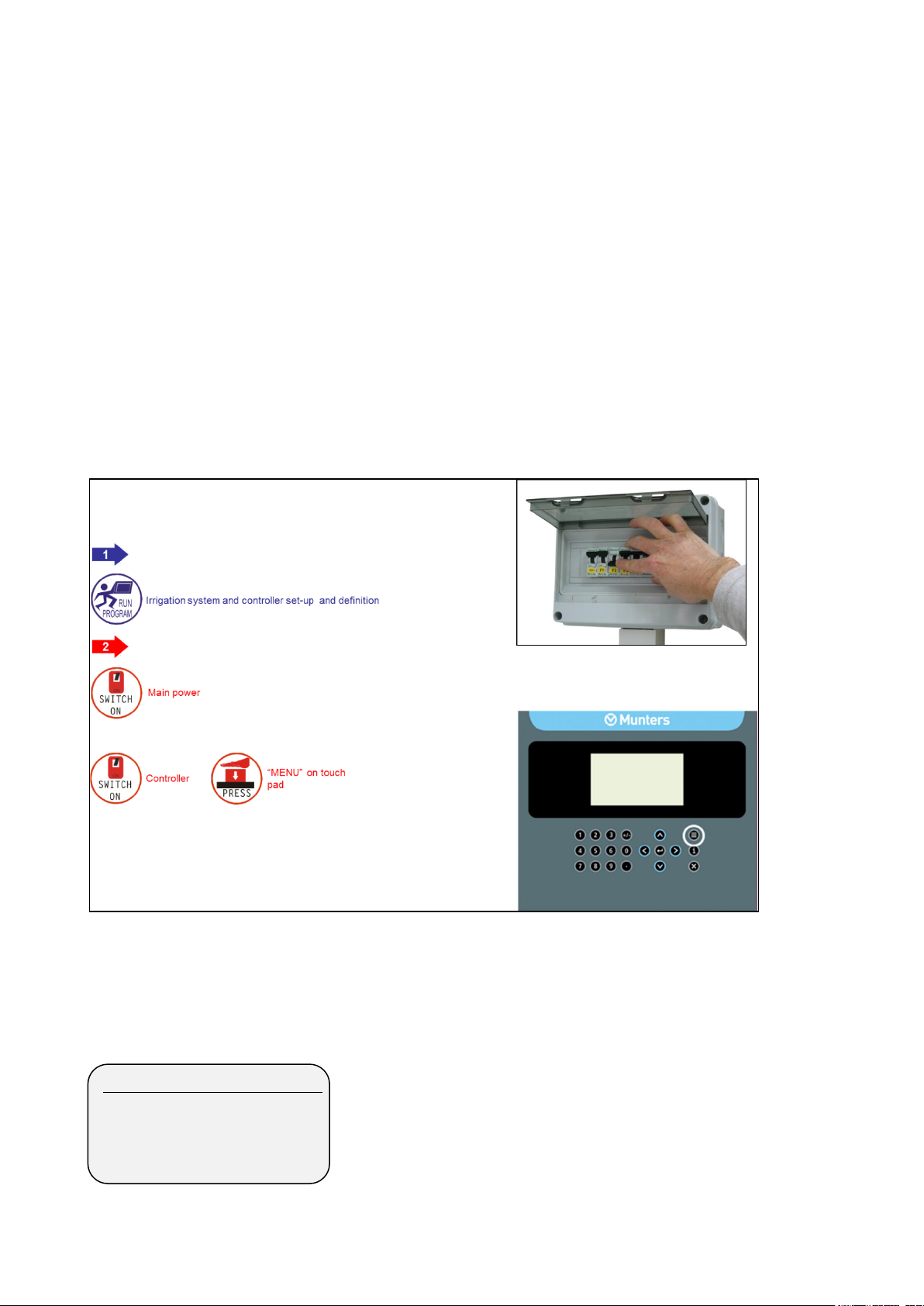
5.1 Start-Up
•
Device Layout, page 24
•
Device List, page 25
•
Digital Input, page 26
5.2 Device Layout
1. DEVICE LAYOUT
2. DEVICE LIST
3. DIGITAL INPUT
4. ANALOG INPUT
The device layout screen allows you to assign functions to each output (relay).
© Munters AB, 2018 24
DEVICE LAYOUT
Relay
Function
No
1
Valve
99
2
Valve
00
3
Valve
01
4
Valve
02
5
Valve
03
6
Valve
04
7
Valve
05
8
None
--
9
Valve
06
10
Pump
1
1. Place the cursor on the Function column, use the arrow keys to reach the relevant line, and press
. A selection list including all available devices will appear.
2. Choose the required device and confirm by pressing . The cursor will move to the No.
column.
3. Specify the number of the device in the controller and press to confirm.
4. If you wish to define several devices of the same type, for example valves 1 to 10, configure the
first one and press a few times until you reach the required amount. The Green Field ECO
automatically continues with the same device until instructed otherwise, or until reaching the system
limitation for that device.
NOTE If 'Radio' is selected in table 6.2, the screen contains at least 64 outputs.
NOTE After making changes, be sure to exit and return again to check for errors. The Green Field ECO
will delete and replace conflicting assignments with ‘---‘.
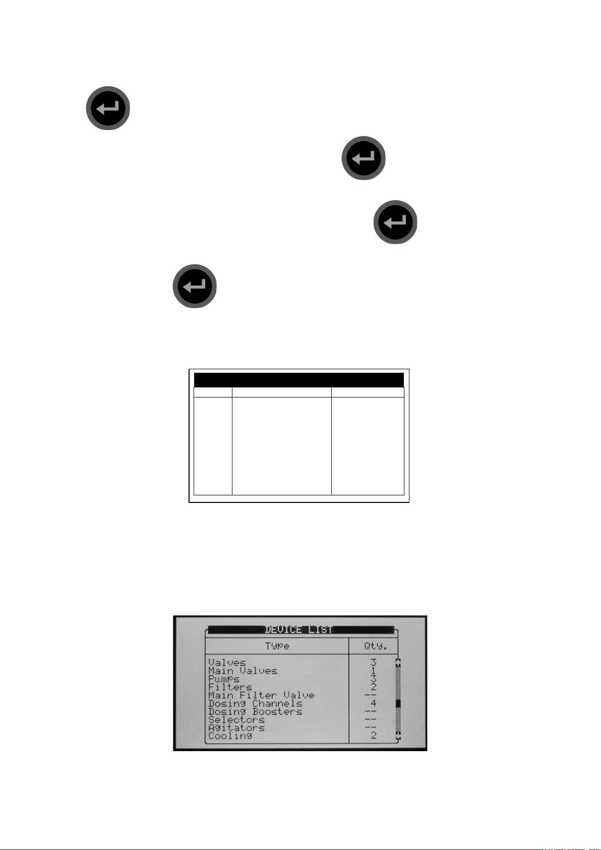
5.3 Device List
The Device List screen allows you to view what type, and how many devices are currently defined.
This screen automatically updates depending on the devices set in the 7.1 screen.
© Munters AB, 2018 25
a. Enter the beginning and ending time for each program.
DIGITAL INPUT
D-In
Input Function
1
Water Meter 1
2
Dosing Meter 1
3
Dosing Meter 2
4
< None >
5
< None >
6
Water Meter 2
Channel
Input Function
Valid
1
pH Sensor
NO
2
EC Sensor
YES
3
Humidity Sensor
YES
4
Temp. Sensor 1
YES
5
Temp. Sensor 2
YES
5.4 Digital Input
1. Go to Installation > Digital Input
2. Place the cursor on the relevant line and press . A selection list will open. Choose the
required sensor and press to confirm.
•
Inputs 1-32 are according to the following:
•
Card no. 1: inputs 1 – 8
•
Card no. 2: inputs 9 – 16
•
Card no. 3: inputs 17 – 24
•
Card no. 4: inputs 25 - 32
5.5 Analog Input
1. In
Installation > Analog Input
2. In
Setup > Analog Conversion Table
a. Select the sensor type
b. Under Valid, select YES.
, define input function(s) as Analog Sensors.
ANALOG INPUT
:
© Munters AB, 2018 26
3. In
Test > Analog Sensor
4. In
Program > Ext Condition
, view the actual sensor values.
, configure the External Condition Program for the analog sensors.
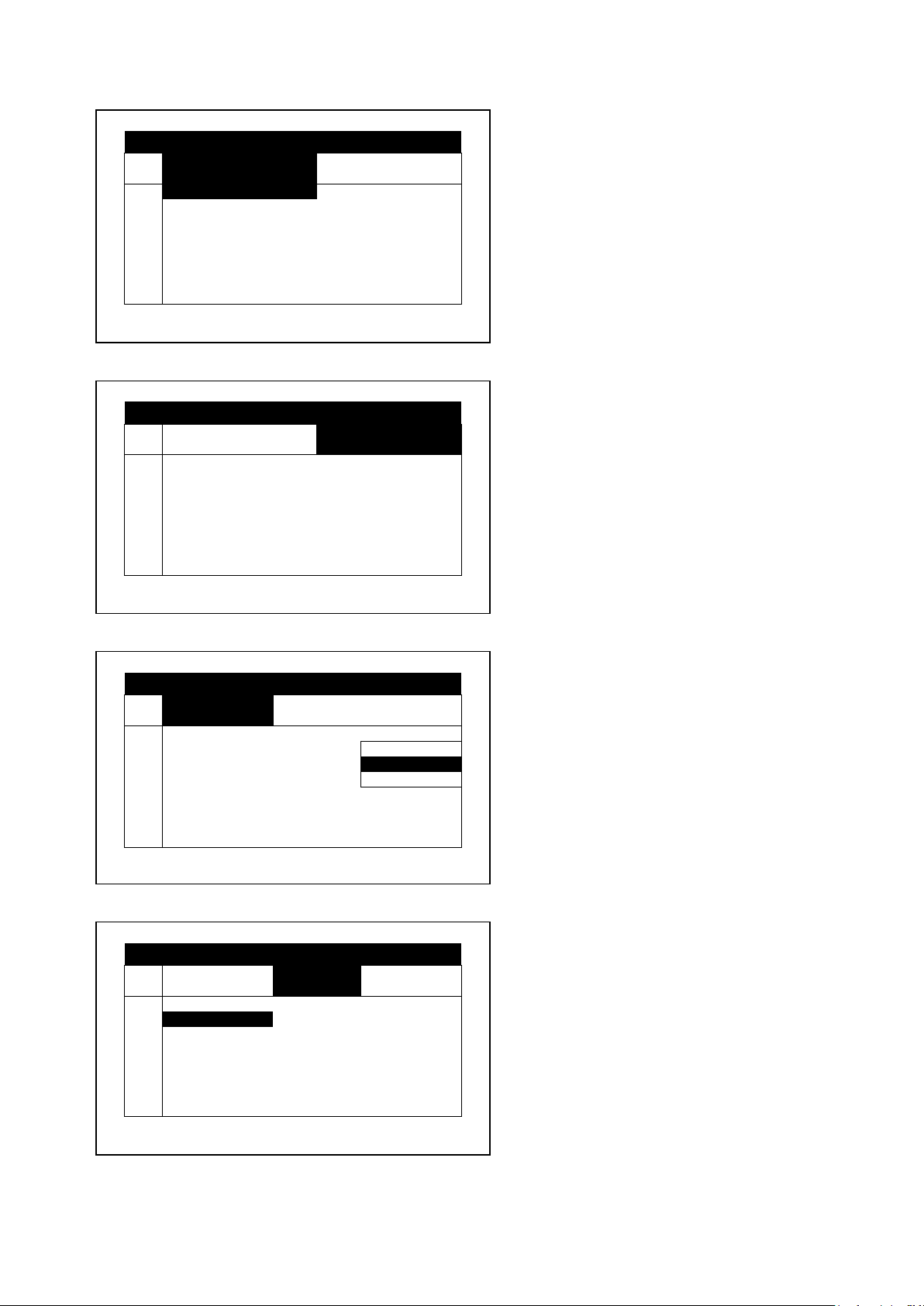
b. Under Start An. Dry Cont., define the input type.
c. Define The Trigger Type
d. Under Stop An. Dry Con., define the input type.
e. Under Oper. to Start, choose the required symbol.
EXTERNAL CONDITION PROGRAM
#
From
hh:mm
To hh:mm
Start An.
Dry Cont.
1
10:00
12:00
2
11:00
12:00
Dry Con 1
3
12:00
13:00
Dry Con 1
4
--:--
--:--
<NONE>
5
--:--
--:--
<NONE>
6
--:--
--:--
<NONE>
7
--:--
--:--
<NONE>
8
--:--
--:--
<NONE>
EXTERNAL CONDITION PROGRAM
#
From
hh:mm
To
hh:mm
Start An.
Dry Cont.
1 12:00
2 12:00
Dry Con 1
3 13:00
Dry Con 1
4 --:--
<NONE>
5 --:--
<NONE>
6 --:--
<NONE>
7 --:--
<NONE>
8 --:--
<NONE>
#
Trigger Type
Stop An
Dry Cont.
Oper.
to Start
1
Multi Shot
---
2
Multi Shot
Dry Con 2
One Shot
3
One Shot
Dry Con 14
Multi Shot
4
One Shot
<NONE>
Only If On
5
One Shot
<NONE>
---
6
One Shot
<NONE>
---
7
One Shot
<NONE>
---
8
One Shot
<NONE>
---
EXTERNAL CONDITION PROGRAM
#
Trigger Type
Stop An
Dry Cont.
Oper.
to Start
1
---
2 Dry Con 2
---
3 Dry Con 14
---
4 <NONE>
---
5 <NONE>
---
6 <NONE>
---
7 <NONE>
---
8 <NONE>
---
EXTERNAL CONDITION PROGRAM
© Munters AB, 2018 27
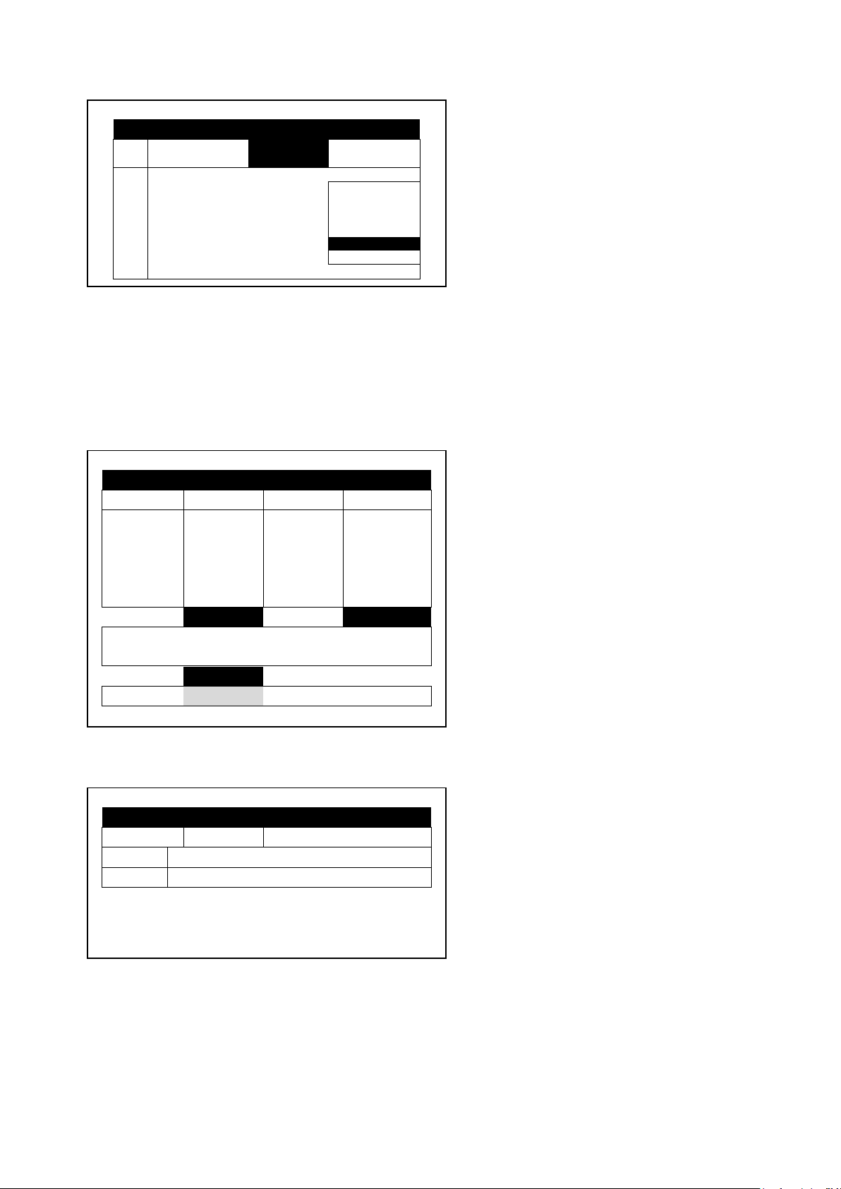
f. Under Start Value, enter the required value to start the analog sensor. Under Stop Value, entered the
EXTERNAL CONDITION PROGRAM
#
Stop An
Dry Cont.
Oper.
to Start
Start
Value
1
<NONE> >
2
Dry Con 2
---
3
Dry Con 14
---
4
<NONE>
---
5
<NONE>
---
6
<NONE>
---
7
<NONE>
---
8
<NONE>
---
SYSTEM SETUP
WATER
00:10:00
00:10:00
FLOW
100.00
100.00
pH 5.3
VALVE:
03-Apr-13
ALARM
MESSAGE
Set
Actual
Flow
Valve
Water
required value to stop the analog sensor.
5.6 Hot Keys and Status Screens
Hot Key 1: Next Irrigation
SET ACTUAL
CYCLE 1 1 START AT
EC 1.5 LEFT
STATUS ACTIVE
PROGRAM: 07:43:23 IRRIGATION
Hot Key 2: Irrigation Process
IRRIGATION PROCESS
Prog: Valve: Time: 08:07:23
© Munters AB, 2018 28
PROGRAM STATUS
13
Status
Wait
Time - Minimum
---
Measured/Limit
Given/Set
Time
Last Start
12:00
Elapsed Time
3:00
Next Start
15:43
WATER
EC/pH
Status
Wait
EC
pH
Nom. Flow
------
Target
---
---
Act. Flow
------
Actual
---
--- Open(%)
Min(%)
Prg(%)
Max(%)
Chan. 1
---
---
---
---
Chan. 2
---
---
---
---
Chan. 4
---
---
---
---
Hot Key 3: Program Status
Program: 1 3-Apr-
Time - Maximum ---
Rad Sum –
Clock Starts –
Starts Due to Rad
Sum
Starts Due to Max
Total Cycles Given 1
09:12:35
—/—
—/—
---
---
Hot Key 4: Water Flow & EC/pH Status
Chan. 3 --- --- --- ---
© Munters AB, 2018 29
FILTER FLUSHING STATUS
Time to Next Flush
--:--:--
Delta Pressure (Digital)
OFF
Remaining Filters Qty.
0
Delay
00:00
1
<NONE>
<NONE>
AVG.
<NONE>
<NONE>
Sen#T
H VPD
VPD SUM
<NONE>
0.0
Hot Key 5: Filter Flushing Status
Item
Flush Status OFF
Flushing Filter No. --
Current Delta Pressure ----
Hot Key 6: Temperature and Humidity Status
TEMP & HUMIDITY
No. Temp. Humidity
2 <NONE> ----
© Munters AB, 2018 30
 Loading...