

Page 1
Manual for installation
Green Box
T+H
Green Box T+H
Humidity and Temperature Sensor
Ag/MIS/UmEN-2738-05/19 Rev 1.2
P/N: 116791
Page 2

Green Box T+H
Manual for use and maintenance
Rev 1.2, 11/2020
This manual for use and maintenance is an integral part of the apparatus together with the attached
technical documentation.
This document is destined for the user of the apparatus: it may not be reproduced in whole or in part,
committed to computer memory as a file or delivered to third parties without the prior authorization of the
assembler of the system.
Munters reserves the right to effect modifications to the apparatus in accordance with technical and legal
developments.
© Munters AB, 2018 2
Page 3

Index
chapter page
1
INTRODUCTION ------------------------------------------------------------------------------------------------------------------------------------------ 4
1.1 Disclaimer
1.2 Introduction
1.3 Notes
2
INTRODUCTION TO THE GREEN BOX ------------------------------------------------------------------------------------------------ 5
2.1 Green Box Positioning
2.2 Green Box Installation
2.3 Green Box Connection Specifications
3
MAINTENANCE ------------------------------------------------------------------------------------------------------------------------------------------- 9
3.1 Temperature Sensor
3.2 Humidity Sensor
3.3 Fan Replacement
3.4 Fuse Replacement
4
SPECIFICATIONS -------------------------------------------------------------------------------------------------------------------------------------- 12
--------------------------------------------------------------------------------------------------------------------------------------------------------------------------------
-----------------------------------------------------------------------------------------------------------------------------------------------------------------------------
-----------------------------------------------------------------------------------------------------------------------------------------------------------------------------------------
-----------------------------------------------------------------------------------------------------------------------------------------------------
-----------------------------------------------------------------------------------------------------------------------------------------------------
-------------------------------------------------------------------------------------------------------------------
----------------------------------------------------------------------------------------------------------------------------------------------------------
-------------------------------------------------------------------------------------------------------------------------------------------------------------------
--------------------------------------------------------------------------------------------------------------------------------------------------------------
------------------------------------------------------------------------------------------------------------------------------------------------------------
10
11
4
4
4
5
6
6
9
9
4.1 Cable Specifications
4.2 Temperature Sensor Specifications
4.3 Temperature Sensor Connections
4.4 Humidity Sensor Specifications
5
APPENDIX: WIRING INFORMATION ------------------------------------------------------------------------------------------------ 13
6
WARRANTY ------------------------------------------------------------------------------------------------------------------------------------------------- 14
------------------------------------------------------------------------------------------------------------------------------------------------------
-----------------------------------------------------------------------------------------------------------------------
--------------------------------------------------------------------------------------------------------------------------
-------------------------------------------------------------------------------------------------------------------------------
12
12
12
12
© Munters AB, 2018 3
Page 4

1 Introduction
1.1 Disclaimer
Munters reserves the right to make alterations to specifications, quantities, dimensions etc. for production or
other reasons, subsequent to publication. The information contained herein has been prepared by qualified
experts within Munters. While we believe the information is accurate and complete, we make no warranty
or representation for any particular purposes. The information is offered in good faith and with the
understanding that any use of the units or accessories in breach of the directions and warnings in this
document is at the sole discretion and risk of the user.
1.2 Introduction
Congratulations on your excellent choice of purchasing a Green Box!
In order to realize the full benefit from this product it is important that it is installed, commissioned and
operated correctly. Before installation or using the fan, this manual should be studied carefully. It is also
recommended that it is kept safely for future reference. The manual is intended as a reference for installation,
commissioning and day-to-day operation of the Munters Controllers.
1.3 Notes
Date of release: July 2019
Munters cannot guarantee to inform users about the changes or to distribute new manuals to them.
All rights reserved. No part of this manual may be reproduced in any manner whatsoever without the
expressed written permission of Munters. The contents of this manual are subject to change without notice.
© Munters AB, 2018 4
Page 5

2 Introduction to the Green Box T+H
The Munters Green Box T+H is used to improve temperature and/or humidity measurement in a greenhouse
or in any application requiring this data and when:
•
solar radiation can affect the results
•
microclimates can form
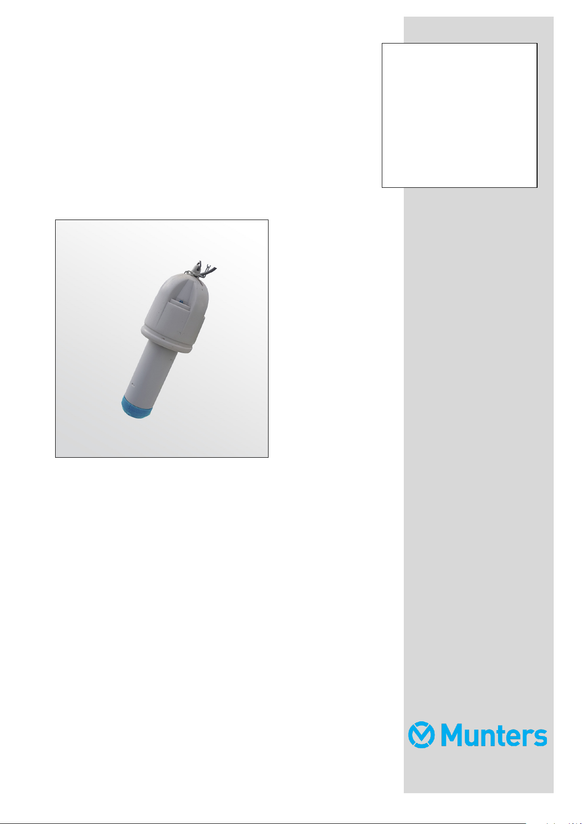
The Green Box (Figure 1) consists of a:
•
plastic enclosure connected to a cable
•
6-wire cable
•
fan
•
temperature and humidity sensor
In addition, the unit comes with:
•
Connection Box (Figure 2), connected to a 6-wire 10.5 meter cable
•
Five meter chain (attached to the Green Box cable)
•
S Hook
•
Two mounting brackets
•
Two roundhead screws (use these to attach the mounting brackets to the Connection Box)
•
Two flathead screws (use these to attach the mounting brackets to a wall/wood sheet)
2.1 Green Box Positioning
Position the Green Box in a representative spot. Choose a location that is not highly vulnerable so the
Green Box isn't damaged, for example not too close to a heater or to the path.
•
In short crops it is recommended to position the Green Box about 30 cm (12 inches) above the
crop, in an area that is relatively not influenced by metal and other irrelevant factors like a path,
sprayer, etc.
•
In tall crops it is recommended to position the Green Box around the middle of the crop height,
in an area that is relatively not influenced by metal and other irrelevant factors like a path,
sprayer, etc.
© Munters AB, 2018 5
Page 6

2.2 Green Box Installation
1. Using the supplied chain, hang the Green Box in the required location. Use the supplied S hook.
2. Using the supplied clips, install the Connection Box in the required location.
CAUTION The Connection Box has a 10.5 meter cable that connects it to the Green Box. Make sure that
you install the Connection Box within this distance to the Green Box.
NOTE If you place the Green Box in a high position (high crops) make sure to leave enough cable so that
the Green Box can be lowered down for maintenance purposes.
3. The Green Box and Connection Box come with the wiring installed. The user needs to wire the
Connection Box to the controller analog input card and power supply (Figure 3).
CAUTION Do not use electrical cable to hang the unit!
2.3 Green Box Connection Specifications and Wiring
The Green Box is wired to the controller using a 6-wire shielded cable as follows:
•
24 VAC for the fan
•
24 VAC for the fan
•
Temperature output
•
Relative humidity output
•
12 VDC for the RH sensor
•
Common
Figure 1: Green Box unit Figure 2: Connection Box
© Munters AB, 2018 6
Page 7

1. Wire the Connection Box to the controller as shown in Figure 3.
Figure 3: Controller / Connection Box wiring diagram
NOTE The above diagram is an example only. The RTS and Humidity Sensor can be wired to any RAIC11
input port.
NOTE The shield should be connected to the ground on one side only.
© Munters AB, 2018 7
Page 8

2. Strip the Connection Box shield cables and wrap them together as shown in Figure 4.
Figure 4: Connection Box shield cables wrap
© Munters AB, 2018 8
Page 9

3 Maintenance
Periodically inspect the fan for excess dust build up.
3.1 Temperature Sensor
The temperature sensor requires no maintenance.
3.2 Humidity Sensor
This procedure describes how to replace the humidity sensor head assembly.
1. Unscrew the box tip and locate the humidity sensor.
Figure 5: Box tip removed
2. Untwist the filter.
Figure 6: Filter
3. Pull out the sensor assembly.
Figure
© Munters AB, 2018 9
:7
Sensor assembly
Do not touch the sensor element!
4. Remove the Sensor Tip.
Page 10

Figure
:8
Sensor Tip
5. Put a new Sensor tip in place and replace the filter.
NOTE Note: Insert the Sensor Tip gently, with the pins going in completely. If the Sensor Tip does not go
in completely, pull it out, turn it over and reinsert.
3.3 Fan Replacement
Figure
:9
Unit fan
1. Disconnect the fan's red and black wires from the wire connectors.
2. Unscrew the fan, remove the unit, and place the new unit in place.
3. Connect the fan's red and black wire to the wire connector:
o
Black wire is inserted into the connector opposite the blue wire.
o
Red wire is inserted into the connector opposite the brown wire.
© Munters AB, 2018 10
Page 11

3.4 Fuse Replacement
The Connection Box comes equipped with a 160 mA fuse. In addition, Munters provides a spare fuse (in
a small plastic bag).
Figure
:10
Fuse location
1. Disconnect the Connection Box' power supply.
2. Open the Box, remove the fuse, and replace it with the spare.
3. Recover the box and apply power.
© Munters AB, 2018 11
Page 12

4 Specifications
4.1 Cable Specifications
Sensor Cable Type: 4 Wire Shielded Cable, 22 AWG (minimum)
24V Cable Type 2 Wire Shielded Cable, 22 AWG (minimum)
Maximum Cable Length (between the controller and
Connection Box):
WARNING: TO ENSURE INTERFERENCE AND LIGHTNING IMMUNITY, USE SHIELDED CABLE
ONLY!
WARNING: POWER AND SIGNAL WIRES MUST BE IN SEPARATE CABLES!
300 meter (985 feet)
4.2 Temperature Sensor Specifications
Type: 30K Ohm Thermistor at (25° C)
Curve Number: 1
Maximum 25°C Tolerance: ±3%
Operating Temperature: 0° to +60° C
4.3 Temperature Sensor Connections
Red: Output 30kOHM
Black: Common
Shield: Safety Ground
4.4 Humidity Sensor Specifications
Input voltage 8 – 14 VDC
Output voltage 0 – 3 VDC
Typical accuracy tolerance at 25° C and 0 – 100%
relative humidity
Maximum accuracy tolerance at 25° C and 90 –
100% relative humidity
Temperature range 0 - 80° C
© Munters AB, 2018 12
±2%
±3.5
Page 13

Temperature Sensor
Humidity Sensor
24 VDC Fan
6-Wire Cable (Short cable)
6 Wire Cable (10 meter)
Green Box Terminal
5 Appendix: Wiring Information
In the event that you need to rewire the Green Box to the Connection Box, use the following tables as a
guide.
Table 1: Green Box Wiring
Black Black — Black
Red Green (N.C.) — Green
— Red — Red
— — Black Blue
— — Red Brown
— White — White
Shield (N.C) Shield (N.C) — Shield (N.C)
Table 2: Connection Box Wiring
Black COM
Green Temperature
Red +12V
Blue Fan –
Brown Fan +
White RH
Shield (N.C) —
© Munters AB, 2018 13
Page 14

6 Warranty
Warranty and technical assistance
Munters products are designed and built to provide reliable and satisfactory performance but cannot be
guaranteed free of faults; although they are reliable products they can develop unforeseenable defects and
the user must take this into account and arrange adequate emergency or alarm systems if failure to operate
could cause damage to the articles for which the Munters plant was required: if this is not done, the user is
fully responsible for the damage which they could suffer.
Munters extends this limited warranty to the first purchaser and guarantees its products to be free from
defects originating in manufacture or materials for one year from the date of delivery, provided that suitable
transport, storage, installation and maintenance terms are complied with. The warranty does not apply if
the products have been repaired without express authorisation from Munters, or repaired in such a way
that, in Munters’ judgement, their performance and reliability have been impaired, or incorrectly installed,
or subjected to improper use. The user accepts total responsibility for incorrect use of the products.
The warranty on products from outside suppliers fitted to Green Box, (for example Green Box’ power
supplies, cables, etc.) is limited to the conditions stated by the supplier: all claims must be made in writing
within eight days of the discovery of the defect and within 12 months of the delivery of the defective product.
Munters has thirty days from the date of receipt in which to take action, and has the right to examine the
product at the customer’s premises or at its own plant (carriage cost to be borne by the customer).
Munters at its sole discretion has the option of replacing or repairing, free of charge, products which it
considers defective, and will arrange for their despatch back to the customer carriage paid. In the case of
faulty parts of small commercial value which are widely available (such as bolts, etc.) for urgent despatch,
where the cost of carriage would exceed the value of the parts, Munters may authorise the customer
exclusively to purchase the replacement parts locally; Munters will reimburse the value of the product at its
cost price.
Munters will not be liable for costs incurred in demounting the defective part, or the time required to travel
to site and the associated travel costs. No agent, employee or dealer is authorised to give any further
guarantees or to accept any other liability on Munters’ behalf in connection with other Munters products,
except in writing with the signature of one of the Company’s Managers.
WARNING: In the interests of improving the quality of its products and services, Munters reserves the right
at any time and without prior notice to alter the specifications in this manual.
© Munters AB, 2018 14
Page 15

The liability of the manufacturer Munters ceases in the event of:
dismantling the safety devices;
•
use of unauthorised materials;
•
inadequate maintenance;
•
use of non-original spare parts and accessories.
•
Barring specific contractual terms, the following are directly at the user’s expense:
preparing installation sites;
•
providing an electricity supply (including the protective equipotential bonding (PE) conductor, in
•
accordance with CEI EN 60204-1, paragraph 8.2), for correctly connecting the equipment to the
mains electricity supply;
providing ancillary services appropriate to the requirements of the plant on the basis of the
•
information supplied with regard to installation;
tools and consumables required for fitting and installation;
•
lubricants necessary for commissioning and maintenance.
•
It is mandatory to purchase and use only original spare parts or those recommended by the manufacturer.
Dismantling and assembly must be performed by qualified technicians and according to the manufacturer’s
instructions.
The use of non-original spare parts or incorrect assembly exonerates the manufacturer from all liability.
Requests for technical assistance and spare parts can be made directly to the nearest Munters office. A full
list of contact details can be found on the back page of this manual.
Munters Israel
18 HaSivim Street
Petach-Tikva 49517, Israel
Telephone: +972-3-920-6200
Fax: +972-3-924-9834
© Munters AB, 2018 15
Page 16

Ag/MIS/UmEN-2736-05/19 Rev 1.2
www.munters.com
Australia Munters Pty Limited, Phone +61 2 8843 1594, Brazil Munters Brasil Industria e Comercio Ltda, Phone +55 41 3317 5050, Canada Munters Corporation
Lansing, Phone +1 517 676 7070, China Munters Air Treatment Equipment (Beijing) Co. Ltd, Phone +86 10 80 481 121, Denmark Munters A/S, Phone +45 9862
3311, India Munters India, Phone +91 20 3052 2520, Indonesia Munters, Phone +62 818 739 235, Israel Munters Israel Phone +972-3-920-6200, Italy Munters
Italy S.p.A., Chiusavecchia, Phone +39 0183 52 11, Japan Munters K.K., Phone +81 3 5970 0021, Korea Munters Korea Co. Ltd., Phone +82 2 761 8701, Mexico
Munters Mexico, Phone +52 818 262 54 00, Singapore Munters Pte Ltd., Phone +65 744 6828, South Africa and Sub-Sahara Countries Munters (Pty) Ltd., Phone
+27 11 997 2000, Spain Munters Spain S.A., Phone +34 91 640 09 02, Sweden Munters AB, Phone +46 8 626 63 00, Thailand Munters Co. Ltd., Phone +66 2
642 2670, Turkey Munters Form Endüstri Sistemleri A.Ş, Phone +90 322 231 1338, USA Munters Corporation Lansing, Phone +1 517 676 7070, Vietnam Munters
Vietnam, Phone +84 8 3825 6838, Export & Other countries Munters Italy
S.p.A., Chiusavecchia Phone +39 0183 52 11
 Loading...