

Page 1

Instruction Manual
GB Series
'M' and 'H' Fans
18” - 48”
'M' Fan
'H' Fan
GB Series 'M' and 'H' Fan
18” - 48”
Models: GB18M • GB18H • GB24M • GB24H •
GB36Mx • GB36Hx • GB365Mx • GB365Hx •
GB48xMx • GB48xHx
QM1061r1
1© Munters Corporation, February 2019
Page 2

GB Series 'M' and 'H' Fan 18” - 48”
Instructions for Use and Maintenance
Thank You:
Thank you for purchasing a GB Series 'M' or 'H' Fan. Munters equipment is designed to be the highest
performing, highest quality equipment you can buy. With the proper installation and maintenance it will provide
many years of service.
Please Note:
To achieve maximum performance and insure long life from your Munters product it is essential that it be
installed and maintained properly. Please read all instructions carefully before beginning installation.
Warranty:
For Warranty claims information see the “Warranty Claims and Return Policy” form QM1021 available from the
Munters Corporation office at 1-800-227-2376 or by e-mail at aghort.info@munters.com.
Conditions and Limitations:
• Products and Systems involved in a warranty claim under the “Warranty Claims and Return Policy” shall have
been properly installed, maintained and operated under competent supervision, according to the instructions
provided by Munters Corporation.
• Malfunction or failure resulting from misuse, abuse, negligence, alteration, accident or lack of proper
installation or maintenance shall not be considered a defect under the Warranty
.
2
QM1061r1
© Munters Corporation, February 2019
Page 3

Index
Chapters Page
1. Unpacking the Equipment 4
1.1 Parts List 4
1.2 Dimensions 4
2. Installation Instructions 5
3. Electrical Wiring 6
4. Operation 7
5. Maintenance 8
6. Winterizing 10
7. Troubleshooting 11
8. Exploded View and Parts List 12-14
QM1061r1
3© Munters Corporation, February 2019
Page 4

Unpacking the Equipment
1.
Before beginning installation, check the overall condition of the equipment. Remove packing Materials and
examine all components for signs of shipping damage. Any shipping damage is the customers responsibility and
should be reported immediately to your freight carrier.
1.1 Parts List
Each Crate Includes:
1 - 18”, 24”, 36” or 48” Belt Drive or Direct Drive fan
1 - Hardware Package (HP1044) for 'M' fan only
HP1044 – Hardware Package for 'M' Fan
ID Qty. Cat. No. Description
[A] 2 KS2752 ⁵⁄₁₆"-18 x 2" Closed Eyebolt with Nut, ZP
[B] 2 KN1706 ⁵⁄₁₆"-18 x Nylock Nut, ZP
1.2 Fan Dimensions
Fan Specifications: 60Hz shown (50Hz available)
Power: 120/240 VAC or 208-240/480 VAC
Phase: 1 or 3
C
D
C
A
B
B
A
H-Fan
Wood Crate
Housing, Guards
Dimensions:
Fan
Cat. No.
GB18M 18” Direct Galvanized Steel 221⁄4”22
GB18H 18” Direct Galvanized Steel 23” 23” 15
GB24M 24” Direct Galvanized Steel 281⁄4”28
GB24H 24” Direct Galvanized Steel 29” 29” 15
GB36M 36” Direct Galvanized Steel 421⁄4”42
GB36H 36” Direct Galvanized Steel 43” 43” 151⁄2” - - - 431⁄2” sq.
GB365M 36” Belt Galvanized Steel 421⁄4”42
GB365H 36” Belt Galvanized Steel 43” 43” 15
GB48xM 48” Belt Galvanized Steel 541⁄4”54
GB48xH 48” Belt Galvanized Steel 55” 55” 24” - - - 55
Dia.
Drive
Type Prop. Type A B C D
M-Fan
Galvanized Crate
Housing, Guards
A
Wall Openings
1
⁄4”135⁄8” - - - 221⁄2” sq.
1
⁄2” - - - 231⁄2” sq.
1
⁄4”135⁄8” - - - 281⁄2” sq.
1
⁄2” - - - 291⁄2” sq.
1
⁄4”135⁄8” - - - 43” sq.
1
⁄4”135⁄8” 3” 43” sq.
1
⁄2”27⁄8”43
1
⁄4”171⁄2”15⁄8” 55” sq.
( I.D., Framed)
1
⁄2” sq.
1
⁄2” sq.
4
QM1061r1
© Munters Corporation, February 2019
Page 5
Installation Instructions
2.1 Installation
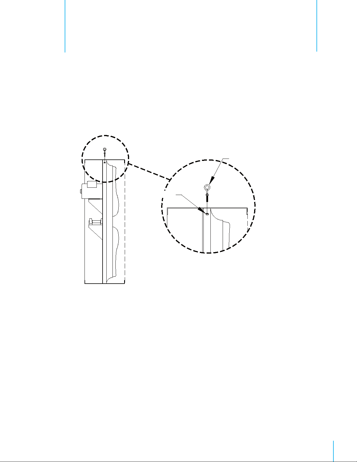
Step 1
Remove rear guard and install (2) Eyebolts [A] and Nuts [B] (provided for 'M' fan). See Figure 1.
Step 2
Proceed to Electrical Wiring Section before replacing guard.
Closed Eyebolt with nut [A]
2.
Nut [B]
Figure 1
QM1061r1
5© Munters Corporation, February 2019
Page 6

Electrical Wiring
3.
All wiring should be installed in accordance with National, State, and Local electrical codes. Fans used to ventilate
livestock buildings or other rooms where continuous air movement is essential should be connected to individual
electrical circuits, with a minimum of two circuits per room. For electrical connection requirements, refer to diagram on
motor nameplate and to information enclosed with the environmental control to be used.
Single Phase Fans
slow blow motor type fuses must be used
Three Phase Fans:
slow blow motor fuses must be used.
If a frequency drive (inverter) is used, confirm that motors are rated for inverter duty at the voltage used. The
installation of line reactors is recommended to reduce voltage spikes and harmonic distortion. Supplemental
motor overload protection is also recommended.
: motor overload protection should be provided for each fan. A Circuit Breaker Switch or
See Figure 8A
. See QM1400 for proper size.
motor overload protection should be provided for each fan. A three pole motor starter or
See Figure 8B
.
NOTE: A safety cut-off switch should be located adjacent to each fan.
120 or 240 VAC Power
Supply for Fan
L1 (H)
L2 (N)
G
L1 (H)
L2 (N)
T1 (H)
T2 (N)
Figure 8A
Single Phase - Motor Overload Protection with Disconnect
(SY2000 or Equivalent)
Safety Cut-off Switch
Three Phase Power
Supply for Fan
L1
L2
L3
G
L1
L2
L3
Motor Starter
T1
T2
T3
Figure 8B
KEY:
L1 = Line 1
L2 = Line 2
L3 = Line 3
H = Hot
N = Neutral
G = Ground
Three Phase - Motor Overload Protection with Disconnect
Note::
Information in parenthesis refers to 120 VAC control.
T1 (H)
T2 (N)
G
120 or 240 VAC
Power Out to Fan
T1
T2
T3
G
Three Phase
Power Out
to Fan Motor
6
QM1061r1
© Munters Corporation, February 2019
Page 7
4.1 Operation
Operation
4.
INITIAL START-UP: With electrical power off, verify that the fan propeller turns freely
and that all fasteners are secure. Turn on electrical power and confirm that the fan
operates smoothly.
ADJUSTMENTS: Set the fan control to the temperature shown on your ventilations
system drawing, or to a value which will provide the desired environmental
conditions.
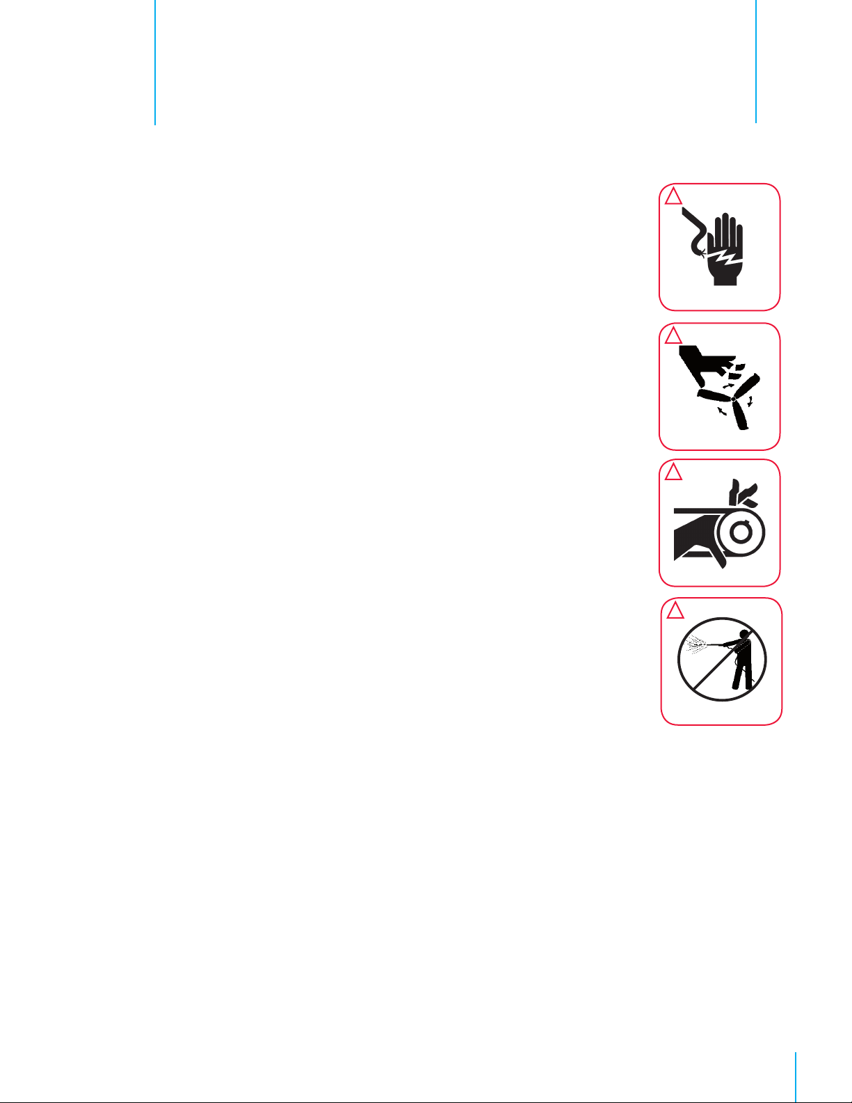
!
WARNING
Disconnect Power
Before Servicing
!
WARNING
Moving Parts, Disconnect
Power Before Servicing.
!
WARNING
Moving Parts: Disconnect
Power Before Servicing.
!
WARNING
Do Not Power Wash
Electrical Devices.
QM1061r1
7© Munters Corporation, February 2019
Page 8
Maintenance
5.1 Maintenance
5.
The following inspection and cleaning procedures should be performed monthly:
Tools Needed for Maintenance:
wrenches: 17mm, 27mm, ⁵⁄₃₂" Allen
1) INSPECT PROPELLER: Check that propeller is secure on prop shaft or motor shaft
and that there are no signs of damage. The blades are of a self-cleaning design
and should not require maintenance.
2) CLEAN regularly for best results:
• FAN MOTOR: Remove any dust accumulation from motor using a brush or
cloth. (DO NOT use a pressure washer). A clean motor will run cooler and last
longer. At the same time, verify that the motor is secure in its mount.
• SHUTTER: Carefully clean dust from damper doors and frame so that doors
open and close freely. A brush or cloth should be used.
• GUARD: Clean any dust or feathers from fan guards using a brush. Dirty
guards can reduce airflow.
3) CHECK FASTENERS: For safety, all fasteners should be inspected 1 month after
initial operation and yearly thereafter. Tighten any loose connections.
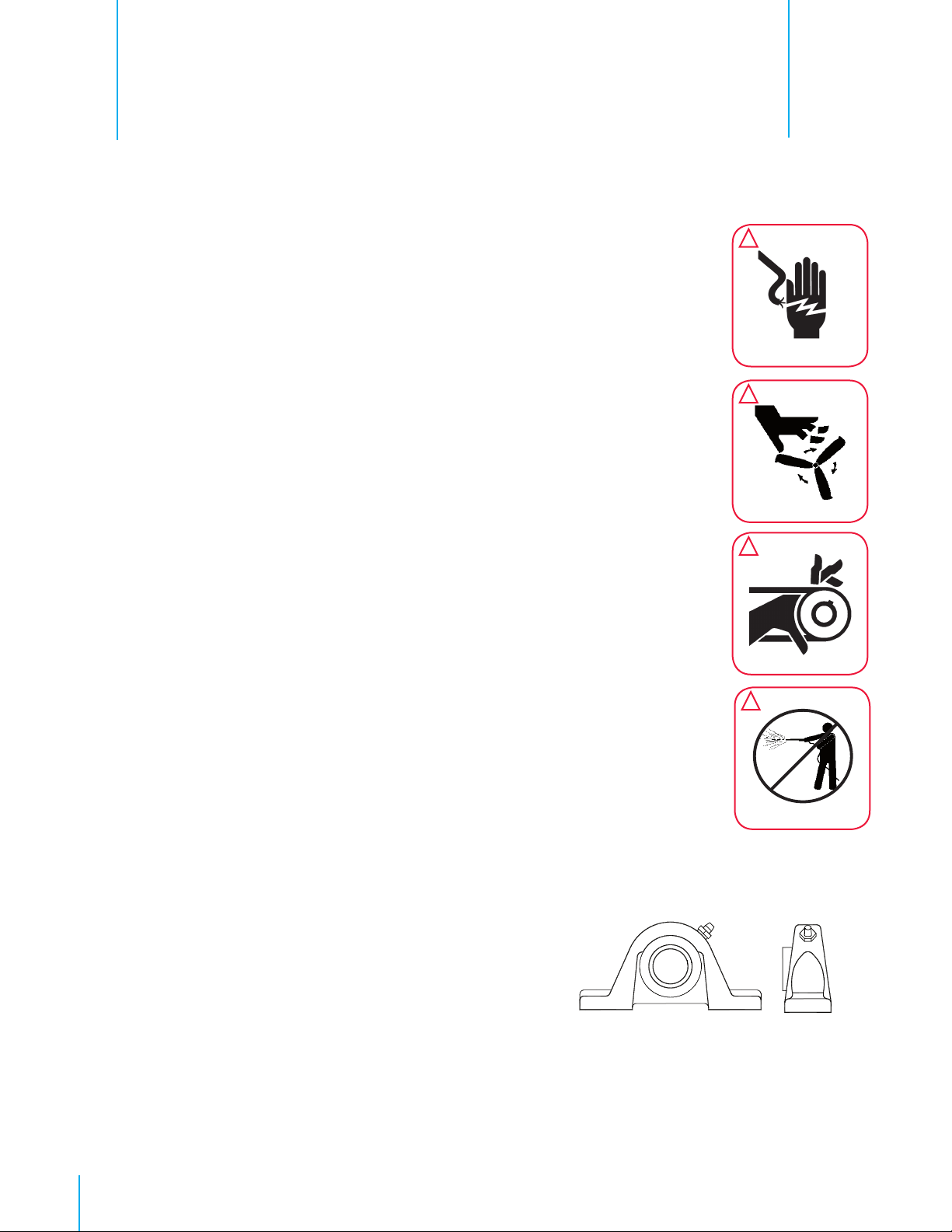
!
WARNING
Disconnect Power
Before Servicing
!
WARNING
Moving Parts, Disconnect
Power Before Servicing.
!
WARNING
Moving Parts: Disconnect
Power Before Servicing.
!
WARNING
8
4) INSPECT FAN CONTROL: With power disconnected, inspect all electrical
connections. Wiring should be secure and in good condition. Remove any dust
build-up from control case and sensor using a soft brush or cloth. NEVER CLEAN
ELECTRICAL EQUIPMENT WITH A PRESSURE WASHER!
5) GREASE BEARINGS: Grease bearings every 4-6 months.
Use no more than 2 shots when greasing fan.
• A premium non-water based grease is recommended:
- Shell Alvania #2 - Mobil Mobilux #2
- Exxon Unirex N2 - Texaco Premium RB
- Mobil 532 - Texaco Multifak #2
QM1061r1
Do Not Power Wash
Electrical Devices.
© Munters Corporation, February 2019
Page 9

MaintenanceChapter 5
6) CHECK DRIVE ALIGNMENT: Check to make sure the belt is
centered on the idler pulley, then use a straight edge to check
the alignment of the drive pulleys. If an adjustment is needed,
remove the belt, then loosen the set screw in one pulley and move
it. Remember to tighten the set screw after making an adjustment.
Drive alignment is very important for long belt life and proper
operation.
7) CHECKING PULLEYS: Roll the belt off and look at both pulleys.
If the pulley has grooves in it or is no longer smooth, it needs
replacement. A loose or slipping belt will reduce fan performance
up to 60% and cause premature belt failure.
8) BELT TENSIONING:
All belts must be checked for proper tension after the first 3 days of
fan operation and every 4-6 months thereafter.
Solid Belt
To adjust the belt tensioner to the proper setting, loosen 10 mm
bolt fastening tensioner to bracket (using 17mm end wrench) to
allow tensioner arm to rotate. Working from inlet/motor side of
fan, place a 27 mm (1
1
⁄16”) wrench onto the hex on the tensioner.
Turn wrench counterclockwise until the single mark on base of the
belt tensioner is aligned with mark 4 on the tensioner arm. Hold
tensioner at this setting and tighten the 10mm bolt to 40 ft. lbs.
[54 N-m] torque.
Propeller
Pulley
Smooth
Pulley
Belt
Straight Edge
Idler
Pulley
Grooved
Pulley
Motor
Pulley
AeroLink Belt
• Roll the belt off the pulleys by forcing it sideways off the
larger pulley as you turn the drive by hand.
• Reinstall the belt by wrapping it around the smaller pulley and
then starting it over the larger pulley.
• As you continue rolling it onto the larger pulley, the belt
should become taut in the position shown below.
• If the belt becomes taut before reaching the position shown,
add one link and try again.
• If the belt is loose when in the position shown, remove one
link and try again.
Alignment
Mark
Hex
Mark 4
QM1061r1
9© Munters Corporation, February 2019
Page 10

Winterizing
6.
6.1 Winterizing
In most climates, it is probable that the ventilation system will never need to operate at a total capacity
during the colder winter months. Consequently, it is advisable to “winterize” those fans which will not
be used in cold weather to avoid unnecessary heat loss and condensation.
To winterize, turn fan control “off”. Install the insulated closure panel over the fan intake. If you don’t
have an insulated closure panel, a piece of rigid insulation material can be used. Remember the
insulation panel must be removed before warmer weather returns.
NOTE: At least one single speed fan should be left uncovered and with power available to provide air
movement in the event of variable speed control difficulties.
10
QM1061r1
© Munters Corporation, February 2019
Page 11

Troubleshooting
7.
!
WARNING
Disconnect Power
Before Servicing
SYMPTOM
Fan Not Operating
Fan OperatingInsuffi cient
Airfl ow
!
WARNING
Moving Parts, Disconnect
Power Before Servicing.
POSSIBLE CAUSES
1. Fan control set above room
temperature
2. Blown fuse or open circuit breaker
3. Propeller blade contacting fan
housing
4. Fan control defective
5. Motor defective
1. Shutter jammed
2. Guard dirty
3. Frequency drive improperly adjusted
4. Incorrect Belt Tension/worn belt
!
Moving Parts: Disconnect
Power Before Servicing.
WARNING
CORRECTIVE ACTION
1. Set to a lower temperature
2. Replace fuse or reset breaker
3. Realign motor in fan housing
4. Repair or replace control
5. Repair or replace motor
1. See operation, Step 2 for adjustments guidelines
2. Clean guard
3. See operation, Step 2 for adjustments guidelines
4. See Maintenance Section, Belt Tensioning
Excessive Noise
Excessive
Vibration
Fan never turns off
1. Propeller blade contacting fan housing
2. Motor bearing or shaft bearing defective
3. Frequency drive improperly adjusted
4. Variable speed control defective
1. Motor loose on mount
2. Propeller damaged
3. Motor Shaft Bent
1. Override thermostat set incorrectly
2. Control set for continuous operation
1. Adjust bearing position to realign propeller
2. Repair or replace motor or shaft bearings
3. See operation, Step 2 for adjustments guidelines
4. Repair or replace control
1. Tighten fasteners
2. Replace propeller
3. Repair or replace motor or propeller shaft
1. Set to the correct temperature
2. Set speed control correctly
QM1061r1
11© Munters Corporation, February 2019
Page 12

Exploded View
8.
Catalog No.
Item GB18M GB18H GB24M GB24H Part Name/Description QTY
1 FH3118 FH3118 FH3124 FH3124 Orifi ce Panel, GZ 1
2 FP1048 FP1048 FP1049 FP1049 Propeller, GZ 1
3 FH1009 FH1009 FH1010 FH1010 Motor Mount, PVC CTD 1
4 KS1029 KS1029 KS1029 KS1029 ⁵/₁₆"-18 x 1.75" Hex Head Bolt, SS 1
5 FM1009 FM1009 FM1008* FM1008* Motor, DD, 48 Fr. 1
6 KW3004 KW3004 KW3004 KW3004 ⁵/₁₆" Narrow Type-A Flat Washer, SS 2
7 KN0704 KN0704 KN0704 KN0704 ⁵/₁₆"-18 Hex, Serrated Flange Nut, SS 1
8 FH1288 FH1288 FH1289 FH1289 Guard, 2x2 Mesh, 14 GA, GBW 2
9 FH1274 FH1274 FH1274 FH1274 Guard Mounting Clip, ZP 16
10 KS2301 KS2301 KS2301 KS2301 #10 x ¹⁄₂" PHL-PN TEK Screw, ZP 16
11 --- --- FH3122 FH3122 Block, 2x2x4"L., Wood 8
12 --- --- FH3123 FH3123 Corner Block, 2x4, Wood 8
13 FH2318
---
* Contact offi ce for replacement part numbers for your fan confi guration.
---
FH3141
FH2324
---
---
FH3143
Housing Panel, GZ
Housing Panel, Wood
4
4
12
QM1061r1
© Munters Corporation, February 2019
Page 13

Parts ListChapter 8
QM1061r1
13© Munters Corporation, February 2019
Page 14

Parts ListChapter 8
Catalog No.
Item GB36M GB36H GB36xM GB36xH GB48xM GB48xH Part Name/Description QTY
1 FH3136 FH3136 FH1248 FH1248 FH1252 FH1252 Orifi ce Panel, GZ 1
2 FP1041 FP1041 FP1041 FP1041 FP1042 FP1042 Propeller, GZ 1
3 FH2094
---
4 --- --- FH2083* FH2083* FH2083* FH2083* Link Belt 1
--- --- FH1470* FH1470* FH1527* FH1527* Aramid Fiber Belt 1
5 --- --- FH2091* FH2091* FH2034* FH2034* Motor Sheave 1
6 FM1048* FM1048* FM1022* FM1022* FM1024* FM1024* Motor 1
7 --- --- FH2815 FH2815 FH2818 FH2818 Motor Support 1
8 --- --- FH2402K FH2402K FH2402K FH2402K Belt Tensioner Assembly with 3" idler pulley 1
--- --- FH2406 FH2406 FH2406 FH2406 3" idler pulley only, with bolt 1
--- --- FH2439 FH2439 FH2439 FH2439 Tensioner Arm only, aluminum 1
9 --- --- FH2504 FH2504 FH2504 FH2504 Mounting Bracket for Belt Tensioner 1
10 --- --- FH2057 FH2057 FH2057 FH2057 Bearing, 1" bore x 1.44"CL, CI Holder 2
11 --- --- FH2815 FH2815 FH2815 FH2815 Bracket, bearing mount, galvanized 1
12 --- --- FH2086 FH2086 FH2101 FH2101 Shaft, steel 1
13 --- --- FH2003* FH2003* FH2029* FH2029* Propeller Sheave 1
14 FH1260 FH1260 FH1260 FH1260 FH1261 FH1261 Guard, 2x2 Mesh, 14 GA, GBW 2
15 FH1274 FH1274 FH1274 FH1274 FH1274 FH1274 Guard Mounting Clip, ZP 16
16 KS2301 KS2301 KS2301 KS2301 KS2301 KS2301 #10 x ¹⁄₂" PHL-PN TEK Screw, ZP 16
17 --- FH3122 --- FH3122 --- FH3122 Block, 2x2x4"L., Wood 8
18 --- FH3123 --- FH3123 --- FH3123 Corner Block, 2x4, Wood 8
19 FH2936
---
* Contact offi ce for replacement part numbers for your fan confi guration.
FH2094
---
---
FH3139
---
FH2436
FH2936
---
---
FH2436
---
FH3139
---
FH2448
FH2248
---
---
FH2448
---
FH3150
Angle Style Strut, 36"GB, GZ
Tube Strut, GZ
Housing Panel, GZ
Housing Panel, Wood
2
2
4
4
GB Series 'M' and 'H' Fans are developed and produced by Munters Corporation, Lansing, Michigan U.S.A. 1-800-227-2376
Munters Europe AB, Isafjordsgatan 1, P.O. Box 1150, SE-164 26 Kista, Sweden. Phone +46 08 626 63 00, Fax +46 8 754 56 66.
Munters Corporation 2691 Ena Drive Lansing, MI 48917 U.S.A. Phone +1 800-227-2376, Fax +1 517-676-7078
www.munters.us
Australia Munters Pty Limited, Phone +61 2 6025 6422, Brazil Munters Brasil Industria e Comercio Ltda, Phone +55 41 3317 5050, Canada/US Munters
Corporation Lansing, MI Phone +1 517 676 7070,
Phone +45 9862 3311,
Phone +39 0183 52 11,
+52 818 262 54 00,
es
Munters (Pty) Ltd., Phone +27 11 997 2000, Spain Munters Spain S.A., Phone +34 91 640 09 02, Sweden Munters AB, Phone +46 8 626 63 00, Thailand
Munters Co. Ltd., Phone +66 2 642 2670, Turkey Munters Form Endüstri Sistemleri A.Ş, Phone +90 322 231 1338, USA Munters Corporation Lansing, MI Phone
+1 517 676 7070,
14
QM1061r1
India Munters India, Phone +91 20 3052 2520, Indonesia Munters, Phone +62 818 739 235, Italy Munters Italy S.p.A., Chiusavecchia,
Japan Munters K.K., Phone +81 3 5970 0021, Korea Munters Korea Co. Ltd., Phone +82 2 761 8701, Mexico Munters Mexico, Phone
Russia Munters AB, Phone +7 812 448 5740, Singapore Munters Pte Ltd., Phone +65 744 6828, South Africa and Sub-Sahara Countri-
Vietnam Munters Vietnam, Phone +84 8 3825 6838, Export & Other countries Munters Italy S.p.A., Chiusavecchia Phone +39 0183 52 11
China Munters Air Treatment Equipment (Beijing) Co. Ltd, Phone +86 10 80 481 121, Denmark Munters A/S,
© Munters Corporation, February 2019
 Loading...