

Page 1
Assembly manual
Spare part list + Assembling guideline
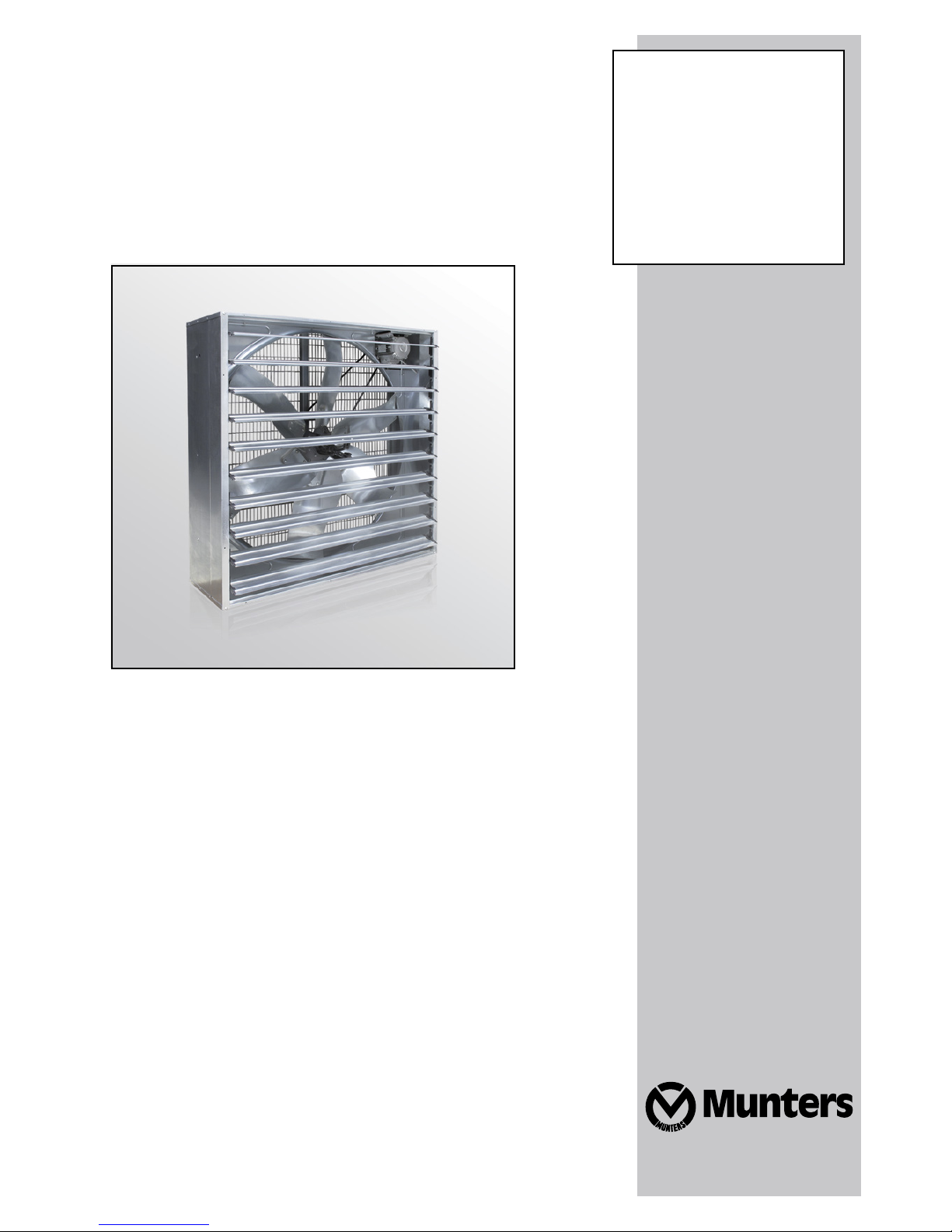
EM52
Exhaust fan
EM52
Ag/MIT/IGB-2207-09/14 rev 1.0
Page 2

© Munters AB, 2014
2
EM52
Assembly manual
Original instructions
This document is destined for the user of the apparatus: it may not be reproduced in whole or in part, committed
to computer memory as a file or delivered to third parties without the prior authorisation of the assembler of the
system.
Munters Italy S.p.A. reserves the right to effect modifications to the apparatus in accordance with technical and
legal developments.
Page 3

© Munters AB, 2014
3
Index
chapter page
1. SPARE PART LIST 4
EM52 exploded view 4
Spare parts 5
2. ASSEMBLING TOOLS 13
3. ASSEMBLING GUIDELINES 15
Housing assembling 15
Centrifugal system and pulley to propeller assembling 17
Shutter blades assembling 20
Motor assembling 21
CE Kit assembling 22
Optional pyramidal shape mesh assembling 23
All the components and spare parts MUST be storaged in dry and clean
environment.
WARNING
!
Page 4
© Munters AB, 2014
4
19
21
20
2223
12
25
27
28
9
6
8
38 37
36 29
30
33
35
31
17 18
1
2
5
3
15
39 26
11
10
7
13
52
32
16
50 51
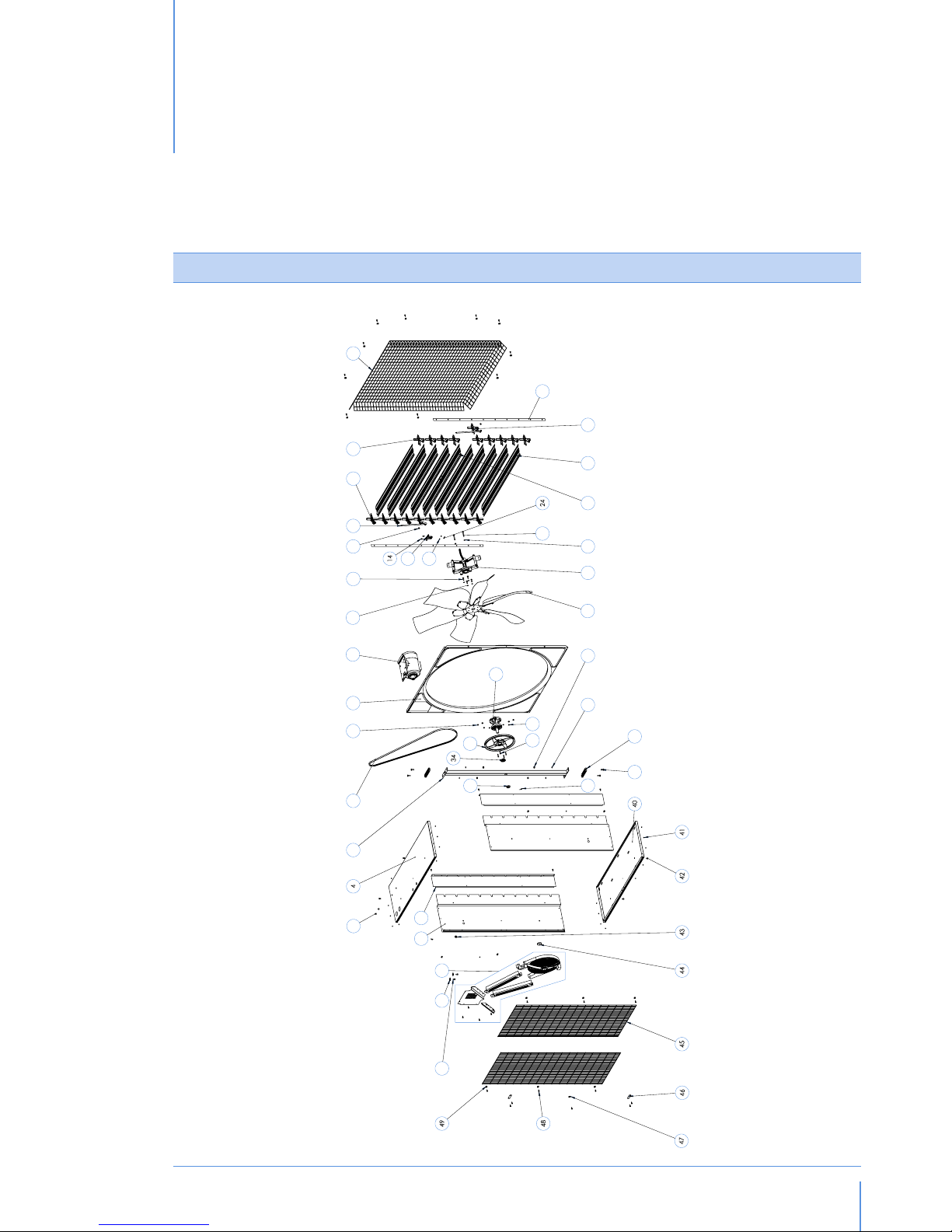
Spare part list
EM52
fig.1
Page 5
© Munters AB, 2014
5
Spare part listChapter1
Spare parts
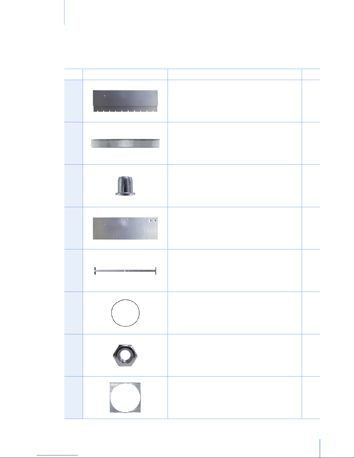
Ref. Picture Description Q.ty
1 SIDE PANEL 2
2 CARTER 2
3 THREADED BUSH M8X12.5 2
4 TOP PANEL 1
5 CENTRAL SUPPORT 1
6 V-BELT A90 1
7 HEXAGONAL NUT M8 6
8 CONVEYOR 1
Page 6
© Munters AB, 2014
6
Spare part listChapter1
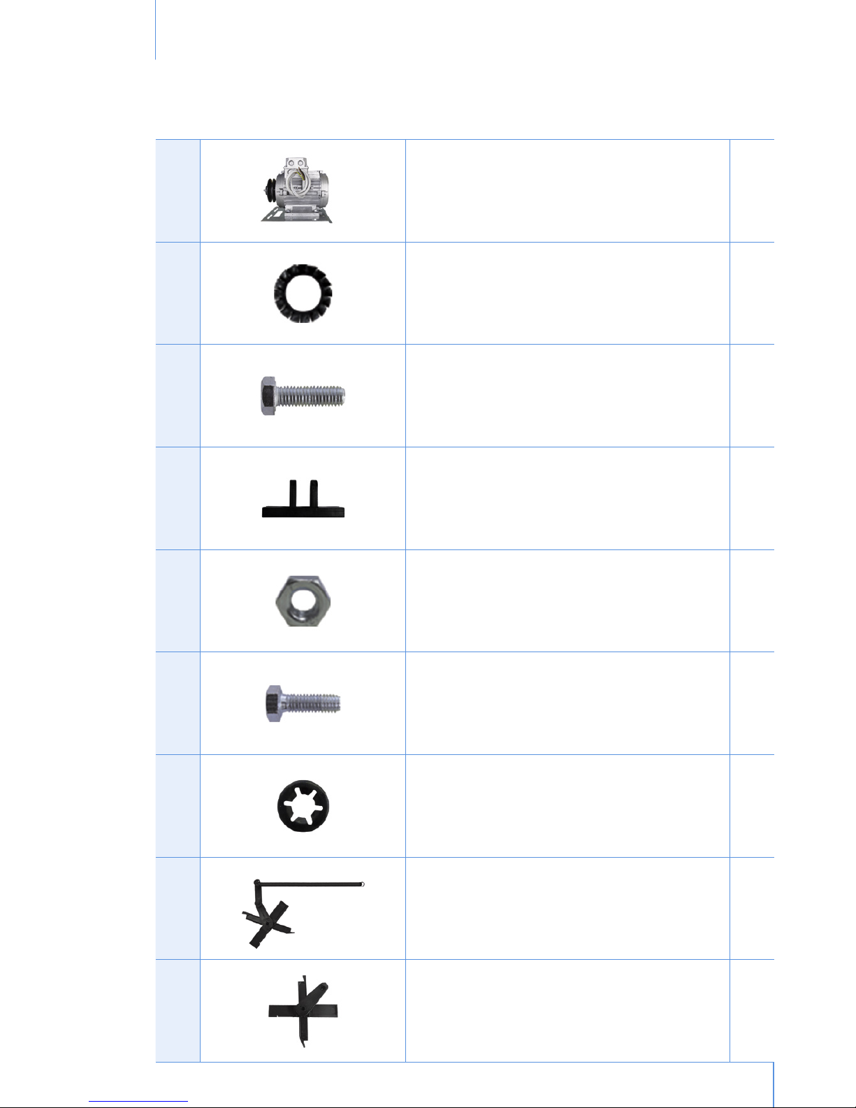
9 MOTOR 1
10 EXT TOOTHED WASHER D8 4
11 HEXAGON SCREW M8x25 4
12 PLASTIC FORK 1
13 HEXAGON NUT M6 THIN 2
14 HEXAGONAL SCREW M6X16 2
15 STOP COLLAR D7X17 2
16 CENTRAL RIGHT BEARING 1
17 RIGHT BEARING 9
Page 7
© Munters AB, 2014
7
Spare part listChapter1
18 LEFT BEARING 9
19 PYRAMIDAL REAR SAFETY MESH 1
20 TIE ROD 2
21 CENTRAL LEFT BEARING 1
22 SHUTTER BLADE 9
23 CENTRAL SHUTTER BLADE 1
24 KNURLED AXLE 1
25 HEXAGON SOCKET HEAD CUP SCREW M8X55 2
26 PLAIN WASHER D8,4X17 2
Page 8
© Munters AB, 2014
8
Spare part listChapter1
27 CENTRIFUGAL SYSTEM 1
28 PROPELLER 1
29 HEXAGONAL NUT M10 4
30 COMPLETE CENTRAL HUB 1
31 HEXAGONAL SCREW M6X30 4
32 HEXAGONAL NUT M6 WITH FLANGE 4
33 CENTRAL PULLEY 1
34 WATERPROOF DISTANCE PIECE 1
35 HEXAGONAL NUT M25 1
Page 9

© Munters AB, 2014
9
Spare part listChapter1
36 EXT TOOTHED WASHER D10,5X18 4
37 OVAL PLATE 2
38 HEXAGON SOCKET COUNTERSUNK SCREW M10X30 4
39 SPRING HOOK 2
40 BOTTOM PANEL 1
41 POP UP RIVET D4.8X7 20
42 THREADED BUSH D8X17.5 8
43 RUBBER GROMMET 1
44 CAP COVER NUT 1
Page 10

© Munters AB, 2014
10
Spare part listChapter1
45 REAR SAFETY MESH 2
46 METAL CLIP FOR MESHES 2
47 PLAIN WASHER D6X24 + SEALING 1
48 SELF TAPPING SCREW D6.3X19 25
49 PLASTIC CLIP FOR MESHES 16
50 HEXAGONAL SCREW M8X16 2
51 PLAIN WASHER D8X32 2
Page 11

© Munters AB, 2014
11
Spare part listChapter1
52
A
SAFETY PROTECTION FOR CENTRAL PULLEY (OPTIONAL) 1
B
SAFETY PROTECTION FOR MOTOR (OPTIONAL) 1
C
METAL CLIP FOR SAFETY PROTECTION FOR MOTOR (OPTIONAL) 1
D
SAFETY PROTECTION FOR V-BELT (OPTIONAL) 2
E
SELF TAPPING SCREW 6.3X19 (OPTIONAL) 4
53 EUROEMME STICKER 18X131 1
54 WARNING STICKER A-1997 35X210 2
55 WARNING STICKER B-1997 70X105 1
56 PRODUCT LABEL G-1998 95X115 1
Page 12

© Munters AB, 2014
12
Spare part listChapter1
57 NO HIGH PRESSURE STICKER 42X118 2
58 MUNTERS PROTECT STICKER 70X46 1
Page 13

© Munters AB, 2014
13
Assembling tools
2.
Ref. Picture Description Q.ty
1 RIVETING MACHINE RAC171 1
2 INSERTING MACHINE KJ 45 1
3 PNEUMATIC SCREWDRIVER 1
4 17mm SPANNER 1
5 10mm LONG SPANNER 1
6 13mm LONG SPANNER 1
7 6mm LONG ALLEN SPANNER 1
Page 14

© Munters AB, 2014
14
Assembling toolsChapter2
8 36mm SPANNER 1
9 PHILLIPS SCREW HEAD ADAPTOR 1
10 13mm RING SPANNER 1
11 SMALL HAMMER 1
12 10mm COMBINATION SPANNER 2
13 SCREWDRIVER 1
14 RATCHET DRIVE EXTENSION 1
15 17MM COMBINATION SPANNER 1
Page 15

© Munters AB, 2014
15
Assembling guidelines
3.
HOUSING ASSEMBLING
Take the bottom panel (ref. 40), the side panels (ref. 1)
and place these taking care that slot for the plastic
bearing is downward.
Before fixing the bottom and the side panels make
sure that these pieces are in the right position as in
the picture.
Join bottom panel to side panels and fix qty. 4 pop
rivets (ref. 41) for each edge by using riveting machine
(ref. 1/Assembling Tools).
Insert Venturi (ref. 8) into the housing on the right side
as in the picture.
Fix Venturi to bottom panel and then to side panels
with qty.1 pop rivets for side.
Page 16

© Munters AB, 2014
16
Assembling guidelinesChapter3
Place the top panel (ref. 4) with motor support in
correspondence with motor slot on the Venturi. Then
fix it to side panels with qty. 4 pop rivets for side and
to Venturi with qty.1 pop rivet.
Place the qty. 2 short threaded bushes (ref. 3) on
the top panel by using inserting machine (ref. 2/
Assembling Tools).
Place long threaded bushes (ref. 42) in correspondence
of proper holes around the housing. Qty. 2 long
threaded bushes for each panel.
Make sure that Venturi and each panel are joined by
the long threaded bushes.
Place the rubber grommet (ref. 43) for electric cable
protection on the side panel in correspondence with
the motor slot.
The propeller central support (ref. 5) shall be fixed to
housing by means of qty. 4 screws (ref. 30), qty. 2
oval plates (ref. 7), qty. 4 toothed washers (ref. 36)
and qty. 4 nuts (ref. 29).
Place the oval plates between propeller central
support and panels.
Page 17

© Munters AB, 2014
17
Assembling guidelinesChapter3
Place the oval plate over support frame and then start
to screw the nuts.
Tighten the nuts with pneumatic screwdriver (ref.3/
Assembling tools) in order to fix the propeller central
support to the top and bottom panels.
Insert the electric motor (ref. 9) into its slot taking care
to fix it over proper track on the top side.
Fix motor slide to top panel by means qty. 2 screws
(ref. 50) and qty. 2 washers (ref.51). Tighten screws
by using 13mm spanner (ref.10/Assembling tools).
CENTRIFUGAL SYSTEM AND PULLEY TO PROPELLER ASSEMBLING
Place the pulley on the hub (ref. 30) and insert the
screws (ref. 31).
Turn the pulley plus the hub upside down, insert the
nuts with flange (ref. 32) over the screws.
Page 18

© Munters AB, 2014
18
Assembling guidelinesChapter3
Tighten the nuts by using pneumatic screwdriver (ref.3/
Assembling tools).
Place the waterproof distance piece (ref. 34) on the
axle and then place the axle on a support. Place the
V-belt (ref. 6) on the central pulley.
Place the propeller (ref. 28) on the central pulley
assembly.
Fix the screws (ref. 11), washers (ref. 10) and nuts
(ref. 7) in order to fix the propeller.
Tighten the nuts by using pneumatic screwdriver
(ref. 3/Assembling tools).
Place screws (ref. 25) and plain washer (ref. 26) on
the centrifugal system (ref. 27) and then place it on
the propeller.
Page 19

© Munters AB, 2014
19
Assembling guidelinesChapter3
Tighten screws, washers and nuts (ref. 7) in order to
fix the centrifugal system to the propeller by using
pneumatic screwdriver (ref. 3/Assembling tools).
Place the complete assembly you have obtained on
the fan, inserting the axle throught the central support
hole.
Place the nut (ref. 35) on the axle and then tighten
it by mean of a 36mm spanner (ref. 8/Assembling
tools).
Put cap cover nut (ref. 44) over the nut (only for fan
without CE kit ).
Place V-belt (ref. 6) on the pulley and then rotate the
propeller clock-wise in order to tighten the V-belt on
the pulley.
Check tensioning: right tensioning is obtained when
maximum deflexion on one side only (half-way from
motor and central pulley) is about 15 mm.
Page 20

© Munters AB, 2014
20
Assembling guidelinesChapter3
SHUTTER BLADES ASSEMBLING
Insert plastic bearings (ref. 17/18) on shutter blades
(ref. 22) and plastic bearings with spring (ref. 16/21)
on central shutter blade (ref. 23). Both plastic bearings
are marked with SX for left side and with DX for right
side.
Fix the plastic fork with qty. 2 screws (ref. 14) and qty.
2 nuts (ref. 13) on the central shutter blade. Fit central
shutter blade on the central slot on the housing.
Insert knurled axle (ref. 24) by the smooth side on
the plastic fork, then take plastic shutter rod on the
centrifugal system and fix them together by using a
small hammer (ref. 11/Assembling tools).
Insert the spring hooks (ref. 39) in the holes of the side
panels (ref. 1).
Insert the free terminal of the spring on the hook.
Page 21

© Munters AB, 2014
21
Assembling guidelinesChapter3
Insert all the shutter blades on the fan housing and
then place the fan horizontally.
Place the pvc tie-rod (ref. 20) on plastic bearing pivots.
Insert stop collars (ref. 15) on central plastic pivots.
Put cover plate (ref. 2) over the plastic bearing
mechanism.
By means of a screwdriver (ref. 13/Assembling tools)
insert cover plate over the fan housing. Fix the cover
plate on each side by using the screws (ref. 48) with
pneumatic screwdriver (ref. 3/Assembling tools).
REAR SAFETY MESHES ASSEMBLING
Turn the fan upside down and insert the electric cable
into the proper hole placed on the side panel.
Page 22

© Munters AB, 2014
22
Assembling guidelinesChapter3
Put the qty. 2 safety meshes guard (ref. 45) on the inlet
side of the fan.
Fix the qty. 6 screws (ref. 48) and qty. 6 clips (ref. 49)
on the fan side (qty. 3 for each side are required).
Fix the screws with the central clips (ref. 46) in
correspondence of the propeller central support on
the top panel and the bottom panel.
Fix the screw with the washer (ref. 47) into the central
pulley axle. Fix all the components by using the
pneumatic screwdriver (ref. 3/Assembling tools).
CE KIT ASSEMBLING
Before assembling the safety meshes complete the CE
kit. Join the plastic safety protection for central pulley
(ref. 52/A) with plastic safety protection for the V-belt
(ref. 52/D).
Page 23

© Munters AB, 2014
23
Assembling guidelinesChapter3
Place the plastic safety protection for the motor pulley
(ref. 52/B) in the motor corner (make sure that the
metal square pins are inserted in the proper housing
holes). Join the metal safety protection for the motor
pulley.
Put the assembled CE plastic kit protection (make sure
that the groove of the plastic safety protection for the
V-belt are centered along the V-belt). Follow the safety
mesh guard assembling procedures and then fix the
complete assembled you have obtained by mean of
qty.1 screw (ref. 52/E).
Put the metal clip for safety protection (ref. 52/C) over
the 2 safety protection for V-belt.
Fix the metal clip for safety protection with qty. 1 selftapping screw (ref. 48).
PYRAMIDAL SHAPE MESH ASSEMBLING
Put the pyramidal shape mesh (ref. 19) on the fan as in
the picture. The rectangular holes must be positioned
horizontally.
Fix it to the bottom and top panels by means of qty. 10
plastic clips and qty. 10 screws (ref. 48). The plastic
clips must be fixed in the position as in the picture.
Page 24

© Munters AB, 2014
24
Assembling guidelinesChapter3
Fix it by using a pneumatic screwdriver (ref. 3/
Assembling tools).
Page 25

Euroemme® EM52 extraction fan is developed and produced by Munters Italy S.p.A., Italy
Euroemme
®
is a trademark of Munters AB
www.munters.com
Australia Munters Pty Limited, Phone +61 2 8843 1594, Brazil Munters Brasil Industria e Comercio Ltda, Phone +55 41 3317 5050, Canada Munters Corporation
Mason, Phone +1 517 676 7070, China Munters Air Treatment Equipment (Beijing) Co. Ltd, Phone +86 10 80 418 000, Denmark Munters A/S, Phone
+45 9862 3311, India Munters India, Phone +91 20 6681 8900, Indonesia Munters, Phone +62 818 739 235, Italy Munters Italy S.p.A., Chiusavecchia,
Phone +39 0183 52 11, Japan Munters K.K., Phone +81 3 5970 0021, Korea Munters Korea Co. Ltd., Phone +82 2 761 8701, Mexico Munters Mexico, Phone
+52 818 262 54 00, Russia Munters AB, Phone +7 812 448 5740, Singapore Munters Pte Ltd., Phone +65 744 6828, South Africa and Sub-Sahara Countries
Munters (Pty) Ltd., Phone +27 11 997 2000, Spain Munters Spain S.A., Phone +34 91 640 09 02, Sweden Munters AB, Phone +46 8 626 63 00, Thailand
Munters Co. Ltd., Phone +66 2 642 2670, Turkey Munters Form Endüstri Sistemleri A.Ş, Phone +90 262 751 3750, USA Munters Corporation Mason, Phone
+1 517 676 7070, Vietnam Munters Vietnam, Phone +84 8 3825 6838, Export & Other countries Munters Italy S.p.A., Chiusavecchia Phone +39 0183 52 11
© Munters AB, 2014
Ag/MIT/IGB-2207-09/14 rev 1.0
 Loading...