

Page 1
Assembly manual
Spare part list + Assembling guideline
EC52
Exhaust fan
EC52
Ag/MIT/IGB-2206-08/14 rev 1.0
Page 2

© Munters AB, 2014
2
EC52
Assembly manual
Original instructions
This document is destined for the user of the apparatus: it may not be reproduced in whole or in part, committed
to computer memory as a file or delivered to third parties without the prior authorisation of the assembler of the
system.
Munters Italy S.p.A. reserves the right to effect modifications to the apparatus in accordance with technical and
legal developments.
Page 3

© Munters AB, 2014
3
Index
chapter page
1. SPARE PART LIST 4
EC52 exploded view 4
Spare parts 6
2. ASSEMBLING TOOLS 16
3. ASSEMBLING GUIDELINES 19
Housing assembling 19
Centrifugal system and pulley to propeller assembling 21
Propeller and motor to central support assembling 22
Shutter blades assembling 28
Cone discharge assembling 31
Optional belt tensioner assembling 33
Optional pyramidal shape mesh assembling 35
All the components and spare parts MUST be storaged in dry and clean
environment.
WARNING
!
Page 4
© Munters AB, 2014
4
A
B
C
D
1
6
5
10
14
7
12
11
15
19
21
17
4
20
22
23
24
26
3
18
2
9
16
17
3131
13
8
25
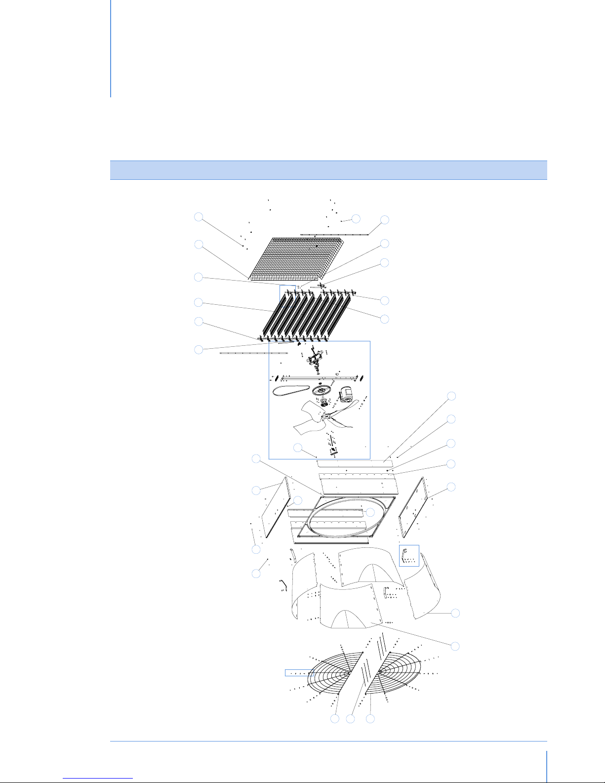
A
Spare part list
EC52
fig.1
Page 5

© Munters AB, 2014
5
57
56
46 60
58
59
60
55
66
65
67
64
6362
38
48
52
553848 54 53
55
38
48
54
53
40
37
3938
50
434942 44
47
38
46
32
33
34
35
41
36
51
61
45
48
3938
68
27
28
8
30
31
28
8
29
27
DETAIL A
fig.2
DETAIL B
fig.3
DETAIL C
fig.4
Spare part listChapter1
Page 6

© Munters AB, 2014
6
DETAIL D: ALIGNEMENT OF SHUTTER BLADE
fig.5
POSITIONING OF REINFORCEMENT
fig.6
ALIGNEMENT OF BELLEVILLE SPRING
fig.7
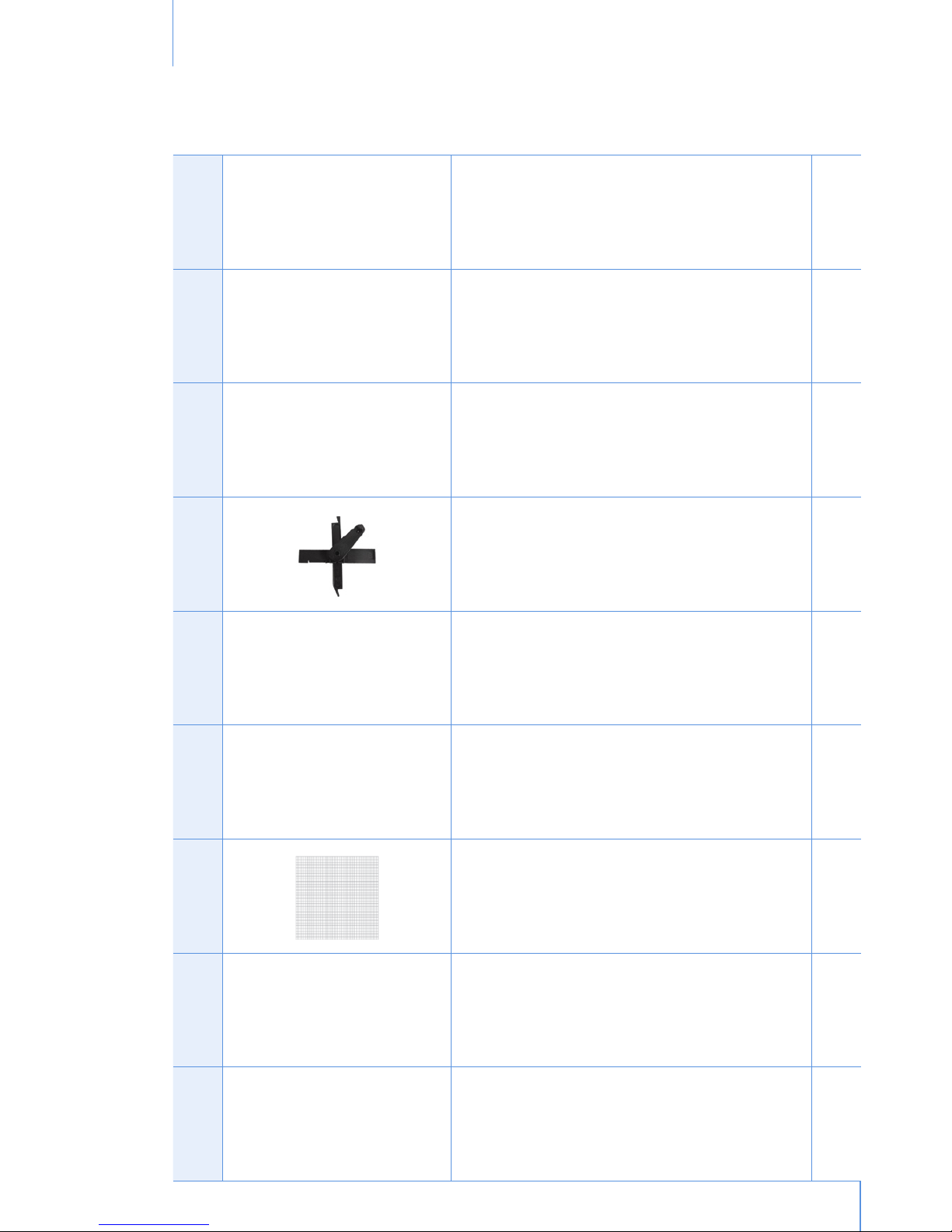
Spare parts
Ref. Picture Description Q.ty
1 THREADED BUSH M8X12.5 8
2 POP UP RIVET 4.9X7 STEEL 26
Spare part listChapter1
Hex socket screw M8
with spring washer D8 to
fix reinforcement
Page 7
© Munters AB, 2014
7
3 TOP PANEL 1
4 CONVEYOR 1
5 CENTRAL RIGHT PLASTIC BEARING 1
6 RIGHT PLASTIC BEARING 9
7 SHUTTER BLADE 9
8 HEXAGON SCREW M6X16 28
9 PYRAMIDAL REAR SAFETY MESH 1
10 PLASTIC CLIP FOR MESH 10
11 STOP COLLAR D7X17 2
Spare part listChapter1
Page 8

© Munters AB, 2014
8
12 TIE ROD 2
13 HEXAGON NUT M6 2
14 CENTRAL LEFT PLASTIC BEARING 1
15 LEFT PLASTIC BEARING 9
16 CENTRAL SHUTTER BLADE 1
17 COVER PLATE 2
18 SPRING HOOK 2
19 RUBBER GROMMET 1
20 SIDE PANEL 2
Spare part listChapter1
Page 9

© Munters AB, 2014
9
21 BOTTOM PANEL 1
22 CONE SECTOR 2
23 CONE SECTOR CUT 2
24 CONE MESH INTERRUPTED WIRE 1
25 PLASTIC TIE LEGRAND MM9X357 6
26 CONE MESH CONTINUOUS WIRE 1
27 HEXAGON NUT THICK M6 26
28 PLAIN WASHER Ø6.4X24 44
29 SPRING WASHER D6 8
Spare part listChapter1
Page 10

© Munters AB, 2014
10
30 CONE BRACKETS 4
31 SELF TAPPING SCREW 6.3X19 22
32 HEXAGON SOCKET COUNTERSUNK HEAD SCREW M10X30 4
33 OVAL PLATE 2
34 CENTRAL SUPPORT 1
35 EXTERNAL TOOTHED WASHER D10 4
36 HEXAGON NUT M10 4
37 PLAIN WASHER D8X16 2
38 SPRING WASHER D8 8
Spare part listChapter1
Page 11

© Munters AB, 2014
11
39 HEXAGON SOCKET HEAD CAP SCREW M8X35 4
40 PLASTIC FORK 1
41 BRASS PIN 1
42 HEXAGON NUT M25 1
43 SPACER WASHER D25.2X29.5 1
44 REAR FLANGE 1
45 CENTRIFUGAL SYSTEM 1
46 HEXAGON SCREW M8X20 2
47 WASHER D8.2X27.8 THK 3.0MM 1
Spare part listChapter1
Page 12

© Munters AB, 2014
12
Spare part listChapter1
48 PLAIN WASHER D8X32 5
49 BEARING 16005-2RS 1
50 BELLEVILLE SPRING 1
51 HEXAGONAL NUT M8 WITH FLANGE 1
52 BELT TENSIONING ADJUSTER 1
53 HEXAGON SCREW M8X65 3
54 PLAIN WASHER D8X24 2
55 HEXAGONAL NUT M8 8
56 MOTOR 1
Page 13

© Munters AB, 2014
13
Spare part listChapter1
57 PROPELLER* 1
58 FLANGE FOR PROPELLER 1
59 HEXAGON SCREW M8X30 4
60 EXTERNAL TOOTHED WASHER D8 5
61 HEXAGONAL AXLE WITH M8 HOLES 1
62 HUB 1
63 HEXAGONAL NUT M6 WITH FLANGE 4
64 HEXAGON SCREW M6X30 4
65 CENTRAL PULLEY 1
Page 14

© Munters AB, 2014
14
66 V-BELT A61 1
67 WATERPROOF DISTANCE PIECE 1
68 FRONT FLANGE REINFORCEMENT 1
69 EUROEMME STICKER 24.6X180 2
70 WARNING STICKER A-1997 35X210 2
71 WARNING STICKER B-1997 70X105 1
72 PRODUCT LABEL G-1998 95X115 1
73 NO HIGH PRESSURE STICKER 42X118 2
74 MUNTERS PROTECT STICKER 70X46 1
Spare part listChapter1
Page 15

© Munters AB, 2014
15
75 TENSIONER (OPTIONAL) 1
76 METAL SPACER FOR BELT TENSIONER (OPTIONAL) 1
77 ALUMINUM POP UP RIVET 3.9X7(OPTIONAL) 2
78 HEXAGON SCREW M10X90 (OPTIONAL) 1
79 EXTERNAL TOOTHED WASHER 10.5×18 (OPTIONAL) 1
80 PLAIN WASHER 10.5×40 (OPTIONAL) 1
Spare part listChapter1
Page 16

© Munters AB, 2014
16
Ref. Picture Description Q.ty
1 RIVETING MACHINE RAC171 1
2 INSERTING MACHINE KJ 45 1
3 PNEUMATIC SCREWDRIVER 1
4 17mm SPANNER 1
5 10mm LONG SPANNER 1
6 13mm LONG SPANNER 1
7 6mm LONG ALLEN SPANNER 1
Assembling tools
2.
Page 17

© Munters AB, 2014
17
8 36mm SPANNER 1
9 PHILLIPS SCREW HEAD ADAPTOR 1
10 13mm RING SPANNER 1
11 SMALL HAMMER 1
12 10mm COMBINATION SPANNER 2
13 SCREWDRIVER 1
14 RATCHET DRIVE EXTENSION 1
15 17MM COMBINATION SPANNER 1
Assembling toolsChapter2
Page 18

© Munters AB, 2014
18
16 10MM ALLEN KEY 1
Assembling toolsChapter2
Page 19

© Munters AB, 2014
19
Assembling guidelines
3.
HOUSING ASSEMBLING
Take the bottom panel (ref. 21), the side panels (ref.
22) and place them taking care that slot for the plastic
bearing is downward.
Before fixing the bottom and the side panels make
sure that these pieces are in the right position as in the
picture (place the edge of the bottom panel outside
the side panel).
Join bottom panel with side panels and fix qty. 3 pop
rivets (ref. 2) for each edge by using riveting machine
(ref. 1/Assembling tools). To make the mounting of
the Venturi (ref. 4) easy take care to fix the signed
pop rivet after the Venturi assembling (see arrow in the
previous picture).
Insert Venturi into the housing on the right side as in
the picture. Fix Venturi to bottom panel and then to
side panels with qty. 3 pop rivets for side. Fix the last
pop rivets of the previous step. Qty. 1 pop rivet for
each edge.
Place the top panel (ref. 3) as in the picture (place the
edge of the bottom panel outside the side panel).
Page 20

© Munters AB, 2014
20
Fix it to side panels with qty. 4 pop rivets for side: qty.
3 lateral + qty. 1 frontal.
Fix it to Venturi with qty. 3 pop rivets.
Place the threaded bushes (ref. 1) in correspondence
of proper holes around the housing. Qty. 2 threaded
bushes for each panel.
The propeller central support (ref. 34) shall be fixed
to housing by means of qty. 4 bolts (ref. 32, qty. 4
washers (ref. 35), qty. 4 nuts (ref. 36) and qty. 2 oval
plates (ref. 33). The holes for motor slide and optional
belt tensioner have to be on lower side of the fan (near
to bottom panel).
Place the oval plates between propeller central support
and panels. The conic surface of the holes shall face
the metal panels (top and bottom).
Assembling guidelinesChapter3
Page 21

© Munters AB, 2014
21
Place the oval plates over support frame and then start
to screw the nuts. Tighten it by using pneumatic screwdriver (ref. 3/Assembling tools).
CENTRIFUGAL SYSTEM AND PULLEY TO PROPELLER ASSEMBLING
Take the pulley (ref. 65) and insert qty. 4 M6x30
screws (ref. 64) on external part of it.
Turn the pulley upside down and place the hub
(ref. 62) on it.
Insert and fix qty. 4 nuts with flange (ref. 63) over the
bolts.
Tighten the nuts by using pneumatic screw-driver (ref.
3/Assembling tools).
Place the waterproof distance piece (ref. 67) on the
axle and then place the axle on a support.
Assembling guidelinesChapter3
Page 22

© Munters AB, 2014
22
Assembling guidelinesChapter3
Place the v-belt (ref. 66) on the central pulley.
Before assembling the propeller make sure that the hub
is oriented as shown in the picture. The 4 highlighted
holes are used to fix the propeller to the hub.
Place the propeller (ref. 57) on the hub as shown in
pictures. Make sure that the holes with the pop rivets
are correctly oriented. The 4 highlighted holes are
used to fix the propeller to the hub.
Fix qty. 4 screws M8x30 (ref. 59), qty. 4 external
toothed washers (ref. 60) and qty. 4 M8 nuts (ref.
55) in order to fix the propeller.
Tighten the nuts by using pneumatic screw-driver (ref.
3/Assembling tools).
PROPELLER AND MOTOR TO CENTRAL SUPPORT ASSEMBLING
Place the propeller on the fan, by inserting the axle
through the central support hole.
Page 23

© Munters AB, 2014
23
Insert the belleville spring
(ref. 50) on the propeller
axle. Pay attention to
place it with its concave
side facing the central
support (see picture).
Insert the spacer washer D25.2x29.5 (ref. 43).
Insert the bearing (ref. 49).
Insert the M25 nut (ref. 42).
Tighten the nut by using a pneumatic screw-driver (ref.
3/Assembling tools) equipped with a 36 mm spanner
(ref. 8/Assembling tools) by applying a torque of
60Nm .
Put qty. 1 D8x32 plain washer (ref. 48) on back side
of the rear flange (ref. 44).
Assembling guidelinesChapter3
Page 24

© Munters AB, 2014
24
Insert the rear flange (ref. 44) into the centrifugal
system base (ref. 45).
Insert qty. 2 M8x35 screws (ref. 39), qty. 2 D8 spring
washers (ref. 38) and qty. 2 D8x16 plain washers
(ref. 37) to fix the centrifugal system to the rear flange.
Tighten them by means of a 6mm long allen spanner
(ref. 7/Assembling tools), closing torque 20Nm.
Place qty. 1 D8,2x27,8 washer (ref. 47) inside the
hole on the centrifugal system base (ref. 45).
Insert the hexagonal axle (ref. 61) on the bottom
side of the assembly. If necessary, push it hardly until
it touches the D8x32 plain washer (ref. 48), already
placed on the back side of the rear flange (ref. 44).
Fix the hexagonal axle (ref. 61) by using qty. 1
M8x20 screw (ref. 46), qty. 1 D8 spring washer (ref.
38) and qty. 1 D8x32 washer (ref. 48).
Assembling guidelinesChapter3
Page 25

© Munters AB, 2014
25
Tighten them by means of a 13mm ring spanner (ref.
10/Assembling tools).
On the front side of propeller mount the flange for
propeller (ref. 58) inserting its pins on the proper hole
of the propeller.
Put in position the front flange reinforcement (ref. 68).
Fix it by means of qty. 2 M8x35 screws (ref. 39) and
qty. 2 D8 spring washers (ref. 38).
Tighten them by means of a 6mm long allen spanner
(ref. 7/Assembling tools).
Insert the complete assembly on rear side of the central
pulley (ref. 65).
Assembling guidelinesChapter3
Page 26

© Munters AB, 2014
26
Insert a qty. 1 M8x20 screw (ref. 46) and qty. 1 D8
external toothed washer (ref. 60) and screw it on
thread present on hexagonal axle.
Tighten them by means of a 13mm ring spanner (ref.
10/Assembling tools).
Turn the fan and place the central support in horizontal
position. Place the assembled motor (ref. 56) on the
central support.
Fix motor slide on central support by qty. 2 M8×65
screws (ref. 53) and qty. 2 D8×24 washers (ref. 54)
as shown in the picture.
Insert qty. 2 D8×32 washers (ref. 48), qty. 2 D8
spring washers (ref. 38) and qty. 2 M8 nuts (ref. 55).
Screw the bolts without tightening.
Assembling guidelinesChapter3
Page 27

© Munters AB, 2014
27
Place the D8 spring washer (ref. 38) and the D8x32
plain washer (ref. 48) onto the M8x65 screw (ref.
53). Insert it in the proper hole* of the support and
tight it through the belt tensioning adjuster (ref. 52) by
using qty. 1 M8 nut with flange (ref. 51).
Please note that the round part of the belt tensioning
adjuster has to be oriented towards the propeller, as
shown in the pictures.
*NOTE: for M80 Motor/Hp1 use the hole nearest
to the central pulley (no. 1 in the picture); for M90
Frame Motor/Hp1.5 use the hole furthest from the
central pulley (no. 2 in the picture).
Bring motor in the nearest position toward central
pulley.
Put the v-belt on both central and motor pulley.
Assembling guidelinesChapter3
2
1
Page 28

© Munters AB, 2014
28
Give proper tension to v-belt by using a 10mm allen
key (ref. 16/Assembling tools).
CHECK TENSIONING: right tensioning is obtained
when maximum deflexion on one side only (half-way
from motor and central pulley) is about 10 mm.
TENSIONING VALUES:
Hp1 = 250 N, corresponding to a vibration frequency
55 Hz +/- 2%
Hp2 = 320 N, corresponding to a vibration frequency
60 Hz +/- 2%
NOTE: in case of installation of belt tensioner (optional)
please refer to ‘Optional belt tensioner assembling’
chapter (see p. 34).
Fix motor slide in its proper position by tightening the
motor slide screws by using two 13 mm spanners (ref.
10/Assembling tools).
Place the rubber grommet (ref. 19) on the left side
panel for electric cable protection.
SHUTTER BLADES ASSEMBLING
Insert the plastic bearings (ref. 6 and ref. 15) without
spring on all thin shutter blades (thickness 0.6 mm
- ref. 7). Plastic bearings marked with “DX” are for
right side, the ones marked with “SX” are for left side
(seeing the fan from its rear side). Be sure to assemble
the bearings with the right orientation (see picture).
Insert qty. 2 M6 nuts (ref. 13) in the slots of the plastic
fork (ref. 40) as shown in the picture.
Assembling guidelinesChapter3
Page 29

© Munters AB, 2014
29
Assemble the plastic fork (ref. 40) and the central
shutter blade (thickness 1.2 mm - ref. 16) with qty.
2 M6×16 screws (ref. 8) by using two 10 mm
combination spanners (ref. 12/Assembling tools).
Insert the plastic bearing with spring (ref. 5 and 14)
on the central shutter blade (ref. 17). “DX” is for right
side, “SX” is for left side.
Fit the assembled central shutter blade on the central
slot (fifth position from the top) of the housing.
Insert the spring hooks (ref. 18) in the holes of the side
panels (ref. 20).
Insert the free terminal of the spring on the hook.
Connect the centrifugal system to the fork of the central
shutter blade with the knurled brass pin (ref. 41). To
insert the pin use a small hammer (ref. 11/Assembling
tools).
Assembling guidelinesChapter3
Page 30

© Munters AB, 2014
30
Insert qty. 9 shutter blades (ref. 7) in the free slots of
the housing and then place the fan horizontally.
Fix the pvc tie-rod (ref. 12) on plastic bearing pivots.
The tie-rod must be fixed on the central plastic berings
(the ones with the spring) by using a stop collar (ref.
11).
Put the cover plates (ref. 17) over the plastic bearing
mechanism.
By means of a screw-driver (ref. 13/Assembling tools)
insert the cover plate over the fan housing.
Fix the cover plate on each side by using the 6.3×19
screws (ref. 31) with a pneumatic screw-driver (ref. 3/
Assembling tools).
Assembling guidelinesChapter3
Page 31

© Munters AB, 2014
31
CONE DISCHARGE ASSEMBLING
Assemble the cone sectors (ref. 22 and 23) as shown
in the pictures, inserting the wings of the first sector in
the slots of the second one. Repeat the operation for
all four sectors.
To obtain the discharge cone join the first sector with
the last one.
Make sure that the sectors wings are correctly inserted
in the slots and that the holes of the sectors are
coincident (see arrows).
Place the half mesh (ref. 24 or 26) on the discharge
cone. In order to fix it, use qty. 1 M6×16 screw (ref. 8)
with qty. 1 D6.4×24 washer (ref. 28) for the internal
side and qty. 1 D6.4×24 washer (ref. 28) with qty.
1 M6 nut (ref. 27) for the external side of the cone.
Repeat the operation for each of the seven spokes of
the half mesh.
Tighten the screws by using two 10 mm combination
spanners (ref. 12/Assembling tools) or similar 10mm
tool.
Assembling guidelinesChapter3
Page 32

© Munters AB, 2014
32
Complete the assemblage of the cone sectors by using
qty. 1 M6×16 screw (ref. 8) with qty. 1 D6.4×24
washer (ref. 28) for the internal side and qty. 1
D6×24 washer (ref. 28) with qty. 1 M6 nut (ref. 27)
for the external side of the cone, as previosly done.
Repeat the operation for each of the four sectors of
the discharge cone.
Tighten the screws by using two 10 mm spanners (ref.
12/Assembling tools).
Assemble the remaining half mesh in the same way.
Fix the cone bracket (ref. 30) to the discharge cone
by using qty. 1 M6×16 screw (ref. 8) with qty. 1
D6.4×24 washer (ref. 28) for the internal side and
qty. 1 D6 spring washer (ref. 29) with qty. 1 M6 nut
(ref. 27) for the external side of the cone.
Make sure that the bracket is assembled in the correct
way, as shown in the picture, and tighten the screw
with two 10 mm combination spanners (ref. 12/
Assembling tools). Repeat the operation for each of
the four brackets of the discharge cone.
Place the complete assembly on the conveyor.
Make sure that the discharge cone is positioned
outside of the conveyor edge.
Assembling guidelinesChapter3
Page 33

© Munters AB, 2014
33
Assembling guidelinesChapter3
Fix the discharge cone to the conveyor with q.ty. 8
D6.3×19 screws (ref. 31) by using a pneumatic
screw-driver (ref. 3/Assembling tools) and its proper
adapter (ref. 9/Assembling tools).
Join together the half meshes by tightrning the plastic
ties as shown in the pictures.
Joint firmly the 2 meshes together by means of the 6
plastic ties (ref. 25) supplied.
OPTIONAL BELT TENSIONER ASSEMBLING
Insert the pop up rivet 3.9x7 (ref. 77) in the metal
spacer by using a pneumatic screw-driver (ref. 3/
Assembling tools).
Place the metal spacer on the tensioner (ref. 76),
making sure to insert the pins of the spacer in the slots
of the tensioner.
Page 34

© Munters AB, 2014
34
2
1
Insert the D10.5 toothed washer (ref. 79) and the
D10.5 plain washer (ref. 80) in the M10×90 screw
(ref. 78) and fix the tensioner to the central support
by means of a 17mm combination spanner (ref. 3/
Assembling tools).
Place the D8 spring washer (ref. 38) and the D8x32
plain washer (ref. 48) onto the M8x65 screw (ref.
53). Insert it in the proper hole* of the support and
tight it through the belt tensioning adjuster (ref. 52) by
using qty. 1 M8 nut with flange (ref. 51).
Please note that the round part of the belt tensioning
adjuster has to be oriented towards the propeller, as
shown in the pictures.
*NOTE: for M80 Motor/Hp1 use the hole nearest
to the central pulley (no. 1 in the picture); for M90
Frame Motor/Hp1.5 use the hole furthest from the
central pulley (no. 2 in the picture).
Place the V-belt on the pulleys.
Assembling guidelinesChapter3
Page 35

© Munters AB, 2014
35
Assembling guidelinesChapter3
Tighten with a 10 mm allen key (ref. 16/Assembling
tools).
TENSIONING VALUES:
Hp1 = 250 N, corresponding to a vibration frequency
55 Hz +/- 2%
Hp2 = 320 N, corresponding to a vibration frequency
60 Hz +/- 2%
Check the final position of the tensioner. If the tensioner
looks like the picture (mark on the 2nd slot) it will be in
the right position.
Otherwise repeat this step by changing motor position.
OPTIONAL PYRAMIDAL SHAPE MESH ASSEMBLING
Put the pyramidal shape mesh (ref. 9) on the fan like
the picture. The rectangular holes must have the long
side in horizontal position.
Fix it to the bottom and top panels by means of qty.
10 plastic clips (ref. 10) and qty. 10 D6.3x19 screws
(ref. 31).
The clips must be fixed in the same position as shown
in the picture.
Fix it by using a pneumatic screwdriver (ref. 3/
Assembling tools) and its proper adapter (ref. 9/
Assembling tools).
Page 36

Euroemme® EC52 extraction fan is developed and produced by Munters Italy S.p.A., Italy
Euroemme
®
is a trademark of Munters AB
www.munters.com
Australia Munters Pty Limited, Phone +61 2 8843 1594, Brazil Munters Brasil Industria e Comercio Ltda, Phone +55 41 3317 5050, Canada Munters Corporation
Mason, Phone +1 517 676 7070, China Munters Air Treatment Equipment (Beijing) Co. Ltd, Phone +86 10 80 418 000, Denmark Munters A/S, Phone
+45 9862 3311, India Munters India, Phone +91 20 6681 8900, Indonesia Munters, Phone +62 818 739 235, Italy Munters Italy S.p.A., Chiusavecchia,
Phone +39 0183 52 11, Japan Munters K.K., Phone +81 3 5970 0021, Korea Munters Korea Co. Ltd., Phone +82 2 761 8701, Mexico Munters Mexico, Phone
+52 818 262 54 00, Russia Munters AB, Phone +7 812 448 5740, Singapore Munters Pte Ltd., Phone +65 744 6828, South Africa and Sub-Sahara Countries
Munters (Pty) Ltd., Phone +27 11 997 2000, Spain Munters Spain S.A., Phone +34 91 640 09 02, Sweden Munters AB, Phone +46 8 626 63 00, Thailand
Munters Co. Ltd., Phone +66 2 642 2670, Turkey Munters Form Endüstri Sistemleri A.Ş, Phone +90 262 751 3750, USA Munters Corporation Mason, Phone
+1 517 676 7070, Vietnam Munters Vietnam, Phone +84 8 3825 6838, Export & Other countries Munters Italy S.p.A., Chiusavecchia Phone +39 0183 52 11
© Munters AB, 2014
Ag/MIT/IGB-2206-08/14 rev 1.0
 Loading...