

Page 1
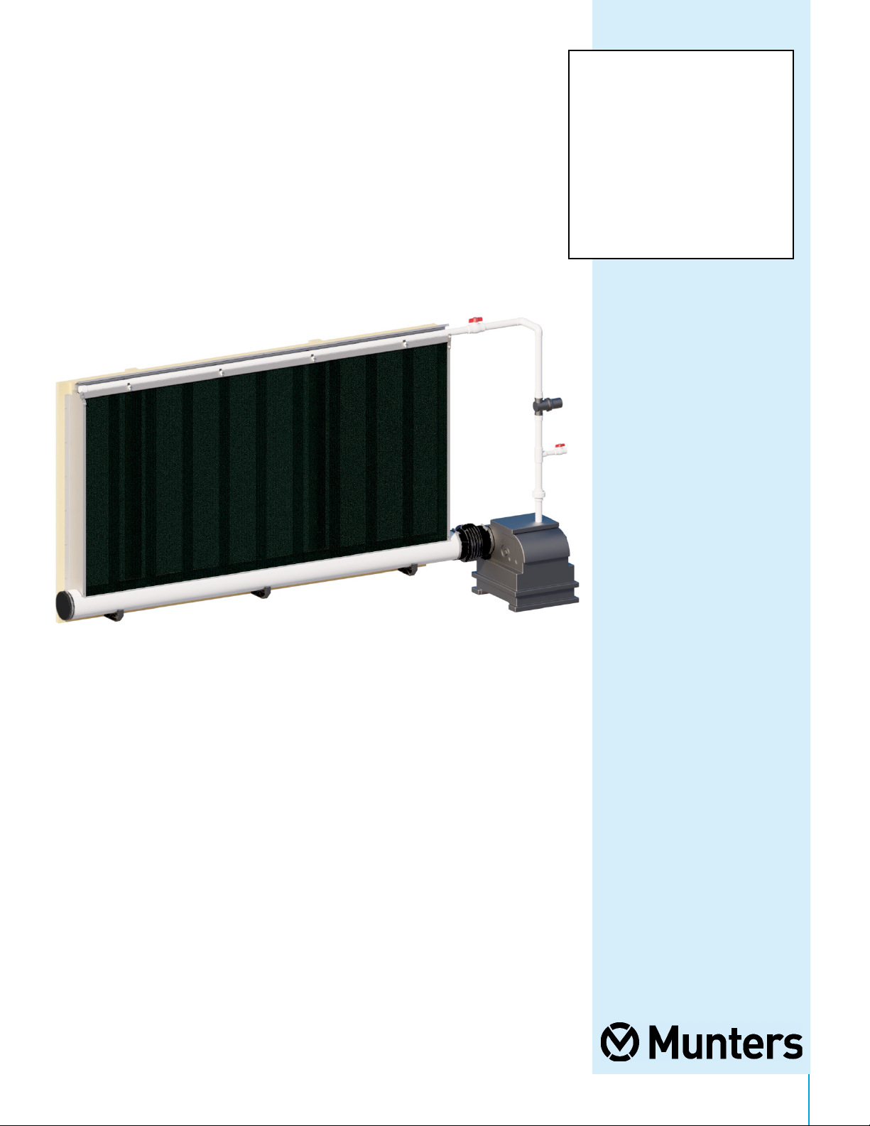
Instruction Manual
CB
Evaporative
Cooling System
with End Tank
EC1682
CB Evaporative Cooling System
with End Tank
Models: CB10 with EC1682
QM1138r4
1© Munters Corporation, May 2021
Page 2

CB Evaporative Cooling System with End Tank
Instructions for Use and Maintenance
Thank You:
Thank you for purchasing a Munters CB Evaporative Cooling System. Munters equipment is designed to be the
highest performing, highest quality equipment you can buy. With the proper installation and maintenance it will
provide many years of service.
Please Note:
To achieve maximum performance and insure long life from your Munters product it is essential that it be
installed and maintained properly. Please read all instructions carefully before beginning installation.
Warranty:
For Warranty claims information see the “Warranty Claims and Return Policy” form QM1021 available from the
Munters Corporation office at 1-800-227-2376 or by e-mail at aghort.info@munters.com.
Conditions and Limitations:
• Products and Systems involved in a warranty claim under the “Warranty Claims and Return Policy” shall have
been properly installed, maintained and operated under competent supervision, according to the instructions
provided by Munters Corporation.
• Malfunction or failure resulting from misuse, abuse, negligence, alteration, accident or lack of proper
installation or maintenance shall not be considered a defect under the Warranty.
2
QM1138r4
© Munters Corporation, May 2021
Page 3

Index
Chapters Page
1. Unpacking the Equipment 4
2. Installation Instructions 6
3. Plumbing Installation 16
3.2 Float Valve 19
4. Operation 22
4.2 System Operation and Adjustment 22
1.1 Parts List 4
1.2 Dimensions 5
2.1 Installation 6
3.1 Black Poly Tank 16
3.3 Optional Flush-out Kit (EC1507) 21
3.4 Plumbing Layout with Submersible Pump 21
4.1 System Start-up 22
5. Maintenance 23
5.1 Minimum Maintenance Schedule 23
5.2 Maintenance Checklist 23
6. Exploded View and Parts List 24-25
QM1138r4
3© Munters Corporation, May 2021
Page 4
Unpacking the Equipment
1.
Before beginning installation, check the overall condition of the equipment. Remove packing materials, and examine all
components for signs of shipping damage. Any shipping damage is the customer’s responsibility and should be reported
immediately to your freight carrier. CB Evaporative Cooling System is shipped with all parts and accessories in one crate.
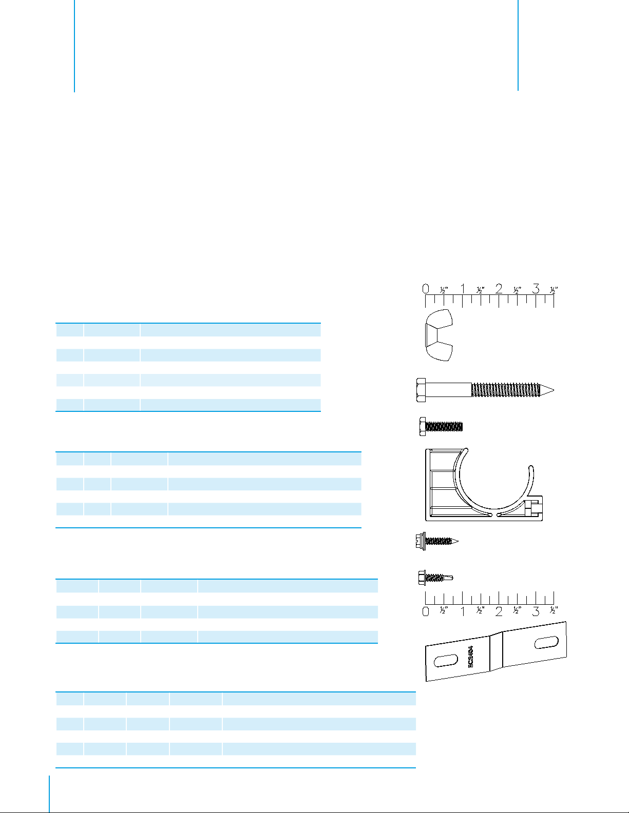
1.1 Parts List
Munters CB Evaporative Cooling Systems are are configured in 10'L. modules or a bulk option of 480'L. giving you the
option of a single house or an entire site. Each system requires an Ending Kit, Tank Kit and Pump, each ordered separately.
CB Cooling System Legths up to 80'L. requires 1 Tank and Pump. Systems longer than 80'L. require 2 Tanks and Pumps.
For a 5'H. system order EC4405 Ending Kit, for a 6'H. system order EC4406 Ending Kit.
A 60'L. x 6'H. system would consist of (6) CB10, (1) EC4406 Ending Kit, (1) EC1682 End Tank Kit and (1) Pump.
A four house site with (2) 80'L. x 5'H. would consist of (1) CB480, (16) CB10, (8) EC4405 Ending Kits, (8) EC1682 Tank
Kits and (8) Pumps.
Each CB10 System Includes:
Qty. Cat. No. Description
1 JP3028 8" Pipe with Cut Lines, PVC
1 EC2402 Drip Collector, 10'L., SS
1 EC2400 Distribution Cap, 10'L., SS
1 EC2401 Pad Retainer, 10'L., SS
2 EC2413 Pipe Support Bracket, PL
1 EC1498 Pipe, 1.5"Dia. x 10'-2¹⁄₂"L., with Holes, PVC
1 HP1610 Hardware Package, CB10 Cooling Module
[A]
[B]
Hardware Package (HP1610) for CB10
ID Qty Cat. No. Description
[A] 7 KN23011⁄4”-20 Wing Nut, Type-A, NY, Natural Color
[B] 4 KS24623⁄8” x 3¹⁄₂” Lag Screw, HOT DIP GALV.
[C] 7 KS10191⁄4”-20 x 1” Hex Bolt, SS
[D] 4 EC2410 Pipe Holder, 1.5"Pipe, PL
[E] 18 KS1404 #10-14 x 1” Seal Washer Polebarn Screw, ZP
[F] 1 KS2282 #10-16 x ³⁄₄” HXWSR TEK Screw, SS
Each EC4405/EC4406 Ending Kit Includes:
EC4405
Qty.
Hardware Package (HP1705/HP1706) for EC4405/EC4406
ID
[A] 4 8 KN23011⁄4”-20 Wing Nut, Type-A, NY, Natural Color
[B] 2 2 KS2462
[C] 4 8 KS10191⁄4”-20 x 1” Hex Bolt, SS
[E] 8 12 KS1404 #10-14 x 1” Seal Washer Polebarn Screw, ZP
[F] 2 2 KS2282 #10-16 x ³⁄₄” HXWSR TEK Screw, SS
[G] 2 2 EC2404 End Panel Retainer Bracket, SS
EC4406
Qty. Cat. No. Description
2 2 EC1400 End Panel for 5'H. System, SS
--- 2 EC1412 End Panel Extension, 1'H., CB Cooling, SS
2 2 EC1359 1.5"Dia. x 59.5"L. Pipe Nipple, PVC
1 1 EC2413 Pipe Support Bracket, PL
1 1 HP1705/6 Hardware Package, Ending Kit, CB Cooling
HP1705
Qty.
HP1706
Qty. Cat. No. Description
3
⁄8” x 3¹⁄₂” Lag Screw, HOT DIP GALV.
[C]
[D]
[E]
[F]
[G]
4
QM1138r4
© Munters Corporation, May 2021
Page 5
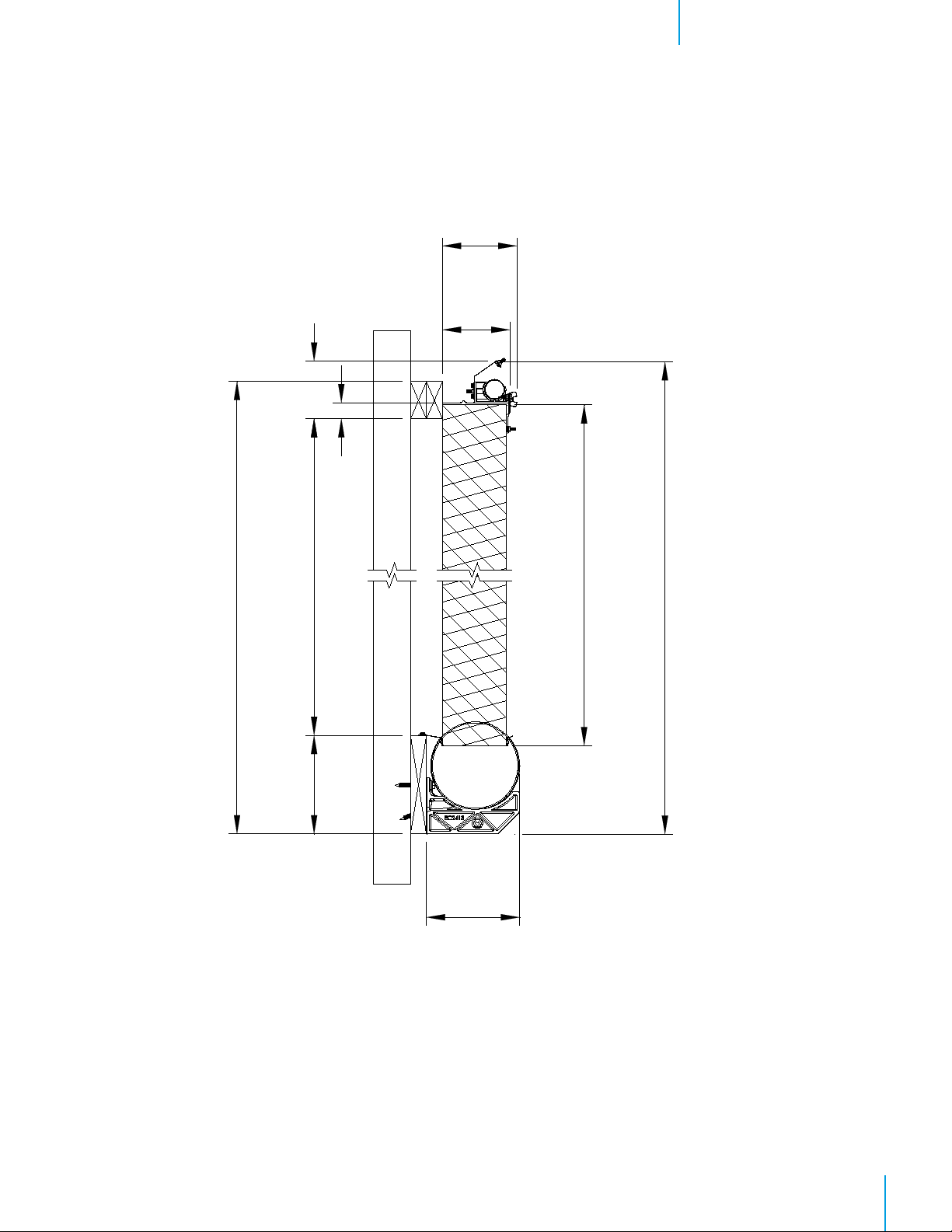
1.2 Dimensions
Unpacking the EquipmentChapter 1
7"
5³⁄₈"
PAD HEIGHT +10¹⁄₂"
57³⁄₄" for 5'H. -- 69¾ " for 6'H.
PAD HEIGHT --2¹⁄₄" Wall Opening
6³⁄₈"
1¹⁄₂"
60" (Pad Height)
PAD HEIGHT +12³⁄₈"
9¹⁄₄"
8³⁄₄"
QM1138r4
5© Munters Corporation, May 2021
Page 6
Installation Instructions
2.
2.1 Installation
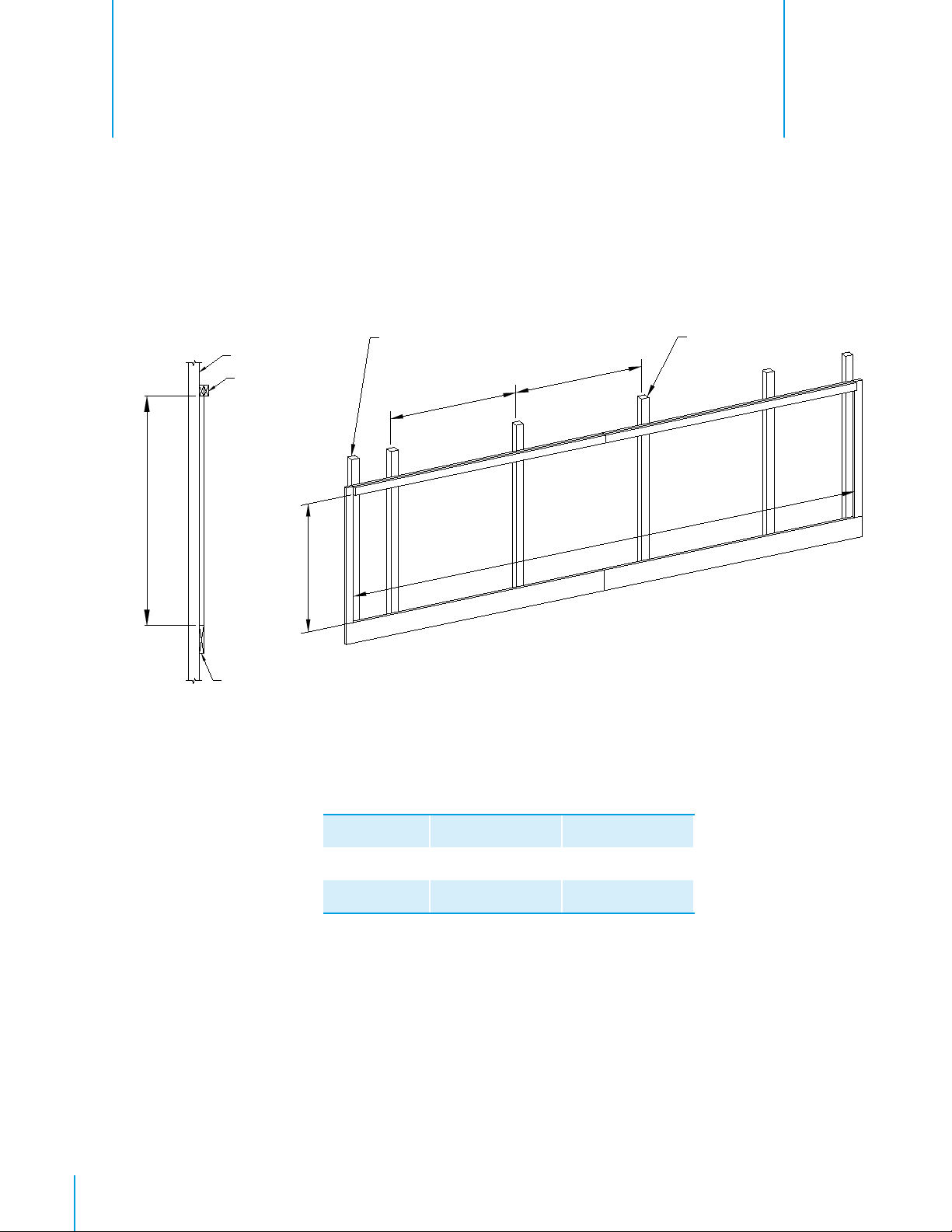
Step 1
Construct the framed opening to correct size according to Chart A (below) and your Cooling System size
using a 2x10, installed level, across the bottom, 2x4's up the sides and a double 2x4 across the top.
See Figure 1A and 1B
and Chart A.
Pad Height --2¹⁄₄"
Figure 1A
Building Post
Double 2x4
Top Framing
Pad Height --2¹⁄₄"
2x10 Bottom Framing,
Installed Level.
Extra Post at End of
Framing for Support
60"
Building Post
60" O.C.
60"
Pad Length
Figure 1B
6
QM1138r4
Example Length Height
Pad Length Pad Height --21⁄4”
80'L. x 5'H. 80'--0” 57
60'L. x 6'H. 60'--0” 69
Chart A
© Munters Corporation, May 2021
3
⁄4”
3
⁄4”
Page 7
Installation InstructionsChapter 2
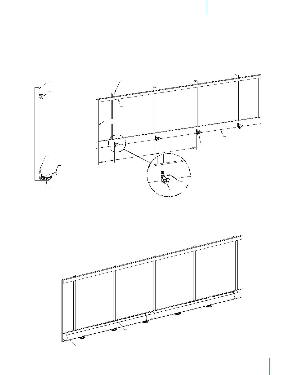
Step 2
The 8" Pipe Support Bracket should be installed every 60" O.C. into the building post, starting a maximum
of 24" from the End Framing. The holes in Bracket should be aligned vertically, with bottom flange flush
with bottom of level 2x10. Use holes in Bracket as a guide and pre-drill holes in the framing. Then fasten
Bracket using Lag Screw [B].
See Figure 2A and 2B
.
Building Post
Double 2x4
Framing
2x10 Framing
Pipe Support Bracket
Figure 2A
Lag Screw [B]
End Framing
24"
MAX.
Building Post
Double 2x4
Framing
2x10 Framing installed level
Pipe Support Bracket
60"
60"
Pipe Support Bracket
Lag Screw [B]
Figure 2B
Step 3
Starting on the end that the Tank will be, position the 8" Pipe in the Pipe Support Brackets with the non-bell
end and the Cut-Lines facing up and the pipe installed level.
Tank End
Cut-Lines on 8" Pipe
See Figure 3
.
Figure 3
8" Pipe non-bell end
QM1138r4
7© Munters Corporation, May 2021
Page 8
Installation InstructionsChapter 2
Step 4
With the 8" Pipe sitting in the Pipe Support Brackets, prepare the pipe with PVC Pipe Primer (not provided),
following the directions for use and drying. After priming, use heavy duty, heavy bodied PVC cement (not
provided) for pipe 8" diameter or larger, in accordance to the PVC cement directions.
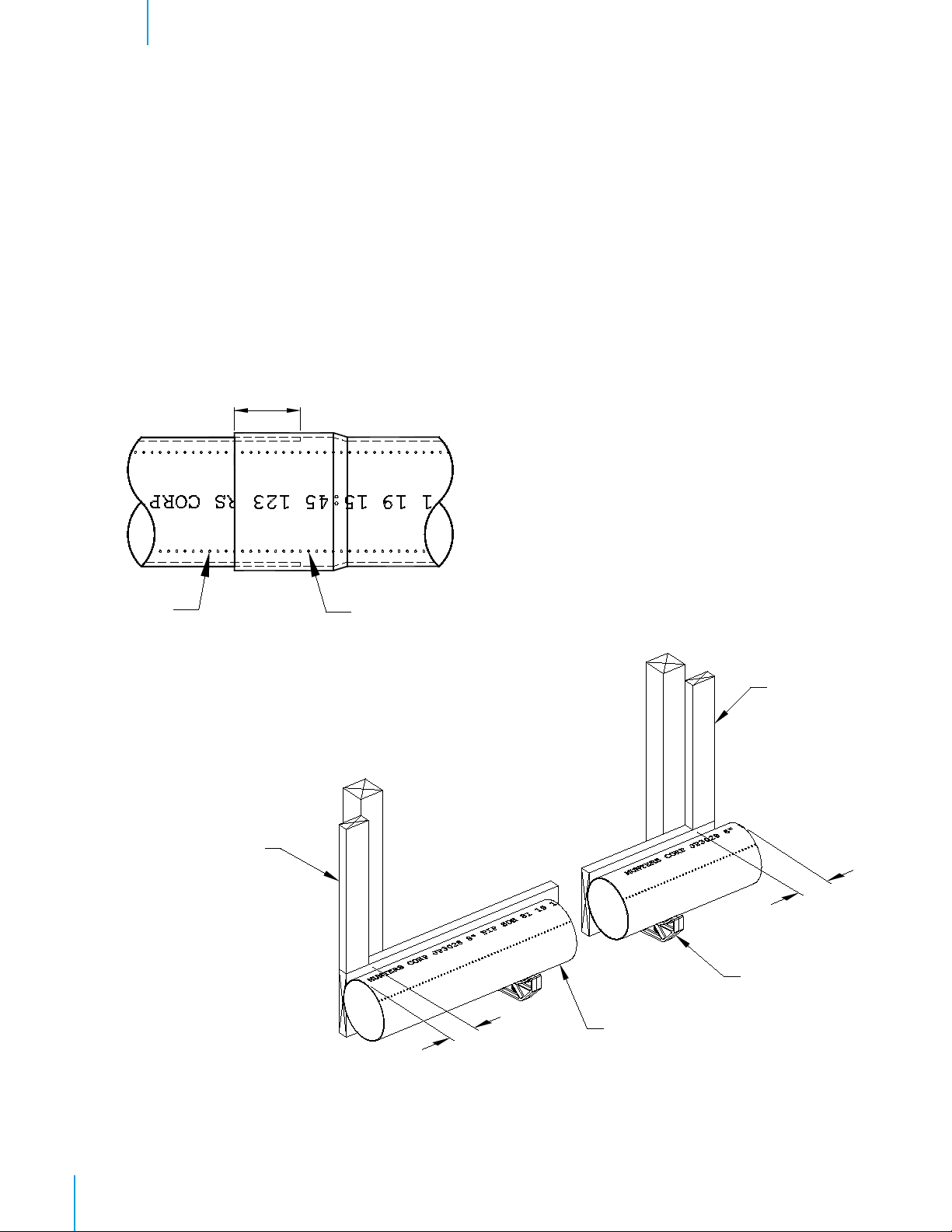
Step 5
Apply a generous amount of PVC cement to the inside of the bell end , and the outside of the non-bell end,
and slide together, 5" deep making sure the Cut-Lines from each pipe line up. See Figure 4A. Continue for
all sections of 8" Pipe making sure Cut-Lines from each pipe line up.
Step 6
On the Tank End position the 8" Pipe so that it extend past the inside edge of Framed Opening 4". On the
opposite end cut the 8" pipe so that it extends past the inside edge of Framed Opening 4". See Figure 4B.
5"
Cut-Lines
Figure 4A
End Framing
Cut-Lines
End Framing
4"
Pipe Support
Bracket
4"
8" Pipe
8
QM1138r4
Figure 4B
© Munters Corporation, May 2021
Page 9

Installation InstructionsChapter 2
Step 7
With the 8" Pipe sitting in the Pipe Support Brackets, positioned as stated in Step 6, mark a line between the
Cut-Lines ¹⁄₄" past the Framed Opening on each end of the pipe.
Step 8
After the PVC cement has set-up, cut along the outside edge of the Cut-Lines and across the marks at each
ends between the Cut-Lines. See Figure 5. Remove the cut piece and any other debris from the remaining
8" Pipe.
Inside Edge of Framing
Inside Edge
of Framing
Cut-Lines on
Cut-Lines on
8" Pipe
End Mark between Cut-Lines
8" Pipe
End Mark between
Cut-Lines
Figure 5
Step 9
Make sure the cut-out opening in the 8" Pipe is facing up. Starting from the tank end install the Drip
Collector into the 8" Pipe by inserting the side of Drip Collector with the flange into the pipe closest to
framing and then snapping front of Drip Collector into the front of the 8" Pipe. See Figure 6A and 6B.
Step 10
Once Drip Collector is snapped into the 8" Pipe make sure Drip Collector and pipe is level and the flange
is resting on top of 2x10 and Drip Collector is pushed up against the End Framing leaving a ¼ " gap
between the end of the Drip Collector and the cut end of the 8" Pipe, then secure in place using (5) 1"
Polebarn Screws [E]. See Figure 6B and 6C. Repeat for the remaining Drip Collectors, butting them up
to one another.
End Framing
Polebarn Screw [E]
Polebarn Screw [E]
Figure 6A
Drip Collector
8" Pipe
Drip Collector
8" Pipe
Drip Collector Flange
on top of 2x10
Figure 6CFigure 6B
QM1138r4
9© Munters Corporation, May 2021
Page 10

Installation InstructionsChapter 2
Step 11
Locate the Distribution Cap and the plastic Pipe Holder [D]. Fasten (4) Pipe Holders [D] to each Distribution
Cap using (2) Polebarn Screws [E]. See Figure 7A and 7B. Make sure all the Pipe Holders are installed in
the same direction.
Polebarn Screw [E]
Polebarn Screw [E]
Pipe Holder [D]
Distribution Cap
Distribution Cap
Pipe Holder [D]
Figure 7A Figure 7B
Step 12
The side of the Distribution Cap with the slots is the mounting flange. Starting at the Tank End, hold the
Distribution Cap mounting flange up to the Top Framing so that the end is flush with end of Top Framing
and the bend in the mounting flange is aligned with bottom edge of Top Framing and loosely secure in
place using (1) Polebarn Screw [E] in the end slots. See Figure 8A and 8B.
Distribution Cap
Mounting Flange with Slots
Polebarn Screw [E]
Top Framing
Long Edge of
Distribution Cap
10
QM1138r4
Top Framing
Bend in Mounting
Flange
Figure 8A
Polebarn
Screw [E]
Bend in Mounting
Flange
© Munters Corporation, May 2021
Polebarn
Screw [E]
Mounting Flange
with Slots
Figure 8B
Page 11

Installation InstructionsChapter 2
Step 13
After Distribution Cap is loosely secured to the Top Framing insert one piece of Cooling Pad at each end of
the Distribution Cap. Use these pieces to adjust the height of the Distribution Cap. Distribution Cap should
fit down tight to Cooling Pad. See Figure 9A and 9B. When the Distribution Cap is in place, make sure it
is level, then tighten the (2) Polebarn Screws [E] and then install (3) Polebarn Screws [E] in the remaining
slots.
Distribution Cap with
Pipe Holders
Cooling Pad
Cooling Pad
Distribution Cap with
Pipe Holders
Figure 9A
Figure 9B
Cooling Pad
QM1138r4
11© Munters Corporation, May 2021
Page 12

Installation InstructionsChapter 2
Step 14
Install the remaining Distribution Cap by butting the Mounting Flange of the next one up to the previous
one, with the Splash Guard overlapping the previous one. Make sure Distribution Cap is level and
securing in place with (5) Polebarn Screws [E]. See Figure 10. Then fasten the two Distribution Caps
together using (2) Hex Bolts [C] and Wing Nuts [A].
Wing Nut [A]
Hex Bolt [C]
Step 15
If installing a 6'H. system, fasten the End Panel
Extension to the bottom of the End Panel using
(1) Bolt [C] and Wing Nut [A]. The 1" flange
and 1½ " flange should match with the bolt
in the 1" flange. See Figure 11A. Position
End Panel so the 1¹⁄₂" Flange with 4/6 holes
rests against End Framing with the 1" Flange
away from the framing and the bottom tab
sticking into the slot between the end of the
Drip Collector and the end of the slot in the 8"
Pipe. Push the End Panel up against the Drip
Collector at the bottom and the Distribution
Cap at the top and attach to End Framing with
(4/6) Polebarn Screws [E]. See Figure 11B.
Repeat for opposite End Panel.
End Panel
Hex Bolt [C]
Wing Nut [A]
Polebarn Screw [E]
Mounting Flange of
Distribution Cap
Figure 10
End Framing
Polebarn Screw [E]
1" Flange
1¹⁄₂" Flange
12
QM1138r4
Figure 11A
Bolt [C]
Wing Nut [A]
End Panel Extension
End Panel
Drip Collector
Slot Between Drip
Collector and 8" Pipe
© Munters Corporation, May 2021
Figure 11B
Page 13

Installation InstructionsChapter 2
Step 16
Insert (1) Hex Bolt [C] into each Pipe Holder Bracket down the length of the system. See Figure 12.
Pipe Holder
Bracket
Hex Bolt [C]
Figure 12
Step 17
Assemble all the 1¹⁄₂" Distribution Pipe (with holes) together keeping the holes aligned. Secure pipes
together using (1) TEK Screw [F] at each joint. The Belled end of the pipe goes on the Tank End. At the
opposite end install the Slip Cap and secure it in place with (1) TEK Screw [F]. Snap the Distribution Pipe
into the Pipe Holder Brackets with the holes rotated 45°, so they are pointing towards the Splash Guard.
See Figure 13A, 13B and 13C.
TEK Screw [F]
Distribution Pipe
Holes in Pipe
Figure 13A
Top Framing
Figure 13B
Distribution Cap
Hole In Pipe
Distribution Pipe
Pipe Holder Bracket
Belled End of Distribution Pipe (Tank End)
Pipe Holder Bracket
Slip Cap
Figure 13C
QM1138r4
13© Munters Corporation, May 2021
Page 14

Installation InstructionsChapter 2
Step 18
Insert the first piece of Cooling Pad and slide it tight up to the End Panel. Be sure the directional arrows on
your Cooling Pad that should point upward and to the inside of the building. Making sure the pads are
tight together, install the remaining Cooling Pads, stopping at the last 2 pads. See Figure 14.
Step 19
Slide the next to the last piece of pad tight to the End Panel. Measure the opening that is left for the last
piece of pad at the top and bottom of the opening. If the opening is smaller than the width of the last piece
of pad, then use a hand saw to trim the last piece of Cooling Pad to fit the opening. Insert the last piece of
pad into the opening. See Figure 15.
Distribution Cap
Cooling Pad
End Panel
End Framing
Drip Collector
8" Pipe
Measure at Top
Figure 14
End Panel
Cooling Pad
14
QM1138r4
Measure at Bottom
8" Pipe with Drip Collector
Figure 15
© Munters Corporation, May 2021
Page 15

Installation InstructionsChapter 2
Step 20
Find the Pad Retainer and position it onto the bolts in the Pipe Holder Brackets and secure in place with (4)
Wing Nuts [A]. See Figure 16A and 16B.
Step 21
Install the remaining Pad Retainers and secure in on bolts using Wing Nuts [A]. Where the next Pad
Retainer overlaps the previous Pad Retainer secure with Hex Bolt [C] and Wing Nut [A] through slots.
See Figure 16C.
Pipe Holder Bracket
with Hex Bolt
Wing Nut [A]
Pad Retainer
Figure 16A
Step 22
On each end of the system install an End Panel Retainer Bracket
by inserting a Hex Bolt [C] in the hole in the End Panel and the
slot in the Pad Retainer, then placing the Bracket over these 2
bolts and securing in place using Wing Nuts [A].
See Figure 17.
Pipe Holder Bracket
with Hex Bolt
Wing Nut [A]
Pad Retainer
Figure 16B
Hex Bolt [C]
Wing Nut [A]
Figure 16C
Pad Retainer
End Panel Retainer Bracket
Hex Bolt [C]
Wing Nut [A]
Figure 17
End Panel Retainer Bracket
QM1138r4
15© Munters Corporation, May 2021
Page 16

Plumbing Installation
3.
3.1 Black Poly Tank
Step 23
Prepare the Black Poly Tank for attachment to the 8" Pipe by removing the flat interior surface of the 8" pipe
area. Cut the flat end leaving a minimum of ¹⁄₄" lip around the edge. See Figure 18. DO NOT CUT the
outer surface of the 8" pipe area, cutting the round surface will weaken the tank structure. See Figure 18.
Outer Surface
Cut the Flat End,
Leaving ¹⁄₄" Lip
8" Pipe Area
¹⁄₄"
Flat Interior Surface
to be Trimmed
Flat Interior Surface
to be Trimmed
BEFORE CUT
Figure 18
AFTER CUT
Step 24
Slide the Rubber Bellows Connector over the trimmed out 8" pipe area of the Black Poly Tank and secure in
place with the provided Hose Clamp positioned in the groove of the Rubber Bellows Connector.
See Figure 19.
Rubber Bellows
Connector
Hose Clamp
Ground or other support must be
capable of supporting 300 lbs.
Black Poly Tank
Trimmed
Out Interior
Surface
16
QM1138r4
Figure 19
© Munters Corporation, May 2021
Page 17

Plumbing InstallationChapter 3
Step 25
Clean any debris from inside the 8" Pipe. If needed flush-out the 8" Pipe with water before continuing.
Position the Tank with Bellows Connector at the end of the system and slide the Rubber Bellows Connector
over the end of the 8" Pipe and secure in place with the Hose Clamp (provided). See Figure 20. On the
other end of the system place the Black Rubber End Cap over the 8" Pipe and secure in place with Hose
Clamp (provided). See Figure 20.
8" Pipe
Hose Clamp
Rubber Bellows
Connector
8" Pipe
Black Poly Tank
Black Rubber End Cap
with Hose Clamp
Figure 20
Step 26
In some installations it may be necessary to bury or elevate the Black Poly Tank for proper alignment with
the 8" Pipe. In either case the ground or support must be capable of supporting 300 lbs. If using the
optional Cooling Tank Drain Kit, EC1630 for below grade or EC1635 for above grade, install it at this
time, following the instructions included with the kit. See Figure 21.
18⁵⁄₈"
Below Framed Opening
Figure 21
11³⁄₄"
Below 8" Pipe
QM1138r4
17© Munters Corporation, May 2021
Page 18

Plumbing InstallationChapter 3
Step 27
Cut overflow spout at an angle as shown. See Figure 22.
Step 28
Using the circular dimple in the tank, drill a 1¹⁄₁₆" dia. hole for the float valve. See Figure 22.
Step 29
Hold the Mounting Plate up to the Tank and align the hole in the tank and mounting plate and mark the 2
smaller holes and drill (2) ⁹⁄₃₂" dia. holes. Then attach mounting plate to tank using (2) HEX Head Bolts and
Flange Nuts. See Figure 22.
Drill ⁹⁄₃₂" dia. holes, use plate as template
Drill 1¹⁄₁₆" dia. hole
Overfl ow Spout
Overfl ow Spout Cut
Figure 22
HEX Head Bolts
Mounting Plate
Flange Nuts
18
QM1138r4
© Munters Corporation, May 2021
Page 19

Plumbing InstallationChapter 3
3.2 Float Valve
Step 30
Loosen or remove wing nut and bolt from Float/Valve Assembly and rotate the Float Assembly to the position
shown and tighten wing nut. See Figure 23A.
Step 31
Attach Float Valve Assembly to Tank using Washer, Nut and Garden Hose Adapter. See Figure 23A and 23B.
The ball of the Float Valve may need some adjustment to attain the proper water level in Tank. Proper water
level should be approximately 4" below the top of the 8" Pipe or level with the opening in the overflow spout.
Mounting Plate
Float Assembly
Valve Assembly
Nut
Bolt
Black Poly Tank Lid
4"
Wing Nut
Figure 23A
Valve Assembly
Black Poly Tank
Garden Hose
Connector
Washer
Garden Hose
Connector
Black Poly Tank
Figure 23B
QM1138r4
19© Munters Corporation, May 2021
Page 20

Plumbing InstallationChapter 3
Step 32
Cut Tank Lid to fit around the 1¹⁄₂" water supply
line connected to the pump. Make the cut match
the location of the pump. See Figure 24.
Figure 24
3.3 Optional Flush-out Kit (EC1507)
Step 33
If Flush-out Kit (EC1507) was purchased, remove TEK Screw and Pipe Cap from end of Distribution Pipe.
Assemble Flush-out Kit piping as shown. See Figure 25. Installation of 90° elbow and (1) 1¹⁄₂" x 10" pipe
is optional, depending on the desired direction of water flow.
Flush-out Kit Assembly is now complete.
1¹⁄₂" Coupler
1¹⁄₂" Distribution Pipe
1¹⁄₂" Valve
90° Elbow
20
QM1138r4
(2) 1¹⁄₂" x 10" Pipe Nipples
Figure 25
© Munters Corporation, May 2021
Page 21

3.4 Plumbing Layout with Submersible Pump
1¹⁄₂" Slip Ball Valve
EC1224
1¹⁄₂" Slip Elbow
EC1181
1¹⁄₂" Supply Line
JP3003
Plumbing InstallationChapter 3
1¹⁄₂" Slip Cap
EC1226
1¹⁄₂" In-Line Strainer EC1034
(2) 1¹⁄₂" Male Adapters
EC1176
1¹⁄₂" x 1¹⁄₂" x 1" Slip Tee
EC1221
1" Slip Ball Valve
EC1219
1" x 5" Pipe Nipple
EC1218
1¹⁄₂" Slip Union
EC1167
Poly Tank Lid Only
EC1346
1¹⁄₂" Male Adapter
EC1176
(2) Hose Clamp
KX1027
Rubber Bellows Connector
EC1339
8" Rubber Cap
with Clamp
EC1094
Black Poly Tank and Lid
EC1345
Float Valve Assembly
EC1613
Pump (Ordered Separately)
Figure 26
QM1138r4
21© Munters Corporation, May 2021
Page 22

Operation
4.
4.1 System Start-up
Step 1
Flush-out 8" Pipe and Black Poly Tank of any debris before filling with water.
Step 2
Prime pump with water.
Step 3
Turn on the electrical power and fresh water supplies.
Step 4
Activate the pump by setting the cooling thermostat below room temperature.
Step 5
Open the flow control valve at each cooling panel enough to completely saturate the pad material.
Step 6
Adjust the bleed-off valve to discharge water from the cooling system at a rate of 1 gallon per hour
per linear foot of cooling system. For example: The bleed off rate for a CB705EF system (70'L.)
would be 70 gallons per hour.
4.2 System Operation and Adjustment
Step 1
Set the cooling setpoint on the temperature controller as shown on your Munters Corporation ventilation
system drawing. If this is not available contact your Munters field representative for proper settings.
Step 2
Adjust the flow control valve at each cooling panel to give the pad material a "shiny wet" surface. Pad
material performs best when as much water as possible is used, but the flow should not be so great that
water falls from the material.
Step 3
If the pad material remains dry on one side (with fans running), even at full water flow, adjust the
distribution pipe so that the distribution holes are pointing towards the splash deflector.
Step 4
If water drips from the cooling panel's upper edge, the pad material may be loose in its frame. Correct this
by tightening the wing nuts on the front of the pad retainer to press it more firmly against the pad material.
Step 5
Water bleed-off is necessary to limit mineral deposits and other contaminants on the pad material by
assuring the continuous addition of fresh water. The rate of, 1 gallon per hour per linear foot of cooling
system, should be considered only as a starting point in determining the required amount of bleed-off. Due
to differences in water hardness, a trial and error process must be used to determine the correct rate for
your location.
22
After the cooling system has operated for a week or 2, the sump water may become discolored or a light
mineral coating may develop on the face of the pad material. If this occurs, increase the bleed-off rate
slightly and observe the tendency of the coating to increase or stabilize. If after an extended period of
time the mineral deposits become more visible, again increase the bleed-off rate.
Through this trial and error process a bleed-off rate will eventually be established at which the formation of
new deposits will cease. Slightly increase the rate from this point to compensate for fluctuations in water
hardness. The cooling system should now equalize and now more deposits should form.
QM1138r4
© Munters Corporation, May 2021
Page 23
Maintenance
5.
5.1 Minimum Maintenance Schedule
To maintain your cooling system in top condition, the recommendations given in this chart should be treated as
minimums. More frequent maintenance may be required at initial start-up, in certain climates, and in areas with
hard water conditions.
SCHEDULE
Weekly Monthly Yearly
Clean the foot valve or the pump fi lter screen X
Flush in-line strainer X
Check for dry streaks on pad material X
Clean debris from face of pad material X
Clean cooling control and sensor X
Clean cooling panel distribution pipe holes X
Clean cooling panel collection trough X
Drain and clean sump tank X
Clean/check fl oat valve X
5.2 Maintenance Checklist
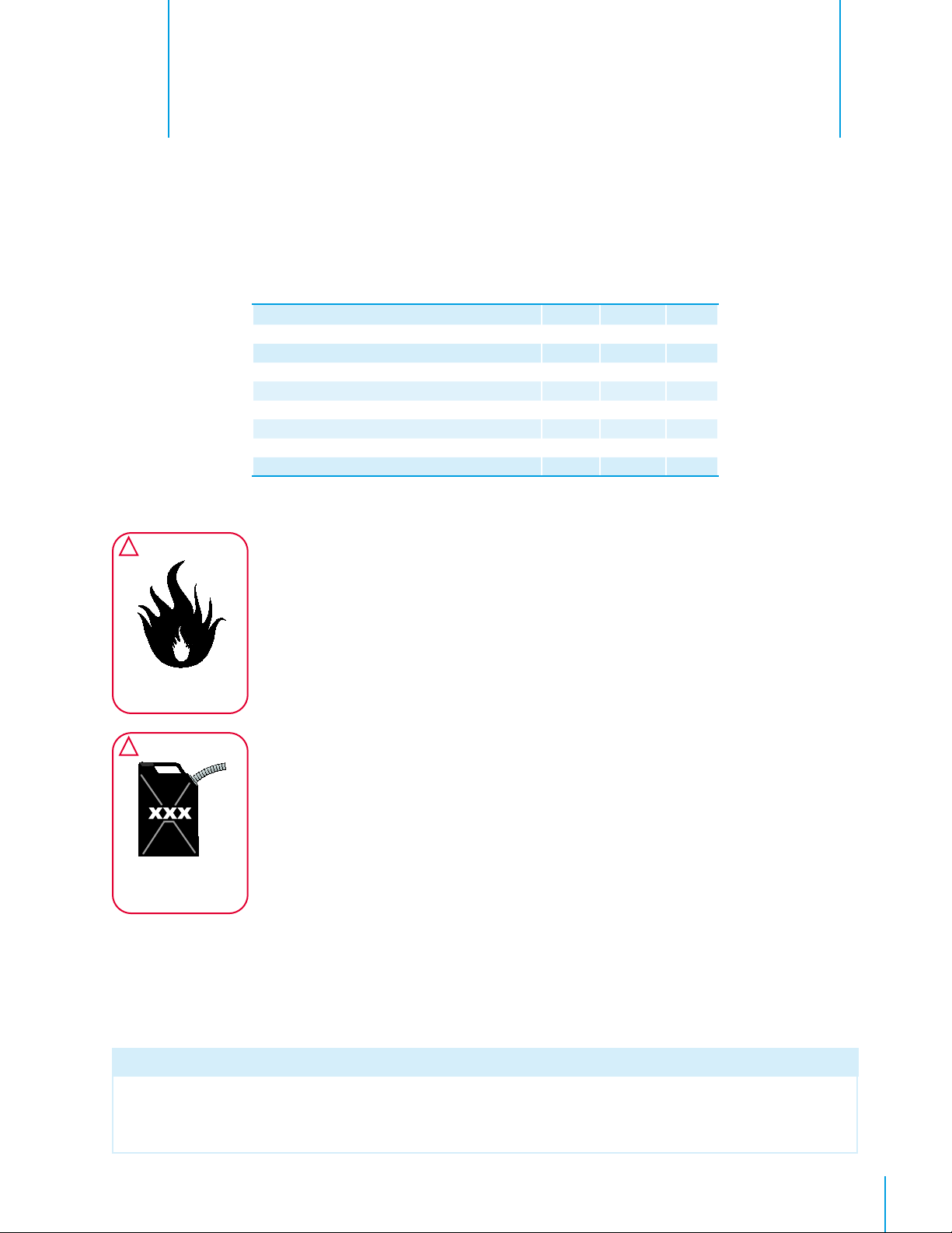
!
WARNING
Do Not allow fi re, sparks,
welding or smoking near
dry pads
!
WARNING
Do Not apply unapproved
chemicals or commercial
water treatments to sump
or sump water
Follow the guidelines below to prevent early pad failure and to get the maximum life from
your pads.
1. Reduce the number of on-off cycles. Do Not use 10 minute cycle timers on pumps.
2. Shade the pads and sump to minimize algae growth.
3. Dry the pads out completely each night to kill algae. A 24 hour timer may be installed
to shut pumps off at 10 PM and not allow them to come on until after 9 AM.
4. Bleed-off some water continuously to prevent concentration of minerals and dissolved
chemicals in sump. Start with 1 gallon per hour for each linear foot of cooling system
and adjust as necessary.
5. Drain and disinfect the water distribution system every three months to minimize algae,
fungus and mineral build-up.
6. Run the recommended quantity of water over the pads. The pump must provide ³⁄₄
gallon/minute for each linear foot of cooling system for 6" thick pad. For 4" thick pad,
provide ¹⁄₂ gallon/minute for each linear foot of cooling system.
7. Periodically check for leaks in water distribution system.
8. Avoid harmful contaminants such as dust, fumes, fertilizers, harsh cleaners and water
treatment chemicals.
9. Complete the items on the Maintenance Schedule listed above as required.
Warning:
DO NOT add unapproved chemicals or commercial water treatments to the sump or supply water. If the above
recommendations are followed and problems on the pad are observed such as algae growth, mineral deposits
or softening of the pad material, contact Munters Corporation for further recommendations.
QM1138r4
23© Munters Corporation, May 2021
Page 24

Exploded View
6.
24
QM1138r4
© Munters Corporation, May 2021
Page 25

Parts ListChapter 6
Item Catalog No
.
Description
Qty.
1 JP3028 8" Pipe with Cut Lines, PVC varies/foot
2
KS2462
3 EC2413
3
⁄8” x 3¹⁄₂” Lag Screw, HOT DIP GALV.
Pipe Support Bracket, PL
varies
varies/foot
4 EC2402 Drip Collector, 10'L., SS varies/foot
5 EC1400 End Panel for 5'H. System, SS 2
6 EC2400 Distribution Cap, 10'L., SS varies/foot
7 EC2401
Pad Retainer, 10'L., SS
varies/foot
8 EC2410 Pipe Holder, 1.5" Pipe, PL varies/foot
1
9 KS1019
10 KN2301
11 EC2404
12 EC1498
13* CEL1545061260M1
14 KS1404
* Catalog Number changes depending on type and size of pad.
⁄4”-20 x 1” Hex Bolt, SS
1
⁄4”-20 Wing Nut, Type-A, NY, Natural Color
End Panel Retainer Bracket, SS
Pipe, 1.5"Dia. x 10'-2¹⁄₂"L., with Holes, PVC
CELdek® Pad Material varies
#10-14 x 1” Seal Washer Polebarn Screw, ZP varies
varies/foot
varies/foot
varies/foot
2
QM1138r4
25© Munters Corporation, May 2021
Page 26

CB Evaporative Cooling System is developed and produced by Munters Corporation, Lansing, Michigan U.S.A. 1-800-227-2376
Munters Europe AB, Isafjordsgatan 1, P.O. Box 1150, SE-164 26 Kista, Sweden. Phone +46 08 626 63 00, Fax +46 8 754 56 66.
Munters Corporation 2691 Ena Drive Lansing, MI 48917 U.S.A. Phone +1 800-227-2376, Fax +1 517-676-7078
www.munters.us
Australia Munters Pty Limited, Phone +61 2 6025 6422, Brazil Munters Brasil Industria e Comercio Ltda, Phone +55 41 3317 5050, Canada/US Munters
Corporation Lansing, MI Phone +1 517 676 7070, China Munters Air Treatment Equipment (Beijing) Co. Ltd, Phone +86 10 80 481 121, Denmark Munters A/S,
Phone +45 9862 3311, India Munters India, Phone +91 20 3052 2520, Indonesia Munters, Phone +62 818 739 235, Italy Munters Italy S.p.A., Chiusavecchia,
Phone +39 0183 52 11,
+52 818 262 54 00, Russia Munters AB, Phone +7 812 448 5740, Singapore Munters Pte Ltd., Phone +65 744 6828, South Africa and Sub-Sahara Countries
Munters (Pty) Ltd., Phone +27 11 997 2000, Spain Munters Spain S.A., Phone +34 91 640 09 02, Sweden Munters AB, Phone +46 8 626 63 00, Thailand
Munters Co. Ltd., Phone +66 2 642 2670, Turkey Munters Form Endüstri Sistemleri A.Ş, Phone +90 322 231 1338, USA Munters Corporation Lansing, MI Phone
+1 517 676 7070, Vietnam Munters Vietnam, Phone +84 8 3825 6838, Export & Other countries Munters Italy S.p.A., Chiusavecchia Phone +39 0183 52 11
Japan Munters K.K., Phone +81 3 5970 0021, Korea Munters Korea Co. Ltd., Phone +82 2 761 8701, Mexico Munters Mexico, Phone
26
QM1138r4
© Munters Corporation, May 2021
 Loading...