

Page 1

0
DRYCOOL™ HD
Warranty Safety Installation Operation Maintenance
Residential and Light Commercial
Desiccant Dehumidifier
ovember 201
Page 2

Table of Contents i
Table of Contents
1. Introduction................................................................................................................................................1
1.1. Technical Description................................................................................................................................................1
1.2. Desiccant Wheel Operating Principle........................................................................................................................2
1.3. Intended Application..................................................................................................................................................3
1.4. Specifications............................................................................................................................................................4
1.5. Limited Warranty.......................................................................................................................................................5
2. Safety ..........................................................................................................................................................6
3. Installation..................................................................................................................................................7
3.1. Pre-Installation Requirements...................................................................................................................................7
3.2. Pre Checks and Inspection before Installation..........................................................................................................7
3.3. Ducting for Dehumidification .....................................................................................................................................9
3.4. Installation in Basement or Crawl Space with Existing Forced Air HVAC...............................................................11
3.5. Installation in an Attic with Existing Forced Air HVAC.............................................................................................12
3.6. Installation for Dehumidification for a Stand Alone Space......................................................................................12
3.7. Humidistat Installation Requirements......................................................................................................................13
3.8. Condensate Removal..............................................................................................................................................14
3.9. Optional Germicidal UV Light..................................................................................................................................14
3.10. Optional Active High Efficiency Electronic Filter .....................................................................................................16
4. Operating Instructions.............................................................................................................................17
4.1. Controls...................................................................................................................................................................17
4.2. Sequence of Operation ...........................................................................................................................................17
5. Maintenance and Service ........................................................................................................................18
5.1. Standard Air Filter ...................................................................................................................................................18
5.2. Electronic Filter........................................................................................................................................................18
5.3. Germicidal UVC Lights............................................................................................................................................19
5.4. UV Light Change and Safety Warnings ..................................................................................................................19
5.5. Troubleshooting.......................................................................................................................................................19
5.6. Recommended Maintenance Schedule..................................................................................................................20
6. Appendix: Unit Specific Information ......................................................................................................21
Unit Specific Information – Wiring Diagram, Sound Level Measurements, Fan Curves, Dimensional
Drawing
Updated: 11/1/2010 1:50:00 PM P00960167-1
Page 3

Introduction 1
1. Introduction
This manual includes installation, operation, and troubleshooting instructions for the DryCool™ HD desiccant
dehumidifier. The unit provides significant drying capability in a small package and utilizes a refrigerant circuit
in conjunction with a heat reactivated desiccant wheel to provide an efficient drying capability. Due to the
substantial capabilities of the desiccant wheel, the unit can continue to provide low supply dew point conditions.
The hybrid desiccant refrigeration cycle provides the most efficient small dehumidifier available. In addition,
the supply air is discharged at approximately space neutral temperature so that it does not add additional cooling
load to the space.
1.1. Technical Description
The DryCool™ HD uses a refrigeration system similar to an air conditioner to remove heat and moisture from
the incoming air. In addition a HoneyCombe® desiccant wheel downstream of the evaporator coil removes
further moisture from the airstream in a vapor state.
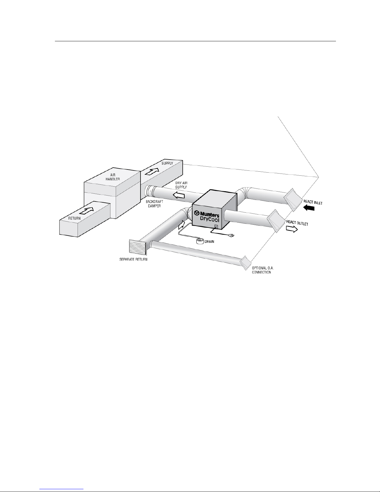
The HoneyCombe® desiccant wheel is operated with two separate air streams. The supply air stream is pulled
from the conditioned space and in controlled amounts from outside. The reactivation air stream is generally
taken entirely from outside. See Figure 1 below.
Within the closed circuit refrigeration system hot - high pressure refrigerant gas is routed from the compressor
to the condenser coil. Here the refrigerant is cooled and condensed by giving up its heat to the passing air. This
heated air is used to reactivate the HoneyCombe® desiccant wheel. The heat applied to the wheel allows
moisture to be driven off and discharged by the reactivation fan. Thus the reactivation air needs to be ducted to
the outside.
The refrigerant liquid then passes through a filter - drier and capillary tubing which causes the refrigerant
pressure and temperature to drop. It next enters the evaporator coil where the refrigerant absorbs heat from the
incoming air. The compressor then draws the cool refrigerant gas and compresses it to a high pressure and
temperature to repeat the process.
DryCool HD Operator and Maintenance Manual P00960167-1
Figure 1: DryCool™ HD Operating Principle
Page 4

Introduction 2
Figure 2: Refrigeration System of DryCool™ HD
The DryCool™ HD operates cost-effectively because all of the energy required for the operation of the
desiccant dehumidifier cycle is recovered from the refrigeration components. The system utilizes a humidistat
to cycle the capacity on when the humidity in the space is high and to cycle the capacity off when the space
humidity is at the desired condition.
Some benefits include, energy efficient and affordable dehumidification; environmentally friendly refrigerant
R-410a, compact size for installations in small spaces, assists in the prevention of mold, mildew and other
bacteria, low maintenance cost and fresh air ventilation.
1.2. Desiccant Wheel Operating Principle
1. The “Heart” of the DryCool™ HD system is the HoneyCombe® desiccant wheel. The wheel has a series of
air passages or channels arranged in a honeycomb pattern. The honeycomb material is nonmetallic and
does not react to bacteria. The passages inside the wheel are impregnated with a desiccant material, such as
silica gel.
2. When damp air is pulled through the supply air section of the wheel and contacts the desiccant it removes
moisture in a process known as “adsorption”. The removal of moisture causes the air to warm due to the
heat of vaporization of water in the air.
3. As the wheel rotates the stored moisture is moved from the supply air path to the reactivation air path.
Heated air in the reactivation air path passes over this section of the wheel, releasing large amounts of
moisture. We say the desiccant is “reactivated”. This process is constant as the desiccant wheel is
continually rotating.
4. See Sequence of Operation for a logic description of the DryCool™ HD desiccant dehumidifier.
To avoid the problems often caused by moisture and create a comfortable environment, a dehumidifier is
required or necessary to maintain relative humidity between 40-50% throughout the environment. Only
supplemental dehumidification provides indoor humidity control regardless of air conditioner operation or
outside moisture conditions.
DryCool HD Operator and Maintenance Manual P00960167-1
Page 5

Introduction 3
1.3. Intended Application
The DRYCOOL™ HD Dehumidifier is intended for installation in spaces that experience short or long term
high humidity conditions. The DRYCOOL HD is not suitable for pool areas. Use of the unit in pool areas will
void warranty. In order to efficiently control humidity levels, the area in which the dehumidifier is to be placed
must be free of water intrusion or excessive fresh air infiltration. Before installation, water intrusion or excess
air infiltration should be addressed. See Figure 3 for unit detail, inlet and outlet, supply and connection
information.
8”
REACT INLET
SQUARE TO
ROUND
(OPTIONAL)
8”
SUPPLY OUT
COND. COIL
SQUARE TO
ROUND
(OPTIONAL)
RETURN AIR
CONNECTION
8”
4”
O.A.
CONNECTION
DRAIN
EVAP.
ELECT.
UNIT DETAIL
8”
REACT OUTLET
ROUND OUT
Figure 3: DryCool HD Dehumidifier - Unit Detail
DO NOT use unit as a bench or table.
DO NOT place unit directly on structural members.
A secondary drain pan MUST be placed under the unit.
The DRYCOOL™ HD should be located near the existing air handling system to minimize the required
ductwork. The controls are remote from the unit and must be located in the space that is to be conditioned. The
controls are low voltage (24 volt) and should be connected with low voltage thermostat wire.
If fresh air ventilation is desired, thought should be given to the locatio n for the fresh air ducting. A 4” round
insulated duct will have to be installed on the unit and run to the outside of the structure to bring in fresh air.
The unit is not meant to condition more than 75 cfm of outside air. Consult local codes for necessary
distances from exhaust ports when installing fresh air return.
DryCool HD Operator and Maintenance Manual P00960167-1
Page 6

Introduction 4
1.4. Specifications
1.4.1. DryCool™ HD Dehumidifier Specifications
Model DRYCOOL™ HD
Electrical
Capacity
Operating Current
Power
Efficiency
Operating Temp
Installed Temp
Location
Air Flow
Supply Air Temp
Refrigerant
Unit Size
Unit Weight
Shipping Weight
Optional Filtration
*
115 / 60
120 Pints/day @ 80° F / 60% RH
6.8 Amps/Power consumption at full load
0.7kW - 0.8kW (Depending on load)
3.3 L/kW (7 Pints/kW)
Conditioned Space Limits: 45° F - 95° F
External Ducted* : 40° F – 140° F
Unducted Reactivation** : 40° F – 100° F
250CFM (See fan curves supplied in appendix)
Space Neutral (± 3° F )
Refrigerant Charge 28 oz. R410
24 L x 36 W x 16.5 H
140 lbs.
145 lbs
Merv 13- Active Electronic
* i.e. reactivation and process air inlets are externally ducted and connected to
“normal” non-attic space
**
** i.e. reactivation air comes from the space
Table 1: DryCool™ HD Dehumidifier Specifications
1.4.2. DryCool HD Performance and Psychometric Advantage
60
50
40
30
Leaving Dew Point ºF
25
Entering at 50% RH
Entering at 60% RH
65 70 75 80 85
Entering Temperature ºF
50 60 70 80 90
Dry Bulb Temperature °F
100
80
60
40
Humidity Ratio Grains of Moisture
per Pound of Dry Air (gr/lb)
DryCool HD Operator and Maintenance Manual P00960167-1
Page 7

Introduction 5
1.5. Limited Warranty
WARRANTY FOR MUNTERS DEHUMIDIFICATION EQUIPMENT, SYSTEMS AND PARTS
Your Munters DRYCOOL™ HD Dehumidifier is expressly warranted for a period of one (1) year from date of
purchase. This warranty extends to the original end user and may not be assigned to or transferred. Munters
warrants that for one (1) year after the date of original purchase the DRYCOOL™ HD Dehumidifier will
operate free from any defects in materials and workmanship. Munters exclusive obligation under this warranty
will be to supply, without charge, a replacement part for the dehumidifier which is found to be defective within
a one (1) year period from the date of purchase and which is returned not later than thirty (30) days after said
one (1) year period to Munters DRYCOOL™, Selma, TX together with proof of purchase of the dehumidifier.
THIS WARRANTY SHALL NOT OBLIGATE MUNTERS CORPORATION FOR ANY LABOR COSTS
AND SHALL NOT APPLY TO DEFECTS IN WORKMANSHIP OR MATERIALS FURNISHED BY YOUR
INSTALLER AS CONTRACTED TO DEFECTS IN THE DEHUMIDIFIER ITSELF.
IMPLIED WARRANTIES OF MERCHANTABILITY OR FITNESS FOR A PARTICULAR PURPOSE
SHALL BE LIMITED IN DURATION TO THE AFORESAID ONE YEAR PERIOD. MUNTERS
CORPORATION’S LIABILITY FOR INCIDENTAL OR CONSEQUENTIAL DAMAGES, OTHER THAN
DAMAGES FOR PERSONAL INJURIES, RESULTING FROM ANY BREACH OF AFORESAID IMPLIED
WARRANTIES OR THE ABOVE LIMITED WARRANTY IS EXPRESSLY EXCLUDED. THIS LIMITED
WARRANTY IS VOID IF DEFECT(S) RESULT FROM FAILURE TO HAVE THIS UNIT INSTALLED BY
A QUALIFIED HEATING AND AIR CONDITIONING CONTRACTOR. IF THE LIMITED WARRANTY
IS VOID DUE TO FAILURE TO USE A QUALIFIED CONTRACTOR, ALL DISCLAIMERS OF IMPLIED
WARRANTIES SHALL BE EFFECTIVE UPON INSTALLATION.
Some states do not allow limitations on how long an implied warranty lasts or the exclusion of limitation of
incidental or consequential damages, so the above exclusions or limitations may not apply to you.
This warranty gives you specific legal rights and you may also have other rights which vary from state to state.
DryCool HD Operator and Maintenance Manual P00960167-1
Page 8
Safety 6
2. Safety
The contents of this manual include suggested best working practices and procedures. These are issued for
guidance only and they do not take precedence over the individual responsibility and/or local safety regulations.
During installation and operation of this unit it is always each individual’s responsibility to consider:
Their own and others personal safety.
The safety of the unit through correct use of the equipment in accordance with the descriptions and
instructions provided in this manual and local/state safety guidelines.
Munters is concerned about the safety of all who use or services the DryCool™ HD desiccant dehumidifier unit.
There are parts inside the unit that can be dangerous if an untrained person tries to service the unit. Throughout
this manual, we have pointed out hazards that may occur in its. We have also listed the precautions necessary to
avoid these problems.
It is recommended that the user be informed about the use of safety symbols used in this manual by reading the
following information. The relevant safety information will be listed in each chapter or section.
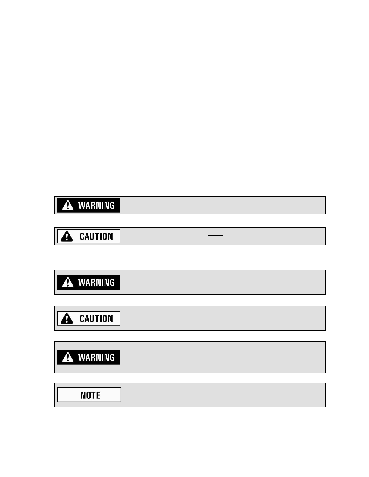
This manual uses two different types of warning messages to alert you of possible hazardous conditions:
Hazard or unsafe practice that may result in severe personal injury or
death.
Hazard or unsafe practice that could result in minor personal injury or
property damage.
Be aware of the following warnings while servicing the unit.
Only trained and qualified electricians should service the electrical
components of this unit. Repair to electrical components by non-certified
personnel may result in injury and/or damage to the unit.
Installation should be conducted by a qualified technician only and
Munters and Munters affiliates are not responsible for injuries and/or
damages caused by improper installation.
Improper installation, adjustments, alteration, service or maintenance can
cause property damage, injury or death. Read all install ati on , oper ating
and maintenance instructions thoroughly before installing or servicing this
unit.
READ AND UNDERSTAND ENTIRE MANUAL. FOLLOW ALL
INSTRUCTIONS AND READ MANUAL COMPLETELY. ENSURE ALL
SAFETY INSTRUCTIONS AND PRECAUTIONS ARE FOLLOWED.
DryCool HD Operator and Maintenance Manual P00960167-1
Page 9

Installation 7
3. Installation
3.1. Pre-Installation Requirements
Please note the following items related to this unit and its installation mu st be completed prior to sched uling th e
factory technician for startup.
All wiring (Power and Control), electrical components, control devices, and electrical service should
be completed in accordance with NFPA 70, NEC (National Fire Protection Association, National
Electrical Code). Wiring and components must also comply with all State and Local Code
requirements along with installation plans and unit specifications.
All venting, cooling, refrigeration, plumbing and piping should be installed per UMC, ASHRAE
(Uniform Mechanical Code, American Society Heating, Refrigeration and Air Conditioning Engineers)
requirements for building and energy efficiency. All components must also comply with all State and
Local Code requirements along with installation plans and unit specifications.
All air supply, ducting and connections must be completed per UMC, AMCA, and SMACNA
(Uniform Mechanical Code, Air Movement and Control Association - International Inc, Sheet Metal
and Air Conditioning Contractors National Association) specifications. All components must also
comply with all State and Local Code requirements along with installation plans and specifications.
3.2. Pre Checks and Inspection before Installation
The unit must be lifted carefully with assistance as necessary. Personnel must be capable of lifting weight
shown on dimensional drawing or Specifications Section 1.3. See Appendix for additional unit dimensions and
weight. If a lift is used, please use spreader bars that are two - four inches wider than the unit width to preven t
from squeezing the top of the unit. Failure to do so may damage the unit.
For proper mounting, review all drawings; dimensions, ducting, submittal package, notes on orientation and
positioning and confirm this information before installing unit(s).
Noise control issues should be taken into consideration when installing unit. Modern roof and construction is
normally lightweight. Where the DryCool unit is located over noise sensitive areas, noise may be a concern.
Generally, the distance between the roof-mounted equipment and the closest occupied spaces below the roof is
insufficient to apply standard sound control treatments.
A summary of sound level measurements are shown in the appendix. This information should be used as a
reference point for noise control considerations prior to placing unit. Simple Slow Time Weighing and Slow
Time Weighing Sound Level Equivalent charts for the Drycool HD™ can be viewed in the Appendix. Unit
sound level measurements were taken with system operating in the Airlab at Munters/Amesbury. Background
sound measurements were taken before and after testing and represent the ambient noise levels at the time the
system was sound level tested.
Upon unit arrival, inspect immediately for signs of shipping damage. If you do notice any damage, report it to
the shipping company and to Munters immediately.
1. Check all items in the shipment carefully against the bill of lading. Be sure all of th e listed items have been
received and none are missing.
2. Remove packing materials from unit to check the following items:
Unit is in position and evenly supported.
Unit is level.
Outside air is filtered before entering the building.
3. Check the electrical panels and controls:
Check for any signs of damage.
Check the tightness of all electrical connections. Carefully check the power wiring terminals.
DryCool HD Operator and Maintenance Manual P00960167-1
Page 10

Installation 8
3.2.1. Positioning the Unit
It is important that the intended installation site meets the location and space requirements for the unit in order
to achieve the best possible performance and trouble-free operation.
MAKE SURE THE UNIT IS LEVEL.
The appendix section shows the dimensional drawings for units. Allow specified clearances around the unit on
all sides for maintenance access. Units should have free access to all access panels and doors.
3.2.2. Installation Requirement Checklist
Check all items in this listing to insure proper installation prior to unit startup.
1. Check all electrical service and wiring.
All electrical service must be provided to accommodate the unit MCA (Minimum Circuit
Ampacity). It must be suitably protected against short cir cuit and gro und fault by a suitab le means
using the MOP (Maximum Overcurrent Protection).
2. Check and install all Duct connections.
Duct connections for supply and return air are adequate for the unit.
On supply discharge ductwork, allow for adequate length of 6ft or more of acoustical flex ducting
on the outlet side is available. See the installation section for detailed information. Details on
ducting standards can be found in SMACNA publication "HVAC Systems – Duct Design" and
Chapter 18 of 2008 ASHRAE HVAC Systems and Equipment Handbook.
3. Install and/or Check external piping, condensate drains, and drip pans make sure they are cleaned of
any debris.
The drain trap needs to be primed with water prior to start-up and after
extended periods of unit shut down (winter months).
4. Install and/or Check approved “P” trap on cooling and drain pan as required per local installations.
5. Install all humidistats; sensors, damper actuators, remote sensors and/or other humidity control
devices. Do not install the humidistat where it may not accurately sense the relative humidity, such as
near HVAC supply registers, exterior doors, or nea r a pool or spa .
6. Check installed ducting and connections for tightness.
3.2.3. Connecting Air Supply Duct
1. Air duct connections must be completed according to U.M.C., A.M.C.A., S.M.A.C.N.A., and/or state
and local code requirements. Refer to the plans and specifications supplied with the unit.
2. Where all flex-ducting is required be sure it is all UL listed. (This prevents ductwork from transmitting
vibrations).
3.2.4. Connecting Electrical Service
The DRYCOOL™ HD plugs into a common grounded outlet on a 15 Amp circuit. It draws between 6 and 7
Amps under normal operating conditions. If used in a wet area, a ground fault interrupter protected circuit is
required.
DryCool HD Operator and Maintenance Manual P00960167-1
Page 11

Installation 9
If an extension cord is required, it must have a minimum of 16 gauge conductors if less than 25 feet long, and
14 gauge if greater than 25 feet long.
1. Check for any signs of damage.
2. Ensure all electrical connections are tight. Carefully inspect power wiring terminals.
3. Electrical service and control wiring must comply with NEC and/or state and local code requirements.
4. The DryCool™ HD desiccant dehumidifier uses a common grounded outlet on a 15 amp circuit. Be
sure line voltage matches the voltage required by unit.
Be sure unit is properly connected to a power source with correct line
voltage. Line voltage that is too high can cause a SHOCK hazard and
damage unit. Correct line voltage is listed on electrical drawing.
3.3. Ducting for Dehumidification
The DRYCOOL™ HD Dehumidifier uses a unique arrangement of two air streams to accomplish the task of
providing cool dry air at high efficiencies. These are a supply air stream and a reactivation air stream. The
supply air stream is meant to dehumidify air for the space being controlled. The reactivation air stream
expels the water vapor collected by the desiccant dehumidification wheel.
MAKE SURE UNIT IS LEVEL.
3.3.1. Supply Air Ducting
A 11.5" W x 12" H square inlet located on the same side as an 8” round outlet is the supply air intake for the
unit. The square inlet can be connected directly to the return air duct coming from the central part of the
structure. This duct should draw air from the central part of the structure and supply air to the isolated areas of
structures like smaller rooms. Ductwork of the existing heating system can be used to supply air to the structure.
If the existing supply goes to isolated areas of the structure, discharge the supply of the DRYCOOL™ HD unit
into supply of the existing central system. DO NOT draw air directly from the kitchen,
laundry, or basement. You may draw air from a basement that is open to the structure. All flexible ducting
connected to the DRYCOOL™ HD unit should be UL listed.
The supply outlet of the DRYCOOL™ HD is located on the same side as the square supply inlet. A len gth of 6
feet or more of acoustical flex ducting on the outlet of unit will reduce air noise from the blower. A length of
flexible ducting on all DRYCOOL™ HD duct connections is recommended to reduce noise and
vibration transmitted to rigid ductwork in the structure.
aмЕнбеЦ=нЬЙ=aov`lli»=ea=кЙимбкЙл=ЕзелбЗЙк~нбзе=зС=нЬЙ=СзддзпбеЦ=йзбенлW=
=
aмЕн=pбтбеЦ: For total duct lengths up to 25', use a minimum 8" diameter round or equivalent rectangular.
=
For longer lengths, use a minimum 8" diameter or equivalent. Grills or diffusers on duct ends must not
excessively restrict air flow.
fëçä~íÉÇ=^êÉ~ë: Effective dehumidification may require ducting be branched to isolated, stagnant areas. Use
8" or larger diameter branch ducting to each of two or three areas; use 4" or larger to each of four or
more areas.
DryCool HD Operator and Maintenance Manual P00960167-1
Page 12

Installation 10
`зееЙЕнбеЦ= нз= ЙсблнбеЦ= es^`= лулнЙгл: An 8" check damper can be installed to prevent reverse flow
through unit. If the DRYCOOL™ HD is ducted to supply of a high static air h andler the ch eck damper may b e
placed in the unit supply duct.
When using the UV option, an 8’ long minimum supply air duct is required to be connected to the
square inlet.
3.3.2. Reactivation Air Ducting
A separate set of duct connections are provided for the DRYCOOL™ HD dehumidifier for reactivation air. The
reactivation air is meant to convey water vapor captured by the desiccant wheel away from unit and outside the
structure.
The reactivation outlet connection is an 8" ro und conn ection located on the opposite side of the 12 "W x 13.5"H
square supply air inlet. For total duct lengths up to 25’, use a minimum 8” diameter round or equivalent
rectangular. The duct should be brought to an outside wall or louver so that “wet” reactivation air is expelled
from the space and to the outdoors. Use a conventional dryer vent with back draft damper for penetrating wall if
infiltration is a concern.
3.3.3. Fresh Air Ducting
Fresh air can be brought into the structure by connecting a duct from outside to the DRYCOOL™ HD unit inlet
and by turning on the fan switch or activating the humidity control. The fresh air duct must be connected to the
return air duct of the central air system upstream of the DRYCOOL™ HD Dehumidifier. (See Figure 3 for air
flow illustration).
^ЗЗбнбзе~д=ЕзелбЗЙк~нбзел=~кЙ=~л=СзддзплW=
1. Outside air is filtered before entering the building.
2. Outside air will be dehumidified before entering if unit is running in dehumidificatio n mode.
3. Drawing air from outside and blowing inside aids in slightly pressurizing the structure. This helps
prevent dirty and humid air from entering elsewhere.
4. Adequate exhaust fans are recommended in bath rooms and kitchen.
5. Reactivation outlet must be separated 4’ minimally from the Fresh Air inlet.
In cold climates or areas where the outdoor dew point is low at times, ventilation can be used to dehumidify the
structure. This is accomplished by bringing the dry, low dew point air into the structure during these times. This
approach is often more economical than running the dehumidifier to remove excess moisture from the structure.
In cold climates, it is critical to adequately ventilate to reduce the inside moisture content to avoid moisture
accumulating in wall cavities. For example; in a house that experiences condensation on the interior surface of
windows during the winter, increasing the amount of ventilation will often cure the problem.
The DRYCOOL™ HD is designed to move 250 cfm. An insulated 4"diameter duct is generally sufficient to
provide up to 75 cfm of outside air. Remaining 175 cfm of return air can be mixed with this fresh air and ducted
into the supply intake of the DRYCOOL™ HD.
DryCool HD Operator and Maintenance Manual P00960167-1
Page 13

Installation 11
3.4. Installation in Basement or Crawl Space with Existing Forced Air HVAC
Figure 4: Conditioned Unventilated Basement Installation
Always select a return from a central location in the structure in an area that is always open to the rest of the
structure.
Do not use a return from a room that often may have its door closed. If the structure in which the unit is to be
installed has an existing forced air HVAC system, utilize the HVAC system to make the DRYCOOL™ HD unit
installation easier.
_~лЙгЙен=fелн~дд~нбзе: Install a separate 8" return duct for the DRYCOOL™ HD in a central area of the
structure. Duct the supply of the DRYCOOL™ HD to an 8" x 8" x 8" tee/damper that is 20% open to the
basement. Duct the other side of the tee to the air supply of existing HVAC system. Connect 8" ducts to the
reactivation inlet and outlet to supply ambient air for reactivation and to expel moist air outside the basement.
DryCool HD Operator and Maintenance Manual P00960167-1
Page 14
Installation 12
`ê~ïä=pé~ÅÉ= fåëí~ää~íáçå: Install a separate return for the unit in a central area of the structure. Duct the
supply of the DRYCOOL™ HD to an 8" x 8" x 8" tee/damper that is 20% open to the crawl space. Duct the
other side of the tee to the air supply of the existing HVAC system. Connect 8" ducts to the reactivation inlet
and outlet to supply ambient air for reactivation and to expel moist air outside the crawl space.
3.5. Installation in an Attic with Existing Forced Air HVAC
Figure 5: Attic Installation
ALWAYS install a secondary catch pan with a drain or float interrupt for condensate under the DRYCOOL™
HD in an attic.
Locate a separate return for the unit in a central area of the structure or draw air from return ductwork. Duct the
supply side of the unit to the air supply of the existin g HVAC system. Connect 8 " ducts to the reactivatio n inlet
and outlet to supply ambient air for reactivation and to expel moist air outside the attic.
3.6. Installation for Dehumidification for a Stand Alone Space
One of the benefits of a DRYCOOL™ HD is the delivery of dehumidified air to the space at approximately the
same temperature that enters the device. This allows an owner to simplify the installation for applications or
instances where it is desired to maintain humidity levels in one open space. In these applications the return air
from the space is connected directly to the unit and the dehumidified air can be delivered directly back into the
room without the need to mix it with cold air coming from a central air conditioning system.
If the space is a large common room and is open to other adjacent rooms, using the DRYCOOL™ HD can have
the effect of providing dehumidification to much larger connected areas or even a small structure. This is
because water vapor diffuses from areas of high vapor pressure to areas of low vapor pressure. When large
spaces are dehumidified with a unit, areas of low vapor pressure are created and will induce water vapor
movement from other connected open rooms without the need for ducting.
DryCool HD Operator and Maintenance Manual P00960167-1
Page 15

Installation 13
Figure 6 shows how the unit draws return air from the common space or a ventilated closet and discharges the
dehumidified air back into the space.
Figure 6: Installation for Stand Alone Space
The DRYCOOL™ HD requires mounting of the remote humidistat away from the discharge in an
area that is representative of the larger space. As with all of the installation configurations of a unit, the
reactivation air still needs to be ducted to and from outdoors as shown here.
3.7. Humidistat Installation Requirements
Install the remote humidistat in a central area of the structure where it will sense the relative hu midity of the
structure accurately. Do not install the humidistat where it may not accurately sense the relative humidity such
as near HVAC supply registers, near exterior doors, or near a pool or spa. The installer must supply the
wiring between the dehumidifier unit and the humidistat. Be sure to safely route the control wires to prevent
damage during installation. Be careful not to cross wires when connecting the DRYCOOL™ HD and
humidistat or damage to the transformer may result.
The humidistat of the DRYCOOL™ HD is powered by a low voltage circuit and must NEVER contact or be
connected to a high voltage circuit. The control wires leaving the unit and the humidistat are color coded to
prevent confusion. Be sure to consult the electrical schematic in this manual or the front panel of the unit before
making the control connections.
Please NOTE: Humidistat is not included. If purchased from Munters the humidistat will be supplied loose with
dehumidifier.
DryCool HD Operator and Maintenance Manual P00960167-1
Page 16

Installation 14
3.8. Condensate Removal
The DRYCOOL™ HD removes large amounts of moisture from the air
and the device must be connected to a drain line that will carry away the
excess water. A trap in the drain line is strongly recommended.
1. The unit requires a condensation drain that should be connected to a ¾” female pipe thread adaptor on
the front of the DryCool HD™. Install a proper P-trap in drain line and connect outlet to a suitable
drain.
2. The trap must be constructed according to U.M.C. and/or state and local code requirements. Refer to
plans and specifications supplied with unit.
3. The trap needs to be primed with water or cleaned prior to start-up and after any extended p eriods of
shutdown.
4. Care should be taken to install the drain line with a continuous slop of 1" per 10' to assure proper water
removal.
NOTE: The drain trap or its outlet should be checked and cleaned of debris annually or more often if deemed
necessary.
An optional condensate pump may be installed if a lift is required to dispose of the condensate. Please consult
your local supplier for a condensate pump kit.
For additional safety, Munters always recommends that a catch pan with
front switch be placed under the DRYCOOL™ HD.
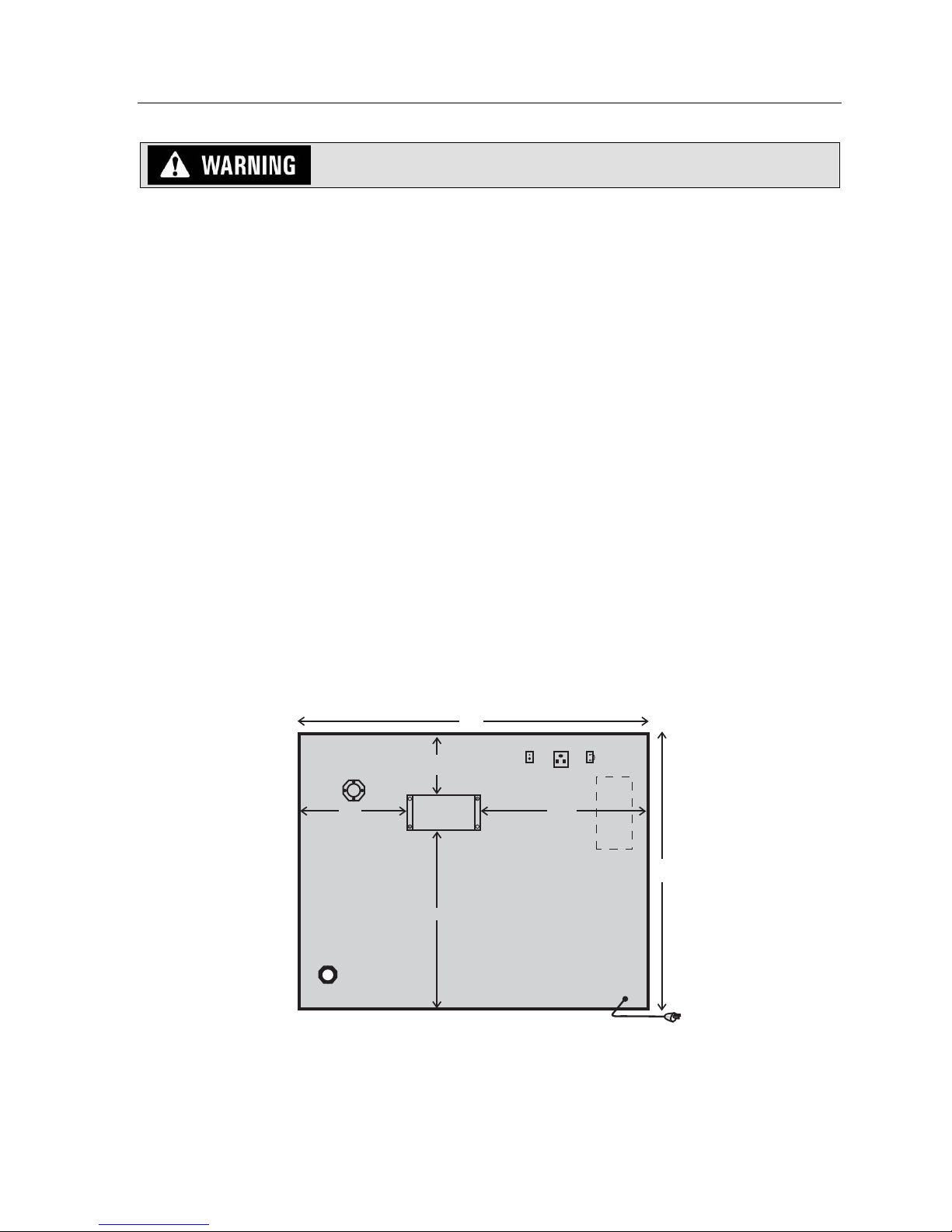
3.9. Optional Germicidal UV Light
An optional active germicidal UVC system can be provided with the Munters DRYCOOL™ HD. UVC is a type
of ultraviolet (UVC) energy in the 260-nanometer frequency. The “C” wavelength is the most germicidal in the
UVC spectrum. The “C” wavelength targets the DNA of microorganisms, causing cell death or making
replication impossible. The UVC energy kills or inactivates microbes, erad icating surface and airb orne mold, as
well as viruses and bacteria.
UVC is not an air filter. Rather it’s a UVC air purification system, based on Steril-Aire’s multi-patented
technology, used in thousands of schools, hospitals, and government and commercial buildings. This same
proven technology is now available for the structure.
The UVC air purification system then uses germicidal action to destroy the mold, bacteria and viruses that grow
and circulate in the air, before they travel around your space to trigger allergic reactions or spread disease.
Safety Notices: Improper installation, adjustment, alteration, service, maintenance, or use can cause fire,
electrical shock, or other conditions which may cause personal injury or property damage. Consult your local
authorized dealer or Munters Corporation for additional information or assistance.
DryCool HD Operator and Maintenance Manual P00960167-1
Page 17
Installation 15
Before performing maintenance or service on fixture, ensure unit is
unplugged. Electrical shock may cause injury or death.
Never expose eyes or skin to UVC light from any source. Wear gloves, face shield/glasses (per
ANSI Z87.1) and cover all exposed skin.
Do not touch Emitter glass without gloves. Damage to Emitter may result. Oil from fingerprints
will permanently etch glass of Emitter. If necessary, clean Emitter using optional cleaning kit.
Voltages outside of the range designed for the unit will void the warranty and do permanent
damage to the entire unit.
Emitter contains a small quantity of mercury. If an Emitter breaks, clean and dispose with care.
Note: Ensure that emitter is installed before power is applied. Installing emitter after the power has been
applied will trigger the “end of lamp life circuit” and emitter will fail to light! If this happens, shut off/deenergize power for 10 minutes and then turn power back on. Emitter will then light.
Disconnect power from unit
Remove installation hole plug. This black plastic plug is located on the same end of unit as the control
panel and is above the condensate drain outlet.
Install UVC lamp emitter according to installation instructions included with the emitter.
Attach UVC emitter power pack to the side of the DRYCOOL™ HD unit with sheet metal screws
provided with UVC emitter. Installation location noted in illustration below.
Plug power supply into the outlet on unit labeled “UV Light”.
Power can now be reconnected to unit.
Approx. 4”
DRAIN
UVC
POWER
PAC K
10”
24”
12.5”7.5”
16.5”
POWER
CORD
Figure 7: UVC Power Pack Installation
DryCool HD Operator and Maintenance Manual P00960167-1
Page 18

Installation 16
3.10. Optional Active High Efficiency Electronic Filter
An optional active electronic high efficiency air filter is available for the DryCool HD. This filter is rater 9095% efficient by ASHRAE Dust Spot Test Method 52-76. This filter is much more efficient than the standard
air filter and is able to catch much smaller particles that can aggravate allergies.
Particle Size Capture Efficiency
Typical Contaminant
3-10 Microns
1-3 Microns
.3-1 Microns
Pollen, mold, dust mites, hair spray
Auto emissions, lead dust, large bacteria
Smoke (tobacco, cooking), small bacteria, fine
dust, paint pigments
VOCs (odors, off gasses including formeldehyde
from carpets, furniture, and cleaning products
99%
98.6%
97%
40%
Munters Active Electronic Filter
This electronic filter is capable of cleaning air to the MERV 13 rating. In additon, the active electronic
capability of the filter removes other particles that can not be removed by standard passive filters.
Typical ContaminantParticle Size Capture Efficiency
3-10 Microns
1-3 Microns
Pollen, mold, dust mites, hair spray
Auto emissions, lead dust, large bacteria
99%
Not Eective
.3-1 Microns
DryCool HD Operator and Maintenance Manual P00960167-1
Smoke (tobacco, cooking), small bacteria, fine
dust, paint pigments
VOCs (odors, off gasses including formeldehyde
from carpets, furniture, and cleaning products
Conventional Passive Filter
Not Eective
Not Eective
Page 19

Operating Instructions 17
4. Operating Instructions
4.1. Controls
The DRYCOOL™ HD can be equipped with various accessories to enhance its operation. A remote humidistat
must be used with the unit.
Please NOTE: Humidistat is not included. If purchased from Munters the humidistat will be supplied loose with
dehumidifier.
4.1.1. Humidity Control Adjustment
Set the humidity control to the desired humidity level for the structure. Turning knob clockwise on the humidistat
results in a drier setting.
The dehumidifier will run continuously until the relative humidity (RH) is reduced to the humidity control dial
setting. Setting the humidity c ontrol to lower RH levels will NOT increase unit’s dehumidification rate; the uni t
will simply run longer to reduce area’s RH to the setting. The DRYCOOL™ HD (and refrigerant based
dehumidifiers in general) will reduce a conditioned space’s RH to a lower level. Settings below 40% are not
recommended.
4.1.2. Fan/Filter Switch
Turning ON the fan/filter switch on side of unit will cause the internal fan to run continuously, whether the unit is
dehumidifying or not.
This function is desirable if unit is used for air circulation and filtration to achieve maximum indoor air quality.
When the switch is ON; air will be constantly filtered through unit and circulated throughout house. When switch
is OFF; fan will operate only when humidity control calls for dehumidificati on.
The unit, long with either the high efficiency filter and/or the Germicidal UVC, can be used to perform tot al Indoor
Air Quality control for your structure.
4.2. Sequence of Operation
The ERV unit utilizes a humidistat to cycle the capacity on, when the humidity in the space is high and to cycle
the capacity off when the space humidity is at the desired condition.
If the humidity level in the space exceeds the control set point, the unit goes into dehumidification mode and the
HoneyCombe® desiccant dehumidifier wheel and DX cooling coils are energized. The desiccant wheel motor
is energized to rotate the wheel through the supply and reactivation air streams at a rate of 0.1 RPM. The
supply fan draws process air through the evaporator coil and the desiccant wheel. The reactivation air fan is
energized to draw outside air through the condenser coil and then through the desiccant wheel. The heat
rejected from the condenser coil heats up the reactivation air stream and drives the moisture from the desiccant.
This regeneration air is discharged to the outside atmosphere. The dehumidification process is continuous as
the desiccant wheel rotates through the supply and reactivation air streams. When the humidity in the space
returns to its control set point, the desiccant wheel and DX cooling system are de-energized. It should be noted
that the supply fan can be manually switched from “AUTO” to “ON” by pressing the switch on the side of the
unit.
DryCool HD Operator and Maintenance Manual P00960167-1
Page 20

Maintenance and Service 18
5. Maintenance and Service
5.1. Standard Air Filter
The DRYCOOL™ HD is equipped with air filters. These filters should be checked every three months.
Operating the unit with a dirty filter will reduce dehumidifier capacity and efficiency and may cause the
compressor to cycle off and on unnecessarily based on, or due to, high level pressure.
Under normal circumstances, filters in the unit should be cleaned or replaced quarterly or as labeled. A clean
filter is necessary to prevent damage to the dehumidifier and allow it to function at full capacity. To remove the
filters, first unplug or de-energize unit, then remove filter(s). To clean properly, flush with warm water and a
mild detergent solution or replace filter with new one. The filter sizes are 14 x 14 x 1 (process), 14 x 16 x 1
(reactivation) and are available from most local HVAC contractors. Once completed, return power/energize unit
and make sure all panels are tightly closed.
To access the air filter, slide the filter out of the side of unit. The filters can generally be vacuumed clean
several times before needing replacement. Replacement filters can be purchased locally. DO NOT operate the
unit without a filter. The heat exchange coils inside the unit could become clogged and require disassembl y to
clean.
5.2. Electronic Filter
The Polorized Electronic Air Filer uses a common 24V terminal for connection purposes. If necessary, an
optional accessory transformer is availble to plug into any 110V (AC) outlet to provide 24V (AC) power to the
unit. Please follow all specific instructions as provided by the manufacturer/vendor.
NOTE: Do not substitue any other 110VAC-24VAC transformers as damage could result to the units
electronics.
Installation of this filter should be done by a qualified electrician as
electrical wiring is required. Whenever installing or removing the filter, the
power to the unit should be turned off/de-energized and only returned once
task is completed.
5.2.1. Cleaning and/or Replacement Procedures
Filters or media pads should be cleaned and/or replaces depending upon household contaminant conditions. The
suggestion is after the first months use they should be cleaned or replace after initial cleanup of contaminants.
Filter can then be place on a regular maintenance schedule as required. Please follow the procedure listed
below.
Turn the thermostat fan switch to the “OFF” position.
Turn off/de-energize power to unit.
Open filter access door or grille.
Unplug the power supply cord from the air cleaner powerhead.
Open air cleaner and remove old filter/media pad and discard.
If dust has accumulated on outer screen of DH unit, clean with a dry brush or vacuum.
Replace new filter/media pad within center of frame.
Close air cleaner grille/door.
Return air cleaner to location in DH unit or return air grille.
Return power to air cleaner once installed securely.
Close filter access door or grille.
Turn thermostat fan back to the “ON” position. (For optimum results, DH unit should be run
continuously with the fan switch in the ON position, rather than the “AUTO” position.
Because of variations in humidity and temperature, the new filter/media pad may make a slight snapping sound
when first installed. This is normal and should stop and return to normal within 24 hours of operation.
DryCool HD Operator and Maintenance Manual P00960167-1
Page 21

Maintenance and Service 19
5.3. Germicidal UVC Lights
Continuously operated emitters need to be replaced annually to maintain design output. As a note, emitter
on/off cycles should be minimized in order to maximize emitter life.
No more than an ordinary light bulb - SteriLight’s unique Emitters™ are simply changed once a year.
SteriLight is virtually maintenance-free between change outs!
Do not look at UVC lights when operating without adequate eye protection.
UVC can cause damage to unprotected eyes.
5.4. UV Light Change and Safety Warnings
UV Light Saftey Warnings:
1. This unit contains a high energy ultra violet C-band (UVC) lamp. The UV radiation on this product is
in the highest ANSI/IENSA RP-27.3-07 group, Risk Group 3 (RG-3). Radiation at this level should not
be allowed to irradiate human tissue. The UV lamp is to be de-energized before changing the bulb or
servicing the dehumidifier. Precautions are to be taken to ensure that service personnel are adequately
protected at all times from UC radiation. RG-3 radiation is also present near the inlet of the duct. A
minimum of 8” (ft) un-perforated ducting is required to be connected to the inlet when the UV light
option is used.
2. Ultra violet radiation is present inside unit. Avoid exposure. Always wear protective clothing.
Exposure may cause cancer and premature aging of the skin. Always wear protective eyewear. Failure
to do so may result in severe burns or long term injury to the eye. Never look directly into lamp. As
with natural sunlight, exposure can cause eye and skin allergy o r allergic reactions. Medications or
cosmetics may increase sensitivity to the UV radiation. Consult a physician before operating this
product, if you are using medications or have a history of skin problems or believe yourself especially
sensitive to sunlight.
5.5. Troubleshooting
Fan runs with fan switch and ventilation timer OFF, but compressor cycles on & off.
Low ambient temperature and/or humidity causing unit to cycle through defrost mode.
Dirty air filter(s) or air flow restricted.
Defective compressor overload.
Defective compressor.
Fan does not run with fan switch in either position. Fan does not run with ventilation timer activated.
Compressor runs briefly but cycles on & off with humidity control turned to ON.
Check for 120V & 24V
Loose connection in fan circuit.
Obstruction prevents fan impeller rotation.
Defective fan.
Defective fan relay.
Evaporator coil frosted continuously, low dehumidifying capacity.
Dirty air filter(s) or air flow restricted.
Low refrigerant charge.
Dirty evaporator coil
DryCool HD Operator and Maintenance Manual P00960167-1
Page 22

Maintenance and Service 20
Emitter does not light
Turn off power for 10 minutes and then turn power back on.
Check line voltage.
Check wiring to emitter.
Replace emitter.
Replace power supply.
Low Output or visibly weak light
Replace emitter with new unit.
Check line voltage.
Check wiring to emitter.
Red/Orange light
Check ambient temperature, light will not operate properly below 35°F.
Follow actions for “Low Output”.
Servicing the DRYCOOL™ HD with its high pressure refrigerant system
and high voltage circuitry presents a health hazard which could result in
death, serious bodily injury, and/or property damage. Only qualified
service people should service this unit.
5.6. Recommended Maintenance Schedule
The following table lists recommended maintenance schedules. For detailed instructions on each procedure
consult Munters or the appropriate supplier for that part.
5.6.1. Annual Maintenance Schedule
Check This Location Monthly Quarterly Annually
Inspect Ductwork
Replace Standard Air Filters
Replace Electronic Air
Filters
Germicidal UVC Lights
Drain Trap
Supply Air Outlet/Inlet
As Labeled
As Labeled
As Labeled within unit
Per Location
Table 3: Annual Maintenance Schedule
Note: The frequency of all maintenance activities should be adju sted as required per the area of installation.
Dirty or dusty environments may require more frequent scheduling of maintenance.
DryCool HD Operator and Maintenance Manual P00960167-1
Page 23

Appendix: Unit Specific Information 21
6. Appendix: Unit Specific Information
Wiring Diagram
Sound Level Measurements
Fan Curves
Dimensional Drawing
Munters Corporation
Tel: (800) 843-5360
E-mail: dhinfo@munters.com
www.munters.us
DryCool HD Operator and Maintenance Manual P00960167-1
Page 24

Appendix: Unit Specific Information 22
DryCool HD Operator and Maintenance Manual P00960167-1
Figure 9. Wiring Diagram Pictorial
Page 25

Appendix: Unit Specific Information 23
70.00
60.00
50.00
40.00
30.00
20.00
10.00
0.00
10 100 1000 10000
Freqency (Hz)
DryCool Sound Levels with Background Noise eliminated
Average Sound Levels with Background Noise Eliminated
Frequency Level
Broadband
Broadband
32
63
125
250
500
1000
2000
4000
8000
64.17
53.57
62.24
52.79
57.86
50.46
50.20
49.85
44.69
38.82
28.95
Table 2: Average Sound Levels with Background Noise Levels Eliminated
DryCool HD Operator and Maintenance Manual P00960167-1
Page 26
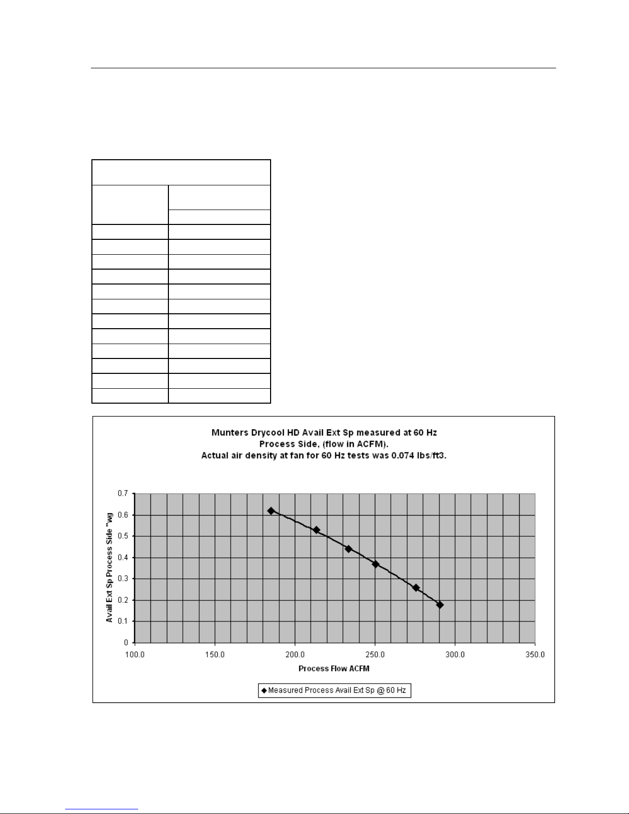
Appendix: Unit Specific Information 24
Munters DryCool HD drier testing and analysis for measurement taken on process side of system. Available
external Sp measured at 60Hz, 81 deg F Tro.
Munters Drycool HD Process Side
Process
Airflow
Available Ext Sp
"wg
ACFM at fan 60 Hz measured
185.0 0.62
185.0 0.62
213.3 0.53
213.3 0.53
233.6 0.44
233.6 0.44
250.2 0.37
250.4 0.37
275.7 0.26
275.6 0.26
290.4 0.18
290.6 0.18
DryCool HD Operator and Maintenance Manual P00960167-1
Page 27

Appendix: Unit Specific Information 25
g
Munters DryCool HD drier testing and analysis for measurement taken on react side of system. Available
external Sp measured at 60Hz, 81 deg F Tro.
Munters Drycool HD React Side
React
Airflow
Available Ext Sp
"wg
ACFM at fan 60 Hz measured
294.0 0.24
294.1 0.24
278.8 0.3
278.8 0.3
249.2 0.43
249.2 0.43
228.3 0.5
228.2 0.5
200.7 0.59
200.7 0.59
183.1 0.65
183.1 0.65
M u nter s Drycool HD Avail Ext Sp measur ed at 60 Hz.
Actual air density at fan for 60 Hz tests was 0.074 lbs/ft3.
React Side, (f low is in ACFM).
0.7
0.6
0.5
0.4
0.3
0.2
Avail Ext Sp React Side "w
0.1
0
100.0 150.0 200.0 250.0 300.0 350.0
DryCool HD Operator and Maintenance Manual P00960167-1
Reac t Flow ACFM
M easured Reac t Avail Ex t Sp at 60 Hz
Page 28

Appendix: Unit Specific Information 26
DryCool HD Operator and Maintenance Manual P00960167-1
Figure 10. Dimensional Drawing
Page 29

Appendix: Unit Specific Information 27
DryCool HD Operator and Maintenance Manual P00960167-1
 Loading...