

Page 1

Originalinstructions
Usermanual
ComDryM160L
Desiccantdehumidier
190TEN-1098-D1404©MuntersEuropeAB2014
Page 2
Importantuserinformation
Intendeduse
Muntersdehumidiersareintendedtobeusedforthe
dehumidicationofair.Anyotheruseoftheunit,or
usewhichiscontrarytotheinstructionsgiveninthis
manual,cancausepersonalinjuryanddamagetotheunit
andotherproperty.
Nomodicationoftheunitisallowedwithoutprior
approvalbyMunters.Attachmentorinstallation
ofadditionaldevicesisonlyallowedafterwritten
agreementbyMunters.
Warranty
Thewarrantyperiodisvalidfromthedatetheunit
leftourfactory,unlessotherwisestatedinwriting.
Thewarrantyislimitedtoafreeexchangeofpartsor
componentswhichhavefailedasaresultofdefectsin
materialsorworkmanship.
Allwarrantyclaimsmustincludeproofthatthe
faulthasoccurredwithinthewarrantyperiodand
thattheunithasbeenusedinaccordancewiththe
specications.Allclaimsmustspecifytheunittypeand
fabricationnumber.Thisinformationisstampedonthe
identicationplate,seesectionMarking.
Itisaconditionofthewarrantythattheunitforthe
fullwarrantyperiodisservicedandmaintainedas
describedinsectionServiceandmaintenance.Theservice
andmaintenancemustbedocumentedforthewarranty
tobevalid.
Safety
Informationaboutdangersareinthismanualindicated
bythecommonhazardsymbol:
W
ARNING!
W W
ARNING! ARNING!
Indicatesapossibledangerthatcanleadtopersonalinjury .
CA
UTION!
CA CA
UTION! UTION!
Indicatesapossibledangerthatcanleadtodamagetothe
unitorotherproperty ,orcauseenvironmentaldamage.
NOTE!Highlightssupplementaryinformationforoptimal
useoftheunit.
ConformitywithDirectives
Thedehumidierisinconformitywiththeessential
safetyrequirementsoftheMachineryDirective
2006/42/EC,theLowVoltageDirective2006/95/EC,
theRoHSDirective2011/65/ECandtheEMC
Directive2004/108/EC.Thedehumidieris
manufacturedbyanISO9001:2008accredited
manufacturingorganisation.
Copyright
Thecontentsofthismanualcanbechangedwithout
priornotice.
NOTE!Thismanualcontainsinformationwhichis
protectedbycopyrightlaws.Itisnotallowedtoreproduceor
transmitanypartofthismanualwithoutwrittenconsentfrom
Munters.
Pleasesendanycommentsregardingthismanualto:
MuntersEuropeAB
TechnicalDocumentation
P.O.Box1150
SE-16426KISTASweden
e-mail:t-doc@munters.se
iiImportantuserinformation190TEN-1098-D1404
Page 3

Tableofcontents
Importantuserinformation...............ii
Intendeduse...........................
Warranty...............................
Safety..................................
ConformitywithDirectives............
Copyright..............................
Tableofcontents...........................iii
1Introduction.................................1
1.1Aboutthismanual.....................
1.2Unintendeduse........................
1.3Safety..................................
1.4Marking................................
2Principleofoperation......................4
3Transport,inspectionandstorage.......5
3.1Transport..............................
3.2Inspectionofdelivery..................
3.3Storingtheequipment................
4Installation...................................6
4.1Safety..................................
4.2Closedsystem.........................
4.3Opensystem..........................
4.4Siterequirements.....................
4.5Installationoftheunit..................
4.6Ductsandhoses.......................
4.7Connectingthedrainhose............
4.8Electricalconnections................
4.9Expandingthesystem................
4.10Accessories...........................
5Controlpaneloverview....................13
6Operation....................................14
6.1Safety..................................
6.2Introduction............................
6.2.1Humiditycontrol................
6.2.2Fanmodes.....................
6.2.3Fanspeed......................
6.3Initiationandstart.....................
6.3.1Bootthecontrolsystem........
6.3.2Startthedehumidier..........
6.4Stopthedehumidier.................
6.5Emergency............................
ii
ii
ii
ii
ii
1
1
1
3
5
5
5
6
6
7
7
8
9
9
10
11
12
14
14
14
14
14
15
15
15
16
6.6Automaticstartafterpowerfailure....
6.7Navigatethemenus...................
6.8Accessthecontrolsystem............
6.9Changethesystemsettings..........
6.10Resetanalarm........................
6.11Resetthecounters....................
6.12Serviceintervalalarm.................
6.13Restorethedefaultsettings...........
6.14Accesslevels..........................
7Menusandparameters....................24
7.1Humidity...............................
7.1.1Internalcontrollingsensor.....
7.1.2Externalcontrollingsensors..
7.2Runtime...............................
7.3Power..................................
7.4Temperature...........................
7.5Functions..............................
7.5.1Processfanspeed.............
7.5.2Processfanmode..............
7.5.3Humiditycontrolandunits.....
7.5.4Displayinformation............
7.6Alarm...................................
7.7Min,maxanddefaultvalues..........
7.7.1Humidity........................
7.7.2Servicetime....................
7.7.3Functions.......................
8Serviceandmaintenance.................35
8.1General................................
8.2Maintenanceschedule................
8.3Processairlterchange..............
9Faulttracing.................................37
10T echnicalspecication....................39
10.1Dimensionsandservicespace.......
10.2Capacitydiagram.....................
10.3Fancurveprocessair.................
10.4T echnicaldata.........................
11Scrapping....................................42
12ContactMunters............................44
16
16
17
18
19
20
21
22
23
23
24
25
25
26
27
28
30
30
30
30
31
33
34
34
34
34
35
35
36
39
40
40
41
190TEN-1098-D1404Tableofcontentsiii
Page 4
ComDryM160L
1Introduction
1.1Aboutthismanual
Thismanualiswrittenfortheuserofthedehumidier.Itcontainsnecessaryinformationforhowtoinstall
andusethedehumidierinasafeandefcientway.Readthroughthemanualbeforethedehumidieris
installedandused.
ContactyournearestMuntersofceifyouhaveanyquestionsregardingtheinstallationortheuseofyour
dehumidier.
Thismanualmustbestoredinapermanentlocationclosetothedehumidier.
1.2Unintendeduse
■Thedehumidierisnotintendedforoutdoorinstallation.
■Thedehumidierisnotintendedforuseinclassiedareaswhereexplosionsafetycompliantequipment
isrequired.
■Thedehumidiermustnotbeinstallednearanyheatgeneratingdevicesthatcancausedamagetothe
equipment.
NOTE!Whenadehumidierisplacedinabuildingwithradonitisnecessarytocontactanexperttosecurethe
bestoverallsolution.Allchangesaffectingtheventilationorthepressurebalanceinthebuildingcanresultina
changedconcentrationofradon.
CA
UTION!
CA CA
UTION! UTION!
Donotsit,stand,orplaceanyobjectsontheunit.
1.3Safety
Everymeasurehasbeentakeninthedesignandmanufactureofthedehumidiertoensurethatitmeetsthe
safetyrequirementsofthedirectivesandstandardslistedintheECDeclarationofConformity.
Theinformationinthismanualshallinnowaytakeprecedenceoverindividualresponsibilitiesorlocal
regulations.
Duringoperationandotherworkwithamachineitisalwaystheresponsibilityoftheindividualtoconsider:
■Thesafetyofallpersonsconcerned.
■Thesafetyoftheunitandotherproperty.
■Theprotectionoftheenvironment.
ThetypesofdangersthatareindicatedinthismanualaredescribedinsectionImportantuserinformation.
1Introduction190TEN-1098-D1404
Page 5

ComDryM160L
W
ARNING!
W W
ARNING! ARNING!
-Theunitmustnotbesplashedwithorimmersedinwater.
-Allelectricalinstallationsmustbecarriedoutbyaqualiedelectricianandinaccordancewithlocalregulations.
-Theunitmustbeconnectedtoanearthedelectricaloutlet.
-Donotconnecttheunittoothermainsvoltagethanspeciedontheidenticationplate.
-Donotoperatetheunitifthepowerplugorcordisdamaged,riskofelectricalshock.
-Donotpulltheplugwithwethands,riskofelectricalshock.
-Donotinsertngersoranyotherobjectsintotheairvents,rotatingfansareinside.
-Donotcovertheunitasthatcanblockairintakeoroutletandcauseare.
-Iftheunithasoverturned,cutthepowerimmediately.
-AlwayscontactMuntersforserviceorrepair.
190TEN-1098-D1404Introduction2
Page 6
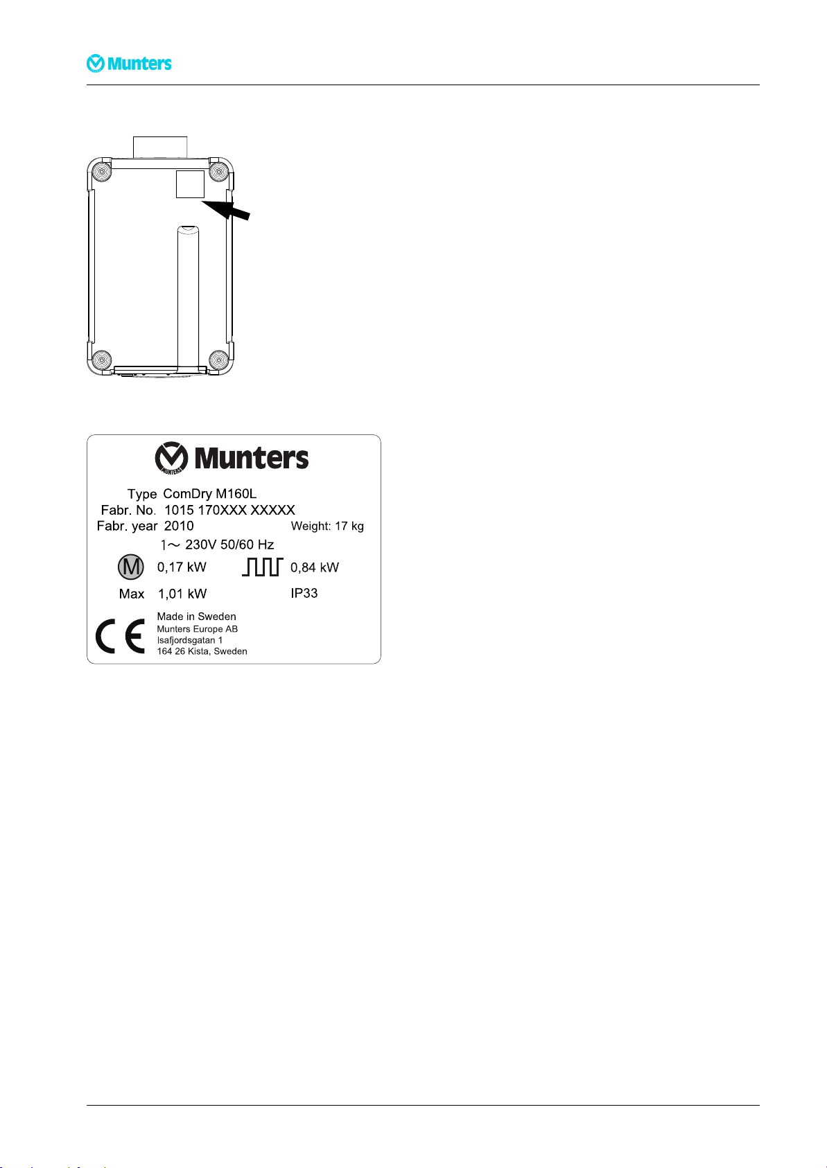
1.4Marking
Type
Fa b r. No.
Fa b r. year
0,17 kW
Max 1,01 kW
1015 170XXX XXXXX
2010
ComDry M160L
00·
·
230V 50/60 Hz
Mad e in S we de n
Munte rs E urop e AB
Isa fjord sga tan 1
16 4 2 6 Kista , S wede n
Weigh t: 17 kg
IP3 3
0,84 kW
oHS
M
Figure1.1Identicationplateposition
ComDryM160L
Figure1.2Identicationplate,anexample
Explanationof"Fabr.No."ontheidenticationplate:
10:Yearofmanufacture
15:Weekofmanufacture
170XXX:Articlenumber
XXXXX:Serialnumber
3Introduction190TEN-1098-D1404
Page 7
ComDryM160L
1
3
2
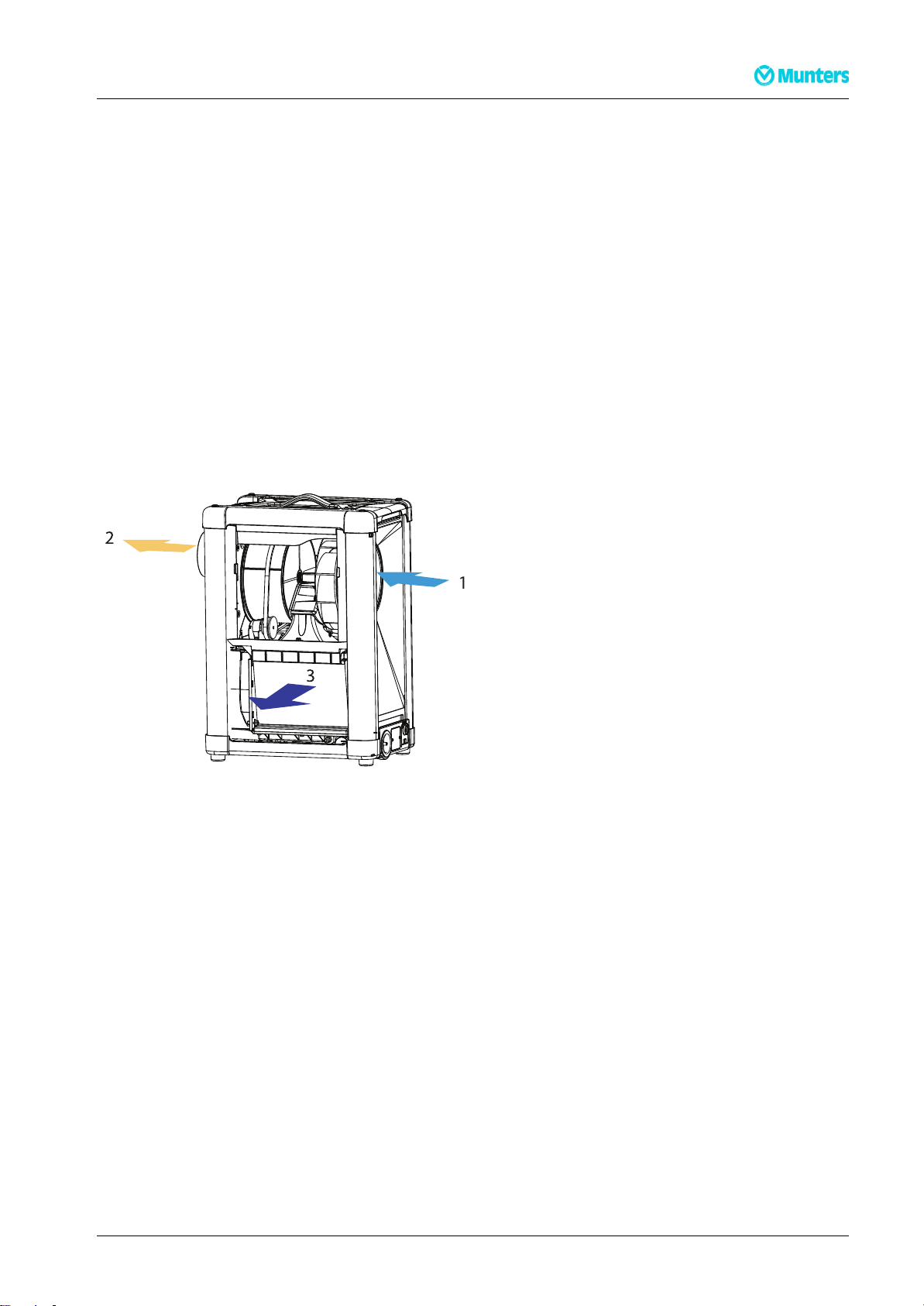
2Principleofoperation
Thedesiccantrotoristheadsorptiondehumidifyingcomponentintheunit.Therotorstructureis
comprisedofalargenumberofsmallairchannels.
Thedesiccantrotorismadeofacompositematerialthatishighlyeffectiveinattractingandretainingwater
vapour.Therotorisdividedintwozones.Theairowtobedehumidied,processair,passesthroughthe
largestzoneoftherotorandthenleavestherotorasdryair.Sincetherotorrotatesslowly,theincomingair
alwaysmeetsadryzoneontherotor,thuscreatingacontinuousdehumidicationprocess.
Theairowthatisusedtodrytherotor,reactivationair,isheated.Thereactivationairpassesthrough
therotorintheoppositedirectiontotheprocessairandleavestherotoraswetair(warmhumidair).The
wetairre-circulatesthroughacondenserthatcoolsdowntheairtocondensethewaterusingapartofthe
processair.
Thecondensedwaterisdischargedbygravitythroughahose.
Thisprincipleenablesthedehumidiertoworkeffectively,evenatlowtemperaturesfrom±0°C.
Figure2.1Principleofoperation
1.Processair
2.Dryair
3.Coolingairout
190TEN-1098-D1404Principleofoperation4
Page 8
ComDryM160L
3Transport,inspectionandstorage
3.1Transport
Beforemovingthedehumidier,makesurethereisnowaterleftinthedrainbypullingthedrainplugout.
CA
UTION!
CA CA
UTION! UTION!
Removethedrainpipefromthetraytoavoiddamage,seesection4.5,Installationoftheunit.
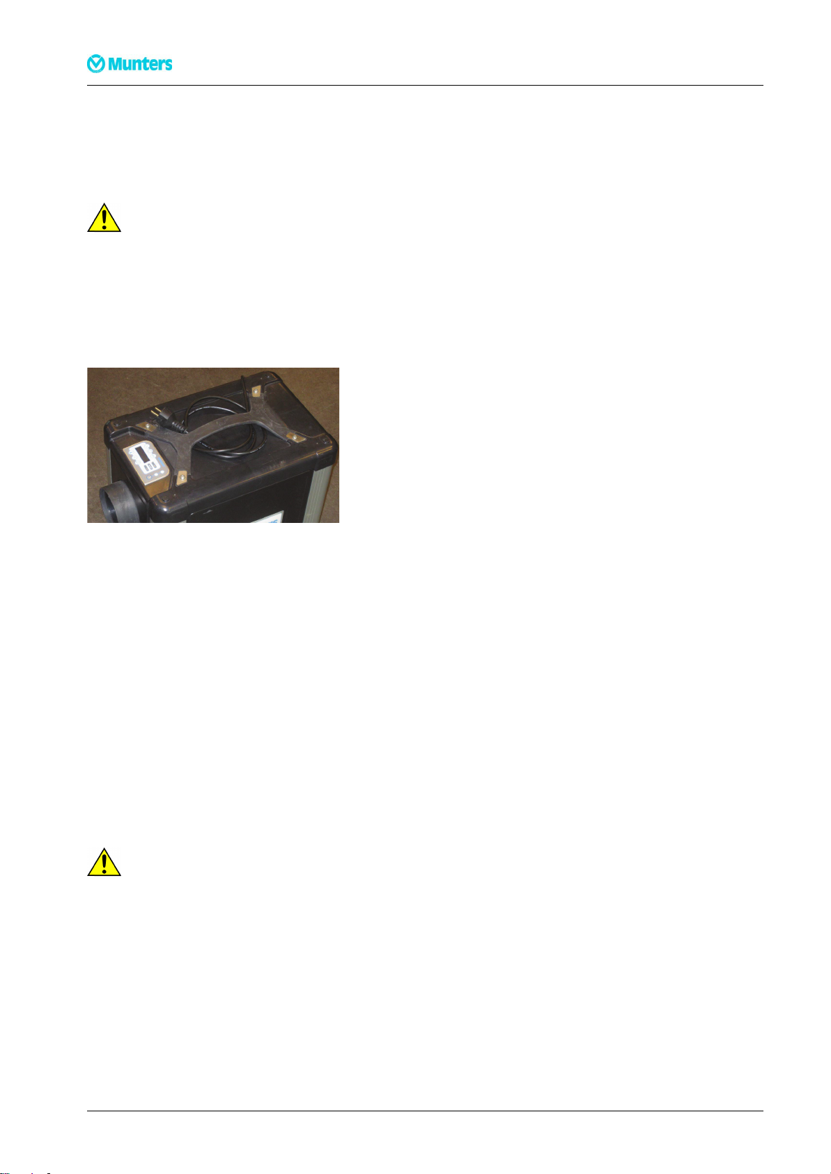
Transportthedehumidierbycarryingitbyitshandleorintheoriginalpackaging.Theunitmustalwaysbe
placedinanuprightpositionduringtransport.Failuretocomplywiththiscancausetheunittomalfunction.
Thepowercordshouldberolledupandplacedunderthehandlewhencarryingthedehumidier,see
Figure3.1.
Figure3.1Powercordplacement
3.2Inspectionofdelivery
1.Inspectthedeliveryandcomparewiththedeliverynote,orderconrmationorotherdelivery
documentation.Makesurethateverythingisincludedandnothingisdamaged.
2.ContactMuntersimmediatelyifthedeliveryisnotcompleteinordertoavoidinstallationdelays.
3.Iftheunitistobeputintostoragepriortoinstallation,seesectionStoringtheequipment.
4.Removeallpackagingmaterialfromtheunit,andmakesurethatnodamagehasoccurredduring
transportation.
5.AnyvisibledamagemustbereportedinwritingtoMunterswithin5daysandpriortoinstallationof
theunit.
6.Disposeofthepackagingmaterialaccordingtolocalregulations.
3.3Storingtheequipment
CA
UTION!
CA CA
UTION! UTION!
Alwaysunplugtheunitfromthepowersupplywhennotinuse.
Followtheseinstructionsifthedehumidieristobestoredpriortoinstallation:
■Placethedehumidierinanuprightpositiononahorizontalsurface.
■Re-usethepackagingmaterialtoprovideprotectionfortheunit.
■Protectthedehumidierfromphysicaldamage.
■Storethedehumidierundercoverandprotectitfromdust,frost,rainandaggressivecontaminants.
5Transport,inspectionandstorage190TEN-1098-D1404
Page 9
ComDryM160L
1
2
Com Dry M160L
3
4Installation
4.1Safety
W
ARNING!
W W
ARNING! ARNING!
Donotconnecttheunittoothermainsvoltagethanspeciedontheidenticationplate.
Theunitmustbeconnectedtoanearthedelectricaloutlet.
Donotoperatetheunitifthepowerplugorcordisdamaged.
CA
UTION!
CA CA
UTION! UTION!
Donotsit,stand,orplaceanyobjectsontheunit.
NOTE!Whenadehumidierisplacedinabuildingwithradonitisnecessarytocontactanexperttosecurethe
bestoverallsolution.Allchangesaffectingtheventilationorthepressurebalanceinthebuildingcanresultina
changedconcentrationofradon.
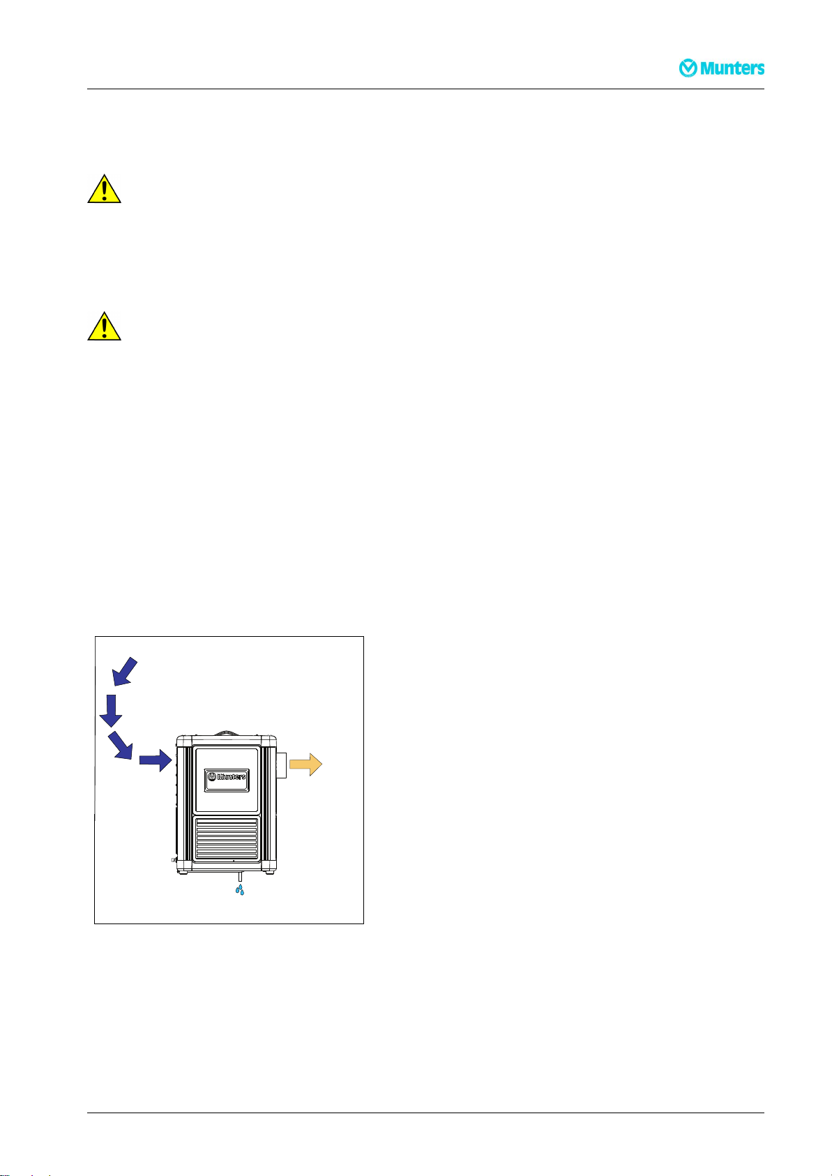
4.2Closedsystem
Thedehumidierisplacedinthespacetobedehumidied.T oensurethatthedryairisdistributedevenly
inthespacetobedehumidiedaductingcanbeconnectedtothedryairoutletofthedehumidier.The
condensedwaterisdrainedthroughahose.
Aclosedsystemispreferablewhenthereisaneedfordehumidicationtoaverydryclimate.Itismore
economicaltoruncomparedtoanopensystem.
1.Process/Reactivationair
2.Dryair
3.Condensedwater
Figure4.1Closedsystemprinciple
190TEN-1098-D1404Installation6
Page 10
ComDryM160L
2
1
3
Com Dry M160L
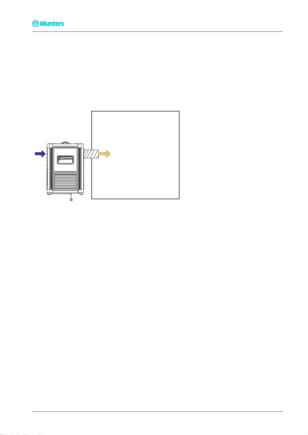
4.3Opensystem
Thedehumidierisplacedoutsidetheareatobedehumidied.Dryairistransportedwithductingtothe
spacetobedehumidied.Thecondensedwaterisdrainedthroughahose.Theinstallationisusedtosolve
thefollowingproblems:
-Whenmoisturedamagedobjectsaretobedehumidied.
-Dustorcorrosioncausingparticlesarepresentinaspacewheredryairwillbesupplied.
-Topreventmoisturefromenteringthedehumidiedspace/object.
1.Process/Reactivationair
2.DryAir
3.Condensedwater
Figure4.2,Opensystemprinciple
4.4Siterequirements
Thedehumidierisonlyintendedforindoorinstallation.Avoidinstallingthedehumidierinadamp
environmentwherethereisariskofwaterenteringtheunitorinaverydustyenvironment.Ifindoubt,
seekadvicefromMunters.Itisimportantthattheintendedinstallationsitemeetsthelocationandspace
requirementsfortheequipmentinordertoachievethebestpossibleperformanceandtrouble-free
operation.Forspacerequirements,seesection10.1,Dimensionsandservicespace.
7Installation190TEN-1098-D1404
Page 11

ComDryM160L
1
2
4.5Installationoftheunit
ComDryM160Lisdesignedtobemountedonawallusingthewallbracketincludedinthedeliveryofthe
unit.Seetheseparatewallbracketleaet.
1.Assemblethethreemainpartsofthewallbracket.Seeitem1,2and3intheleaet.Usethefourscrews
included.
2.Markfourwallholesusingtheencloseddrillpattern.Makesuretogetatleast25cmspacebetweenthe
dehumidierandtheoor.
3.Usefourscrewswithamaximumdiameterof7mm(notincluded)tomountthebracketonthewall.
4.Screwthewallbracketontothewall.
5.Laydownthedehumidier.
Figure4.3Figure4.4
6.InserttheO-ring(1)intothedrainpipesleeve(2).PresstheO-ringsoitisproperlyseatedinthegroove
seeFigure4.3
7.Pushthedrainpipeontothedrainconnectionofthetray,seeFigure4.4
8.Fastenthedrainpipewiththetwoenclosedscrews.
9.Therearetwoslotsintheshelfenablingalashingstraptobemountedifthedehumidieristobexed
byastrap.
10.Alternativelythefourfeetcanbelockedsimplybychangingthescrewineachfoottoalonger(not
included)andusethefourpre-drilledholesinthebracket.Fournewwasherswillalsobeneeded.
11.Finallyputthehoseontothedrainpipeandlockthehoseusingahoseclamp.
12.Ifductsorhosesaretobeinstalled,seesection4.6,Ductsandhoses.
190TEN-1098-D1404Installation8
Page 12
ComDryM160L
4.6Ductsandhoses
Wheninstallingductworkbetweenthedehumidierandtheinletandoutletconnections,thefollowing
recommendationsshouldbeobserved:
■Ductlengthmustbekeptasshortaspossibletominimisestaticpressureloss.
■Allductandhoseconnectionsmustbeairtightandvapourtighttoensurefullperformance.
■Thetotalresistanceintheductworkmustnotexceedtheperformanceratingofthefansttedinthe
dehumidier.
NOTE!Maximumlengthofdryairhoseis25metres.
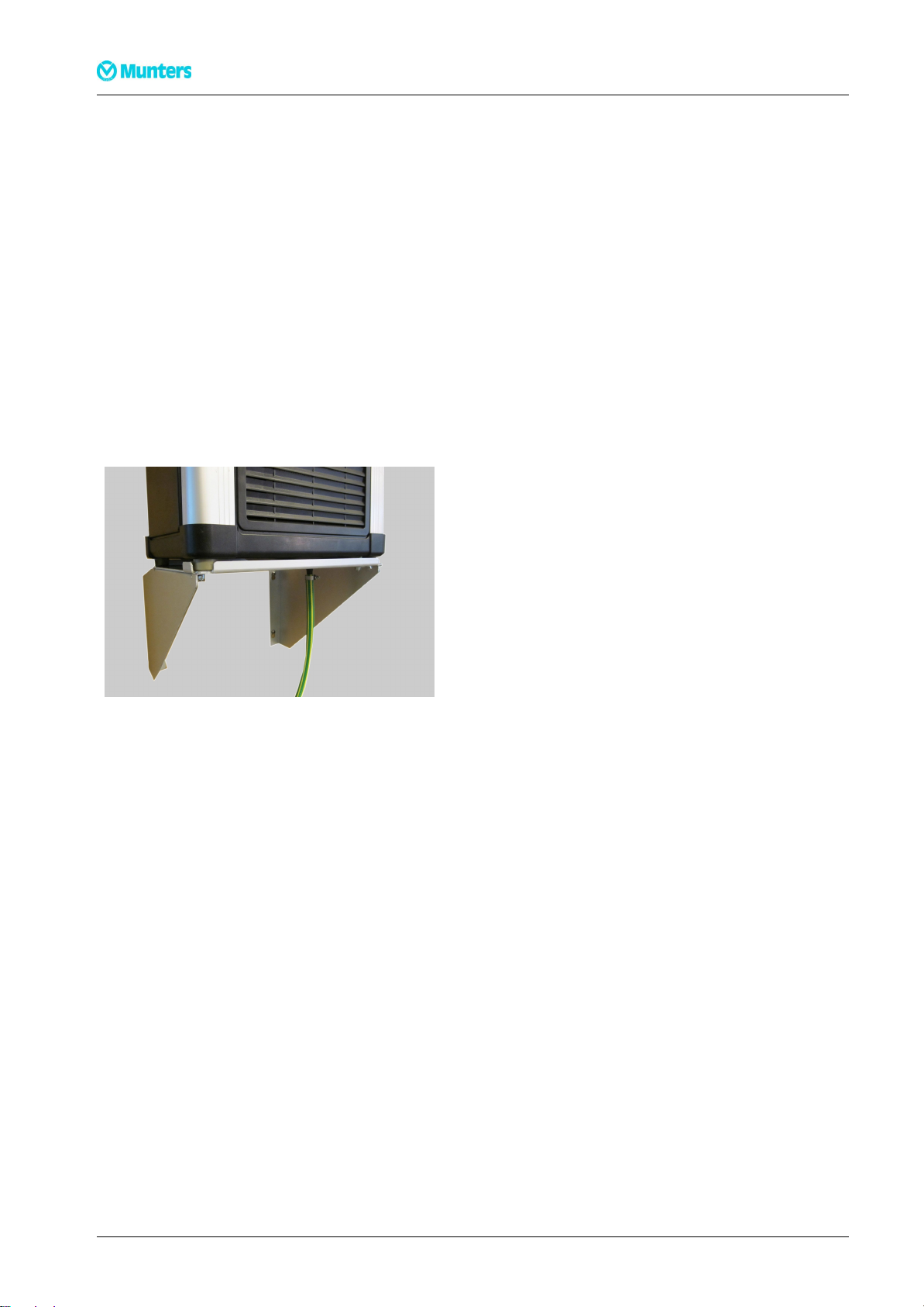
4.7Connectingthedrainhose
Beforeconnectingthedrainhosethedehumidiermustbemountedonthewallusingtheenclosedwall
bracket.Theminimumdistancebetweenthebottomofthedehumidierandtheooris25cm.
Figure4.5Drainhoseconnection
9Installation190TEN-1098-D1404
Page 13

ComDryM160L
4.8Electricalconnections
Thedehumidierisdeliveredwitha2,7metrepowercable,equippedwithanearthedplug.Themain
electricalcomponentsareinstalledintheupperpartoftheunit.
CA
UTION!
CA CA
UTION! UTION!
Donotconnecttheunittoothermainsvoltagethanspeciedontheunit’sidenticationplate.
Themainsfrequencycanbeadjusted,seeTable7.5.
NOTE!Incaseofaxedinstallationwheretheplugisreplacedbyacircuitbreaker,checkthatthefuserating
inthecircuitbreakeriscorrect.
190TEN-1098-D1404Installation10
Page 14

ComDryM160L
4.9Expandingthesystem
CA
UTION!
CA CA
UTION! UTION!
NeverconnectComDrydirectlytoastandardEthernetnetwork,eveniftheconnectortypeisthesame(RJ45-8,
modularconnector).DoingsomightdamageboththeComDrycontrolsystemand/orthecomputernetwork.
AllComDrydehumidiersareequippedwithtwoCANBUSports,locatedbehindacovernexttothe
applianceinlet.Anindoorremotecontrol,externalhumidity/temperaturesensorsoranexternalsignalbox
canbeconnectedtotheseCANBUSports.Itdoesnotmatterwhichoftheabovedeviceswillbeconnected
towhichport.Whennoportisusedthetwoemptyterminationplugsmustbettedtotheports.
Figure4.6RemovethecoverFigure4.7,2CANBUSportswithemptyplugstted
11Installation190TEN-1098-D1404
Page 15

ComDryM160L
kWh
C
f
X
4.10Accessories
Therearesomeaccessoriesavailableasoptionstothedehumidier.
WallBracket.Astheunitmustbemountedonthewallthisisincludedinthesupply .
StubPipeKitisusedwhenthereisaneedtoconnectaninletductorhosetothedehumidier.
RemoteControlmakesitpossibletocontroltheunitfromdistance,deliveredwitha10metrecable.
Externalsignalboxisusedwhenthereisaneedtoconnecttoanexternalcontrolsystem.
RemoteRH/Tsensorforexternalmeasuringofhumidityandtemperature.
WallBracket
StubPipeKit
RemoteControl
Externalsignalbox
RemoteRH/Tsensor
190TEN-1098-D1404Installation12
Page 16

5Controlpaneloverview
C
f
X
kWh
1
2
3
4
5
6
A
B
C
RH1 55%
*
ComDryM160L
Menuindicators1-6
1.Humiditymenu4.T emperaturemenuA.Alarmindicator
2.Timemenu5.FunctionsmenuB.Operationindicator
3.Powermenu6.AlarmmenuC.On/Offbutton
MenubuttonFunction
Table5.1Menubuttonfunctions
Up/Rightbutton
Enter/Conrmationbutton
Down/Leftbutton
13Controlpaneloverview190TEN-1098-D1404
Page 17

ComDryM160L
6Operation
6.1Safety
W
ARNING!
W W
ARNING! ARNING!
Donotoperatetheunitifthepowerplugorcordisdamaged.
Donotinsertngersoranyotherobjectsintotheairvents.
Theunitcanrestartautomaticallywithoutwarningfollowingapowerfailure.
CA
UTION!
CA CA
UTION! UTION!
Donotsit,stand,orplaceanyobjectsontheunit.
6.2Introduction
6.2.1Humiditycontrol
TheComDrydehumidierisequippedwithasophisticatedmicroprocessorbasedcontrolsystem.This,in
combinationwiththebuilt-inhumidity/temperaturesensorintheprocessairinlet,makesitpossibletoset
boththecontrolandpresentationofthehumiditytoeitherrelativehumidity(RH%),dewpoint(Dp°C)or
absolutehumidity(Xgr/kg).Thecontrolsystemadditionallychecksthetemperaturesbeforeandafterthe
heater,aswellasinthewetairaftertherotor.Ahighsafetylevelisobtainedbyvarioustemperaturesensors.
Toohightemperaturesgivesareductionoftheheaterpower,whileexcessivetemperatureswillmakethe
systemissueanalarmandshutthedehumidierdowninacontrolledway.Forfurtherexplanation,see
7.1,Humidityand7.5,Functions.
NOTE!Thedehumidieralwaysoperatesinautomaticmode(moisturebasedoperation).Asdefaultitwilluse
thebuilt-inhumidity/temperaturesensor,asoptionanexternalsensor.
6.2.2Fanmodes
Dependingontheapplication,ifxedortemporarilyinstalledetc.,thedehumidiercanberunindifferent
processfanmodes:Fan“ON”(continuous),“INT”(INTermittent)or“DEM”(onDEMand).Forfurther
explanation,see7.5,Functions.
6.2.3Fanspeed
Therearethreeprocessfanspeedsettingsavailable:“HIGH”,“NORM”and“LOW”.Thespeedis
manuallysetbytheoperator.Forfurtherexplanation,see7.5,Functions.
190TEN-1098-D1404Operation14
Page 18

ComDryM160L
C
B
B
6.3Initiationandstart
6.3.1Bootthecontrolsystem
Connectthedehumidiertomains.Result:ThecontrolsystemwillinitiatebyashingallLEDsforafew
seconds,andthedisplayrstshowstheComDrymachinetype[[M160L],thenthesetfrequency ,e.g.[50Hz]
andnallythesoftwareversionnumber,e.g.[VER:1.00]andthecurrenthumiditylevel,e.g.[*RH146%].
NOTE!Thebootsequencetakesabout10seconds.Letthecontrolsystemnishthebootingbeforeattempting
tostartthedehumidier.
6.3.2Startthedehumidier
Followthesestepstostartthedehumidier:
StepActionIllustration
1PresstheOn/Offbutton(C)oncetostartthedehumidier.
Result:IfthemeasuredhumidityislowerthantheSetValue,
thegreenoperatingindicator(B)willstarttoashinalong
on/shortoffsequence.Dependingonfanmodesetting,the
processfanwillrunornot.Theunitisnowinstand-bymode.
2Thedehumidierstartstodehumidifywhenthemeasured
humidityisequalorgreaterthantheSetV alue,andthe
operatingindicator(B)willshifttocontinuouslylit.
15Operation190TEN-1098-D1404
Page 19

ComDryM160L
6.4Stopthedehumidier
CA
UTION!
CA CA
UTION! UTION!
Donotunplugthedehumidierwhileitiscoolingdown.Ifunpluggeditmightleadtopermanentunitdamage.
Followthesestepstostopthedehumidier:
Step
1
2
Action
PressOn/Offoncetostopthedehumidier.Thegreenoperatingindicatorstartsashing
Theunitcontinuestorunforawhileinordertocooldownand
thenstops.
Result/Illustration
withequallylongandshortonandoffperiods.
6.5Emergency
CA
UTION!
CA CA
UTION! UTION!
Onlyquickstopthedehumidierinthecaseofanemergency.Thefanstopsandtheheatercanbeveryhot,which
canresultindamagetotheheaterandothercomponentsclosetoit.
Incaseofemergency,stopthedehumidierbypullingthemainsplugor,ifitispermanentlyconnected
tomains,byusingtheexternalswitch.
6.6Automaticstartafterpowerfailure
Ifthedehumidierisswitchedonitwillreverttooperationafterapowerfailure,regardlessofifitwas
runningorinstand-by .
190TEN-1098-D1404Operation16
Page 20

ComDryM160L
f
X
6.7Navigatethemenus
Thethreebuttons,andonthecontrolpanelmakeitpossibletonavigatethemenus.
Followthesestepstonavigatethemenus:
Step
Action
1
Toselectamenu,pressor.untiltheselectedmenuappears.
2
Toenterthemenu,press.
3
Useortoscrollthroughthemenu.
4
Leavethemenubyusingandgoto[EXIT].
Press.
NOTE!Allmenulistsarecircular.Attheendofeachmenuyouwillnd
thereistopress
onetimeafterhavingenteredamenu.
[
EXIT
Result/Illustration
Theselectedmenuindicatorislit.
Themenuindicatorstarts
ashing.
Themenuindicatorstops
ashing.
]
.Thequickestwayofnavigating
17Operation190TEN-1098-D1404
Page 21

ComDryM160L
f
X
C
f
X
kWh
f
X
ACCE S S
f
X
6.8Accessthecontrolsystem
Thecontrolsystemsettingsandcountersareprotectedagainstunauthorizedchangeusingtwoaccesslevels.
Seealsosection6.14,Accesslevels.
Followthesestepstoaccessthesystem:
StepActionResult/Illustration
1T ochangethesettingsyoumusthave“one-star”access.Gotomenu
Functions,seesection6.7,Navigatethemenus.
2
Scrollupto[ACCESS]using.
3
Pressandholduntil[ACCESS]changesto[ACCESS*].
4Ahigher ,PIN-codeprotected,“two-star”accesslevelexists.Ifanattempt
togethigheraccessismadewiththemachineswitchedoff,thedisplaywill
changeto[0000].
Press
fourtimesuntil[ACCESS*]isvisibleagain.
Themenuindicatorisashing.
Thesystemisnowunlocked,
anditispossibletomakenew
settingsalternativelyresetthe
counters.
NOTE!Thesystemwillreturntolockedmodeautomaticallyafterveminuteswithoutanyactivity.
NOTE!Thesystemalwaysstartsinlockedmodeafterpower-up(orpowerfailure),regardlessofaccesslevel
priortounpluggingtheunit.
Followthesestepstoforcethesystemintolockedmode:
StepActionResult/Illustration
1Makesuretheunitisswitchedoff.
2Gotomenu"Functions"
3Navigateto[ACCESS*].Seegeneral
instructioninsection6.7,Navigatethemenus.
4StarttheunitbypressingOn/Off.Thegreenlightilluminates
5Pressandhold
until[ACCESS*]changesto[ACCESS].
Thesystemisnowlocked,anditisnotpossibletomakenew
settingsortoresetthecounters.
190TEN-1098-D1404Operation18
Page 22

6.9Changethesystemsettings
Tochangesettingsyoumusthave“one-star”access,see6.8,Accessthecontrolsystem.
Followthesestepstochangethesystemsettings:
ComDryM160L
Step
Action
1
Navigatetotheparameteryouwanttochangebyusingor.
2
Press.
3
Changethevaluewithand.
4
Conrmthenewsettingwith.
Result/Illustration
Thesettingstartstoash.
Thesettingstopstoash.
NOTE!Ifthenewsettingisnotconrmedwithin30seconds,thedisplaychangesbacktotheoldsetting.
NOTE!Read-onlyvaluesarenotchangeable.Theywillnotstarttoashif
level.Tondoutifaparameterischangeableorread-only,seesection7,Menusandparameters.
ispressed,regardlessofaccess
19Operation190TEN-1098-D1404
Page 23

ComDryM160L
C
f
X
kWh
f
X
Rs t
NO
6.10Resetanalarm
Followthesestepstoresetanalarm:
StepActionResult/Illustration
1Writedownthealarmmessagebeforeresettingthealarm.The
informationmightbehelpfulwhentroubleshooting.
2Waituntilthedehumidierhasstopped.
Press.
3
Toggle[NO]to[YES]bypressingeitheror.
Conrmbypressing
.
Thedisplaychangesto[RstNO]and[NO]
isashing.
Whenthealarmhasbeenreset,themenu
systemreturnstoitsstartposition.
NOTE!Ifthecauseofanalarmisstillpresent,thealarmmightbere-issuedafterresetting,evenifthe
dehumidierisstopped.
190TEN-1098-D1404Operation20
Page 24

6.11Resetthecounters
C
f
X
kWh
f
X
Rs t
NO
Toresetcountersyoumusthave“one-star”access,see6.8,Accessthecontrolsystem.
Followthesestepstoresetthecounters:
ComDryM160L
Step
Action
1
Navigatetothecounteryouwanttoreset.Seesection
6.7,Navigatethemenus.
2
Press
3
Toggle[NO]to[YES]bypressingeitheror.
NOTE!If
[
RstNO
]/[
RstYES
seconds,thedisplayautomaticallychangesbacktothestored
countervalue.
4
Conrmtheresettingwith
NOTE!PressingENTERwhenthedisplayshows
again.
]
isleftwithoutactionfor30
.
Result/Illustration
Thedisplaychangesto
[RstNO]and[NO]isashing.
Thecounterisreset.
[
RstNO
]
willreturnthestoredcountervalueinthedisplay
21Operation190TEN-1098-D1404
Page 25

ComDryM160L
6.12Serviceintervalalarm
TheServiceinterval[T-xxxxh]issettablebetween500and8.000hours.Seealsosection
8.2,Maintenanceschedule.
Toresetcountersyoumusthave“one-star”access.Followthesestepstochangetheserviceinterval(see
also6.9,Changethesystemsettings):
Step
Action
1
GototheTimemenu.
2
Navigateto"Serviceinterval"[T-xxxxh]
2
Adjustthe"Serviceinterval"[T-xxxxh]instepsof100hours
3
Resetthe"Timetoservice"counter[Sxxxxh].
Result/Illustration
NOTE!The"Timetoservice"countercanberesetatanytime.Whenthecounterisreset,itstartscountingupor
downagainfromthepre-setvalue[T-xxxxh]dependingonhowthe"Serviceinterval"hasbeenadjusted.
TheTimetoservicecounter[Sxxxxh]countsdowntozero.Whenitreacheszero,thesystemissuesa"soft
alarm"thenexttimetheunitisswitchedon.Thealarmonlymakesthealarmmenusymbolash,notthe
redalarmindicator,and[TIMEFORSERVICE]isshowninthedisplay.Thealarmwillnotmaketheunit
stop.Theunitcanstillbeoperatedasnormalwiththealarmpresent.
Followthesestepstochecktheserviceparametersandstoptheservicealarm:
Step
Action
1Toseeorcheckparameters,eitherresetthealarmbypressing
andresetit,orleavetheAlarmmenuwith[EXIT].
2
Tostopthealarmcompletely ,navigatetothe"Timetoservice"counter[S
0000]inthismenuandresetit.
Result/Illustration
NOTE!EvenifthealarmhasbeenresetintheAlarmmenu,itwillbere-issuedthenexttimetheunitisswitched
on.
See8.2,Maintenancescheduleforpropermaintenanceaction.
190TEN-1098-D1404Operation22
Page 26

ComDryM160L
C
f
X
kWh
f
X
Rs t
NO
6.13Restorethedefaultsettings
Torestorethefactorydefaultsettingsyoumusthave“one-star”access,see6.8,Accessthecontrolsystem.
Followthesestepstorestoreallthedefaultfactorysettings:
Step
Action
1
GototheFunctionsmenuandnavigatetoDefault.
2
Press
3
Toggle[NO]to[YES]bypressing
eitheror
4
Conrmbypressing.
6.14Accesslevels
Thefollowingaccesslevelsandactionsareavailableinthecontrolsystem:
AccesslevelAvailableactions
ACCESS
ACCESS*
ACCESS**
Viewallprocessingdata
■Viewallprocessingdata
■Adjustrelevantparameters(fanspeed,set
valueRH,resethorkWhetc.)
Result/Illustration
Thedisplaychangesto[RstNO]and[NO]isashing.
Allvaluesrevertstofactorysettings.
Comment
■Level2isfordedicatedpersonnelonly
(qualiedpersonnelorMuntersService)
■Ifyouhaveaccidentallyreachedthislevelthe
codeis0000forreturningtolevel1.
23Operation190TEN-1098-D1404
Page 27

ComDryM160L
C
f
X
kWh
f
X
*RH1 49%
C
f
X
kWh
f
X
RH2 35 %
C
f
X
kWh
f
X
RH3 35 %
C
f
X
kWh
f
X
S V RH 5
7Menusandparameters
Tosetthesystemparameters,see6.9,Changethesystemsettingsand6.11,Resetthecounters.Forlimitswhen
settingparameters,see7.7,Min,maxanddefaultvalues.
7.1Humidity
Thedehumidierisalwaysoperatinginautomaticmode.Itwilldehumidifyuntilthedesiredhumiditylevel
(SetValueminusHysteresisvalue)isreached.Thenthegreenoperatingindicatorwillstarttoashinalong
onandshortoffsequence,indicatingthatthedehumidierisinstand-by.Itwillstarttodehumidifyagain
whenthehumidityisequalto,orgreaterthantheSetValue.
Typeofhumiditycontrol(relativehumidity,dewpointorabsolutehumidity)andunitsystem(metricor
imperial)governsthereadingsandsettingsinthismenu.See7.5,Functionsforreferenceandexplanation.
ThistableshowsthedisplayviewsandpossiblesettingsoftheHumiditymenu:
Displayview
Internalsensorreading
(Externalsensorreading)
(Externalsensorreading)
DescriptionType
READONLYD1.../X1...
1
1
READONLYD2.../X2...
READONLYD3.../X3...
Settingoption
SetValueHumidityADJUSTABLEHIGHER/LOWER
190TEN-1098-D1404Menusandparameters24
Page 28

ComDryM160L
C
f
X
kWh
f
X
HYS 2%
C
f
X
kWh
f
X
RH1
*
Displayview
1)
Onlywhenexternalhumiditysensorsareconnected
Table7.1Humiditymenu
7.1.1Internalcontrollingsensor
DescriptionType
Hysteresis
Controllingsensor(ADJUSTABLE)
ADJUSTABLEHIGHER/LOWER
Settingoption
1
1
(*RH2)
1
,(*RH3)
Theinternalhumiditysensoristhecontrollingsensorasdefault.Thisisindicatedbya(*)beforethereading
inthedisplay(*RH1…/*D1…/*X1…).
7.1.2Externalcontrollingsensors
Optionally,uptotwoexternalsensorscanbeconnected.Theywillautomaticallybedesignated
(RH2/D2/X2)and(RH3/D3/X3)bythesystem(numbertwobeingtherstconnectedinthechain).
Whenconnected,itispossibletochooseoneoftheexternalsensorsascontrol.Thedisplaywillthenshow
(*RH/D/X2…)or(*RH/D/X3…).
Withanexternalsensorsetascontrolsensor,itispossibletodisconnectandreconnecttheexternal
sensor/-swithoutlosingthecontrolsetting,e.g.[*RH2…]whiletheunitisswitchedoff(butpowered).
Whenswitchedon,thesystemmakesveattempts(duringapprox.20seconds)tocontacttheexternal
controllingsensor.Ifthisfails,thesystemrevertstotheinternalRH1-sensor.Subsequentlyanyrenewed
assignmentoftheexternalsensorascontrolmustbecarriedoutmanually.
25Menusandparameters190TEN-1098-D1404
Page 29

ComDryM160L
f
X
kWh
f
X
261 h
C
C
f
X
kWh
f
X
341 h
C
C
f
X
kWh
f
X
S 39 99 h
C
C
f
X
kWh
f
X
T-400 0 h
C
C
7.2Runtime
Runtimeisregisteredaslongastheprocessairfanisoperating.Itstopscountingwhentheunitisinstand
bymodeorisswitchedoff.Thesystemhastworuntimecounters,oneresettabletripmeterandone
non-resettabletotalruntimecounter.
ThistableshowsthedisplayviewsandtypeofinformationoftheTimemenu:
Displayview
DescriptionType
Runtimetripmeter
Totalruntime(Displayjumps
from“TOT AL”todisplayview
andback).
Timetoservice
Settingoption
RESETTABLEY es/No
READONLY
RESETTABLEY es/No
Table7.2Timemenu
ServiceintervalADJUSTABLE
Every100hours
190TEN-1098-D1404Menusandparameters26
Page 30

ComDryM160L
f
X
kWh
f
X
411 kWh
C
C
kWh
f
X
kWh
f
X
88 7 W
C
C
kWh
f
X
kWh
f
X
3.88 229
C
C
7.3Power
TheComDrydehumidierisequippedwithanintegrated,resettablekWhcounter.Theenergy
consumptionisregisteredwhenthedehumidierisconnectedtomains,regardlessofbeingswitchedon,off
orinstand-bymode.ThecountershowstheconsumptionaswholekW-hours.
ItisalsopossibletomonitorrealtimePower(W),current(A)andvoltage(V)measurementsinthismenu.
NOTE!Resettingisalwaysperformedmanually.Unpluggingtheunit(orapowerfailure)willnotresetthekWh
counter.
ThistableshowsthedisplayviewsandtypeofinformationofthePowermenu:
DisplayviewDescriptionType
kWhcounter
RealtimePower
RESETTABLEYes/No
READONLY
RealtimeCurrent/V oltageREADONLY
Settingoption
Table7.3Powermenu
27Menusandparameters190TEN-1098-D1404
Page 31

ComDryM160L
f
X
kWh
f
X
T1 28 C
C
C
f
X
kWh
f
X
T2 23 C
C
C
f
X
kWh
f
X
T3 23 C
C
C
f
X
kWh
f
X
Rt 121 C
C
C
7.4Temperature
Theairtemperatureismeasuredindifferentpositionsinthedehumidier.Allvaluesareread-only.
Ifexternalhumidity/temperaturesensorsareconnected,thesewillalsobefoundinthelist.Thereactivation
inlettemperature(Ri)beforetheheaterandreactivationtemperature(Rt)aftertheheater,aswellasthewet
airtemperature(Wt)andtheprocessairinlettemperature(T1)ismeasured.
NOTE!ThetemperaturewillbeshowninCelsius(metric,SI)orFahrenheit(imperial,IP),dependingontheunits
settingintheFunctionsmenu.
ThistableshowsthedisplayviewsandtypeofinformationoftheTemperaturemenu:
DisplayviewDescriptionT ype
Processairinlettemperature(internal
READONLY
sensor)
(Externalsensor)
(Externalsensor)
1
1
READONLY
READONLY
Settingoption
Reactivationtemperature
190TEN-1098-D1404Menusandparameters28
READONLY
Page 32

ComDryM160L
f
X
kWh
f
X
Wt 3 9 C
C
C
f
X
kWh
f
X
Ri 3 1 C
C
C
DisplayviewDescriptionT ype
1
)Onlyifexternalsensorisconnected
Table7.4Temperaturemenu
Wetairtemperature
Reactivationinlettemperature
Settingoption
READONLY
READONLY
29Menusandparameters190TEN-1098-D1404
Page 33

ComDryM160L
7.5Functions
7.5.1Processfanspeed
Tosetfanspeedyoumusthave“one-star”access,see6.8,Accessthecontrolsystem.Theprocessfanspeedcan
besetto[SpdHIGH],[SpdNORM]or[SpdLOW].Thecapacitiesandfancurvesinsectionandaregiven
atHIGHspeed.NORMALspeedwillreducethecapacityslightly,whileLOWspeedgivesapproximately
50%capacity .
See7.5.2,Processfanmodeforhowtosetthefanparameters.
7.5.2Processfanmode
Therearethreeprocessfanmodes:
FanmodeDescription
[FanON]In[FanON]mode,thedehumidierwillruntheprocessfancontinuously,regardlessofthereisa
dehumidicationneedornot.Thisisthedefaultmode.
[FanINT]
(INTermittent)
[FanDEM](on
DEMand)
In[FanINT](INT ermittent)mode,thefanwillstopwhenthedesiredhumidity(SetV alueminusHysteresis)
isreached.IfthehumidityreadingstaysbelowtheSetValue,theprocessfanwillanyhowstartafter30
minutestoletthebuilt-insensormoreaccuratelysensetheconditionoftheincomingprocessair.The
fanwillrunforaminutetoproduceapropermeasurement.IfthehumidityisstillbelowtheSetV alue,
thefanwillstopagain.ThisisrepeateduntilthehumidityreachestheSetV alue,whichwillmakethe
dehumidicationstartagain.
In[FanDEM](onDEMand)mode,thefanwillstopwhenthedesiredhumidity(SetValueminus
Hysteresis)isreached.Itwillstartagainwhenthesensedhumidityisequalto,orgreaterthantheSet
Value.Thisgivesinpracticeacontrolwithgreaterhysteresisthan“FanINT”,dependingonthefollowing:
Whenthedehumidierhasreachedthedesiredhumiditylevel,itwillshifttostand-byandstoptheprocess
fan.Afterawhile,internalmachineheatwillincreasethetemperatureofthehumiditysensor .Thismakes
thesensorreadingevenlower ,i.e.thesystemfunctionsasiftherewasa“negativehysteresis”.Asa
result,agreaterhumidityloadwillbenecessarytomakethedehumidierstartcomparedwiththe“Fan
INT”mode.
7.5.3Humiditycontrolandunits
Theinternalhumidity/temperaturesensor,“RH1”(locatedbehindtheprocessairlter),makesitpossible
tosetthecontrol/presentationofthehumiditytoeitherRelativehumidity(RH%),Dewpoint(Dp°C)
orabsolutehumidity(Xgr/kg).Dependingonunitsystemsetting,SIformetricorIPforImperial,the
readingswillbeshowninCelsiusandg/kg,orFahrenheitandgrain/lb.Allthesesettingsaremadeinthe
Functionsmenu.
190TEN-1098-D1404Menusandparameters30
Page 34

7.5.4Displayinformation
f
X
kWh
f
X
Spd NORM
C
C
f
X
kWh
f
X
FAN ON
C
C
f
X
kWh
f
X
S I
C
C
f
X
kWh
f
X
RH (%)
C
C
f
X
kWh
f
X
ID999 999
C
C
f
X
kWh
f
X
ACCE S S
C
C
ThistableshowsthedisplayviewsandtypeofinformationoftheFunctionsmenu:
ComDryM160L
DisplayviewDescriptionType
ProcessfanspeedADJUSTABLESpdHIGH,NORM,LOW
ProcessfanrunningmodesADJUSTABLEFanON,INT ,DEM
Metricorimperialunits
ADJUSTABLESI,IP
Settingoption
Humidity
Unitserialno
ADJUSTABLE
READONLY
RH,Dp,Absolutehumidity
IDno
ACCESSLevelADJUSTABLEACCESS*
31Menusandparameters190TEN-1098-D1404
Page 35

ComDryM160L
f
X
kWh
f
X
De fault
C
C
f
X
kWh
f
X
50Hz
C
C
Table7.5Functionsmenu
DisplayviewDescriptionType
Restoretodefaultsettings
RESETTABLE
(onlypossiblewhen
dehumidierisOFF).
MainsfrequencyADJUSTABLE
Settingoption
YesorNo
50or60Hz
190TEN-1098-D1404Menusandparameters32
Page 36

ComDryM160L
f
X
kWh
f
X
HEATER
C
C
f
X
kWh
f
X
No Ala rm
C
C
7.6Alarm
Shouldanoperationfaultoccur,theredalarmindicatorandthealarmmenuindicatorwillstarttoash.
Thecauseofthealarmwillbeshowninthedisplayandthedehumidierwillstopafterithascooleddown,
whichmighttakeacoupleofminutes.
CA
UTION!
CA CA
UTION! UTION!
Donotunplugthedehumidierwhileitiscoolingdown–theunderlyingreasonforthealarmmightbeoverheating.
ThistableshowsthedisplayviewsandtypeofinformationoftheAlarmmenu:
DisplayviewDescriptionType
SourceofalarminfulltextRESETTABLE
Table7.6Alarmmenu
Alarmstatus
READONLY
33Menusandparameters190TEN-1098-D1404
Page 37

ComDryM160L
7.7Min,maxanddefaultvalues
7.7.1Humidity
Thistableshowstheminimum,maximumanddefaulthumidityvalues:
Parameter
SV_RH50%
(setvalue)
(hysteresis)
Max.95404099300
Default
Min.
Max.10101,01010
HYS2%
Default
Min.000,000
RH(%)Dp(°C)X(gr/kg)Dp(°F)X(grain/lb)
5097,34951
5
220,222
-300,5-202
Table7.7Minimum,maximumanddefaulthumidityvalues
7.7.2Servicetime
Thistableshowstheminimum,maximumanddefaultservicetimevalues:
Parameter
T-4000h(servicetime)
Defaultsetting
40008000500
Table7.8Time,min/maxanddefaultservicetimevalues
7.7.3Functions
Max.Min.
ThistableshowsthedefaultsettingsandsettingoptionsoftheFunctionsmenu:
Parameter
SpdNORMSpdNORMSpdHIGH,SpdLOW
FanONFanON
SI(unit)SI(metricunits)IP(imperialunits)
RH(%)RH(%)
DefaultsettingOptions
Table7.9DefaultsettingsandsettingoptionsoftheFunctionsmenu
FanINT ,FanDEM
Dp(°C/°F)
X(gr/kg)/(grain/lb)
190TEN-1098-D1404Menusandparameters34
Page 38

ComDryM160L
8Serviceandmaintenance
8.1General
W
ARNING!
W W
ARNING! ARNING!
-Donotattempttorepair,dismantleormodifythisunit.
-Removethemainsplugfromthesocketbeforestartinganymaintenancework.
Thedehumidierisdesignedforcontinuoususeoveralongperiodoftimewithaminimalamountof
supervision.Undernormaloperatingconditions,maintenancerequirementsareminimal.Theservice
intervaldependsmainlyontheoperationalconditionsandworkingenvironment.
NOTE!ItisrecommendedtocontactMuntersforserviceorrepair.Operatingfaultscanoccuriftheunitis
maintainedinsufcientlyorincorrectly.
MuntersServicecanofferaserviceplanadaptedtosuittheconditionsofaspecicinstallation.Seecontact
addressesonthebackpageofthismanual.
8.2Maintenanceschedule
Muntersrecommendsthefollowingmaintenanceschedule.Theschedulecontainsinspectionand
maintenanceproceduresaswellastherecommendedintervalsforunitsusedundernormaloperatingand
environmentalconditions.Iftheprocessaircontainsalotofdust,preventativemaintenanceshouldbe
performedatshorterintervalsthanthosespeciedbelow.
Component
ProcesslterCleantheltercartridge.Cleanthelterhousing
Unitcasing
HumiditysensorNocorrectiveactionorcheck.
Functionalityandperformance
check
andreplacethelterifnecessary.
Checkforphysicaldamageandcleanthe
outsideoftheunitasnecessary.
Nocorrectiveactionorcheck.
4000hours/6months8000hours/12months
Inspection/maintenance
Cleanthelterhousingandreplacethelter.
Checkforphysicaldamageandcleanthe
outsideoftheunitasnecessary.Checkany
lineconnectionstoensuretheyareproperly
attachedandthatthereisnoairleakage.
Checkthesensorfunctionandreplaceas
necessary.
Performacompletefunctionalityand
performancecheck,andreplacewornpartsas
necessary.
Table8.1Maintenanceschedule
35Serviceandmaintenance190TEN-1098-D1404
Page 39

ComDryM160L
8.3Processairlterchange
1.Pushthelterframedown.
2.Pullthelterholderoutwardsandremoveitfromthe
unit.
Figure8.1
3.Removetheoldlter.
4.Replaceitwithanewlter.
Figure8.2
Figure8.3
190TEN-1098-D1404Serviceandmaintenance36
Page 40

ComDryM160L
9Faulttracing
W
ARNING!
W W
ARNING! ARNING!
Theunitmustnotbeopenedbyanyoneotherthantrainedandqualiedpersonnel,duetotheriskofelectrical
shock.
Thischapterisintendedtofacilitatebasictroubleshootingandtoprovideinstructionsforcorrectiveactions.
Gothroughthetroubleshootinglistbelow .ContactMuntersiftheproblemcannotberectied.
SymptomIndication/Alarmmessage
Unithasstopped
Nodisplaytext
GreenLEDisashing:
longon,shortoff
sequence
Alarmmessage:
[SENSORFAILURE]
Alarmmessage:
[HEATERFAILURE]or
[HIGHRiTEMP]or
[HIGHRtTEMP]
Alarmmessage:
[HIGHWtTEMP]
Alarmmessage:
[DRAINFAILURE]
PossiblecauseAction
Powersupplyfault.Checkpowersupplytotheunit.
BlownfuseReplacethefuse.Forcorrecttypeandrating,seelabel
Thereisnoneedfor
dehumidication.Measured
humidityisbelowtheset
point
(modeFan"DEM"or"INT").
Brokensensor
-Overtemperature
protectionfusemighthave
tripped
-Blockedlter ,hoseorduct
-Blockedimpeller
SetValueRHistoolowindry
environment
RotordrivemechanismfaultCheckrotordrivebeltanddrivemotor.
Condensatedrainhose
clogged
abovepowersupplycordconnectiontotheunit.
None.Theunitisinstand-by.Itwillstartwhenthe
measuredhumidityreachestheSetValue.
ContactMunters.
Waituntiltheunithasstopped.Thendisconnectthe
powersupply.Checkthatthelters,hosesorductsarenot
clogged.
Toresettheovertemperatureprotectionfuse,theunitmust
bedisconnectedfromthemainsandallowedtocooldown.
Ifthealarmisreissuedaftertheunithascooleddownand
thealarmhasbeenreset,contactMunters.
CheckiflowSetV alueRHisnecessary.Adjusttohigher
value.
Checkthroughthedryairoutletthattherotorrotatesat
approximatelytenrevolutionsperhour .Ifrotordoesnot
rotate,contactMunters.
Cleanorreplacethehose
KinksonthehoseMakesuretherearenokinksonthehose.Installtheunitat
Alarmmessage:
[MAINSVOLTAGELOW]
Alarmmessage:
[LONGSTOPTIME]
Alarmmessage:
[TIMEFORSERVICE]
Indication
Alarmmessage:
[NOCOM]
Unitisconnectedtothe
wrongvoltage,orproblem
withthesupply
Brokenfan
Heaterison
CANBUSemptyplugs
orexternalconnection
missing.
least25cmabovetheoorlevel.
Checkmainssupply .
ContactMunters.
SeesectionServiceintervalalarm.
Reinstallplugsorconnectioncable.Ifalarmremains,
contactMunters.
37Faulttracing190TEN-1098-D1404
Page 41

ComDryM160L
SymptomIndication/Alarmmessage
Lossof
performance.
Thedehumidier
isrunningbutis
notcontrolling
thehumidity.
Table9.1Faulttracinglist
PossiblecauseAction
Lowreactivation
temperature
LowreactivationairowCheckthelterandanyhosesorductsforleakageor
CheckthatthehumiditySetValueislowerthanthe
measuredhumidity.
blockage.Theuseofarestrictingangeincombination
withwallpipescancausetoolittlereactivationairow.
190TEN-1098-D1404Faulttracing38
Page 42

10Technicalspecication
B
A
C
F
2
1
3
ComDr y M160L
G
G
10.1Dimensionsandservicespace
ComDryM160L
Figure10.1Dimensions,ComDryM160L
1.Processairinlet
2.Dryairoutlet
3.Coolingair
Width
(A)
445mm270mm
Width
(B)
Height
(C)
555mm
Diameter
(Dryair)
100mm12.5mm350mm500mm17kg
Diameter
Drainhose
Service
space
(F)
Service
space
(G)
Weight
Table10.1Dimensionsandweight
39Technicalspecication190TEN-1098-D1404
Page 43

ComDryM160L
ComDry M160L
0
0,1
0,2
0,3
0,4
0,5
0,6
0,7
0 5 °C 10 °C 15 °C 20 °C 25 °C 30
(kg/h )
40 %
60 %
80 %
°C
3
1
2
ComD ry M160L High speed
0
20
40
60
80
100
120
140
160
180
200
220
240
B m³/h
A (Pa)
0
25
50
75 100
125
150
175
200
10.2Capacitydiagram
Figure10.2Capacitydiagram
10.3Fancurveprocessair
1.T emperature,
processair(°C)
2.RelativeHumidity,
processair(%RH)
3.Dehumidicationcapacity
(kg/h)
(moistureremoval(kg/hour))
Figure10.3Fancurve
190TEN-1098-D1404Technicalspecication40
Density1,2kg/m
A.Staticpressure(Pa)
B.Airow(m
3
3
/hour)
Page 44

10.4Technicaldata
ComDryM160L
Processair
Free-blowingair50/60Hz(m³/h)
Ratedairowat40Pa(m³/h)
Max.staticpressure50/60Hz(Pa)
Fanmotorpower(kW)
Reactivationair
Heaterpower(kW)
Factorysetreactivationtemperature(Rt)limit(°C)
Temperatureincreaseacrossheater(°C)
Fanmotorpower(kW)
Other
DriveMotorPower(W)
Soundpressurelevel,Lowspeedfree-blowingprocessfan(dBA)
Soundpressurelevel,Normalspeedfree-blowingprocessfan(dBA)
Soundpressurelevel,Highspeedfree-blowingprocessfan(dBA)
Electricalprotectionclass(casing)
Electricalprotectionclass(electricpanel)
FanMotorWindingInsulationClassClassB
DriveMotorWindingInsulationClassClassB
Rotortype
AirlterG3,articlenumber
Environmentalconditions
Operatingtemperature(°C)
Maximuminstallationaltitude,abovesealevel(m)
Transportandstoragetemperature(°C)
Totalpower,voltageandcurrentVersion
(1)
160
150
225
0,09
0,84
130
100
0,08
5
55
61
67
IP33
IP54
HPS
150-012054-001
0...+30
2000
-20...+70
Voltage(V)
Frequency(Hz)50/6050/60
Totalpower(W)
Current(A)
Fuse
(1)
Thespeciedperformanceisbasedon20°Candairdensityof1.2kg/m³.
115230
10101010
8,84,4
3AG,250VAC,10ASlow3AG,250V AC,6ASlow
Table10.2TechnicaldataM160L
41Technicalspecication190TEN-1098-D1404
Page 45

ComDryM160L
11Scrapping
Theunitmustbescrappedinaccordancewithapplicablelegalrequirementsandregulations.Contactyour
localauthorities.
Therotormaterialisnotcombustible,andshouldbedepositedlikeglassbrematerials.
Iftherotorhasbeenexposedtochemicalsthataredangeroustotheenvironmenttheriskmustbeassessed.
Thechemicalscanaccumulateintherotormaterial.Takethenecessaryprecautionstocomplywith
applicablelegalrequirementsandregulations.
W
ARNING!
W W
ARNING! ARNING!
Iftherotoristobecutinpieces,wearasuitableCEmarkedfacemaskselectedandttedinaccordancewiththe
applicablesafetystandardstoprotectfromthedust.
190TEN-1098-D1404Scrapping42
Page 46

Page 47

ComDryM160L
12ContactMunters
AUSTRIA
BELGIUM
CZECHREPUBLIC
DENMARK
FINLAND
FRANCE
GERMANY
ITAL Y
NETHERLANDS
POLAND
SPAIN
SWEDEN
SWITZERLAND
UNITEDKINGDOM
MuntersGmbH
AirTreatment
ZweigniederlassungWien
MuntersBelgiumnv
AirTreatment
MuntersCZ,organizacnislozka
AirTreatment
MuntersA/S
AirTreatment
MuntersFinlandOy
Kuivaajamyynti
MuntersFranceSAS
AirTreatment
MuntersGmbH
AirTreatment-Zentrale
MuntersItalyS.p.A
AirTreatment
MuntersV ochtbeheersingEnergieweg69
MuntersSp.zo.o.
OddzialwPolsce
AirTreatment
MuntersSpainSA
AirTreatment
MuntersEuropeAB
AirTreatment
MuntersGmbH
AirTreatment
ZweigniederlassungRümlang
MuntersLtd
AirTreatment
Eduard-Kittenberger-Gasse56,
Obj.6
A-1235Wien
Blarenberglaan21c
B-2800Mechelen
Slevacská2368/68
CZ-61500BRNO
Ryttermarken4
DK-3520Farum
Hakamäenkuja3
FI-01510V ANTAA
106,BoulevardHéloise
F-95815ArgenteuilCedex
Hans-Duncker-Str.8
D-21035Hamburg
StradaPiani2
I-18027Chiusavecchia
IM
NL-2404HEAlphena/dRijn
ul.Swietojanska55/11
81-391Gdynia
EuropaEpresarial.EdicioLondres.
C/PlayadeLiencres2.
28230LasMatas.Madrid
POBox1150
S-16426Kista
Glattalstr.501
CH-8153Rümlang
PathnderPlace10RamsayCourt
HinchingbrookeBusinessPark
HuntingdonPE296FYCambs
Tel:+4316164298–9251
luftentfeuchtung@munters.at
www.munters.at
Tel:+321528561 1
service@muntersbelgium.be
www.muntersbelgium.be
Tel:+420775569657
info@munters-odvlhcovani.cz
www.munters-odvlhcovani.cz
Tel:+4544953355
info@munters.dk
www.munters.dk
Tel:+358207768230
laitemyynti@munters.
www.munters.
Tel:+331341 15757
dh@munters.fr
www.munters.fr
Tel:+49(0)40879690-0
mgd@munters.de
www.munters.de
Tel:+390183521377
marketing@munters.it
www.munters.it
Tel:+31172433231
vochtbeheersing@munters.nl
www.munters.nl
Tel.:+48583053517
dh@munters.pl
www.munters.com.pl
Tel:+34916400902
marketing@munters.es
www.munters.es
Tel:+4686266300
avfuktning@munters.se
www.munters.se
Tel:+41523438886
info.dh@munters.ch
www.munters.ch
Tel:+441480432243
info@munters.co.uk
www.munters.co.uk
AUSTRALIA
BRAZIL
CANADA
CHINA
INDIA
JAPAN
KOREA
190TEN-1098-D1404ContactMunters44
Tel:+61288431588
dh.info@munters.com.au
Tel:+551150540150
www.munters.com.br
Tel:+1-800-843-5360
dhinfo@munters.com
Tel:+861080418000
marketing@munters.cn
Tel:+912066818900
info@munters.in
Tel:+81359700021
mkk@munters.jp
Tel:+8227618701
munters@munters.kr
MEXICO
SINGAPORE
SOUTHAFRICA
TURKEY
UAE(Dubai)
USA
Tel:+527222704029
munters@munters.com.mx
Tel:+6567446828
singapore@muntersasia.com
Tel:+27119972000
info@munters.co.za
Tel:+902165481444
info@muntersform.com
Tel:+97148813026
middle.east@munters.com
Tel:+1-800-843-5360
dhinfo@munters.com
Page 48

www.munters.com
 Loading...