

Page 1
AC-2000
3G
Manual for use and maintenance
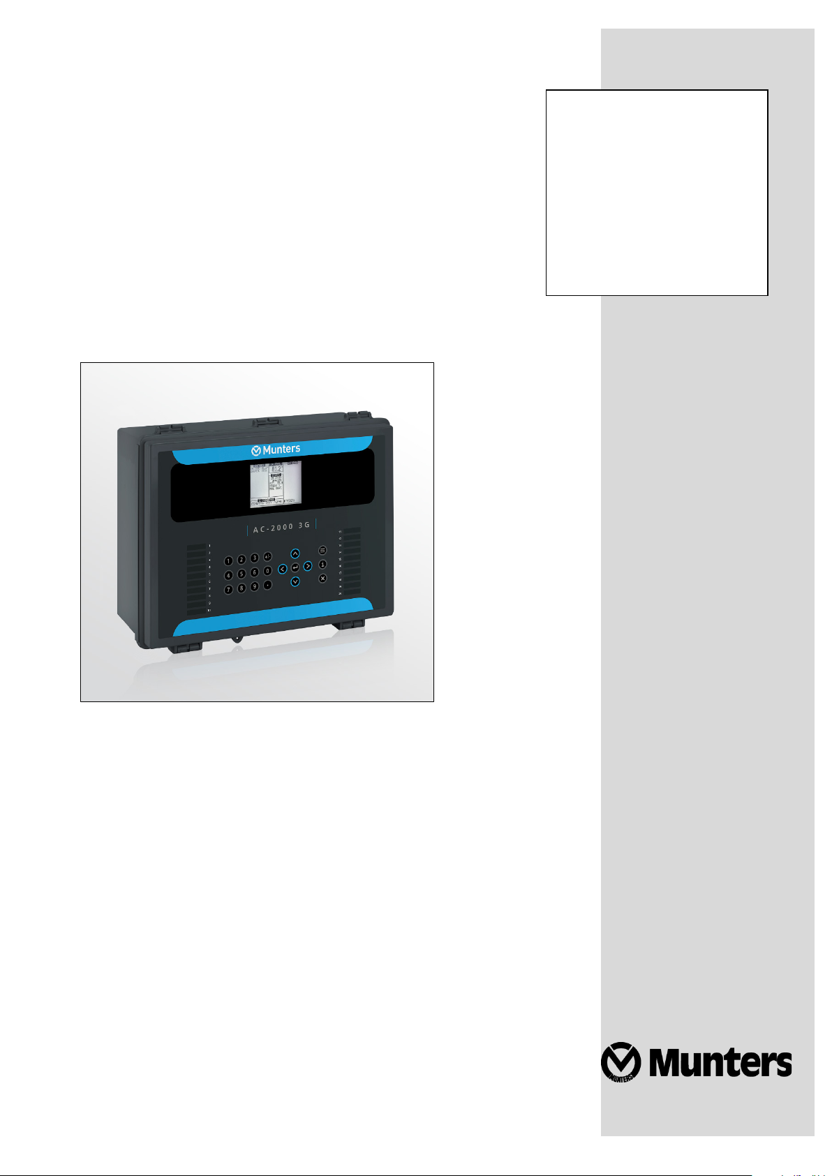
AC-2000 3G
Climate Controller
Ag/MIS/Um/Gb-2792-01/21 Rev 1.0
P/N: 117336
Page 2

AC-2000 3G
Manual for use and maintenance
Revision: N.1.0 of 01/2021
Product Software: 9.19
This manual for use and maintenance is an integral part of the apparatus together with the attached
technical documentation.
This document is destined for the user of the apparatus: it may not be reproduced in whole or in part,
committed to computer memory as a file or delivered to third parties without the prior authorization of
the assembler of the system.
Munters reserves the right to effect modifications to the apparatus in accordance with technical and
legal developments.
© Munters AB, 2018 2
Page 3

Index
Chapter page
1
INTRODUCTION -------------------------------------------------------------------------------------------------------------------------------------- 3
1.1 Disclaimer
1.2 Introduction
1.3 Notes
2
INTRODUCTION TO THE AC-2000 3G ------------------------------------------------------------------------------------------- 4
2.1 Keypad
2.2 Hot Screens
2.3 Standard Display
2.4 Main Menu Icons
2.5 Cold Start
3
CONTROL MENU ------------------------------------------------------------------------------------------------------------------------------------ 9
3.1 Temperature Curve
3.1.1 Temperature Curve Help | Set Definitions
3.1.2 Radiant Heaters Help | Set Definitions
3.1.3 Cycle Heaters | Set Definitions
3.1.4 Variable Heater Help | Set Definitions
3.1.5 Variable Floor Heater | Set Definitions
3.2 Introduction to Humidity, Ammonia, and CO2 Treatment
3.3 Humidity Treatment
3.3.1 Humidity Treatment Help | Set Definitions
3.4 CO2 Treatment
3.4.1
3.5 Min/Max Level
3.5.1 By Day and By Soft Days Curve
3.5.2 By Time
3.5.3 Day Soft Min.
3.5.4 By Weight
3.6 Static Pressure
3.6.1 Disabling the Static Pressure Sensor
3.6.2 Static Pressure Help | Set Definitions
3.6.3 Multi Stage Tunnel Curtains
3.7 Control Mode
3.8 System Parameters
-----------------------------------------------------------------------------------------------------------------------------------------------------------------------
--------------------------------------------------------------------------------------------------------------------------------------------------------------------
--------------------------------------------------------------------------------------------------------------------------------------------------------------------------------
----------------------------------------------------------------------------------------------------------------------------------------------------------------------------
-------------------------------------------------------------------------------------------------------------------------------------------------------------------
-------------------------------------------------------------------------------------------------------------------------------------------------------
------------------------------------------------------------------------------------------------------------------------------------------------------
-----------------------------------------------------------------------------------------------------------------------------------------------------------------------
---------------------------------------------------------------------------------------------------------------------------------------------------
.....................................................................
...........................................................................
..........................................................................................
...........................................................................
...........................................................................
--------------------------------------------------------------
------------------------------------------------------------------------------------------------------------------------------------------------
.....................................................................
--------------------------------------------------------------------------------------------------------------------------------------------------------
CO2 Treatment Help | Set Definitions
--------------------------------------------------------------------------------------------------------------------------------------------------------
........................................................................................................................................
............................................................................................................................
...................................................................................................................................
-----------------------------------------------------------------------------------------------------------------------------------------------------------
.................................................................................................
-----------------------------------------------------------------------------------------------------------------------------------------------------------
-------------------------------------------------------------------------------------------------------------------------------------------------
............................................................................
........................................................................................
.................................................................................
...............................................................................
10
11
12
13
16
17
17
18
19
20
20
21
21
22
22
27
27
28
28
29
29
3
3
3
4
5
6
7
8
9
© Munters AB, 2018 3
Page 4

3.9 Ammonia Treatment
----------------------------------------------------------------------------------------------------------------------------------------------
3.9.1 Ammonia Treatment Help | Set Definitions
....................................................................
30
31
4
DEVICE MENU --------------------------------------------------------------------------------------------------------------------------------------- 32
4.1 Levels of Ventilation
4.1.1 Levels of Ventilation Help | Set Definitions
4.1.2 Wind Chill
4.2 Variable Speed Fan Levels
4.3 Vent & Curtain Levels
4.3.1 Vent & Curtain Levels Help | Set Definitions
4.4 Stir Fan Levels
4.5 Stir Fan Program
4.5.1 Stir Fan Program Help | Set Definitions
4.6 Cool Pad
----------------------------------------------------------------------------------------------------------------------------------------------------------------------
4.6.1 Cool Pad Help | Set Definitions
4.7 Foggers
-------------------------------------------------------------------------------------------------------------------------------------------------------------------------
4.7.1 Foggers Help | Set Definitions
4.8 Light
---------------------------------------------------------------------------------------------------------------------------------------------------------------------------------
4.8.1 Light Help | Set Definitions
4.9 Water & Feed
4.9.1 Water and Feed Help | Set Definitions
4.10 Extra Systems
4.11 Water on Demand
4.11.1 Relay Control
4.11.2 Sensor Control
-----------------------------------------------------------------------------------------------------------------------------------------------
....................................................................
...................................................................................................................................
--------------------------------------------------------------------------------------------------------------------------------
--------------------------------------------------------------------------------------------------------------------------------------------
.................................................................
------------------------------------------------------------------------------------------------------------------------------------------------------------
------------------------------------------------------------------------------------------------------------------------------------------------------
..........................................................................
.........................................................................................
...........................................................................................
..................................................................................................
-----------------------------------------------------------------------------------------------------------------------------------------------------------
..........................................................................
------------------------------------------------------------------------------------------------------------------------------------------------------------
-------------------------------------------------------------------------------------------------------------------------------------------------
.............................................................................................................................
..........................................................................................................................
33
34
35
35
36
37
37
38
39
40
41
42
42
43
44
45
46
47
47
48
48
5
MANAGE MENU ---------------------------------------------------------------------------------------------------------------------------------- 50
5.1 Inventory
5.2 Feed Inventory
5.2.1 Feed Inventory Help | Set Definitions
5.3 Time & Date
5.4 Growth Day & Flock
5.5 Alarm Setting
5.5.1 Alarm Setting Help | Set Definitions
5.6 Alarm Reset
5.7 Password
6
SCALE MENU ----------------------------------------------------------------------------------------------------------------------------------------- 57
6.1 Scale Layout
6.2 General Settings
6.2.1 General Settings Help | Set Definitions
6.3 Bird Scale Setting
----------------------------------------------------------------------------------------------------------------------------------------------------------------------
----------------------------------------------------------------------------------------------------------------------------------------------------------
..............................................................................
---------------------------------------------------------------------------------------------------------------------------------------------------------------
---------------------------------------------------------------------------------------------------------------------------------------------
-------------------------------------------------------------------------------------------------------------------------------------------------------------
.................................................................................
----------------------------------------------------------------------------------------------------------------------------------------------------------------
----------------------------------------------------------------------------------------------------------------------------------------------------------------------
--------------------------------------------------------------------------------------------------------------------------------------------------------------
------------------------------------------------------------------------------------------------------------------------------------------------------
..........................................................................
----------------------------------------------------------------------------------------------------------------------------------------------------
50
51
51
51
52
52
54
56
56
57
57
58
58
© Munters AB, 2018 4
Page 5

6.3.1 Bird Scale Setting, Version 9.18 and Below
6.3.2 Bird Scale Setting, Version 9.19
6.4 Bird Curve/Bird Weight
--------------------------------------------------------------------------------------------------------------------------------------
6.4.1 Bird Curve, Version 9.18 and Below
6.4.2 Bird Weight, Version 9.19
6.5 History
---------------------------------------------------------------------------------------------------------------------------------------------------------------------------
...................................................................................................
6.5.1 History, Version 9.18 and Below
6.5.2 History, Version 9.19
6.6 Feed Conversion
6.7 Test
6.8 Calibration
----------------------------------------------------------------------------------------------------------------------------------------------------------------------------------
------------------------------------------------------------------------------------------------------------------------------------------------------------------
-----------------------------------------------------------------------------------------------------------------------------------------------------
.............................................................................................................
.................................................................
........................................................................................
...............................................................................
.......................................................................................
58
59
59
60
60
61
61
62
63
63
63
7
HISTORY MENU ------------------------------------------------------------------------------------------------------------------------------------ 65
7.1 Temperature
7.2 Humidity
7.3 CO2
-------------------------------------------------------------------------------------------------------------------------------------------------------------------------------
7.4 Water
7.5 Feed
--------------------------------------------------------------------------------------------------------------------------------------------------------------------------------
7.6 Mortality
7.7 Heaters
7.8 Radiant Heaters
7.9 Alarms
7.10 Table of Events
7.11 History View
8
TEST MENU --------------------------------------------------------------------------------------------------------------------------------------------- 68
8.1 Relays
8.2 Alarm
8.3 Analog Sensors
8.4 Digital Sensors
8.5 Analog Output
8.6 Static Pressure
8.7 Communication
---------------------------------------------------------------------------------------------------------------------------------------------------------------
-----------------------------------------------------------------------------------------------------------------------------------------------------------------------
-----------------------------------------------------------------------------------------------------------------------------------------------------------------------------
-----------------------------------------------------------------------------------------------------------------------------------------------------------------------
--------------------------------------------------------------------------------------------------------------------------------------------------------------------------
-------------------------------------------------------------------------------------------------------------------------------------------------------
---------------------------------------------------------------------------------------------------------------------------------------------------------------------------
---------------------------------------------------------------------------------------------------------------------------------------------------------
---------------------------------------------------------------------------------------------------------------------------------------------------------------
----------------------------------------------------------------------------------------------------------------------------------------------------------------------------
------------------------------------------------------------------------------------------------------------------------------------------------------------------------------
--------------------------------------------------------------------------------------------------------------------------------------------------------
----------------------------------------------------------------------------------------------------------------------------------------------------------
---------------------------------------------------------------------------------------------------------------------------------------------------------
-----------------------------------------------------------------------------------------------------------------------------------------------------------
--------------------------------------------------------------------------------------------------------------------------------------------------------
65
65
65
66
66
66
66
67
67
67
67
68
68
69
69
69
70
70
9
SERVICE MENU ------------------------------------------------------------------------------------------------------------------------------------- 71
9.1 Temperature Calibration
9.2 Humidity Calibration
9.3 CO2 Sensor Calibration
9.4 Static Pressure Calibration
9.5 Light Sensor Calibration
9.6 Feed Calibration
------------------------------------------------------------------------------------------------------------------------------------------------------
9.7 Water Calibration
© Munters AB, 2018 5
-------------------------------------------------------------------------------------------------------------------------------------
---------------------------------------------------------------------------------------------------------------------------------------------
------------------------------------------------------------------------------------------------------------------------------------
---------------------------------------------------------------------------------------------------------------------------------
--------------------------------------------------------------------------------------------------------------------------------------
--------------------------------------------------------------------------------------------------------------------------------------------------
71
72
72
73
74
74
75
Page 6

9.8 Ventilation Potentiometer Calibration
9.9 Save Settings to SD Card
9.10 Read from SD Card
9.10.1 Load Settings Report
9.11 WOD Calibration
---------------------------------------------------------------------------------------------------------------------------------------------------
----------------------------------------------------------------------------------------------------------------------------------
-----------------------------------------------------------------------------------------------------------------------------------------------
...............................................................................................................
9.11.1 WOD Calibration Help | Set Definitions
---------------------------------------------------------------------------------------------------------
........................................................................
75
76
77
77
78
78
10 INSTALL MENU -------------------------------------------------------------------------------------------------------------------------------------- 79
10.1 Setup
10.1.1 Static Pressure Unit Definition
10.2 Relay Layout
10.2.1 Supported Relays
10.2.2 Relay Layout – Help | Set Definitions
10.3 Analog Sensors
10.4 Digital Sensors
10.5 Analog Output
10.6 Vent/Curtain Setup
10.6.1 Using Time to Calibrate
10.6.2 Using a Potentiometer to Calibrate
10.6.3 Vent/Curtain Help | Set Definitions
10.7 Temperature Definition
10.8 Fan Air Capacity
10.9 House Dimensions
10.10 Communication
------------------------------------------------------------------------------------------------------------------------------------------------------------------------------
..............................................................................................
--------------------------------------------------------------------------------------------------------------------------------------------------------------
.....................................................................................................................
..............................................................................
--------------------------------------------------------------------------------------------------------------------------------------------------------
----------------------------------------------------------------------------------------------------------------------------------------------------------
---------------------------------------------------------------------------------------------------------------------------------------------------------
------------------------------------------------------------------------------------------------------------------------------------------------
.........................................................................................................
...................................................................................
..................................................................................
----------------------------------------------------------------------------------------------------------------------------------------
-----------------------------------------------------------------------------------------------------------------------------------------------------
--------------------------------------------------------------------------------------------------------------------------------------------------
--------------------------------------------------------------------------------------------------------------------------------------------------------
79
80
80
80
81
81
82
83
83
83
84
84
85
86
86
87
11 TECHNICAL SPECIFICATIONS --------------------------------------------------------------------------------------------------------- 88
12 INSTALLATION --------------------------------------------------------------------------------------------------------------------------------------- 89
12.1 Precautions
12.1.1 Grounding
12.1.2 Filtering
12.1.3 Checking the Battery Level
12.1.4 Frequency Inverters
12.2 Mounting the Unit
12.3 AC-2000 3G Wiring
12.3.1 Board Layout
12.3.2 Relays
12.3.3 High Voltage Wiring (Relays)
12.3.4 Terminal Setup
12.4 Communication Card
12.4.1 Wiring
12.4.2 Communication Card Grounding
-----------------------------------------------------------------------------------------------------------------------------------------------------------------
..................................................................................................................................
........................................................................................................................................
...................................................................................................
.................................................................................................................
---------------------------------------------------------------------------------------------------------------------------------------------------
--------------------------------------------------------------------------------------------------------------------------------------------
.............................................................................................................................
...........................................................................................................................................
.............................................................................................
..........................................................................................................................
-------------------------------------------------------------------------------------------------------------------------------------------
..........................................................................................................................................
...................................................................................
101
89
89
89
89
89
90
91
91
92
93
94
98
99
© Munters AB, 2018 6
Page 7

12.4.3 Termination and 5V Setup
.................................................................................................
101
13 APPENDIX A: DATA OUTPUT ---------------------------------------------------------------------------------------------------------- 104
14 APPENDIX B: INSTALLING A CO2 SENSOR AND SECOND HUMIDITY SENSOR ---- 107
14.1 Humidity Sensor
14.2 CO2 Sensor
----------------------------------------------------------------------------------------------------------------------------------------------------
------------------------------------------------------------------------------------------------------------------------------------------------------------
108
108
15 APPENDIX C: AC-2000 3G PANEL MOUNT ---------------------------------------------------------------------------- 110
15.1 Metal Assembly Precautions
15.2 Panels
15.3 Panel Dimensions
--------------------------------------------------------------------------------------------------------------------------------------------------------------------------
-------------------------------------------------------------------------------------------------------------------------------------------------
15.4 Connecting the Metal Panels
15.4.1 Precautions
..............................................................................................................................
15.4.2 Panel Mount Cable Connections
-------------------------------------------------------------------------------------------------------------------------
------------------------------------------------------------------------------------------------------------------------
....................................................................................
110
110
111
111
111
112
16 APPENDIX D: ELECTRICAL GROUNDING FOR CONTROLLERS ---------------------------------------- 113
16.1 Ground Rods
16.2 Ground Wire
16.3 Ground Clamps
16.4 What Should Be Grounded?
----------------------------------------------------------------------------------------------------------------------------------------------------------
----------------------------------------------------------------------------------------------------------------------------------------------------------
----------------------------------------------------------------------------------------------------------------------------------------------------
------------------------------------------------------------------------------------------------------------------------
113
114
114
114
17 WARRANTY ------------------------------------------------------------------------------------------------------------------------------------------ 115
© Munters AB, 2018 7
Page 8

1 Introduction
1.1 Disclaimer
Munters reserves the right to make alterations to specifications, quantities, dimensions etc. for production
or other reasons, subsequent to publication. The information contained herein has been prepared by
qualified experts within Munters. While we believe the information is accurate and complete, we make no
warranty or representation for any particular purposes. The information is offered in good faith and with
the understanding that any use of the units or accessories in breach of the directions and warnings in this
document is at the sole discretion and risk of the user.
1.2 Introduction
Congratulations on your excellent choice of purchasing an AC-2000 3G!
In order to realize the full benefit from this product it is important that it is installed, commissioned and
operated correctly. Before installation or using the controller, this manual should be studied carefully. It is
also recommended that it is kept safely for future reference. The manual is intended as a reference for
installation, commissioning and day-to-day operation of the Munters Controllers.
1.3 Notes
Date of release: July 2010
Munters cannot guarantee to inform users about the changes or to distribute new manuals to them.
All rights reserved. No part of this manual may be reproduced in any manner whatsoever without the
expressed written permission of Munters. The contents of this manual are subject to change without notice.
© Munters AB, 2021 3
Page 9
2 Introduction to the AC-2000 3G
This document describes the AC-2000 3G Precision Mode operation.
Computerized Electronic Controllers such as the AC-2000 3G advance the producer’s ability to grow
high quality eggs by accurately controlling the environment. Instead of struggling with individual
thermostats for heat zones and ventilation, AC-2000 3G brings them all together into one convenient
place with great accuracy. The AC-2000 3G optimizes and precisely applies your equipment and energy
sources to most benefit from the accuracy of your computer and sensors.
The AC-2000 3G coordinates your ventilation equipment in precise levels of ventilation to provide the
optimal fresh air balanced with heating costs. The light and feed clocks provide additional channels for
greater capability. Besides advanced Cooling Pad methods, you benefit from superior stir fan programs
to recover ceiling heat and other features. Precision Mode’s additional features enable you to improve
your profitability significantly.
AC-2000 3G provides a variety of management and history utilities. You can choose from simple
overviews, or fully detailed
by the minute
records of minimum, maximum and average temperatures for
each individual sensor. The unique Table of Events records the moment of every significant action taken
by the AC-2000 3G and, optionally, its operator.
•
Keypad, page 4
•
Hot Screens, page 5
•
Standard Display, page 6
•
Main Menu Icons, page 7
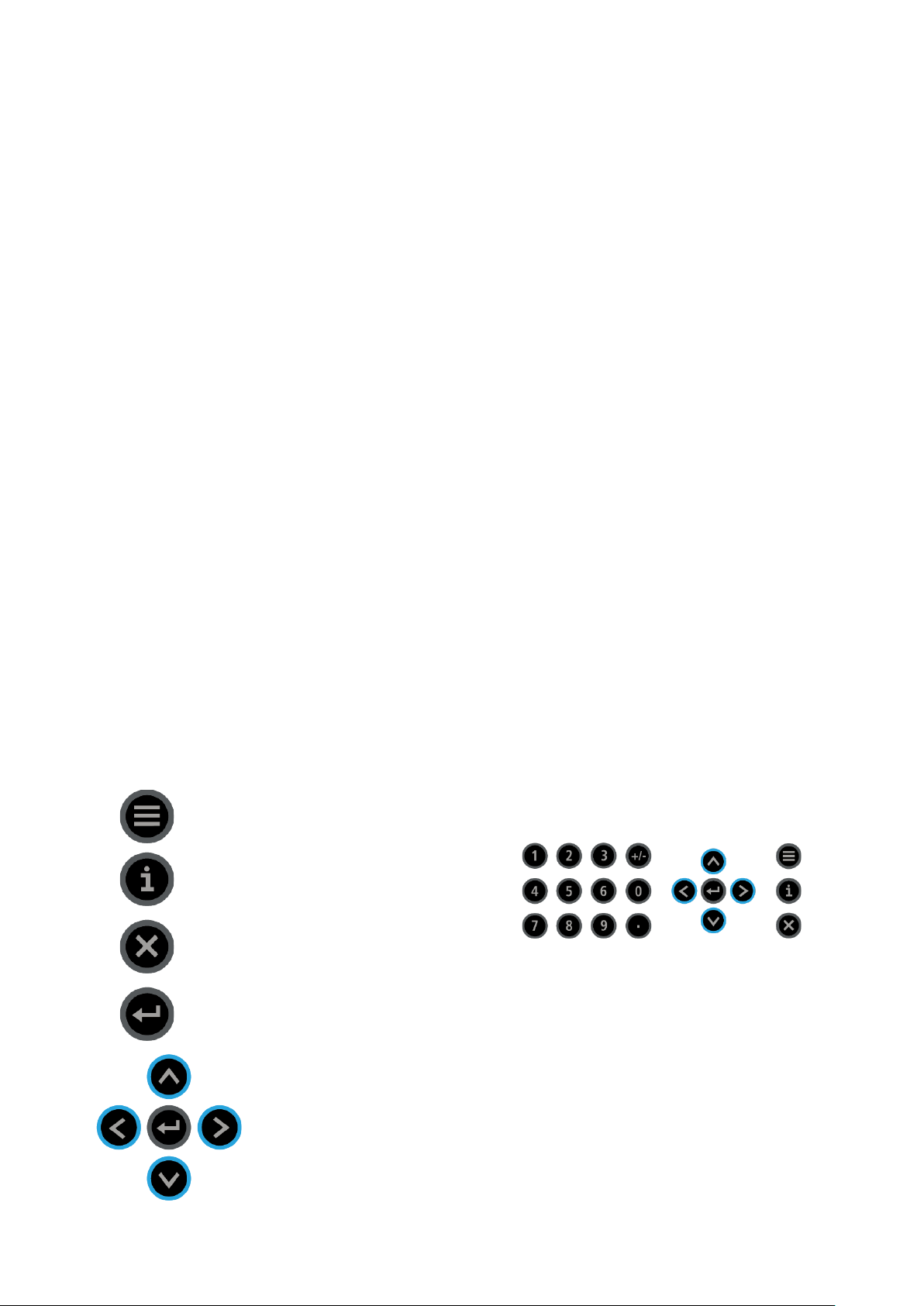
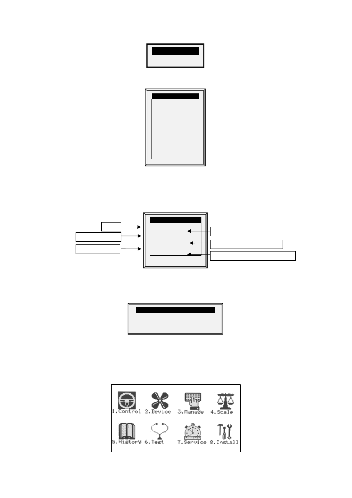
2.1 Keypad
Enter main menu, also acts as "ESC" or "Back" key
Access help screens and graphs
Erase typing mistakes
Enter menus, values, open windows
Scroll up, down, left and right
© Munters AB, 2021 4
Page 10
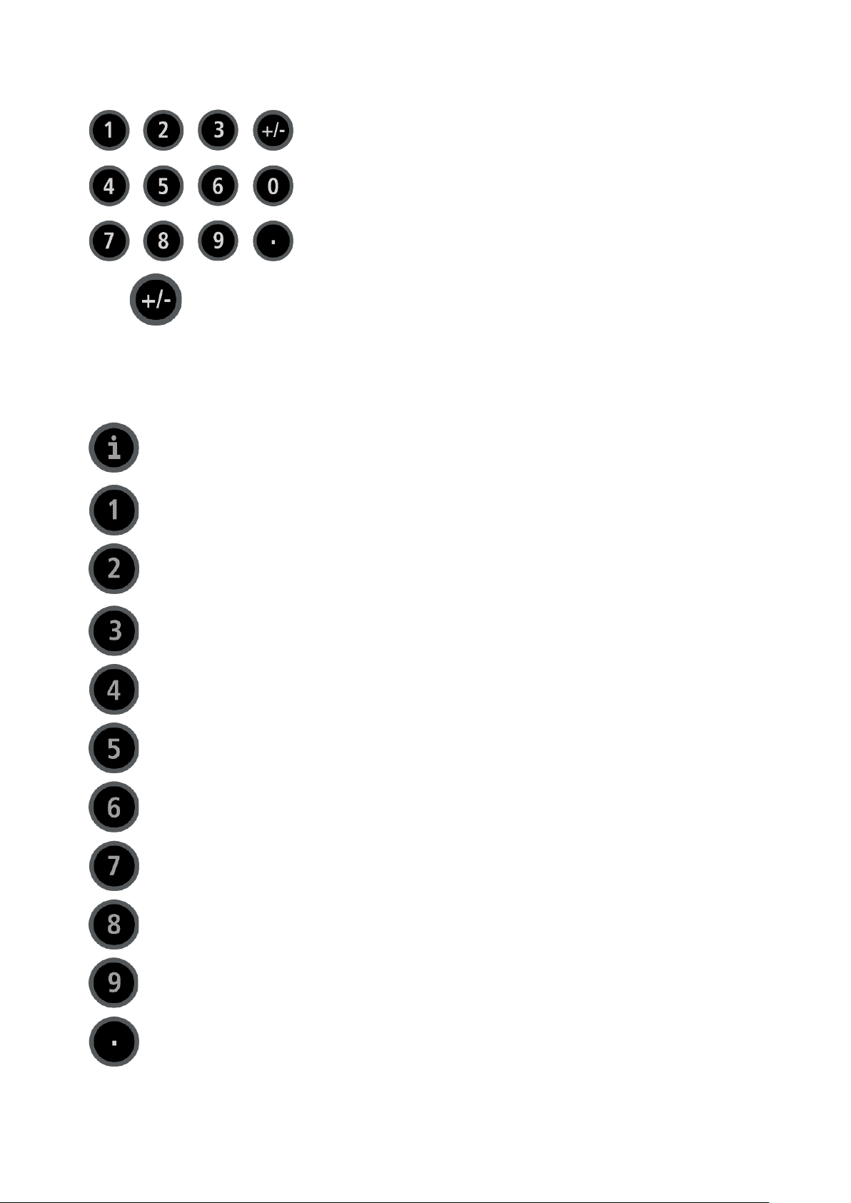
Enter values, select options and make selections
Toggle between positive and negative values and mark check boxes.
2.2 Hot Screens
Many of the keys serve as shortcuts. Here are the main ones:
Software version
Return to standard main screen
Temperature, Humidity Status, and Wind Chill Temperature
NOTE If two humidity sensors are installed, Hot Screen 2 displays their average.
Curve status
Curtain tunnel, vent, and attic opening positions
Bird scale status
Light status
Analog output status
Temperature sensors
Feed bin status
Scan through Hot Screens for five seconds each
© Munters AB, 2021 5
Page 11
Stir fans status
Increase/ decrease offset from temperature setting from the standard display only
SENSORS
AV. TEMP.
ACTI VE
Temp1
37.9°
27.5°
Heat 1 Temp2
16.2°
Heat. Hi
1
Temp3
28.2°
STATUS
Tun. Fan
E. Tmp1
28.8°
08:53:06
Exh. Fan
E. Tmp2
28.4°
Day: 5
Stir
Press.
23
Set:
25.0
Cool P.
Out T.
23.9°
Level:
3
Fogger
Hum. In
58.7%
Min.
Vent
Curt. 1
100%
Hum. Out
61.9%
FanOff:
176
Curt. 2
100%
Weight
0.000
Curt. 3
0%
Weights
0 Curt. 4
0%
4 MESSAGES
Ext. Sys
(2) Low Feed At Bin 2
Alarm SENSORS
Temp1
37.9°
Temp2
16.2°
Temp3
28.2°
E. Tmp1
28.8°
E. Tmp2
28.4°
Press.
23
Out T.
23.9°
Hum. In
58.7%
Hum. Out
61.9%
Weight
0.000
Weights
0
Air Status (refer to Weight Hot Screen, page 26 for details on this screen)
(hold both keys) – defined in the T
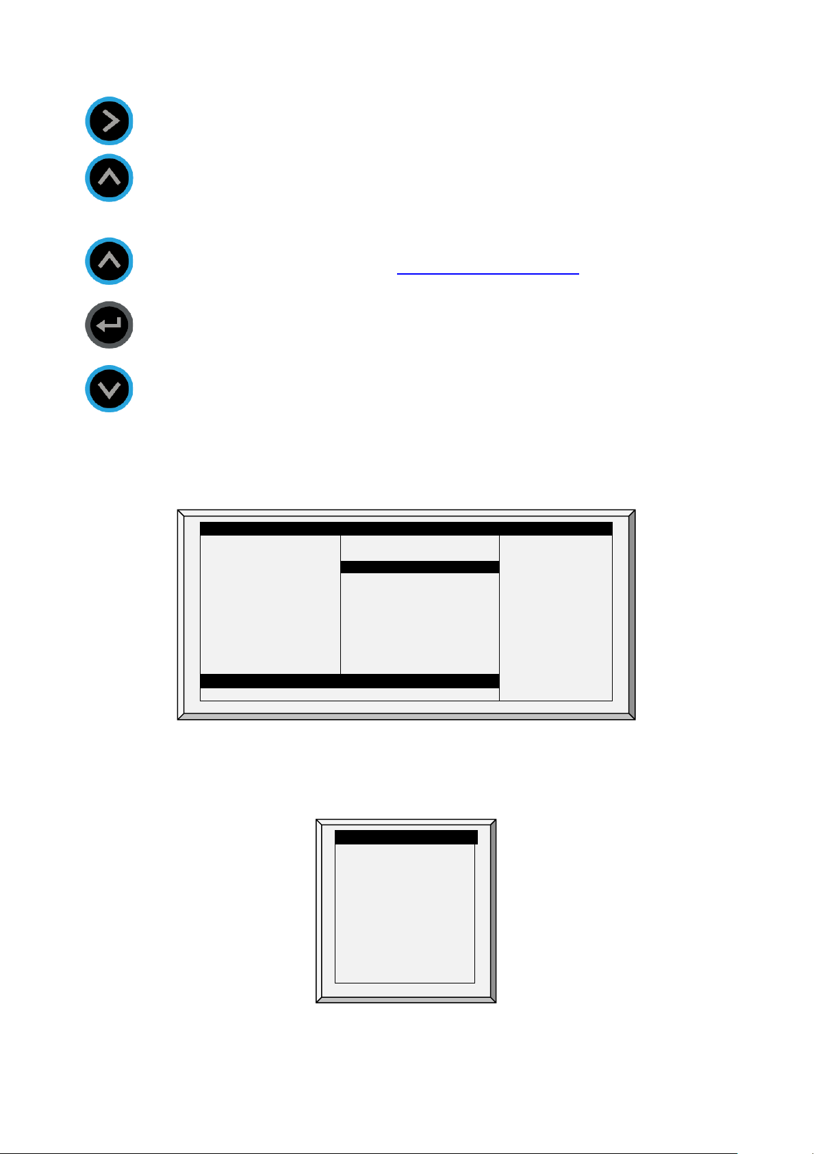
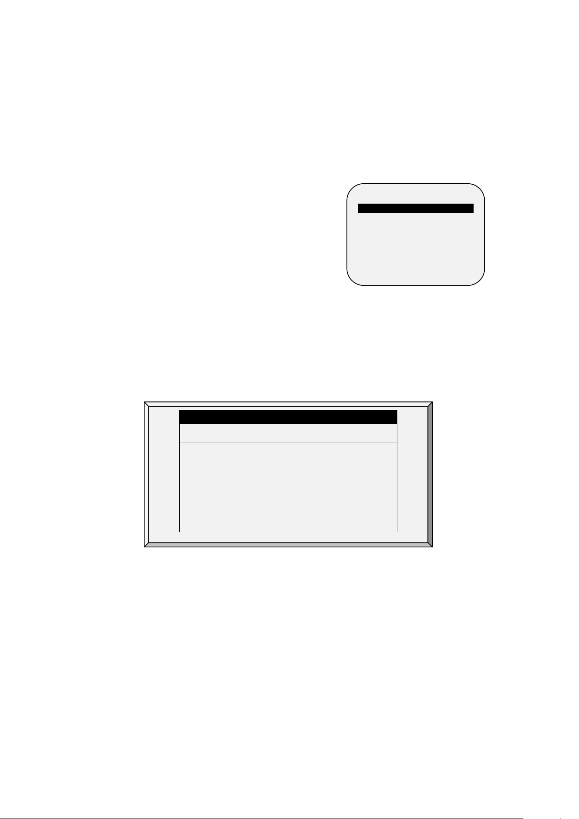
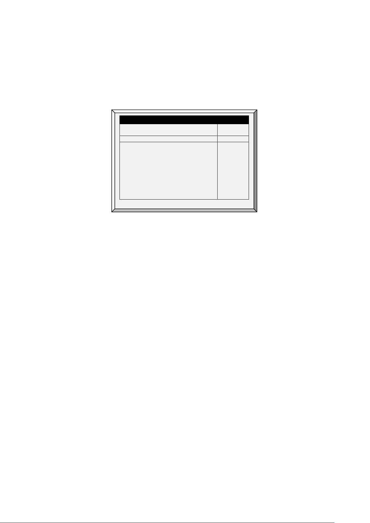
2.3 Standard Display
The main screen consists of the following parts.
EMPERATURE CURVE HELP | SET
1. Sensors: Displays individual sensor readings. Temperature sensors marked with dark squares
form the current average temperature.
o
Filled square: Indicates the sensor participates in the average calculation.
o
Empty square: Indicates the sensor does not participate in the average calculation.
Go to Table 1: Sensor Readings page 104, to view all the possible sensors.
2. Av. Temp: Reports the current average temperature. This example is in Celsius, but yours may be
in Fahrenheit.
© Munters AB, 2021 6
Page 12
27.5°
ACTI VE
Heat 1 Heat. Hi
1
Tun. Fan
Exh. Fan
Stir
Cool P.
Fogger
Curt. 1
100%
Curt. 2
100%
Curt. 3
0%
Curt. 4
0%
STATUS
08:53:06
Day: 5
Set:
25.0
Level:
3
Min.
Vent
FanOff:
176 4 MESSAGES
(2) Low Feed At Bin 2
Te
Time
Controller State
Growth day
Current level of ventilation
Time until
Av. Temp
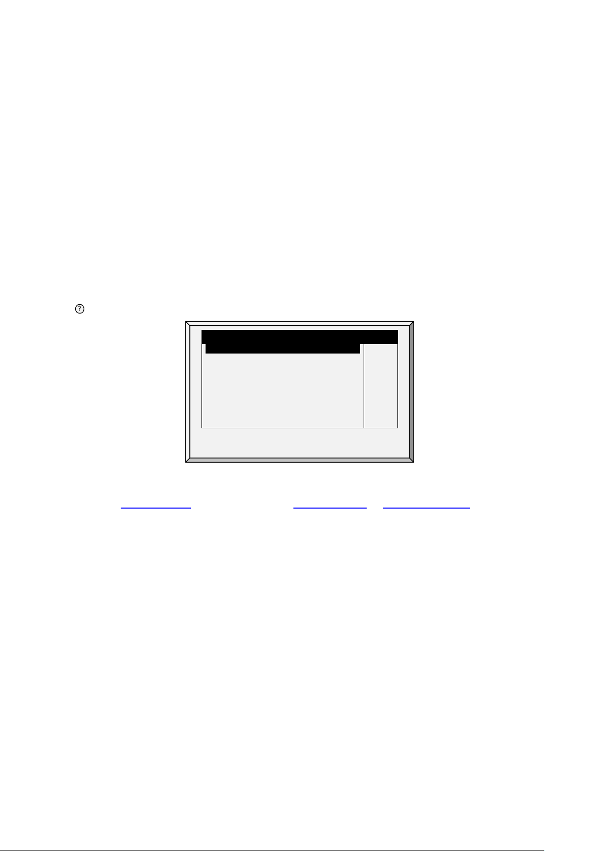
3. Active: Displays the output relay list. The filled black boxes indicate active outputs. Controller
also informs the position of inlets and curtains, as well as the number of operating heaters or fans.
Go to Table 2: Output List (Active), page 104 to view all the available readings (ACTIVE).
The ACTIVE screen shows rectangular markers by the outputs. Filled rectangles indicate operating
outputs; empty rectangles indicate outputs that are off.
4. Status: Provides important general information such as the time and ventilation mode.
mp set to
cycle ends operation
Go to Table 1: Sensor Readings, page 104 to view all the available readings.
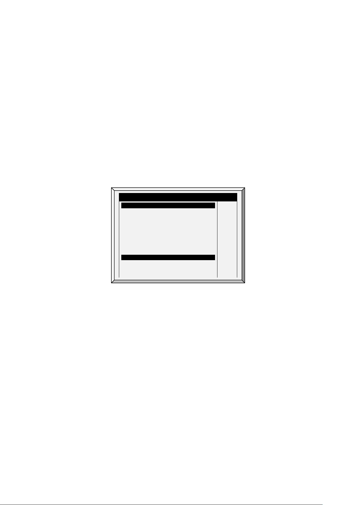
5. Messages: Displays important messages/alarms. The title bar displays the number of important
messages, and if there are several messages, they each appear in turn.
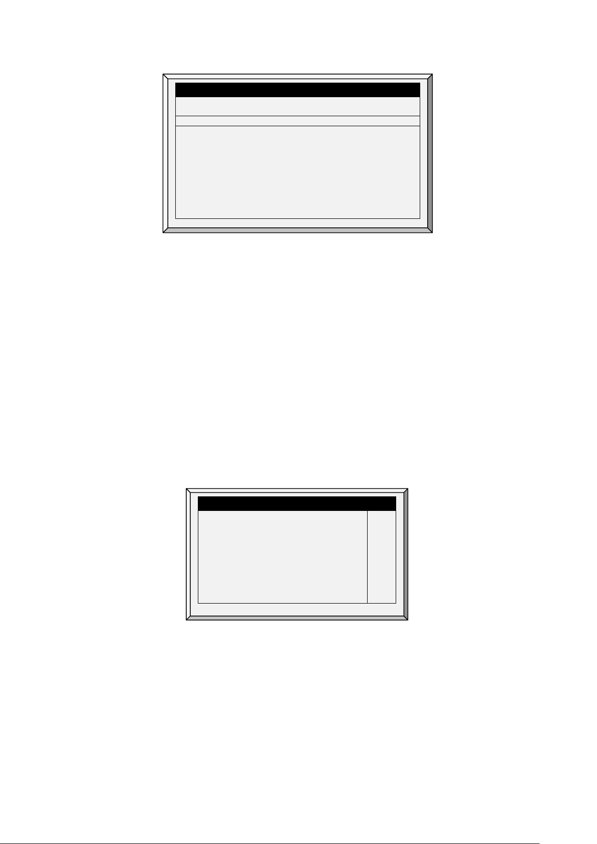
2.4 Main Menu Icons
1. To enter the Main Menu screen, press Menu.
2. To select an option, press Enter.
© Munters AB, 2021 7
1. Control temperature, humidity, ventilation, static pressure and system parameters.
Page 13

2. Define equipment settings
3. Manage inventory, livestock, and alarm/password settings.
4. Set, calibrate and test bird scales.
5. View history of all controller functions.
6. Test to see switches, relays, communication, and alarms are functioning properly.
7. Calibrate temperature, humidity, ventilation, static pressure, feed, water, read/save to plug.
8. Install sensors, devices, communication, etc.
2.5 Cold Start
To perform a cold start:
1. Disconnect the power cable from the power source.
2. Reapply power while pressing Delete. The Cold Start screen appears.
3. Select Yes.
© Munters AB, 2021 8
Page 14
Temperature Curve, page 9
CONTROL
8. AMMONIA TREATMENT
Day
Target
Heat
Tunnel
Alarm
Low
High
T.Hi
1
48
89.0
68.0
89.0
66.0
100.0
73.0
84.0
60.0
102.0
83.0
103
103
3 Control menu
The following sections detail the following functions:
•
•
Introduction to Humidity,
Ammonia, and CO2 Treatment,
page 17
•
CO2 Treatment, page 19
•
Min/Max Level, page 20
•
Static Pressure, page 27
•
Control Mode, page 28
•
System Parameters, page 29
•
Ammonia Treatment, page 30
1. TEMPERATURE CURVE
2. HUMIDITY TREATMENT
3. CO2 TREATMENT
4. MIN/MAX LEVEL
5. STATIC PRESSURE
6. CONTROL MODE
7. SYSTEM PARAMETERS
3.1 Temperature Curve
This screen sets the temperature targets according to the bird age.
TEMPERATURE CURVE
2
1. In
Install > Analog Sensors
of sensors as temperature sensors. When using more than one sensor, AC-2000 3G begins
treatments based on the average.
2. In
Install > Relays Layout
3. If required, go to
4. In
Install > Temperature Definition
devices. If a zone does not have an assigned sensors, calculations are based on the current
average temperature.
5. In
Control > Temperature Curve
o
Set up to 20 lines, 999 growth days. When a curve is not required, enter temperatures in
the first line only.
89.0
3
87.0
7
84.0
15
82.0
21
79.0
28
76.0
35
72.0
42
70.0
(refer to Analog Sensors, page 81), designate the required number
, define the required number of relays as Heaters.
Service > Temperature Calibration
89.0
87.0
83.0
81.0
78.0
74.0
70.0
68.0
99.0
97.0
91.0
89.0
86.0
81.0
77.0
75.0
84.0
82.0
80.0
78.0
75.0
71.0
67.0
63.0
, calibrate the sensors.
, assign specific sensors brood setups, heater zones, and
, define the required target temperature curve
102.0
95.0
95.0
93.0
90.0
87.0
84.0
83.0
103
103
103
103
103
103
103
103
© Munters AB, 2021 9
Define: Day: Sets growth day. You can program negative growth days up to -7 for
pre-warming. To enter a negative growth day, type the day number followed by
the +/- key.
Page 15
TEMPERATURE CURVE
Non Brood Area Diff. From Heat
-3.0
6. In
Manage > Alarm Setting
7. If required set the:
o
o
o
o
o
Target: Set the desired temperature.
Heat: Set the temperature to stop heat.
Tunnel: Set the temperature for tunnel ventilation to begin.
Alarm Low & High: Set average temperature alarm limits. See Manage | Alarm
Settings for zone alarm settings.
, set the Sensor Alarms (page 52).
Temperature Curve Help | Set Definitions, page 10
Radiant Heaters Help | Set Definitions, page 11
Cycle Heaters | Set Definitions, page 12
Variable Heater Help | Set Definitions, page 13
Variable Floor Heater | Set Definitions, page 16
3.1.1 T
EMPERATURE CURVE HELP | SET DEFINITIONS
While viewing the Temperature Curve menu: Press HELP, select
SYSTEM PARAMETERS
Temperature Curve Offset
Set Temp. Change Reminder (Diff)
Target Temp. Band
Heater Temp. Band
Cool Down Factor (%)
Cool Down Fast Response (Deg.)
Min Vent Below Heat Temp By:
•
Temperature Curve Offset: Adjusts all temperature curves by this amount. You can use this to
temporarily adjust all temperatures up or down for special circumstances. The curve appears in
the Status Window, and you can use the ENTER and Up or ENTER and Down hot key
combinations to change the offset.
•
Set Temperature Change Reminder (Diff): Sets the change in set temperature that triggers a
reminder for you to set backup thermostats. Often producers forget to set backup thermostats as
their birds grow from baby chicks to market age, so the AC-2000 3G reminds you. When you
press Enter to acknowledge the reminder, the AC-2000 3G logs it in the Table of Events.
•
Target Temperature Band: The size of the target temperature zone. This "Happy Zone” is
between Target Temperature and (Target Temperature + Band).
•
Heater Temperature Band: Heaters turn on at ‘Band’ degrees below Heat, and turn off at the
Heat Temperature.
SET
, and press
0.0
3.0
1.5
1.0
15
3.0
ZONE
ENTER.
NOTE Heaters operate at minimum level only; however, Radiant Heaters can operate at any
temperature or level below Tunnel.
•
Cool Down Factor (%): Minimum percentage correction towards target during each increase
ventilation level delay. If average temperature does not improve by this amount, the AC-2000
3G increases ventilation by one level.
Cool Down Fast Response (Deg.): Set a limit to the maximum degrees per minute of cooling.
•
If Average Temperature drops more than this in one minute, the AC-2000 3G decreases
© Munters AB, 2021 10
ventilation one level to avoid overshooting.
Page 16
TEMPERATURE CURVE
Radiant Ignition Time (sec)
NOTE Avoid making this parameter too small or the normal temperature variation caused by timer fans
reduces the ventilation level.
•
Min Vent Below Heat Temp By: Tells controller to go directly to Min Level in some cases.
Select from the following choices:
o
None: Operate by the normal level decrease time delay rule.
o
Zone: Go directly to minimum level if any active temperature sensor reaches heat
temperature.
o
Avg.: Go directly to minimum level if the average temperature reaches heat temperature.
•
Non Brood Area Diff. From Heat: Set differential temperature for non-brood heaters. You
normally use this to set temperatures in unoccupied areas.
NOTE When set at -99° F the heaters are effectively disabled, since it will probably never go to 99º F
below the heater temperature. Putting this parameter at 0º sets the non-brood areas to the
heater temperature.
3.1.2 R
ADIANT HEATERS HELP | SET DEFINITIONS
To configure the radiant heaters:
1. In
Installation > Relay Layout
page 80).
2. Configure the following parameters:
o
Radiant Low – Differential from Heat Set: Set degree of difference from Heat for LOW
Radiant Heaters to begin working. This differential can be positive or negative. (default:
2.0)
o
Radiant High – Differential (Below Low Set): Set number of degrees below Radiant
Low Heaters for HIGH Radiant Heaters to begin working (default: 1.0). To ensure
proper heater ignition, Radiant High Heaters remain on for the Radiant Ignition Time
along with the Radiant Low Heaters.
o
Radiant Ignition Time (sec): Set number of seconds to power radiant ignition (default:
30).
SYSTEM PARAMETERS
0.0
3.0
1.5
1.0
15
3.0
ZONE
-3.0
0.0
1.0
30
Temperature Curve Offset
Set Temp. Change Reminder (Diff)
Target Temp. Band
Heater Temp. Band
Cool Down Factor (%)
Cool Down Fast Response (Deg.)
Min Vent Below Heat Temp By:
Non Brood Area Diff. From Heat
RADI ANT HE ATERS
Rad. Low –Diff from Heat Set
Rad. High –Diff (Below Low Set)
define at least one relay as a radiant heater (Relay Layout,
The Heater Temperature Band applies to radiant heaters as well. For example, if the Heat
Temperature is 80º F and the Heater Temperature Band is 1º F, heaters turn on at 79º F and off at
80º F. If the Radiant Low Differential is 2.0º F, radiant heaters turn off at 82º F, and on 1º F below
that (81º F). However, a Radiant High Heater turns on regardless of its temperature setting for the
Radiant Ignition Time whenever the corresponding Radiant Low Heater turns on. This feature
ensures proper flame ignition.
© Munters AB, 2021 11
Page 17
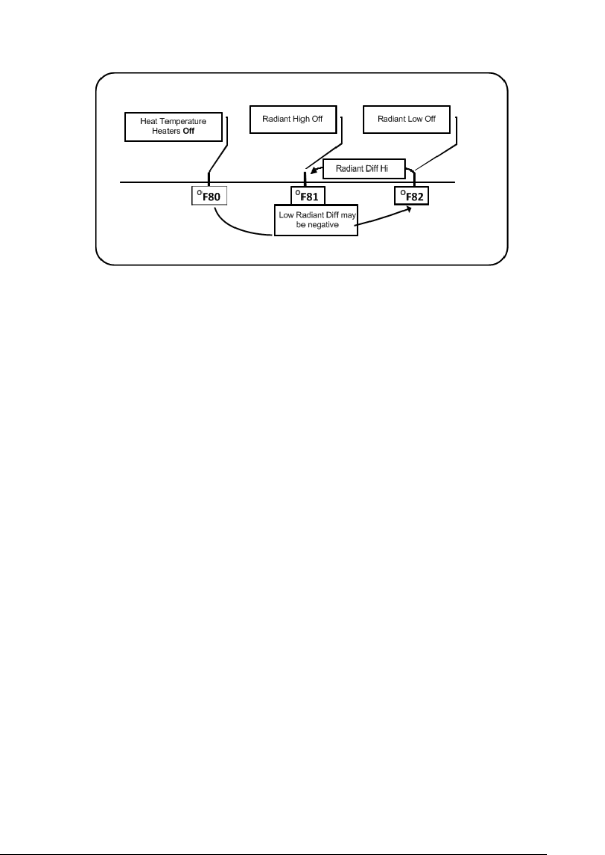
Figure 1: Radiant Heater Differentials
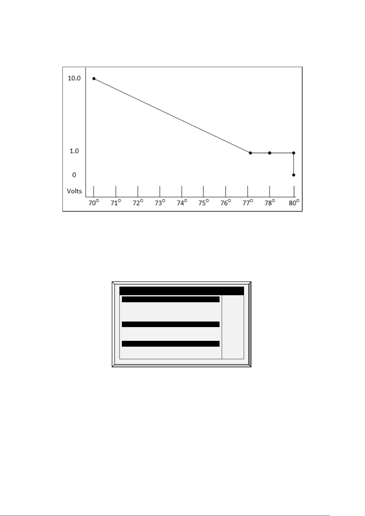
3.1.3 C
YCLE HEATERS | SET DEFINITIONS
Heat Cycle means providing heat in conjunction with the ventilation system during minimum ventilation
cycles, using heaters and fans connected to relays. When enabled, heaters operate during the fans’
cycle off time (as defined in the Levels of Ventilation Cycle Timer On and Off parameters). How does it
work?
Between the Heat Temperature and the differential temperature, heaters do not operate. When the
temperature goes below the Heat Off temperature minus the Low Heat Differential:
•
Heaters begin to operate when the exhaust or tunnel fans are off. Heaters operate for the
Minimum On Time.
•
If the temperature continues to drop, heaters operate for longer periods of time, up to the
Maximum On Time (defined in Levels of Ventilation).
•
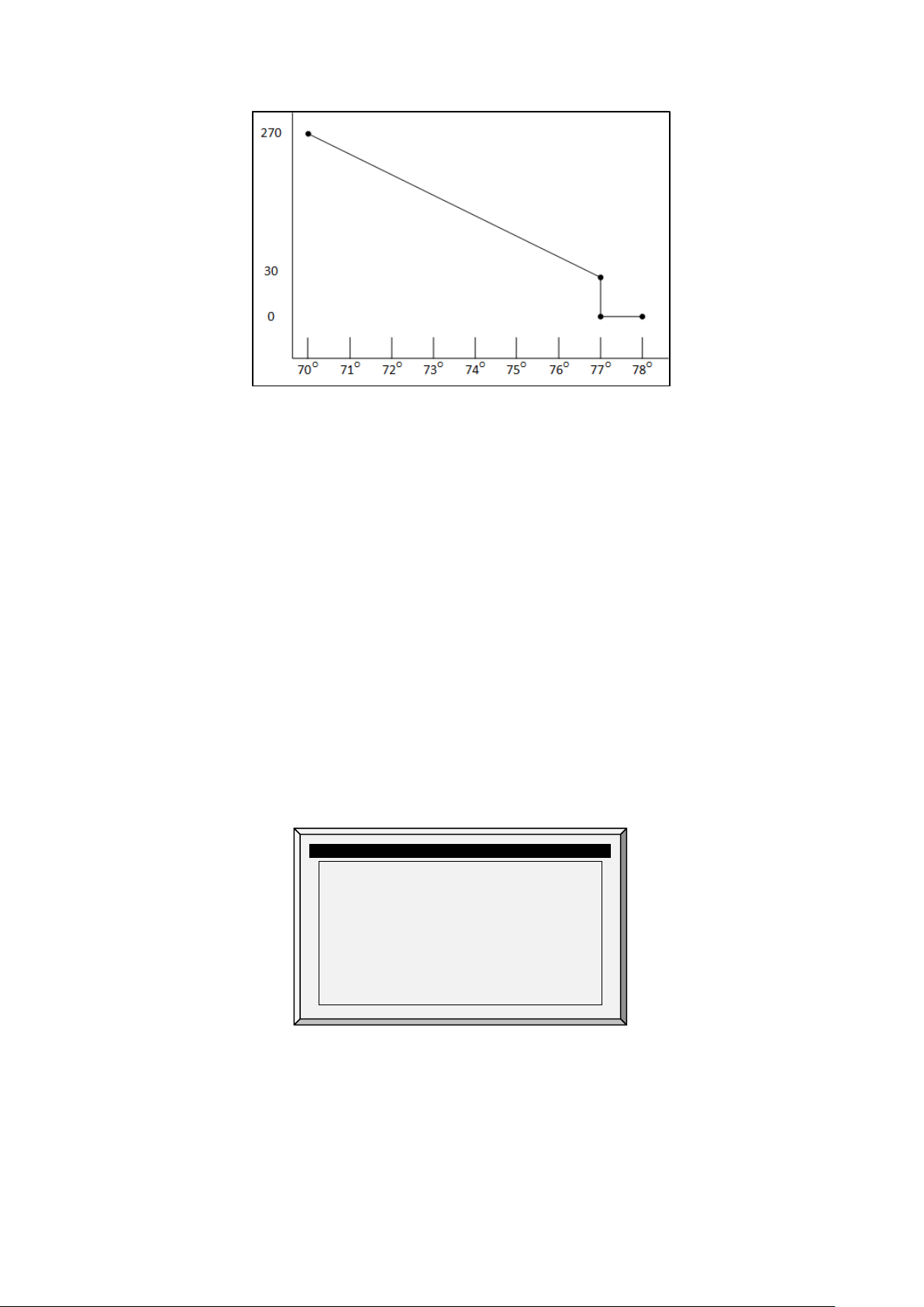
AC-2000 3G automatically generates a curve.
In this example:
•
Temperature Curve Heat Off is 78°.
•
Low Heat Differential is 1°.
•
High Heat Differential is 8°.
•
Minimum On time is 30 seconds.
•
Cycle Off time is 270 seconds.
© Munters AB, 2021 12
Page 18
Output
Function
Min
V.Out
Max
V. Out
1
Var. Heater 1
1.0
10.0 2 Var. Heater 2
1.0
10.0
1. Define the required number of heater and exhaust and/or tunnel relays (Relay Layout, page 80).
2. In Control > Control Mode, set the Heater Cycle to Yes.
3. In Control > Temperature Curve > Help, scroll to Cycle Heater.
4. Define:
o
Low Heat Differential: The differential below the Heat Off temperature, at which heating
begins and runs for the minimum amount of time.
o
High Heat Differential: The differential below the Heat Off temperature, at which heating
runs for the maximum amount of time
o
Minimum ON Time: Minimum heating time when the exhaust or tunnel fans are off.
3.1.4 V
ARIABLE HEATER HELP | SET DEFINITIONS
The AC-2000 3G Controller enables configuring up to two variable heaters. The heater output changes
according to the output of a 0 – 10 VDC device.
To configure the variable heaters:
1. In
Installation > Analog Output
configure:
a. up to two analog outputs as variable heaters
b. the minimum and maximum voltage output for each heater
ANALOG OUTPUT
Out No.
2. In
Control > Control Mode > Analog Heat Mode
•
Linear Heat
•
Proportional Heat
•
Linear Valve
, define the mode.
Refer to Control Mode, page 29 for details.
3. In Control > Temperature Curve > Help, define the parameters for each mode.
© Munters AB, 2021 13
Page 19
RADI ANT HE ATERS
8.0
3.1.4.1 Linear Heat
When Linear Mode is enabled:
•
Between the Heat Temperature and the Target temperature, heaters do not operate (meaning,
the output voltage is 0).
•
Between the Heat Temperature and the Low Difference Below Heat, heaters operate at the
minimum voltage output.
•
If the temperature continues to drop, the voltage output increases until it reaches the maximum
voltage output at the High Difference below Heat.
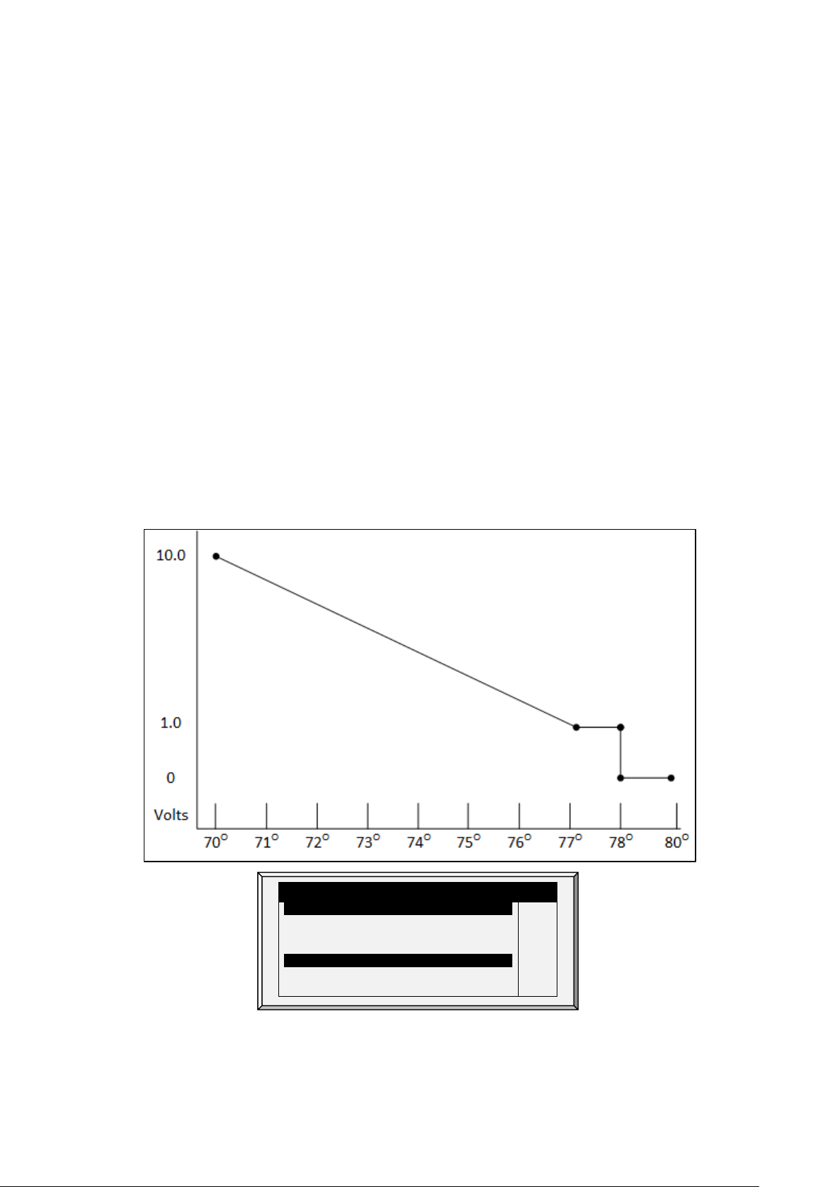
In this example:
•
Target Temperature is 80°
•
Temperature Curve Heat Off is 78°.
•
Low Heat Differential is 1°.
•
High Heat Differential is 8°.
o
If the temperature is between 77° to 78°, the output voltage is the minimum voltage
defined in Installation > Analog Output (1 volt in this example).
o
If the temperature continues to drop, the output voltage increases until it reaches the
maximum voltage defined in Installation > Analog Output. Output increases or
decreases to keep the temperature within the Target Temperature and Heat Off band.
•
Define the parameters:
o
Low Difference Below Heat: Temperature difference between the Heat Off parameter
at which the variable heater begins to function.
SYSTEM PARAMETERS
Rad. Low –Diff from Heat Set
Rad. High –Diff (Below Low Set)
Radiant Ignition Time (sec)
VARIABL E HEATER
Low Diff Below Heat
High Diff Below Heat
0.0
1.0
30
1.0
© Munters AB, 2021 14
Page 20
RADI ANT HE ATERS
15
RADI ANT HE ATERS
8.0
o
High Difference Below Heat: Temperature at which the heater begins to operate at
maximum output.
3.1.4.2 Proportional Heat
Proportional Heat works in manner similar to Linear Mode. The difference is that Proportional Heat
features a delay time.
•
When the temperature falls below the user-defined point, the heaters begin operating at their
minimum output.
•
After the response time passes, AC-2000 3G checks the temperature. If it is still below the
defined point, AC-2000 3G increases the voltage by a certain amount (this amount of the
increase cannot be changed).
•
After the response time passes, the process is repeated until heaters operate at their maximum
output.
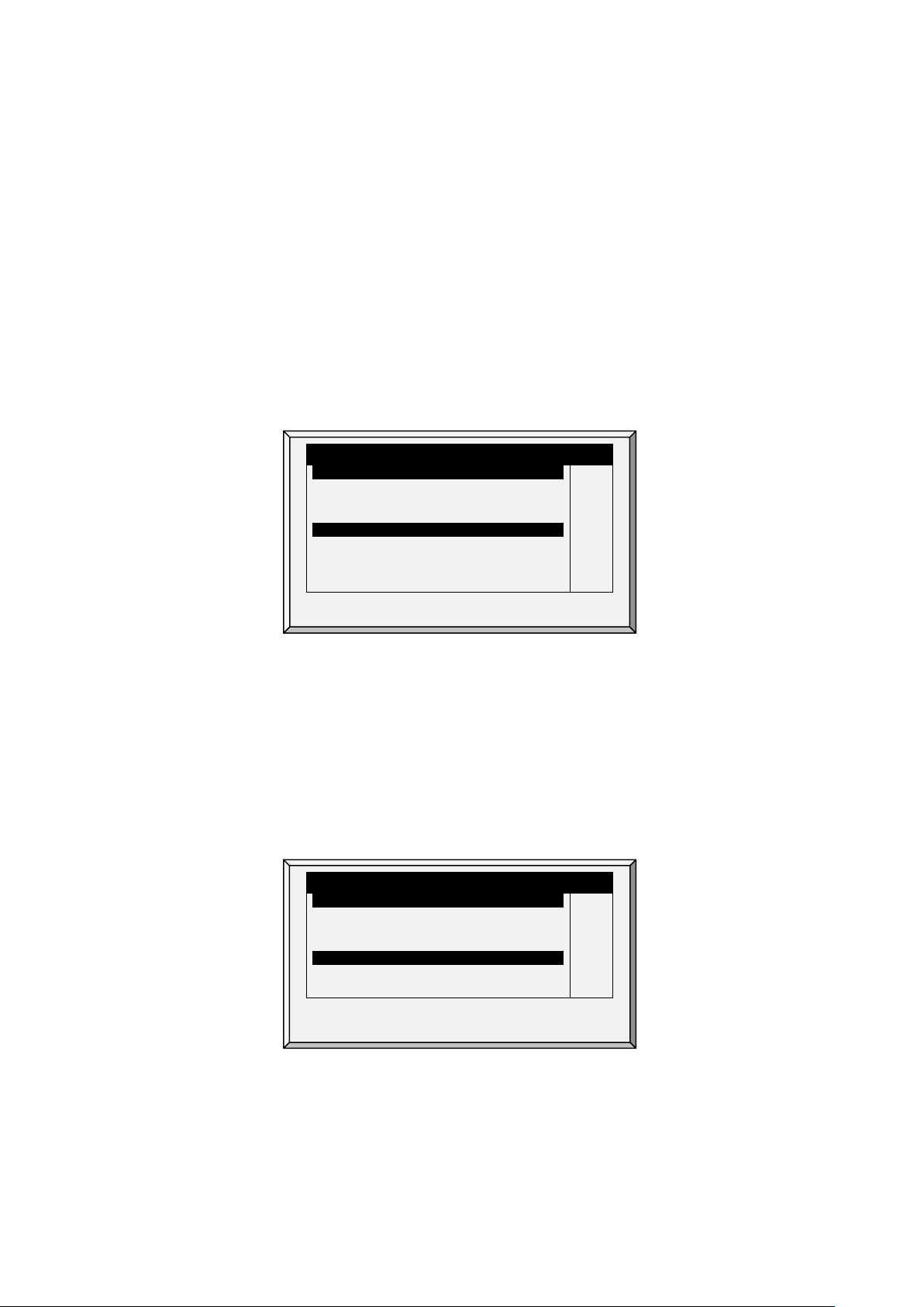
SYSTEM PARAMETERS
•
Define the parameters.
o
Difference Above Heat to Stop Heater: Differential from target temperature at which
the heater runs at minimal input
o
High Difference Below Heat: High Difference Below Heat: Temperature at which the
heater begins to operate at maximum output
o
Response Time (seconds): Amount of time before the controller begins to change the
ventilation.
3.1.4.3 Linear Valve
Rad. Low –Diff from Heat Set
Rad. High –Diff (Below Low Set)
Radiant Ignition Time (sec)
VARIABL E HEATER
Diff Above Heat to Stop Heater
High Diff Below Heat
Response Time (seconds)
SYSTEM PARAMETERS
Rad. Low –Diff from Heat Set
Rad. High –Diff (Below Low Set)
Radiant Ignition Time (sec)
VARIABL E HEATER
Low Diff Below Heat
High Diff Below Heat
0.0
1.0
30
1.0
8.0
0.0
1.0
30
1.0
Linear Valve enables defining that variable heater input voltage is always equal to or above the minimum
input defined in Installation > Analog Sensors..
When the Analog Heat Mode is defined as having Linear Valve control, there is always a minimal
voltage input. Therefore, if the minimum voltage is 1 volts:
© Munters AB, 2021 15
•
The voltage range is from 1 to 10 volts
o
this corresponds to 10% at 1V and 100% at 10V
Page 21
RADIANT HEATERS
High Diff Below Heat Tmp.
o
interpolation inside the band
•
There is 0% voltage when the target temperature is reached.
•
Define.
o
Difference Above Heat to Stop Heater: Differential from target temperature at which
the heater runs at minimal input
o
High Difference Below Heat: High Difference Below Heat: Temperature at which the
heater begins to operate at maximum output.
3.1.5 V
ARIABLE FLOOR HEATER | SET DEFINITIONS
SYSTEM PARAMETERS
Rad. Low –Diff from Heat Set
Rad. High –Diff (Below Low Set)
Radiant Ignition Time (sec)
VARIABL E HEATER
Low Diff Below Heat Tmp.
High Diff Below Heat Tmp.
VARIABLE FLOOR HEATER
Low Diff Below Heat Tmp.
0.0
1.0
30
0.5
4.5
0.5
4.5
AC-2000 3G Controllers enable configuring up to two variable floor heaters. The output of the heaters
changes as the temperature increases or decreases.
Install at least one analog output card.
To configure the variable floor heaters:
1. In
a. up to two analog outputs as variable heaters
b. the minimum and maximum voltage output for each heater
© Munters AB, 2021 16
Installation > Analog Output
configure:
Page 22

Output
Function
Min
V.Out
Max
V. Out
1
Var. Heater 1
1.0
10.0 2 Var. Heater 2
1.0
10.0
ANALOG OUTPUT
Out No.
2. In
Control > Temperature Curve > Help
, scroll down to Variable Floor Heater.
3. Set the response time (amount of time before the controller begins to change the ventilation).
4. Variable heat parameters are dependent on the mode employed.
o
Linear Heat
o
Proportional Heat
o
Linear Valve
3.2 Introduction to Humidity, Ammonia, and CO2 Treatment
AC-2000 3G provides various options to controlling the humidity, CO2, and ammonia levels.
•
None: No treatment is provided.
•
Level: Ventilation levels increase for a designated amount of time.
•
Tunnel or exhaust fan: A designated fan turns on for a designated amount of time. The amount
of air blown into the house is greater than that provided by an increase in ventilation level.
•
Increase in air / weight: The total amount of air that fans need to provide increases by a user
defined amount. Fan stay on until CO2, humidity, or ammonia levels fall to their defined levels.
This option is only available when using Minimum Ventilation by Weight.
•
Humidity treatment by heat: In cold air situations, heaters can be turned on to lower the
relative humidity.
If there is a contradiction between CO2, humidity, and ammonia treatments:
•
Ammonia treatment has priority over CO2 treatment.
•
C02 treatment has priority over humidity treatment.
•
Increase in air / weight has priority over other treatments.
•
Humidity treatment by heat takes priority over increasing the ventilation.
3.3 Humidity Treatment
Humidity treatment forces an increase in ventilation level when the humidity is too high. It holds the
increase for ‘Duration Seconds’, and checks back after ‘Interval Minutes’ for another increase. After the
duration, the ventilation level comes back down automatically.
© Munters AB, 2021 17
Page 23
Delay
(Min)
Duration
(sec.) 1 70
10
130
7
75 7 150
14
80 5 180
0 0 0
0
0 0 0
0
0 0 0
0
0 0 0
0
0 0 0
0
Humidity Band (%)
5.0
HUMIDITY TREATMENT BY HEATERS
Humidity Treatment by Heaters
Diff to Stop Treatment by Heaters
YES
3.6
HUMIDITY TREATMENT
Day Humidity
1. In
Install > Analog Sensors
(refer to Analog Sensors, page 81), designate up one or two sensors
as indoor humidity sensors (outdoor sensor is for information only). When using more than one
sensor, AC-2000 3G begins treatments based on the average.
2. If required, go to
Service > Humidity Calibration
Calibration, page 72).
3. In
Control > Humidity Treatment
o
Day: Growth day. Can set multiple programs for same day (maximum number of
programs: 20)
o
Humidity: Humidity at which to begin treatment
o
Delay Minute: Amount of time the controller pauses before ventilating
o
Duration Sec.: Number of seconds the controller maintains the increased level of
ventilation
4. Set the Humidity Sensor Alarm (page 55).
3.3.1 H
UMIDITY TREATMENT HELP | SET DEFINITIONS
While viewing the Humidity Treatment menu: Press HELP, select SET, and press ENTER.
Humidity Treatment below Heat
Humidity Treatment By
Outside Temp Treat by Heaters
, and calibrate the sensors (refer to CO2 Sensor
set the parameters as required.
HUMIDITY TREATMENT
YES
Exh 6
-18.0
• Define:
o
Humidity Band (%): Hysteresis band (delay) for Humidity Treatment.
o
Humidity Treatment below Heat: Select YES or NO for allowing Humidity Treatment
when heaters are operating (set in Temperature Curve).
o
Humidity Treatment By: This parameter designates the method used when humidity or
CO2 treatment begins. Normally, this parameter is relevant only when minimum
ventilation is running. When a treatment is required, select one the method to be
employed:
Level: Increases the ventilation level when a treatment is required.
NOTE When employing Ventilation by Weight, the controller increases the cycle time or the level,
depending on the particular settings.
Exhaust: Designate a specific exhaust fan (press a number key to select the fan).
© Munters AB, 2021 18
Page 24

Day
Start
Stop
Delay
Duration
Value
Value
(sec)
(sec)
1
0
3000
0
2500
0
120
0
130
0
Tunnel: Designate a specific tunnel (press a number key to select the fan).
None: Disables the treatment.
To enable the exhaust/tunnel options, in
Output
, designate at least one relay/variable device as a tunnel or exhaust fan.
o
Humidity Treatment by Heaters: This parameter enables using the heaters to lower the
Installation > Relay Outlet
or
Installation > Analog
relative humidity. If enabled, define:
Outside Temp Treat by Heaters: Heaters handle humidity treatment when the
outside temperature is lower than the target temperature by this amount.
Diff to Stop Treatment by Heaters: Heaters cease the humidity treatment if the
inside temperature is lower (or higher) than the target temperature by this amount.
This number can be positive or negative.
Humidity Treatment by Heaters requires designating at least one temperature sensor as an
outside sensor (refer to Temperature Definition, page 85).
NOTE If the heaters are operating because of the interior temperature, Humidity Treatment by Heaters
is disabled.
3.4 CO2 Treatment
CO2 treatment forces an increase in ventilation level when the CO2 level is too high. It holds the increase
for ‘Delay Seconds’, and checks back after ‘Interval Minutes’ for another increase. After the duration, the
ventilation level may come back down automatically. If during treatment, the CO2 level drops below the
Stop Value parameter, the ventilation level automatically returns to that level used before CO2 treatment
was initiated.
1. In
Install > Analog Sensors
sensor.
2. If required, go to
page 81).
3. In
Control > CO2 Treatment
o
Day: Growth day. Can set multiple programs for same day (Max. programs 20)
o
Start Value: CO2 value at which to begin treatment
o
Stop Value: CO2 value at which to end treatment
o
Delay (Sec): Number of seconds the controller pauses before ventilating
o
Duration (Sec): Number of seconds the controller maintains the increased level of
ventilation
CO2 TREATMENT
7
14
0
0
0
0
0
0
2700
2500
0
0
0
0
0
0
2200
2000
0
0
0
0
0
0
(refer to Analog Sensors, page 81), designate one sensor as a CO2
Service > CO2 Calibration
set the parameters as required.
120
90
0
0
0
0
0
0
150
180
0
0
0
0
0
0
, calibrate the sensors (refer to Analog Sensors,
4. Set the CO2 Sensor Alarm (page 55).
© Munters AB, 2021 19
Page 25

CO2 Treatment Below Heat
NO
CO2 Treatment By
Exh 6
CO2 TREATMENT BY HEATERS
CO2 Treatment by Heaters
YES
3.4.1
CO2 T
While viewing the CO2 Treatment menu: Press HELP, select SET, and press ENTER.
REATMENT HELP | SET DEFINITIONS
SYSTEM PARAMETERS
CO2 TREATMENT
Outside Temp Treat by Heaters
Diff to Stop Treatment by Heaters
•
CO2 Treatment below Heat: Select YES or NO to enable CO2 treatment when heaters are
-18.0
3.6
operating (set in Control | Temperature Curve).
•
CO2 Treatment By: This parameter designates the method used when humidity or CO2
treatment begins. Normally, this parameter is relevant only when minimum ventilation is
running. When a treatment is required, select one the method to be employed:
o
Level: Increases the ventilation level when a treatment is required.
NOTE When employing Ventilation by Weight (refer to page 22), the controller increases the cycle
time or the level, depending on the particular settings.
o
Exhaust: Designate a specific exhaust fan (press a number key to select the fan).
o
Tunnel: Designate a specific tunnel (press a number key to select the fan).
o
None: Disables the treatment.
To enable the exhaust/tunnel options, in
Output
, designate a relay/variable device as a tunnel or exhaust fan.
o
CO2 Treatment by Heaters: This parameter enables running the heaters in situations
Installation > Relay Outlet
or
Installation > Analog
where the CO2 level is high. Typically this can happen in cold temperatures when CO2
is produced by the heaters. By increasing the heat in the house, ventilation can then be
increased. If enabled, define:
Outside Temp Treat by Heaters: Heaters handle CO2 treatment when the outside
temperature is lower than the target temperature by this amount.
Diff to Stop Treatment by Heaters: Heaters cease the CO2 treatment if the inside
temperature is lower (or higher) than the target temperature by this amount. This
number can be positive or negative.
CO2 Treatment by Heater requires designating at least one temperature sensor as an
outside sensor (refer to Temperature Definition, page 85).
NOTE If the heaters are operating because of the interior temperature only, CO2 Treatment by Heater
is disabled.
3.5 Min/Max Level
IMPORTANT: Before setting Min/Max levels, go through and set up the Device Settings,
especially the ventilation levels.
Once you have entered the ventilation levels, use Min/Max to select the range of levels to apply to your
situation. Typically, you increase the minimum ventilation level as litter conditions deteriorate and the
© Munters AB, 2021 20
Page 26
Day
Min
Max
1
0
1
0
16
0 MIN/MAX LEVEL
From
Min
Max
06:00
00:00
1
0
6
0
birds require greater amounts of fresh air. You can also restrict the maximum level to prevent excess
airflow on young birds.
Use one of the following methods to set the Min/Max levels:
•
By Day and By Soft Days Curve
•
By Time
•
Day Soft Min.
By Weight
•
Before configuring these parameters, go to
28) to select the required method.
3.5.1 BY D
AY AND BY SOFT DAYS CURVE
•
Day: Set growth day
•
Min: Set the controller's minimum ventilation level
•
Max: Set the controller's maximum ventilation level
o
BY DAYS CURVE generates an incremental increase/decrease between the defined
days.
o
BY DAYS operates according to that day's values until the next defined day is reached.
Control Mode > Min. Max. Level Control
MIN/MAX LEVEL
3
6
10
14
21
35
0
0
2
3
4
5
6
7
0
0
16
16
16
21
21
21
0
0
(page
3.5.2 BY T
© Munters AB, 2021 21
IME
10:00
13:00
18:00
21:00
00:00
00:00
00:00
00:00
•
From: Set time of day (hh:mm) in 24 hour format
•
Min: Set minimum ventilation level for controller
•
Max: Set maximum ventilation level for controller
4
8
6
12
8
15
1
3
0
0
0
0
0
0
0
0
Page 27
Day
Min
Soft
Min
Max
11
SYSTEM PARAMETERS
SOFT MIN/MAX LEVEL
Temp Choice for Soft Min.
ATTIC
3.5.3 D
AY SOFT MIN
•
Day: Set growth day
•
Min Soft: Set minimum ventilation level for when temperature drops below heat temperature
•
Min: Set minimum ventilation level for when temperature is above heat temperature
•
Max: Set maximum ventilation level for controller
.
SOFT MIN/MAX LEVEL
1
3
6
10
14
21
35
0
0
0
1
11
2
11
3
11
4
11
5
11
6
11
7
0
0
0
0
0
0
3.5.3.1 Soft Min/Max Level Help | Set Definitions
While viewing the Soft Min/Max Level menu: Press HELP, select SET, and press ENTER.
16
16
16
16
21
21
21
0
0
0
Diff. Below Heat for Soft Min.
10.0
•
Differential Below Heat for Soft Min: Set the degree of difference from heat temperature (set
in Control | Temperature Curve) to switch minimum level from Min. to Soft Min.
Temp Choice for Soft Min: Select inside/outside/attic temperature to control Minimum Level
•
changes. The minimum level adjusts towards the Soft Min as this temperature falls. Above the
heat temperature, the minimum level is at the Min setting.
As temperature rises, INSIDE and ATTIC stay at lowest ventilation level reached until average
temperature gets to the heat setting, and then changes instantly. With the OUTSIDE selection, the
minimum ventilation level increases gradually as temperature rises to the heat setting. This means inside
and attic soft min vent choices to latch to the lowest level reached as long as the temperature remains
below the heat setting.
3.5.4 BY W
EIGHT
The By Weight option enables controlling the minimum air flow depending on the number of birds, their
weight and the current outside temperature. When using the Weight option, AC-2000 3G takes several
parameters and calculates the air speed, level of ventilation and cycle time needed to supply the required
volume. As opposed to the other ventilation methods, the Weight option is dynamic, with the ventilation
changing according to the current parameters (quantity of air required, weight of birds and number of
birds, outside air temperature). In addition, Ventilation By Weight sends out an alarm if the current
ventilation is below the minimum required level.
To set up the Weight Option:
1. In
Install > Setup
© Munters AB, 2021 22
(page 79) enable Minimum Vent (Power).
Page 28
Day
Min
Level
Air Per Kg/Lb
Max
Level
Cold
Warm
1
350
1
70
0.5
0
1.5
1.7
16
22
2. In
Install > Fan Air Capacity
3. In
Management > Bird Inventory
4. In
Scale> General Setting
5. In
Scale > Bird Curve
6. In
Control > Control Mode
7. In
Control > Min/Max Level
, define the air capacity / hour (page 86).
, define the number of birds.
, select the curve.
, define the growth days and weights as required.
>
Min. Max Level Control
, select Weight.
, set the parameters as required.
SOFT MIN/MAX LEVEL BY WEIGHT (OUT TEMP)
3
6
10
12
15
17
19
21
o
Day: Set growth day
o
Min Level: Set the minimum level of ventilation (refer to Levels of Ventilation, page 33)
o
Air Per Kg/Lb: Volume of air per kilogram/pound per hour per bird.
Cold: Volume of air supplied when the outside temperature goes down to the
Temperature
parameter (see the following section).
Warm: Volume of air supplied when the outside temperature reaches
– Diff Below Heat
1
1
4
4
7
7
7
7
0.5
0.5
1.1
1.1
1.1
1.1
1.1
1.1
1.5
1.5
1.7
1.7
1.7
1.7
1.7
1.7
16
16
16
21
21
21
21
21
(see the following section).
Cold
Warm Temp.
NOTE As the level rises between days (for example between day 6 and day 10 in the screen above),
the air volume rises proportionally each day, once a day. For example, on Day 7, the Cold Air
per Kg/Lb. rises to 0.65; on Day 8, 0.8 and so on.
o
Max Level: Set the maximum level of ventilation (refer to Levels of Ventilation, page 33).
8. In the
Management > Bird Inventory
menu, type the number of birds.
9. In the Help menu, define the parameters as required.
Ventilation by Weight is configured.
• Min/Max Level By Weight Help | Set Definitions, Version 9.18 and Below
• Min/Max Level By Weight Help | Set Definitions Version 9.19
• Weight Hot Screen
© Munters AB, 2021 23
Page 29

SOFT MIN/MAX LEVEL BY WEIGHT
Air Per Weight Curve Mode
2
3.5.4.1 Min/Max Level By Weight Help | Set Definitions, Version 9.18 and Below
While viewing the Min/Max Level by Weight menu: Press HELP, select SET and press ENTER.
SYSTEM PARAMETERS
Warm Temp. – Diff Below Heat
Cold Temperature
Air Change
Fan Cycle Time (sec, 0 – Manual)
Minimum ON Time in Vent Cycl e
Minimum OFF Time Vent Cycle
Air Change by Humidity/CO2 %
•
Warm Temperature – Difference Below Heat: Differential below the heat temperature (refer
2.0
68.0
0.24
600
60
60
20
to Temperature Curve, page 9) that defines outside temperature as Warm in the Soft Min/Max
table. For example, if the Heat Temperature is 78° F, Warm Temp. – Diff Below Heat is 2.0,
than the outside temperature is defined as warm at 76° F.
•
Cold Temperature: Outside temperature (or below) at which Air per Kg/Lb (Cold) capacity
is reached.
When the outside temperature is between the Warm and Cold Temperature, the flow rate is
calculated at a proportional rate.
•
Air Change: As the temperature rises from the Cold Temperature parameter to the Heat
Temperature (or drops from the Heat Temperature to the Cold Temperature parameter), the
minimal air volume rises/falls proportionally. Air Change defines the minimal change in air
temperature that must takes place to cause a change in the air supply.
•
Fan Cycle Time: The total amount of time that the fans operate while operating under Minimum
Ventilation. During this time, the fans supply the required volume of air at the minimum
ventilation level required. AC-2000 3G adjusts the minimum ON time and OFF time as
needed. If the fans cannot supply the required volume at a particular level of ventilation, the
controller automatically adjusts the minimum ventilation level.
o
Minimum ON Time in Vent Cycle: The minimum amount of time that the fans operate
during a cycle. The controller adjusts the actual fan time as needed.
o
Minimum OFF Time in Vent Cycle: The minimum amount of time that the fans do not
operate during a cycle. The controller adjusts the actual fan time as needed.
As the temperature rises, the actual Minimum OFF Time decreases until it reaches the minimum time.
Only then does the Minimum On Time begin to rise.
NOTE If the temperature goes above the Band Temperature, Power Ventilation begins and times are
adjusted accordingly.
•
Air Change By Humidity/CO2/Ammon%: As the humidity, CO2, or ammonia levels rise
above the levels specified in Humidity Treatment, CO2 Treatment, or Ammonia Treatment the
minimal air volume rises proportionally. Air Change By Humidity/CO2/Ammon% defines the
minimal change in in these levels that must take place to cause an increase in the air supply.
•
Air Per Weight Curve Mode: By default, Air per Kilo/Lb has two data points: cold
temperature and warm. If desired, the user can add an additional intermediate (computer
defined) data point which is between the two default points. This point determines the quantity
of air to be distributed when the temperature reaches the midpoint between the cold and warm
© Munters AB, 2021 24
temperatures.
Page 30
SOFT MIN/MAX LEVEL BY WEIGHT (OUT TEMP)
Day
Min
Level
Air Per Kg/Lb
Max
Level
Cold Warm
1
35
1
7
0.5
0
0.9
1.4
1.5
1.7
16
22
SOFT MIN/MAX LEVEL BY WEIGHT
Air Per Weight Curve Mode
3
3
6
10
12
15
17
19
21
1
1
4
4
7
7
7
7
0.5
0.5
1.1
1.1
1.1
1.1
1.1
1.1
0.9
0.9
1.4
1.4
1.4
1.4
1.4
1.4
1.5
1.5
1.7
1.7
1.7
1.7
1.7
1.7
16
16
16
21
21
21
21
21
NOTE In a three point curve, the intermediate value must be between the cold and warm value in each
line.
3.5.4.2 Min/Max Level By Weight Help | Set Definitions Version 9.19
Version 9.19 has an additional parameter, Medium Temp, which enables setting up a more accurate
temperature curve in Air by Weight. By default, the curve is determined by the Air per Kg/Lb Cold and
Warm Temperatures. Medium Temp adds an additional (user-defined) point to the curve.
To add the Medium Temp point:
1. Configure Air by Weight as shown in By Weight, page 22.
2. Go to Control > Min/Max > Help and configure the parameters (refer to Min/Max Level By
Weight Help | Set Definitions, Version 9.18 and Below, page 24 for details).
3. In the Help screen, define the Air per Weight Curve Mode:
•
Using the number pad keys to define the mode as 2 or 3.
o
If set to 2, the Medium Temp parameter is disabled.
o
If set to 3, define the Medium Temp parameter.
SYSTEM PARAMETERS
Warm Temp. – Diff Below Heat
Medium Temp
Cold Temperature
Air Change
Fan Cycle Time (sec, 0 – Manual)
Minimum ON Time in Vent Cycle
Minimum OFF Time Vent Cycle
Air Change by Humidity/CO2/Ammon% %
2.0
72.0
68.0
0.24
600
60
60
20
It can be no lower than the Cold Temperature.
It can be no higher than the Warm Temperature minus Warm Temp. –Diff below
Heat differential.
Go to the Control Menu screen, re-enter the Mini/Max screen, and the Medium
Weight parameter appears.
© Munters AB, 2021 25
Page 31

SOFT MIN/MAX LEVEL BY WEIGHT (OUT TEMP)
Day
Min
Level
Air Per Kg/Lb
Max
Level
Cold
Med
Warm
1
35
1
7
0.5
0
0.9
1.4
1.5
1.7
16
22
AIR STATUS
Inside Temp
Weight KG
24.1
0.468
Current
Min
Max
Level
2 1 2 Cycle On
30
30
30
Cycle Off
98
134
66
Total Air
M3/h
M3/h
8347
6552
11232
Air/WGT
M3h/kg
0.9
0.7
1.20
3
6
10
12
15
17
19
21
1
1
4
4
7
7
7
7
0.5
0.5
1.1
1.1
1.1
1.1
1.1
1.1
0.9
0.9
1.4
1.4
1.4
1.4
1.4
1.4
1.5
1.5
1.7
1.7
1.7
1.7
1.7
1.7
16
16
16
21
21
21
21
21
3.5.4.3 Weight Hot Screen
Selecting the Ventilation by Weight option enables an additional Hot Screen, the Air Status Screen. This
screen displays the critical parameters involved in the Ventilation by Weight option.
Outside Temp
Humidity
21.3
46.7%
•
Inside Temperature: Current temperature inside the house
•
Outside Temperature: Current temperature outside the house
•
Humidity: Current relative humidity inside the house (requires a humidity sensor)
•
Weight KG: Current average weight of the Bird Curve (page 59)
•
Level: Displays the current, minimum and maximum level of ventilation.
NOTE If the current level is below the minimum required level, AC-2000 3G displays an alarm “Below
Min Air”.
•
Cycle On/Off: Displays the current, minimum and maximum fan on and off times.
•
Total Air M3/h: Displays the current, minimum and maximum quantity of ventilation, per hour.
•
Air/WGT: Displays the current amount of ventilation, per kilo/pound of bird weight.
© Munters AB, 2021 26
Page 32

Target Static Pressure
3.6 Static Pressure
This screen sets target parameters for Static Pressure at High and Low Outside Temperatures, as well as
alarms for high and low static pressure.
STATIC PRESSURE
Minimum Ventilation
S.Press. At Low Temperature
S.Press. At High Temperature
Low Static Pressure Alarm
High Static Pressure Alarm
Static Pressure Band
Target Static Pressure
Low Static Pressure Alarm
High Static Pressure Alarm
Static Pressure Band
•
Disabling the Static Pressure Sensor
•
Static Pressure Help | Set Definitions
•
Multi Stage Tunnel Curtains
Tunnel Ventilation
Atti c
0.120
0.080
0.010
0.150
0.040
0.080
0.010
0.150
0.040
0.050
Minimum Ventilation
•
Static Pressure at Low Temp: Set desired static pressure for low outside temperature conditions.
Be sure that there is proper airflow at this setting.
•
Static Pressure at High Temp: Set desired static pressure for high temperature conditions.
Normally this pressure is lower to obtain a larger air inlet opening.
NOTE The controller interpolates between the LOW and HIGH Temperatures. If Static Pressure exists, it
is controlled by the outside temperature sensor or the average temperature (if there is no
sensor).
•
Low Static Pressure Alarm: Set alarm for low static pressure. If you disable it by setting zero, the
AC-2000 3G warns you and enters a record in the Table of Events.
•
High Static Pressure Alarm: Set alarm for high static pressure.
•
Static Pressure Band: Set desired band for the target pressure.
Tunnel Ventilation
•
Target Static Pressure: Set required Static Pressure for Tunnel Ventilation Mode.
•
Low Static Pressure Alarm: Set alarm for low static pressure.
•
High Static Pressure Alarm: Set alarm for high static pressure.
•
Static Pressure Band: Set required band for pressure in tunnel ventilation mode.
3.6.1 D
© Munters AB, 2021 27
Attic
•
Target Static Pressure: Set required Static Pressure when in attic mode.
•
Static Pressure Band: Set required band for attic ventilation mode.
ISABLING THE STATIC PRESSURE SENSOR
To disable the static pressure sensor:
1. Go to
Installation > Setup
.
Page 33

STATIC PRESSURE
Attic Advance Opening Time (sec)
0
2. Set the Static Pressure Unit to None.
The main screen stops:
o
displaying the pressure
o
displaying High Pressure and Pressure Sensor Failure alarms
If either of these alarms were active before disabling the sensor, the main screen continues to
display the alarms. Reset the alarms one time to cease the display.
3.6.2 S
TATIC PRESSURE HELP | SET DEFINITIONS
While viewing the Static Pressure menu: Press HELP, select SET, and press ENTER.
SYSTEM PARAMETERS
Wind Gust Delay Time (sec)
S. Pressure During Tunnel
Transitional Tunnel
Minimum Ventilation Using
Low Incoming Air (diff to Trg)
High Incoming Air (diff to Trg)
Emergency S. Press. Delay (sec)
Curt. Pos. In Emerg. S. Press.%
Low S.P. Alarm Min. Level (MinV)
Low S.P. Alarm Min. Level (Tun.)
Time To Produce S. Pressure (sec)
•
Wind Gust Delay Time (sec): Set length of time in seconds before starting Static Pressure
10
YES
NO
VENT
-25.0
-10.0
60
100
0
0
10
control after an unexpected change in air pressure.
•
Static Pressure During Tunnel: Select YES or NO for using Static Pressure control when in
Tunnel mode.
•
Transitional Tunnel: Select YES or NO for using tunnel curtains when static pressure is high
and vents are already at 100%.
•
Minimum Ventilation Using (vent/curtain): Select VENT or CURTAIN for controlling static
pressure when in minimum ventilation.
•
Low Incoming Air (Diff to Trigger): Define low temperature for static pressure control.
•
High Incoming Air (Diff to Trigger): Define high temperature for static pressure control.
•
Emergency Static Pressure Delay (sec): Set length of time in seconds before initiating an
emergency opening when pressure exceeds high alarm setting.
•
Curtain Position in Emergency Static Pressure (%): Set the desired curtain position (in
percentage) when an emergency pressure event occurs.
•
Low Static Pressure Alarm Min. Level (MinV): Below this level, the controller ignores low
static pressure alarms.
•
Low Static Pressure Alarm Min. Level (Tun.): Below this level, the controller ignores low static
pressure alarms while in tunnel mode.
•
Time to Produce Static Pressure (sec): Enter the length of time to reach target pressure when
minimum ventilation fan cycle is on.
•
Attic Advance Opening Time (sec): Define the amount of time for the attic inlets to open
before minimum vent cycling fans turn on.
3.6.3 M
ULTI STAGE TUNNEL CURTAINS
When in static pressure mode and employing multiple tunnel curtains, AC-2000 3G can open the curtains
in sequence. Opening the tunnel curtains commences when the target static pressure is reached and the
© Munters AB, 2021 28
Page 34

Page
System Parameters
House Mode
Analog Heat Mode
FULL
LINE AR
controller signals to the tunnel machine to operate the curtains. AC-2000 3G opens the first tunnel
curtain (as defined in the relays) to the user defined level. If additional ventilation is required, the second
tunnel curtain opens. This process continues for each defined curtain.
As pressure falls, the process is reversed; curtains close in progression starting with the last curtain.
To set up Multi Stage Tunnel Curtains:
1. In
Installation > Relays
2. In
Device > Vent & Curtain Levels
3. In
Static Pressure > Tunnel Ventilation
define more than one relay as tunnel curtain (open and close).
, define the opening levels for each curtain.
, define the target pressure.
3.7 Control Mode
Select house-operating modes, turn temperature curves on or off and select which type of min/max CO2
level method to use.
CONTROL MODE
Empty House Mode
Temperature Curve
Min. Max. Level Control
Heat Cycle
•
House Mode: Select whether the house is in one of the brood set ups, or in full house.
•
Empty House Mode: Select YES in order to disable alarms.
•
Temperature Curve: If you select OFF, temperature settings become fixed values until midnight
HOUSE
HOUSE
BY WEIGHT
NO
on the next setting in Control | Temperature Curve (page 9).
•
Min. Max. Level Control: Set ventilation control method (By Days, By Days Curve, By Time, By
Soft Min, and Weight). Refer to Min/Max Level, page 20 for more details).
•
Heat Cycle: Enable cycle heaters. Refer to Cycle Heaters | Set Definitions, page 12.
•
Analog Heat Mode: Define the variable heating mode (Linear, Proportional, Linear Valve).
Refer to Variable Heater Help | Set Definitions, page 13.
3.8 System Parameters
System Parameters consolidates all of the HELP | SET menus into one screen.
© Munters AB, 2021 29
9 Temperature Curve
11 Radiant Heaters Help | Set Definitions
19 CO2 Treatment Help | Set Definitions
27 Static Pressure Help | Set Definitions
34 Levels of Ventilation Help | Set Definitions
37 Curtains
84 Vent/Curtain Help | Set Definitions
27 Attic
Page 35

Page
System Parameters
AMMONIA TREATMENT
Day
Start
Stop
Delay
Duration
Value
Value
(Sec)
Sec.
1
0
25
25
10
10
120
0
130
0
41 Cool Pad Help | Set Definitions
41 Cool Pad Flush
42 Foggers Help | Set Definitions
44 Light Help | Set Definitions
46 Water and Feed Help | Set Definitions
51 Feed Inventory Help | Set Definitions
54 Alarm Setting Help | Set Definitions
3.9 Ammonia Treatment
Ammonia treatment forces an increase in ventilation level when the ammonia level is too high. To prevent
fans changing their ventilation too often, treatment begins after a user-defined delay. The user also
defines the treatment duration.
After the treatment, the ventilation level may come back down automatically if the house temperature is
below the target temperature. Otherwise, the ventilation level does not change. If during treatment, the
ammonia level drops below the Stop Value parameter, the ventilation level automatically returns to that
level used before ammonia treatment began.
7
14
0
0
0
0
0
0
This function requires an ammonia sensor.
1. In
Install > Analog Sensors
25
25
25
25
25
25
25
25
10
10
10
10
10
10
10
10
120
90
0
0
0
0
0
0
150
180
0
0
0
0
0
0
(refer to Analog Sensors), designate one sensor as an ammonia
sensor.
2. If required, go to
3. In
Control > Ammonia Treatment
o
Day: Growth day. You can set multiple programs for same day (maximum number of
Service > Ammonia
set the parameters.
and calibrate the sensors (refer to Ammonia Calibration).
programs: 20)
o
Start Value: Ammonia value at which to begin treatment. Range: 0 to 100. Default: 2
NOTE Ammonia levels should not be higher than 30 ppm.
© Munters AB, 2021 30
o
Stop Value: Ammonia value at which to end treatment. Range: 0 to 100. Default: 2. The
stop value must be lower than the start value.
o
Delay (Sec): When the ammonia level reaches the start value, the controller delays
treatment for this amount of time. Default: 0
Page 36

SYSTEM PARAMETERS
Ammonia Treatment By
o
Duration (Sec): Number of seconds the controller maintains the increased level of
ventilation. Default: 0
4. Set the Ammonia Alarm (page 55).
3.9.1 A
MMONIA TREATMENT HELP | SET DEFINITIONS
While viewing the Ammonia Treatment menu: Press HELP, select SET, and press ENTER.
AMMONIA TREATMENT
Ammonia Treatment Below Heat
o
Ammonia Treatment below Heat: Select: Select YES or NO to enable Ammonia
No
Level
Treatment when heaters are operating (set in Temperature Curve).
o
Ammonia Treatment By: This parameter designates the method used when ammonia
treatment begins. Normally, this parameter is relevant only when minimum ventilation is
running. When a treatment is required, select the method to be employed:
Level: Increases the ventilation level when a treatment is required.
NOTE When employing Ventilation by Weight, the controller increases the cycle time or the level,
depending on the particular settings.
Exhaust: Designate a specific exhaust fan (press a number key to select the fan).
Tunnel: Designate a specific tunnel fan (press a number key to select the fan).
None: Disables the treatment.
© Munters AB, 2021 31
Page 37

Levels of Ventilation, page
DEVICE SETTING
4 Device Menu
The AC-2000 3G can have many closely spaced levels of ventilation enabling it to find the optimum
average airflow for the poultry facility. Many of the levels are at exactly the same temperature setting, so
there may be a question as to how the AC-2000 3G chooses the correct level. The menus in this section
apply levels to ventilation, variable speed fans, curtains, and so on. The levels in the various menus are
consistent with each other so that a level in one menu corresponds with that level in any other menu.
The rules that apply here are:
•
Rule 1: If the temperature is at target (in the Happy Zone) stay at the current level.
•
Rule 2: If the temperature moves outside the Happy Zone wait for a few minutes.
Rule 3: After waiting increase or decrease level appropriately.
•
You can find the ‘patience’ factors under HELP | SET in this menu. They are the increase level delay and
decrease level delay parameters. The factory default values are 180 seconds for an increase and 60
seconds for a decrease. The factory default values biases the AC-2000 3G slightly toward warmer
temperatures, as would be appropriate for young birds. The level increase delay is longer than the level
decrease delay. You may wish to reverse these values by the time you have market age broilers, since
they are more sensitive to heat stress than to cold.
Although many of the levels have 0.0 differential temperatures, certain levels should have differentials to
account for wind chill on the birds. The first tunnel level accounts for wind chill by switching to the tunnel
temperature instead of target temperature. Higher tunnel levels require an additional wind chill because
of the increased airflow.
In addition, the last few levels before entering tunnel can form a transitional region. You may want to
build differentials from target temperature just before the first tunnel level.
The controller obeys both the time delay rules and the differential temperature rules when changing levels.
Tunnel exit has several additional rules, such as outside temperature restriction and the tunnel exit delay
described under HELP | SET. In addition, there are Cool Down and change to Min Vent on reaching the
Heat temperature features described in Control | Temperature Curve | HELP | Set parameters.
The following sections detail the menu functions.
•
33
•
Variable Speed Fan Levels, page 35
•
Vent & Curtain Levels, page
36
•
Stir Fan Levels, page 37
•
Stir Fan Program, page
38
•
Cool Pad, page 40
1. LEVELS OF VENTILATION
2. SPEED FAN LEVELS
3. VENT & CURTAIN LEVELS
4. STIR FAN LEVELS
5. STIR FAN PROGRAM
6. COOL PAD
7. FOGGERS
8. LIGHT
9. WATER & FEED
10. EXTRA SYSTEMS
11. WATER ON DEMAND
© Munters AB, 2021 32
Page 38

LEVELS OF VENTILATION
No
Diff
On
Exhaust
Tunnel
Deg.
Sec
1 2 3
1 2 3
1
16
0.0
0.0
30
0
Tunnel Level: T
•
Foggers, page
42
•
Light, page 43
•
Water & Feed, page
45
•
Extra Systems, page 47
•
Water on Demand, page 47
4.1 Levels of Ventilation
The Ventilation table provides up to 30 ventilation levels. To program this table, start with the minimum
ventilation used in the first level and increase ventilation gradually. A reasonable rule of thumb is to
increase the airflow about 25% at each level. Increases in airflow up to 50% work satisfactorily with
factory default settings.
1. Do one or both:
o
In
Install > Relay Outlet
Fan or Exhaust Fan.
o
In
Install > Analog Output
Fan or Exhaust Fan.
(refer to page Relay Layout) define at least one relay as a Tunnel
(refer to page Analog Sensors) define one function as Tunnel
2. In
Device Setting > Levels of Ventilation
3. Configure the Help Set parameters as required.
0.0.
Air Capacity: 300 -Continuous
Chill Range: --- -Cycle
-Rotate
NOTE The number appearing under Exhaust and Tunnel is refers to the numbers defined in Installation.
•
Number: Read-only showing the ventilation level.
NOTE At the First Tunnel Level (defined in the Help | Set Definitions) the screen displays the tunnel
temperature (defined in Temperature Curve). T means the level is in tunnel mode.
© Munters AB, 2021 33
2
3
4
5
6
7
8
9
10
11
12
13
14
15
0.0
0.0
0.0
0.0
0.0
0.0
0.0
0.0
0.0
0.0
0.0
0.0
0.0
0.0
45
60
80
120
160
200
250
100
120
150
180
0
150
0
configure the parameters as required.
Page 39

Continuous:
Rotate:
Cycle:
SYSTEM PARAMETERS
LEVELS OF VENTILATION
RH Effect
0.5
•
Differential Temperature: Triggers next level according to difference from target temperature
(time delays remain in effect).
o
The first several levels normally have differential temperature set to 0.
o
If the ventilation level is below tunnel, the differential temperature is relative to Target
temperature given in Control | Temperature Curve.
o
If the ventilation level is a tunnel level, the differential temperature is relative to the Tunnel
temperature given in Control | Temperature Curve.
•
Cycle timer ON: Set ON time for fans for that ventilation level.
•
Cycle timer OFF: Set OFF time for fans of that ventilation level. This parameter disappears if
cycle time is set in the HELP | SET Parameters to something other than 0 and the controller
calculates the “Cycle timer OFF” automatically.
•
Exhaust: Control exhaust fans according to Continuous, Cycle, and Rotate.
•
Tunnel: Control tunnel fans according to Continuous, Cycle, and Rotate.
•
Air Capacity: Displays the current exhaust fan or tunnel air flow for each ventilation level. If
Variable Speed Fan Levels have been set (refer to page 35), the speed percentage is taken
into account.
4.1.1 L
EVELS OF VENTILATION HELP | SET DEFINITIONS
When viewing the Levels of Ventilation menu: Press Help, select Set, and press Enter
•
•
•
•
•
•
•
Works
constantly without a break
Operates according to ON/OFF timer
timer; in each cycle a different fan operates
Operates according to ON/OFF
Maximum Levels of Ventilation
First Tunnel Level
Max Fans, Switch to Tunnel
Tunnel Exit – Diff Below Tunnel
Tun Exit-Out T. Diff from Tun.
Increase Level Delay Time (sec)
Decrease Level Delay Time (sec)
Fan Cycle Time (sec, 0-Manual)
Tunnel Exit Delay (minutes
Wind Chill Enable
Wind Chill Limit
Maximum Levels of Ventilation: Set the maximum number of levels.
First Tunnel Level: Entry point to tunnel mode.
Max Fans, Switch to Tunnel: Maximum number of fans allowed to operate when entering
tunnel mode.
Tunnel Exit – Differential Below Tunnel: Set degree of difference below Tunnel temperature
(set in Control | Temperature Curve) to Exit Tunnel mode.
Tunnel Exit – Outside Differential from Tunnel: The outside temperature must read below this
(Tunnel + Differential) to allow exiting from tunnel mode.
Increase Level Delay Time (sec): Set length of time in seconds before transitioning to next
level.
Decrease Level Delay Time (sec): Set length of time in seconds before transitioning to lower
level.
22
13
20
2.0
9.0
120
90
0
2
NO
14.4
© Munters AB, 2021 34
Page 40

•
Fan Cycle Time (sec): If set to 0, set on and off times for each level manually. If you are using
a fixed cycle time, such as 300 seconds, enter it here and enter only the On time at each level.
Default: 0
•
Tunnel Exit Delay (minutes): Set length of time in minutes before exiting Tunnel mode. This
time begins once all other parameters are satisfied.
•
Wind Chill: Refer to the following section.
4.1.2 W
IND CHILL
AC-2000 3G can take into consideration the wind chill factor when making certain calculations related to
the temperature. In effect, the wind chill factor acts as the temperature differential. When enabled, AC2000 3G determines the “calculated temperature (actual temperature – wind chill temperature) and uses
this temperature:
•
When calculating the Tunnel Mode level up/down algorithms
•
When operating the Cool Pad (if enabled in System Variables; refer to Operate Cool Pad,
page 40.
The Wind Chill factor influences controller operation from the 1st tunnel level.
NOTE The actual temperature: 1) determines the entry and exit into Tunnel Mode 2) controls the
fogger.
Parameters:
•
Wind Chill: Enable this parameter to include the wind chill factor in ventilation calculations.
Default = No.
•
Wind Chill Limit: Maximum wind chill factor value. Default = 8° C.
•
RH Effect: The decrease in temperature caused by an increase in relative humidity. Default is
0.26° C.
The Relative Humidity Effect parameter enables including the relative humidity (RH) in the wind chill factor
calculations. A rise in relative humidity reduces the wind chill factor. How does it work?
o
There is no effect below 40% relative humidity.
o
The user determines the increase in temperature for every 5% increase in relative
humidity.
The default increase is 0.26° C; meaning that between 40.1% - 45% relative
humidity, the wind chill factor decreases by 0.26° C. Between 45.1% - 50%, the
wind chill factor decreases by 0.52° C, twice the default level. Between 50.1% 55%, the decrease is 0.78° C, three times the default level, and so on.
The user can set the temperature increase as required.
To disable this feature, enter '0'
4.2 Variable Speed Fan Levels
In the Variable Speed Fan Level table set the speed in percentages for up to two groups of fans by level.
Several kinds of speed controllers are supported, such as TRIAC Control and Variable Frequency 3 Phase
drives.
© Munters AB, 2021 35
Page 41

VARIABLE SPEED FAN LEVEL
Tun 2 Exh 2 Exh
3
1
10 T
----
100
30
90
30
100
Level
Atti c
Vent
1
10
0
0
15
15
15
15
Level
1. In
Install > Analog Output
2
3
4
5 T
6 T
7 T
8 T
9 T
(refer to Analog Output, page 83), define at least one output as a
----
---45
45
60
60
75
90
30
30
45
60
60
75
75
90
30
45
45
45
60
60
75
90
variable speed fan.
2. In
Device Setting > Levels of Ventilation
, define the mode (required!).
NOTE "----" appears when the mode is undefined.
3. In
Device Setting > V. Speed Fan Levels
, define the fans' working percentages.
4.3 Vent & Curtain Levels
Set the curtain levels to correspond with the ventilation levels. The operating mode determines the curtain
control procedure.
Before configuring these parameters, define at least two relays as a vent open/vent close,
tunnel open/tunnel close, or attic open/attic close. Refer to Relay Layout, page 80.
VENT & CURTAIN LEVELS
Tunnel
2
3
4
5
6
7
8
9
0
0
0
0
0
0
0
0
15
15
15
15
15
15
15
15
15
15
15
15
15
15
15
15
NOTE Before setting the levels, define the opening mechanism (refer to Vent/Curtain Setup, page 83).
1. In
Install > Relay Outlet
(refer to page 80), define at least one relay as Curtain Open, Tunnel
Open, Vent Open, or Attic Open.
2. In
Control > Temperature curve
3. In
Device Setting > Vent & Curtain Levels
, define the Target Temperature.
, define the minimum opening percentages.
4. Press Enter.
5. If required, configure each opening to work with a particular temperature sensor. Refer to
Temperature Definition, page 85.
6. Set the Help Set parameters as required.
© Munters AB, 2021 36
o
Ventilation Level: Read-only.
Page 42

CURTAINS
Max Temperatur to Disable Attic
100.0
o
Tunnel/Curtain/Vent/Attic: Set position for the tunnel curtain by level. If you have Static
Pressure in Tunnel turned on (Control | Static Pressure | Help | Set), this becomes the
minimum position for the tunnel inlet.
4.3.1 V
ENT & CURTAIN LEVELS HELP | SET DEFINITIONS
While viewing the Vent & Curtain Levels menu: Press HELP, select SET, and press ENTER
Stop Fans, Curt. Move (total %)
1st Day for 2nd Vent to Oper.
1st Level for 2nd Vent to Oper
ATTIC
Minimum Attic Temp. To Operate
Operate Until Day
Operate Until Level
Operate From Time
Operate To Time
•
Stop Fans, Curtain Move (total %): Commands controller to stop fans during curtain
movements when total of all curtains is less than the total percent set in this parameter. For
example, 3 curtains at 40% each total 120% for this parameter. Default: 30%
•
1st Day for 2nd Vent to Operate: Set the day the second vent begins operating. Default: 1.
NOTE You can set negative days.
o
SYSTEM
PARAMETERS
Curtains
30
-2
1
75
10
10
0:00
0:00
•
1st Level for 2nd Vent to Operate: Set the level the second vent begins operating. Default: 1
Attic
•
Minimum Attic Temperature To Operate: Set the minimum temperature to activate the Attic
operation.
•
Operate Until Level: Set the last level for attic operation.
•
Operate From/To Time: Set the time frame for attic operation.
NOTE
If one of the above options is relevant, the Attic is enabled.
•
Maximum Temperature to Disable Attic: Set the maximum attic temperature to stop using attic
ventilation. This setting can prevent the heating effect in the growing space being too high
resulting in overheating.
4.4 Stir Fan Levels
In the Stir Fan Level table set the speed in percentage that you want the variable speed fan to work at (by
levels). For each level, program the stir fans' cycle. Configure the actual speed in Analog Output, page
83.
1. Do one or both of the following:
o
In
Install > Relay Outlet
o
In
Install > Analog Output
2. In
Device > Stir Fan Levels
(page 80), define at least one relay as a Stir Fan or
(page 83) define one function as Variable Stir Fan.
, define the parameters as required.
3. Map each stir fan to a temperature sensor (refer to Temperature Definition, page 85) (option).
© Munters AB, 2021 37
Page 43

Level
Stir Fan No
Variable Fan
123456789012345
3 4
1
. . .
Fan
P R O G R A M
No.
-A-
-B-
-C-
-D-
-E-
1
8
STIR FAN LEVELS
2
3 T
4 T
5 T
6 T
7 T
-Continuous
. . .
. . .
. . . .
. . . .
. . . .
. . . .
-Cycle On
-Cycle Off
NOTE The numbers shown in the screen under Variable Fan depend on how you defined the fans in
Installation > Relay Layout
and
Analog Output
.
NOTE T means the level is in tunnel mode.
•
Ventilation Level: Read only.
•
Variable Fan 1, 2, 3, 4: Set variable speed fan operation in percentages.
•
Stir Fan: Control stir fans according to Continuous, Cycle On, Cycle Off (ventilation cycles are
the same as previously set in Levels of Ventilation.
Continuous: Constantly works without a break.
Cycle: Operates according to ON/OFF timer.
Rotate: Operates according to ON/OFF timer; in each cycle a different fan operates
NOTE The Stir Fans operate according to the levels you program in this menu, and according to the
programs you select in the Stir Fan Program. The fan turns on if any program or level requests
ON; all programs and levels must be OFF for the Stir Fan to be off.
4.5 Stir Fan Program
This section contains five different programs that you can assign to each stir fan. Check the programs
applying to each fan by using the '+/-' key (further explained in S
TIR FAN PROGRAM HELP | SET
).
NOTE If the same variable stir fan is selected for different programs, the program having the highest
fan speed operates.
NOTE The ~ symbol designates an analog output device.
STIR FAN PROGRAM
© Munters AB, 2021 38
2 ~
3 ~
4
5
6
7
Page 44

PROGRAM A (for min vent)
Cycle On Time (sec)
0
A (heaters): This program corrects temperature variations lengthwise in the building. Insert diff
•
and sensor numbers.
B (for min vent): This program helps mixing minimum ventilation air for buildings having stir fans
•
to mix the air coming in with warm inside air.
C, D & E (sensors diff temperature): These options create three stir fan groups which operate
•
according to sensor differentials.
4.5.1 S
•
•
•
•
•
•
TIR FAN PROGRAM HELP | SET DEFINITIONS
While viewing the Stir Fan Program menu: Press HELP, select SET, and press ENTER
SYSTEM PARAMETERS
Operate After End of Cycle:
Delay for Operation (sec) (+/–)
Time for Operation (sec)
From Level
To Level
From Time (hh:mm)
To Time (hh:mm)
PROGRAM B (sensors diff temp)
Temp Diff to Operate
Diff Between Sensor Number
Diff Between Sensor Number
ON
0
0
0
0
00:00
00:00
2.0
0
0
Program A (for Heaters)
Diff below Target to Operate: Set the degree of difference below the target temperature for
stir fans to operate.
Cycle On time (sec): Define the length of time in seconds you would like the stir fan to operate
during the cycle.
Cycle Off time (sec): Define the length of time in seconds you would like the stir fan to be off
during the cycle.
From/To Level: Limit the program to operate between the levels defined.
From/To Time: Define the time frame for the program to operate (24-hour format).
Stop During Fan Operation: Select YES run the heaters when the fans are operating.
•
•
•
•
•
•
NOTE If this parameter is set to 0 (zero), the variable stir fan runs independently of the sensors.
•
© Munters AB, 2021 39
Program B (for Min Vent)
Operate after End of Cycle: Set when stir fan begins operating. It can be at the end of the
ON cycle or the OFF cycle set in the DEVICE | Levels of Ventilation.
Delay for Operation (sec) (+/-): Define length of time in seconds from the end or start of
cycle you chose in Operate after end of cycle above, for the stir fans to operate.
Time for Operation (sec): Define length of time in seconds for the stir fans to operate.
From/To Level: Limit the program to operate between the levels defined.
From/To Time: Define the time frame for the program to operate (24-hour format).
Program C, D, E (Sensors Diff Temp or Independent)
Temp Diff to Operate: Set the degree of difference between sensors for stir fans to begin
operating.
Diff between Sensor Number: Select a sensor to define one temperature reading.
Page 45

COOL PAD
Day
Start
End
Tunnel
To
On
Off Time
Time
Diff
Hum
sec
sec
1
14
10:00
10:00
21:00
21:00
3.0
8.0
99
99
15
200
285
100
•
Diff between Sensor Number: Select a second sensor to define a temperature reading from a
different area.
•
Cycle On time (sec): Define the length of time in seconds you would like the stir fan to operate
during the cycle.
•
Cycle Off time (sec): Define the length of time in seconds you would like the stir fan to be off
during the cycle.
•
From/To Level: Limit the program to operate between the levels defined.
•
From/To Time: Define the time frame for the program to operate (24-hour format).
•
Stop During Fan Operation: Select YES run the heaters when the fans are operating.
•
Variable Stir Fan: Select the stir fan to be used
•
Min/Max Variable Stir Fan Speed: Enter the minimum and maximum speed (in percentage).
4.6 Cool Pad
This menu sets the operating conditions for Cool Pad.
NOTE Cool Pads only operate when the controller is in tunnel mode. For example, if the cool pad is set
to run at Level 8 and the tunnel mode begins at level 10, the cool pad remains inoperative.
7
10:00
7
10:00
14
10:00
14
10:00
14
10:00
14
10:00
14
10:00
14
10:00
•
Day: Set growth day.
•
Start Time: The cool pad begins operating.
•
End Time: The cool pad ceases to operate.
o
It is possible to set multiple start and stop times for a single day.
o
In the screen above, growth day jumps from day 7 to day 14, the cool pad continues to
21:00
21:00
21:00
21:00
21:00
21:00
21:00
21:00
3.0
5.0
2.0
3.0
4.0
5.0
6.0
7.0
99
99
99
99
99
99
99
99
15
45
15
30
45
60
75
100
285
255
285
270
255
240
225
200
work according to day 7 settings from growth day 7 through growth day 14.
•
Tunnel Differential: Set difference from tunnel temperature to use this setting. You can use
negative differential temperatures.
o
Note the settings for Day 14. The AC-2000 3G uses the maximum temperature
differential that applies to choose the correct settings.
•
To Humidity: Set maximum humidity allowed before stopping cool pad. You can enter 100%.
•
On Sec: Set the maximum on time for each cycle of cool pad operation.
•
Off Sec: Set the minimum off time for each cycle of cool pad operation.
© Munters AB, 2021 40
Page 46

Cool Pad
#
Assigned Sensor
Diff Between Cool Pads Stage
Actual ON temperature
COOL PAD
Cool Pad Flush Duration (minute)
4.6.1 C
While viewing the Cool Pad menu: Press HELP, select SET, and press ENTER.
•
•
•
OOL PAD HELP | SET DEFINITIONS
Temperature Band
Humidity Band (%)
Diff Between Cool Pads Stage
Cool Pad-1 Min Level
Cool Pad-2 Min Level
Cool Pad-3 Min Level
Cool Pad-4 Min Level
Flush Cool Pad At:
SYSTEM PARAMETERS
COOL PAD FLUSH
2.0
2
0.0
1
1
1
1
00:00
0
Cool Pad
Temperature Band: Define the on/off hysteresis relative to temperature.
Humidity Band (%): Define the on/off hysteresis relative to humidity.
Difference Between Cool Pads Stage: AC-2000 3G supports four cooling pad stages. The
controller activates the first stage when the temperature reaches the Tunnel Temperature
(
Control > Temperature Curve
) plus the Tunnel Differentiation (set in the Cool Pad screen). Each
additional stage begins when the temperature reaches the Tunnel Temperature plus the Tunnel
Differentiation plus this differentiation.
For example, if:
o
Tunnel Temperature = 80°
o
Tunnel Diff = 2
o
Diff between Cool Pads Stage = 3
Stage 1 starts at 82°, Stage 2 at 85°, Stage 3 at 88°, and Stage 4 at 91°.
Example: Cool Pad ON temperature = 80°, Diff set to 2º F:
1 Average 0.0 80°
2 Average 2.0 82°
3 Temp Sensor 2 0.0 80°
4 Temp Sensor 2 2.0 82°
•
Cool Pad Minimum Level: In systems having more than one pump, this parameter enables
keeping a cool pad inoperative until the associated tunnel curtain turns on. Define the minimum
level for each cool pad.
NOTE When the Difference Between Cool Pads Stage is enabled, the cool pads operate according to
both conditions.
•
Flush Cool Pad At: Set time of day (hh:mm) to start continuous water application to remove
deposits from the cool cells.
© Munters AB, 2021 41
Cool Pad Flush
Page 47

FOGGERS
Day
Start
End
Target
To
On
Off Time
Time
Diff
Hum
sec
sec
47
0
12:00
00:00
21:00
00:00
18.0
0.0
99
0
300
0
600
0
FOGGERS
Difference between Foggers Stage
•
Cool Pad Flush Duration (minutes): Set the length of time in minutes for flushing. If this
parameter is set, flush is applied without regard to ventilation level or operating mode.
4.7 Foggers
This menu sets the operating conditions for the Foggers.
•
Foggers and Cool Pad have a different temperature reference point. The Fogger Temperature
Differentials are relative to the target temperature; the Cool Pad is relative to the tunnel entry
temperature.
•
Foggers operate even when the controller is not in tunnel mode.
47
12:00
0
00:00
0
00:00
0
00:00
0
00:00
0
00:00
0
00:00
0
00:00
21:00
00:00
00:00
00:00
00:00
00:00
00:00
00:00
20.0
0.0
0.0
0.0
0.0
0.0
0.0
0.0
99
0
0
0
0
0
0
0
300
0
0
0
0
0
0
0
300
0
0
0
0
0
0
0
•
•
•
•
•
•
4.7.1 F
Day: Set growth day
Start Time & End Time: Time of day you want foggers to start and stop.
o
It is possible to set multiple start and stop times for single day.
o
In the screen above, the first programmed line is at day 47. The foggers do not operate
before growth day 47 in this case. Since there are no entries other than day 47, the day
47 program lines apply from then on.
Target Differential: Set difference from target temperature to trigger foggers.
To Humidity: Set maximum humidity allowed before stopping foggers.
On Sec: Set the maximum on time for each cycle of fogger operation.
Off Sec: Set the minimum off time for each cycle of fogger operation.
OGGERS HELP | SET DEFINITIONS
While viewing the Foggers menu: Press HELP, select SET, and press ENTER.
SYSTEM PARAMETERS
Temperature Band
Humidity Band (%)
Min Level to Enable Operation
Max Level to Enable Operation
Enable Rotation
2.0
2.0
1
30
NO
0.0
•
Temperature Band: Define the on/off hysteresis relative to temperature.
•
Humidity Band (%): Define the on/off hysteresis relative to humidity.
© Munters AB, 2021 42
•
Min Level to Enable Operation: Select the minimum ventilation level to operate the foggers.
•
Max Level to Enable Operation: Set the maximum ventilation level for fogger operation.
Page 48

LIGHT
Day
Time
Light
Intensity (%)
1 2 3
1 2
1
0
00:00
00:00
100
0
0
0
•
Enable Rotation: Enable this function to use a different fogger relay each cycle. This function
enables dispersing the droplets at a higher pressure, to wet the animal.
NOTE Munters recommends keeping this function set at the default setting (No).
•
Difference between Foggers Stage: AC-2000 3G supports four fogging stages. The
controller activates the first stage when the temperature reaches the Target Temperature
(
Control > Temperature Curve
) plus the foggers differential. Each additional stage begins when
the temperature reaches the Target Temperature plus the fogger differentiation.
For example, if:
•
Foggers Target Temperature = 80°
•
Diff between Foggers Stage = 3
•
Stage 1 starts at 83°, Stage 2 at 86°, Stage 3 at 89°, and Stage 4 at 92°.
4.8 Light
This menu sets the operating conditions for lights. The controller has a capacity for up to four channels of
On/Off Lights
and up to four channels of
Dimmer Lights
.
12
00:00
12
01:00
12
03:00
12
21:00
25
00:00
25
03:00
25
20:00
25
23:00
45
45
0
45
0
0
35
0
35
0
45
0
0
35
0
35
The configuration of this menu is dependent on the (Water and Feed Help | Set Definitions, page 46)
configuration:
•
If you select Daily, the above screen appears when you select Light; configure the Light menu
once. If you select 2 – 6 Days or Week, the screen below appears.
Please Select
Light Table for Feed/No Feed
FEED NO FEED
Days.
Select Table
1. Select Feed and press Enter. The Light parameters screen appears. These parameters configure
the Light functions on feed days.
2. Configure the parameters.
3. Select No Feed and press Enter. The Light parameters screen appears. These parameters
configure the Light functions on non-feed days.
© Munters AB, 2021 43
Page 49

LIGHT
Light Sensor Active
4. Configure the parameters.
o
Day: Set Growth Day
In the example, the brood lights (channel 1) and bright center lights (channel 2) turn on from day
1, while the grow end lights (channel 3) are off. The example shows two channels of light dimmer,
Channel 1 at 100% and Channel 2 at 0% (for baby chicks in the brood zone).
o
Time: Set event times for the lights.
On day 12, the center lights turn off, and the dimmer lights go to 45%. There are
two periods of darkness: from 01:00 to 03:00 in the morning, and 09:00 PM to
midnight. This program repeats until day 25.
From day 25 the on/off lights stay off, and the dimmer lights provide dim light
during the on periods, and go out fully for two periods of darkness. The dark
periods total 6 hours, being from midnight to 03:00 AM and from 08:00 PM
(20:00) to 11:00 PM (23:00).
o
Light: Check mark the desired light(s) you would like to turn on. Apply dots for lights you
would like to turn off. Switch between check marks and dots by pressing the +/- key.
o
Intensity (%): Set intensity in percentage for light dimmer(s). Dimmer lights start to brighten
if the intensity increases, and complete dimming if the intensity decreases at the set time.
That is, they start dimming the ‘sunset time’ in advance of the set time (see Help | Set
below).
4.8.1 L
IGHT HELP | SET DEFINITIONS
While viewing the Light menu: Press HELP, select SET, and press ENTER.
DEVICE SETTING
Sunrise Time (minutes)
Sunset Time (minutes)
Allow Spiking from Day
Spike Cycle (minutes)
Spike Duration (minutes)
Spike Increase Amount (%)
Signal Light Is:
Signal Before Feed (seconds)
Signal During Feed (seconds)
10
10
1
0
0
0
LIGHT2
60
60
NO
•
Define:
o
Sunrise Time (minutes): The amount of time required for the light intensity to rise from 0%
to the designated level.
o
Sunset Time (minutes): The amount of time required for the light intensity to decline from
the designated level to 0%.
o
Allow Spiking from Day: The day spiking begins.
o
Spike Cycle (minutes): The time length that the spike is at its maximum level. Reaching
the maximum level and returning to the preset level both take one minute. For example if
the spike duration is 10 minutes, the spike cycle is 8 minutes.
o
Spike Durations (minutes): The total amount of time of the spike cycle, including the rise
and fall times.
o
Spike Increase Amount: Set the increase in intensity for the spike in relation to the current
light intensity.
© Munters AB, 2021 44
Page 50

Day
Time
Water
Feeder
Auger
hh:mm
1 2
1 2
1 2
1
0
00:00
00:00
Figure 2: Lighting without Spiking Figure 3: Lighting with Spiking
NOTE The initial reference time for the Spike Cycle is the end of Sunrise. The spike begins Spike
Duration minutes before the end of the Spike Cycle, and has one minute up and down ramps in
intensity. If Sunrise Duration is set to zero, no spiking occurs.
o
Signal Light Is: Only one light operates during feeding times. Select which light is lit or
choose “None”.
NOTE After the feeding period ends, all lights selected in the Light Parameters screen relight.
o
Signal Before Feed (seconds): Amount of time, before the feeding starts, that all other
lights go off.
o
Signal During Feed (seconds): Amount of time that the selected light remains on after
feeding ends.
NOTE The above two parameters are disabled on no feed days.
o
Light Sensor Active: The light sensor turns off all lights when sufficient outside lights exists.
If a light sensor is installed, enable this option to turn off the light during feeding time
when there is sufficient outside light. Refer to Light Sensor Calibration, page XX for
details.
4.9 Water & Feed
This menu sets the operating conditions for water and feed devices.
WATER & FEED
12
10:00
25
14:00
46
00:00
48
00:00
0
00:00
0
00:00
0
00:00
0
00:00
1. Set the parameters as required.
o
Day: Set growth day. You can define days as negative days. Enter the number and then
press the +/-key.
© Munters AB, 2021 45
Page 51

WATER & FEEDS
Feed Day Cycle
Day: 1 2
WATER ON NO FEED DAYS
Start
Stop
Start
Stop
10:00
10:30
11:30
12:30
SYSTEM PARAMETERS
WATER & FEEDS
Feed Day Cycle
DAYS CYCLE
Day:
SUN
MON
TUE
WED
THU
FRI
SAT
Feed:
√ √ √ √
Start
Stop
Start
Stop
10:00
10:30
11:30
12:30
o
Time: Set event times for water, feeder, or auger. Check marks indicate ON at the event
time, and dots indicate OFF. Toggle between check marks and dots with the +/- keys.
o
Water: Select a check mark to mark water lines to turn on, dot the ones to turn off.
o
Feeder: Check mark feed lines to turn on, dot the ones to turn off.
o
Auger: Check mark auger lines to turn on, dot the ones to turn off.
2. Set the Water Overflow Alarms and Water Shortage Alarm (page 54).
NOTE You can implement mealtime, clean up meals and other options similarly as shown earlier in the
light programs.
4.9.1 W
ATER AND FEED HELP | SET DEFINITIONS
These parameters define the feed and water delivery schedule through the week.
NOTE The Water and Feed parameters work in conjunction with the Lighting parameters.
•
Daily: Same schedule for every day of the week.
•
2 – 6 Days: Select a cycle that lasts the number of days chosen and then repeats itself. For
example, 2 Days means that the cycle lasts two days and then repeats itself.
SYSTEM PARAMETERS
2 DAYS
DAYS CYCLE
Feed: √
•
Week: Select which days in the week that feed and water are delivered.
NOTE If you choose Daily, the Scale function is always enabled. If you choose 2- 6 Days or Week,
CAUTION If you want to provide feed every day, select Daily. Selecting Week and marking each day,
If you select the 2 – 6 Day schedule or the Week schedule, configure:
•
•
© Munters AB, 2021 46
WEEK
WATER ON NO FEED DAYS
the Scale function is disabled on non-feeding days.
causes problems with this function.
Days Cycle (2 – 6 Days): Select which days in the cycle that feed and water is delivered.
Week Cycle: Select the days that feed and water is delivered.
Page 52

System
1 2 3
4
Start Time
Off (sec)
10:30
300
06:15
300
14:20
2000
00:00
0
•
Water on No Feed Days: Select up to two time periods when water is delivered on non-feed
days.
NOTE On feed days, water is delivered when feed is delivered.
4.10 Extra Systems
This menu sets the parameters of other devices that are not listed in the controller.
EXTRA SYSTEMS
End Time
From Temp
To Temp
From Hum.
To Hum.
On (sec)
•
Start Time: Time at which this Extra System starts.
•
End Time: Time at which this Extra System stops.
•
From Temp: Temperature above which Extra System operates.
•
To Temp: Temperature below which Extra System operates.
•
From Humidity: Humidity above which Extra System operates
•
To Humidity: Humidity below which Extra System operates.
•
On (sec): On time for the Extra System. If set to 0, the extra system does not operate.
Off (sec): Off time for Extra System after completion of on time. If you have values in both ON
•
18:45
75.5
93.0
55
85
45
20:30
85.5
95.5
60
85
45
03:15
60
98.0
60
85
300
00:00
0.0
0.0
0
0
0
and Off, the extra system cycles. If you have zero OFF time, and any ON time, the system
simply stays on as long as the other parameters are satisfied.
All parameters must be satisfied for an Extra System to operate. If the temperature is below the
From Temperature or the Humidity below the From Humidity for example, the system is OFF. You
can assign specific temperature sensors to an Extra System in Install | Temp Definition. The Extra
System uses the Inside Humidity, not the Outside Humidity. If there is no humidity sensor, the Extra
Systems ignore the humidity parameters.
4.11 Water on Demand
The Water on Demand (WOD) function enables regulating the pressure of all nipple lines in the house
from one central point, ensuring uniform pressure in all lines. The function also enables immediate
© Munters AB, 2021 47
Page 53

From
hh:mm
To
hh:mm
1
12:00
14:00
1 2 12:00
14:00
2 3 12:00
14:00
3 5 12:00
14:00
3 7 12:00
14:00
4 9 12:00
14:00
4
WATER ON DEMAND
From
hh:mm
To
hh:mm
1
12:00
14:00
1
30.00
2
12:00
14:00
2
20.00
3
12:00
14:00
3
15.00
5
12:00
14:00
3
10.00
7
12:00
14:00
4
10.00
9
12:00
14:00
4
5.00
transitioning between different preset pressures of all nipple lines in the house by closing and opening of
valves at the central point (manual or solenoid according to the mode installed).
AC-2000 3G enables controlling the water cycle times using relays and controlling the water pressure
using analog input and output sensors. The two methods are complimentary. A user can use either one
alone or both.
•
Relay Control
•
Sensor Control
NOTE The two methods are complimentary.
4.11.1 R
ELAY CONTROL
Specify up to 50 time periods.
Day
1. In
Installation > Relay Layout
designate up to four relays as WOD valves (relays 179 to 182).
Refer to page 80 for details.
2. In
Device > Water on Demand
o
Day: Specifies the day to activate the selected WOD valve. You can define days as
, configure the following parameters:
negative days. Enter the number and then press the +/-key.
o
From Time/To Time: Specifies the time to activate and deactivate the specified WOD
valve
o
Relay: Specifies the WOD valve to be activated
3. Set the Water on Demand Alarms, page 54.
WATER ON DEMAND
Time
Time
Relay
4.11.2 S
ENSOR CONTROL
NOTE When using sensor control, WOD status appears on the Main Screen, Hot Screen 7, and Hot
Screen 0.
Day
Time
Time
WOD
Press
IN. W.C
To add precision measurements:
1. To control the water valve opening, in
Installation > Analog Output
:
a. designate one output device as Water on Demand Precision.
b. set the minimum input and output voltages.
© Munters AB, 2021 48
Page 54

2. In
Installation > Analog Sensor
enables a sensor to measure the water flow.
3. In
Device > Water on Demand
o
Day: Specifies the day to activate the selected WOD valve. You can define days as
negative days. Enter the number and then press the +/-key.
o
From Time/To Time: Specifies the time to activate and deactivate the specified required
pressure.
o
Pressure: Specifies the required water pressure. The unit that appears is the unit defined
in
Installation > Setup
4. In
Device > Water on Demand
5. In
Service > WOD Calibration
a. Enter the first pressure and voltage data points.
b. Repeat for second data point.
6. Set the WOD alarms in Water on Demand Alarms, page 54.
, designate one sensor as Water of Demand Pre. This setting
, configure the following parameters:
(pressure unit) (page 79).
>
Help
set the parameters (optional).
:
© Munters AB, 2021 49
Page 55

Inventory, page 50
MANAGEMENT
Male
Female
Total
Add Dead Birds
Birds Placed
0
10000
0
5000
0
15000
Today’s Dead
Bird Count
5 Manage Menu
The following sections detail the Management menu.
•
•
Feed Inventory, 51
•
Time & Date, page 51
•
Growth Day & Flock, page 52
•
Alarm Setting, page 52
•
Alarm Reset, page 56
•
Password, page 56
1. BIRD INVENTORY
2. FEED INVENTORY
3. TIME & DATE
4. GROWTH DAY & FLOCK
5. ALARM SETTING
6. AL ARM RESET
7. PAS SW ORD
8. RELAY CURRENT
5.1 Inventory
Maintain your inventory by entering data into the controller.
BIRD INVENTORY
Add Culled
Birds Moved
Birds
Today’s Culled
Total Dead Birds
Total Culled
Total Birds
Moved
•
Maintain inventory by entering quantities in the upper half of the screen. There are separate
columns for male and female. If you do not wish to keep separate data, simply enter the data
into one or the other.
•
Initially, enter the number of birds/animals placed. Thereafter, enter the quantity found dead,
culled (Add Culled) or moved as needed. The AC-2000 3G shows totals and subtotals in the
lower portion of the screen.
•
You can correct an error, so long as you correct it on the same day before midnight, by
entering a negative quantity (press the +/- key after the number) to subtract the error. After
midnight, the information transfers to the History Menu.
0
0
35
12
35
12
1020
8933
0
0
33
10
33
10
510
4447
0
0
68
22
68
22
1530
13380
© Munters AB, 2021 50
Page 56

No.
Date 1 2 3 4
1
8
2-Jan-08
- -
7800
0
0
0
0
0
0
0
Total Feed:
ACTI VE
15800
√
9000
√
150000
√
10000
√
SYSTEM PARAMETERS
FEED INVENTORY
Active Silo
SILO-1
TIME & DATE
09:19
SUNDAY
5.2 Feed Inventory
Maintain your feed inventory by entering data into the controller.
FEED INVENTORY
2
5-Jan-08
3
13-Jan-08
4
- -
5
- -
6
- -
7
- -
To enter feed inventory manually:
1. Type the day of the month and press ENTER.
0
8000
0
0
0
0
9000
0
0
0
0
0
15000
0
0
0
0
0
10000
0
0
0
0
0
2. Select the month and press ENTER.
3. Type the two-digit year and press ENTER.
4. Enter the feed quantity under the Feed Bins and press ENTER. The cumulative total appears in
the Total Feed row.
5. To delete an entry, change the quantity to zero for all feed bins and press ENTER. Exit the menu
and the entry disappears when you enter the menu again.
You can monitor your fill system and maintain approximate feed inventory using the Digital Inputs. In this
case, you need to enter your own delivery dates.
This information is transferred to the History | Water & Feed menus daily, or optionally as often as
selected (by the minute) in History View.
5.2.1 F
EED INVENTORY HELP | SET DEFINITIONS
While viewing the Feed Inventory menu: Press HELP, select SET, and press ENTER.
Total Feed In Silo-1
Total Feed In Silo-2
0
0
•
•
5.3 Time & Date
This menu sets the current time and date for the controller.
© Munters AB, 2021 51
Total Feed in Silo-1/ -2: Manually change or correct the amount of feed in the bins.
Active Silo: Select the desired feed bin for use. It is possible to select both.
Current Time
Date
Day of the Week
10-Mar08
Page 57

Current Growth Day
New Flock
27
NO
ALARM SETTING
Global Alarm Delay (sec)
Auger Overtime Delay (minute)
1
15
•
Current Time: Enter the current time in 24 hour format.
•
Date: Enter the date in day-month-year format.
•
Day of the Week: Select the day of the week from the drop down menu.
5.4 Growth Day & Flock
This menu defines the number of growth days and flock number.
Growth Da y & Flock
Flock No.
•
Current Growth Day: Enter current growth day, if necessary. It is possible to enter negative
growth days up to -7. If you reset the growth day for a new flock using this tool, your old history
data does not clear. Use New Flock function to clear out old history in preparation for new
birds.
•
Flock No.: The controller automatically increments the flock number each time you choose
New Flock. You can edit the flock number. Since this field accepts six digits, some producers
enter a flock number that is made of the day, month and year the birds arrived.
•
New Flock: Use the new flock function on arrival of a new set of birds to set the growth day
back to 1, 0, -1, or down to -7, and to clear out old history data.
5.5 Alarm Setting
This menu defines the various alarm settings.
Alarm Reminder (min., 0-Disable)
SENSOR ALARM
Sensor Low Temp. Range
Sensor High Temp. Range
Sensor Alarm-Diff From Lo. Alarm
Sensor Alarm-Diff From Hi. Alarm
ALARM
Alarm Test At Time: (hh:mm)
Day Of Alarm Test:
Alarm Test Duration (sec)
AUGER OVERTIME ALARM
1
30
32.0
122.0
1.0
1.0
12:00
DAILY
0
•
Global Alarm Delay (sec): Alarms without a separate alarm delay, use this global delay
before signaling the alarm.
•
Alarm Reminder (min., 0-Disable): Set a reminder after a period of time in minutes if the
situation has not yet been corrected.
•
Sensor Low Temperature Range: Sets the minimum reading a sensor can have to be
considered a valid sensor reading. Sensor readings below this are rejected. This generates a
sensor out of range alarm. This does not apply to the special Circuit Breaker Sensor or Outside
Temperature Sensor.
•
Sensor High Temperature Range: Sets the maximum reading a sensor may have to be
considered a valid sensor reading. Sensor readings above this reading are rejected. This
© Munters AB, 2021 52
Sensor Alarm
Page 58

generates a sensor out of range alarm. This does not apply to the special Circuit Breaker
Sensor or Outside Temperature Sensor.
•
Sensor Alarm-Differential from Low Alarm: Individual sensor (or zone) alarm if any active
sensor reads this much or more below the Control | Temperature Curve | Low Alarm
Temperature.
•
Sensor Alarm-Differential from High Alarm: Individual active growth area sensors alarm if
they read this much or more above the Control | Temperature Curve | High Alarm
Temperature.
Alarm
•
Alarm Test at Time: Schedule an alarm test at a particular time.
•
Day of Alarm Test: Choose Daily or a particular day of the week for the scheduled alarm.
•
Alarm Test Duration (sec): Choose a specific duration for the Alarm Test.
Auger Overtime Alarm
•
Auger Overtime Delay: Set the maximum auger run time for your cross fill system. If you have
a monitor connected to the digital inputs programmed as Feeder-1 Overtime or Feeder-2
Overtime the AC-2000 3G sends an alarm after this delay.
•
Feeder Off During Overtime: Choose whether to shut the feed systems off after a feeder
overtime alarm. Options:
o
No: All augers and feeders remain on.
o
All: Al augers and feeders shut down.
o
Related: Only the specific auger from which the alarm originated and it feeders shut
down.
NOTE If you choose All or Related, the feed system turns off and does not resume until you Reset
Alarm in the Management Menu.
Feeder Overtime Alarm
• Feeder Overtime Delay: Set the maximum feeder run time for your cross fill system. If you
have a monitor connected to the digital inputs programmed as Feeder-1 Overtime or Feeder-2
Overtime the controller sends an alarm after this delay.
• Feeder Off During Overtime: Choose whether to shut the feed systems off after a feeder
overtime alarm. Options:
o No: All augers and feeders remain on
o All: Al augers and feeders shut down.
o Related: Only the specific auger from which the alarm originated and it feeders shut
down.
NOTE This alarm functions in the Broiler mode only.
NOTE Setting the Feeder Off During Overtime to All in either the Auger Overtime Alarm or the Feeder
Overtime Alarm shuts down the augers and feeders, regardless of the other alarm's setting.
Auger Empty Alarm
•
Condition Detection Delay (sec.): AC-2000 3G sends an alarm when the current goes to the
level set in the following parameter after this delay.
© Munters AB, 2021 53
Page 59
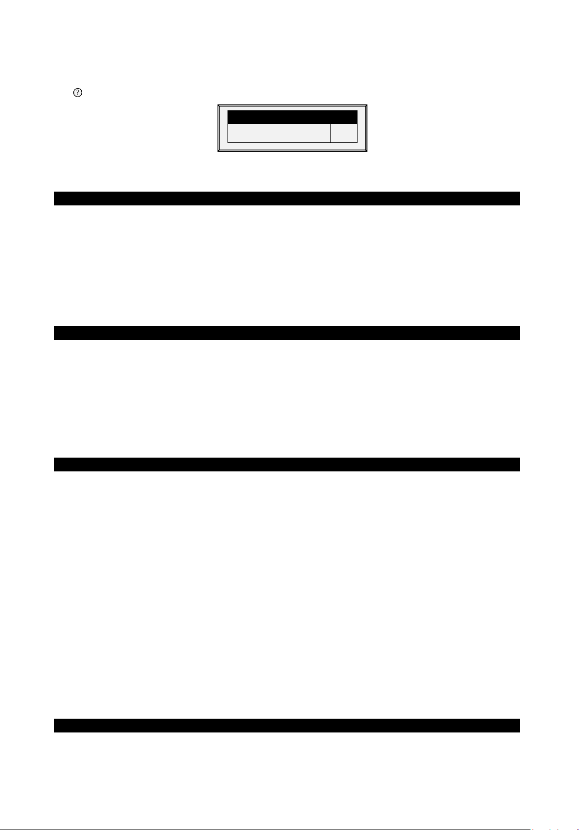
ALARM SETTING
Advanced Alarms
YES
5.5.1 A
•
•
•
•
•
•
LARM SETTING HELP | SET DEFINITIONS
While viewing the Alarm Setting menu:
Press
SYSTEM PARAMETERS
HELP
, select
SET
, and press
ENTER
Advanced Alarms: When selecting YES, the following additional alarms appear on the
ALARM SETTINGS screen (press MENU and then ENTER to reenter the screen).
Water on Demand Alarms
High/Low Pressure Diff (PSI): Sends an alarm when the difference between the current WOD
pressure and the defined pressure reaches these levels. 0 means that the alarm is disabled.
Shutdown Pressure Diff (PSI): Shuts down the Water on Demand system when the pressure
reaches this level.
o
Shutdown pressure must be equal to or higher than the High/Low Pressure Difference.
o
However, to disable this alarm set it to 0 (zero), even if the High/Low Pressure is
above 0.
Feed Alarms
Allow Feed Alarm From/To: Set a starting time from which the controller can send feed
shortage alarms.
Bin 1/2 Low Feed Alarm Limit: Alarm if feed in Bin 1/2 is below this limit and time is between
From and To limits.
Feed Alarm Limit (per hour): An alarm is generated if the feed flow is greater than this
amount. This alarm is activated when a problem arises inside the barn (as opposed to when
something happens to the feed scale).
Water Overflow Alarms
•
According to Light Table: Change overflow alarm level when the lights are off.
•
First Day: Overflow on the FIRST day applies to the first day operation. You can define a first
day at which to start increasing the overflow limit automatically. Days prior to the ‘First Day’ use
the First Day overflow limit; days following the first day have an incremental curve toward the
LAST DAY OVERFLOW parameter setting.
•
Overflow on First Day: Number of gallons/liters per minute that generate an overflow alarm
on the first day.
•
Last Day: Set the last day for the Overflow curve.
•
Overflow on Last Day: Overflow (Gallons/Liters) on the last day sets the maximum overflow
limit will be continued after that day.
•
Overflow At Dark: Select overflow limit. When it is dark, controller checks every minute.
•
Overflow Alarm Delay: Define delay time before the controller generates an overflow alarm.
•
Extra Delay At Light Start: When the first light appears, define the amount of minutes before
the controller begins to operate according to the set Overflow for that day.
•
Fogger Water Overflow: Define the water overflow for foggers (per minute).
Water Shortage Alarms
•
Allow Water Shortage Alarm From/To: Set the period for which the controller generates
water shortage alarms.
© Munters AB, 2021 54
Page 60

•
Shortage During Lights Off: Select whether water shortage alarm should be disabled when all
lights are out.
•
Quantity for Shortage: Minimum flow rate that must be maintained or a water shortage alarm
is generated.
•
Shortage Alarm Delay: Minimum period of time that the shortage must extend through before
generating an alarm.
•
Shortage Start Day: Define on what day shortage alarms begin. This parameter prevents false
alarms caused by young birds low water usage. Default: 0 (meaning alarms function normally
throughout the growth cycle).
Bird Scales Alarms
•
Allow Bird Scale Alarms From/To: Set time frame for which the controller begins and ends
generating alarms for the bird scale.
Auxiliary Alarms
•
Assign auxiliary alarms in the Install menu. Note that digital sensors, auxiliary alarm input with
related relay must always match their relay status.
•
Related Relay For Aux Alarm 1/2/3/4: Relay for Auxiliary Alarm 1/2/3/4.
•
AUX. Alarm Delay (sec): Separate from the Global Alarm Delay. If there is a dry contact, the
alarm is sent after the defined AUX. Alarm Delay.
Circuit Breaker Alarm
•
Temperature for Circuit Breaker Alarm: Set circuit breaker alarm temperature.
CO2 Sensor Alarm
•
CO2 High Level: Set the maximum allowed CO2 level above which an alarm is sent. The
alarm ceases when the CO2 drops below this level. If the user acknowledges the alarm, the
alarm messages temporarily cease (for the reminder time).
Humidity Sensor Alarm
•
Humidity Alarm Enabled: Mark this parameter as Yes to enable the Humidity High Level alarm
and the Humidity Sensor Fail alarm.
•
Humidity High Level Alarm: Set the maximum allowed humidity level above which an alarm is
sent. The alarm ceases when the humidity drops below this level. If the user acknowledges the
alarm, the alarm messages temporarily cease (for the reminder time).
Ammonia Alarm
•
Ammonia High Level: Set the ammonia level at which an alarm is sent.
Potentiometer Alarm
•
Enable potentiometer alarms, which send an alarm when potentiometer controlled devices fail.
To enable, sent the time frame. If the from/to times are set to 0:00 (default) the alarm is
disabled.
© Munters AB, 2021 55
Page 61

ALARM RESET
Alarm Reset
NO
ACTI VE ALARM
No.
Message
1
Switches Changed
NO
SIREN ONLY
Owner Password
Visitor Password
_ _ _ _
5.6 Alarm Reset
This menu functions as an alarm and siren reset.
•
Alarm Reset:
o
NO: Does not reset alarms
o
SIREN ONLY: Resets only the siren, alarms remain
o
YES: Resets alarms
Selecting YES:
o
Clears the alarm relay for all current alarms. The alarms may remain valid, but the unit
does not register new alarms. If a new alarm occurs, or an existing alarm clears and
reoccurs, the alarm relay signals again (after any appropriate delay).
o
Restores normal operation after an emergency pressure or feed overrun incident. If the
controller experiences a high-pressure alarm for too long, it enters emergency pressure
operation by opening all known air sources. Curtains open to preset amounts as set in
Control | Static Pressure. If you select SIREN ONLY, the alarm relay returns to the no
alarm condition, but the emergency pressure status continues.
o
Restores normal operation after a feed overrun situation that calls for turning off the
feeding system. If the feed monitor senses the cross auger runs too long, it trips a feed
overrun alarm and optionally turns off the feed system. If you select SIREN ONLY, the
alarm relay returns to the no alarm condition, but the feed overrun status continues.
5.7 Password
PAS SW ORD
User-1 Password
User-2 Password
User-3 Password
User-4 Password
User-5 Password
The owner can set new passwords for himself, all users and the Visitor. The owner cannot see user
passwords once entered or changed by the users. The users can access the controller and make changes
to all controller settings and their own password. A user can only see and change his own password. The
visitor can access the controller, but cannot make changes. Each time someone accesses the controller
with a password, an event is recorded in the History | Table of Events.
If your controller uses passwords, the controller also requires a password entry to acknowledge switch
position changes. If the switch change is not acknowledged the controller signals an alarm.
_ _ _ _
_ _ _ _
_ _ _ _
_ _ _ _
_ _ _ _
© Munters AB, 2021 56
Page 62

Scale Layout, page 57
SCALE
SCALE LAYOUT
Ch.
Type
GENERAL SETTINGS
6 Scale Menu
The following sections detail the weighing functions.
•
•
General Settings, page 57
•
Bird Scale Setting, page 58
•
Bird Curve/Bird Weight, page 59
•
History, page 61
•
Feed Conversion, page 63
•
Test, page 63
•
Calibration, page 63
1. SCALE LAYOUT
2. GENERAL SETTINGS
3. BIRD SCALE SETTING
4. BIRD CURVE
5. HISTORY
6. FEED CONVERSION
7. TEST
8. CALIBRATION
6.1 Scale Layout
Use Scale Layout to map the scales connected to the controller.
1
2
Scale 1
Scale 2
This screen does not require user input.
6.2 General Settings
This menu sets general weighing parameters.
NOTE This function does not appear in Version 6.19 and above.
Bird Scale Mode
Uniformity Range (5-30%)
Curve Selector (for mixed)
Weigh During Feed Days
SEXED
10
BROILER
NO
•
Bird Scale Mode: Select the weighing method:
o
SEXED: Considers all birds to be the same sex or ‘unisex’ as in mixed broilers. It
computes its own reference weight or acceptable range from the weighed birds.
© Munters AB, 2021 57
Page 63

Start Time:
Start Time:
End Time:
End Time:
Range – (0-100%):
Range – (0-100%):
Reference Weight 1:
Reference Weight 2:
BIRD SCALE SETTING - SEXED
Start Time
Reference Weight 2
18:00
0.11
Start Time
Lower (Below Reference %)
18:00
10
Factory Default Curve
N
o
o
MIXED: Considers the flock to be mixed males and females, with the goal of identifying
each bird weight as male or female, which is, classifying it according to a preprogrammed pair of expected weight curves.
•
Uniformity Range (5-30%): Controller classifies bird weights within this percentage of the
average as uniform. Default is 10%.
•
Curve Selector (for mixed): There are three standard pairs of pre-programmed weight curves.
If you use the mixed weighing method, edit the curves to match your expected growth profile
(BROILER, TURKEY, or BREEDER).
•
Weigh During Feed Days: Allow weight data to be recorded on feed days. When set to NO,
this data is discarded. Default: No
6.2.1 G
ENERAL SETTINGS HELP | SET DEFINITIONS
While viewing the General Settings menu: Press HELP, select SET, and press ENTER
•
Factory Default Curve: Select YES to return bird curves to the factory default settings
BIRD CURVE
6.3 Bird Scale Setting
Define at least one scale, silo, or feed scale in Scale Layout.
•
Bird Scale Setting, Version 9.18 and Below
•
Bird Scale Setting, Version 9.19
6.3.1 B
IRD SCALE SETTING, VERSION
There are two different weighing options available; select the option in
AND BELOW
9.18
BIRD SCALE SETTING - MIXED
Scale > General Settings
.
End Time
Upper Range (Above Reference %)
Lower Range (Below Reference %)
Reference Weight 1
•
the scale to begin weighing
•
scale to stop weighing
•
below reference weight
•
for Scale 1
•
© Munters AB, 2021 58
for Scale 2
19:00
30
2
0.13
Set the hour you would like
Set the hour you would like the
Band above and
Starting out weight
Starting out weight
End Time
Male Range
Upper (Above Reference %)
Lower (Below Reference %)
Female Range
Upper (Above Reference %)
•
Set the hour you would
19:00
20
10
20
like the scale to begin weighing
•
Set the hour you would
like the scale to stop weighing
•
Band above
and below reference weight
Page 64

Weighing Method
Auto
Upper Range [%]
25
Lower Range [%]
25
Auto
6.3.2 B
IRD SCALE SETTING, VERSION
•
Bird Scale Setting Screen
•
Bird Scale Setting | Set Definitions
9.19
6.3.2.1 Bird Scale Setting Screen
In this screen, select the algorithm used to calculate the bird curve that appears in Bird Weight, Version
9.19. There are three options:
BIRD SCALE SETTING
Custom
Cobb 500
Cobb 700
•
Auto: Set the first target weight. The controller then automatically calculates each days
reference weight.
•
Custom: The controller provides a weight vs growth day curve, which the user can edit as
required.
•
Factory Default Curve: The controller loads an industry standard bird curve. This curve cannot
be edited.
Ross 308
Ross 708
6.3.2.2 Bird Scale Setting | Set Definitions
While viewing the Bird Scale Setting menu: Press HELP, select SET, and press ENTER.
BIRD SCALE SETTING
•
The upper/lower range parameters defines the range of weights that are recorded. The weights
of birds that exceed differ from the bird curve by these amounts are discarded.
6.4 Bird Curve/Bird Weight
•
Bird Curve, Version 9.18 and Below
•
Bird Weight, Version 9.19
© Munters AB, 2021 59
Page 65

Day
Female
Male Weight
Weight
1
49
0.11
5.95
0.13
8.22
Now
1.87
2.44
Bird Curve Offset
0.2
Current Weight
1.00
6.4.1 B
IRD CURVE, VERSION
AND BELOW
9.18
This screen displays data according to growth day for broilers, turkeys, or breeders, previously set in
General Settings.
BIRD CURVE
7
14
21
28
35
42
0.31
0.66
1.26
2.07
3.15
4.45
0.35
0.70
1.54
2.73
4.27
6.15
Edit the growth days and weights for the bird curves to fit individual preference.
6.4.1.1 Bird Curve Help | Set Definitions
While viewing the Bird Curve menu: Press HELP, select SET and press ENTER.
BIRD CURVE
Bird Curve Offset: Enter the factor used to adjust the weight curve. This amount is added to the “Now”
field. Range: 0.0 – 10.0 Kg/Lb.
6.4.2 B
IRD WEIGHT, VERSION
9.19
This screen displays the expected bird weight according to growth day. Which screen is displayed is
dependent on the curve selected in Bird Scale Setting, Version 9.19 (page 59).
•
Bird Weight Screens
•
Bird Weight Help | Set Definitions
6.4.2.1 Bird Weight Screens
•
Auto Method
BIRD WEIGHT AUTO METHOD
o
If you selected Auto in Bird Scale Setting, the Bird Weight screen displays the target
weight for the current growth day. You can edit the weight as required.
•
Custom Weight
© Munters AB, 2021 60
Page 66

Day
Weight
0
0.00 1 0.00 2 0.00 3 0.00 4 0.00 5 0.00
Day
Weight
0
0.09 1 0.13 2 0.16 3 0.20 4 0.24 5 0.30
BIRD WEIGHT
Curve Offset
0.00
CUSTOM CURVE
o
If you selected Custom in Bird Scale Setting: Edit the weights as required.
•
Factory Default Curve
WEIGHT CURVE
o
If you selected a Cobb or Robb Curve in Bird Scale Setting, the Bird Weight screen
displays each day’s target weight using an industry standard. These data points are
read-only.
6.4.2.2 Bird Weight Help | Set Definitions
While viewing the Bird Weight menu: Press HELP, select SET and press ENTER.
NOTE Auto method does not feature a help screen.
• Curve Offset: Enter the factor used to adjust the curve. This amount is added to the “Now”
field. Range: -2.000 – 2.000 Kg / -4.40 - 4.41 Lb.
6.5 History
The scale history shows bird weight statistics. You can review daily data for each scale, or separately.
•
History, Version 9.18 and Below
•
History, Version 9.19
6.5.1 H
•
•
ISTORY, VERSION
In Version 9.17 and below, the unit records the data of up to two-bird scales; if you have more
than one scale-1, data is combined.
In Version 9.18, the controller records up to four scales.
AND BELOW
9.18
NOTE Only Broilers/Layers Mode supports this function
© Munters AB, 2021 61
Page 67

Day
Avg.
NO.
S.D.
Unif.
C.V
17
26
0.000
0.000
0
0
0.000
0.000
0
0
0
0
HISTORY
Day
Avg.
Scale1
Scale2
Scale3
Scale4
NO.
S.D.
Unif.
C.V
17
26
0.000
0.000
0.000
0.000
0.000
0.000
0.000
0.000
0.000
0.000
0
0
0.000
0.000
0
0
0
0
HISTORY
Day
Avg.
D.Gain
Unif.
No.
Scale1
D.Gain
Unif.
No.
1
0.00
0.00
0.00
0.00
0.00
0.00
0.00
Figure 4: Version 9.17 or below
18
19
20
21
22
23
24
25
0.000
0.000
0.000
0.000
0.000
0.000
0.159
0.000
0.000
0.000
0.000
0.000
0.000
0.000
0.000
0.000
18
19
20
21
22
23
24
25
0.000
0.000
0.000
0.000
0.000
0.000
0.159
0.000
0.000
0.000
0.000
0.000
0.000
0.000
0.000
0.000
HISTORY
0
0.000
0
0.000
0
0.000
0
0.000
0
0.000
0
0.000
1
0.000
0
0.000
0.000
0.000
0.000
0.000
0.000
0.000
0.000
0.000
0
0
0
0
0
0
100
0
0.000
0.000
0.000
0.000
0.000
0.000
0.000
0.000
0
0
0
0
0
0
0
0
0
0.000
0
0.000
0
0.000
0
0.000
0
0.000
0
0.000
1
0.000
0
0.000
0
0
0
0
0
0
100
0
0
0
0
0
0
0
0
0
Figure 5: Version 9.18
•
If you selected SEXED weighing, the history includes average data for the combined scales,
and on the next screens separate data for each scale.
•
If you select MIXED weighing, the history includes average data for all birds, and separate
male and female data for Scale 1 and for Scale 2.
o
Use the arrow keys to scroll to the separated scale data, or up and down for data that is
off screen.
o
The average and the number of weights are the usual definition. The Standard Deviation
is the usual biased estimator (see a suitable textbook on statistical measurements). The
Uniformity is the industry standard 10% uniformity (number of birds per 100 within 10%
of the average weight), and the Coefficient of Variation or C.V. is the normalized
standard deviation (standard deviation divided by average times 100 %.)
6.5.2 H
ISTORY, VERSION
2
0.00
3
0.00
0.00
0.00
9.19
0.00
0.00
0.00
0.00
0.00
0.00
0.00
0.00
0.00
0.00
•
The D. Gain shows difference between the current average weight and the previous day’s
average weight; the data comes from all the scales.
•
No daily gain is shown for individual scales.
© Munters AB, 2021 62
Page 68

FEED CONVERSION
Bird
Weight
Daily
Feed
Feed
Conversion
17
0.00
0
N/A
TEST
Type
Status
Scale-1
O.K.
Scale 2
O.K.
Scale 3
O.K.
Scale 4
O.K.
6.6 Feed Conversion
This screen displays the amount of feed converted into the bird’s weight.
Day
18
0.00
0
N/A
6.7 Test
This section is a real time table to show the statuses of all scales connected to the controller.
1. In
Scale > Scale Layout
2. In
Scale > Test
, test the scales as required.
(refer to page 57), select the required scale types.
- 1 - - 2 - - 3 - - 4 -
A/D
Weight
2024
0.222
2010
35.768
1891
0.000
1893
0.000
Make sure that all statuses are O.K. If any of them show a different status, the scale is not installed
properly. Unused positions can also show O.K.
6.8 Calibration
This menu calibrates the scales connected to the controller.
1. In
Scale > Scale Layout
2. In
Scale > Calibration
(refer to page 57), select the required scale types.
, calibrate the scales.
© Munters AB, 2021 63
Page 69

SCALE CALIBRATION
Channel Scale
—
—
Press ENTER to Calibrate or
Offset
CALIBRATION PROCESS
CALIBRATION PROCESS
CAUTION Do not use scales while calibrating.
3. Follow instructions on the bottom section of the screen.
4. Wait until the progress bar displayed shows 100%.
5. Place a known weight on the scale and enter its weight.
6. Wait until the calibration progress bar reaches 100%.
7. Ensure “Good Calibration.”
Weight Factor
Scale-1
Scale-2
RIGHT ARROW to change Factor or
—
—
CHANNEL 1
1008
1008
CHANNEL 1
100%
CHANNEL 1
25%
CALIBRATION PROCESS
CHANNEL 1
Place a Known Weight and enter
Weight 1.000
CALIBRATION PROCESS
GOOD CALIBRATION!
the
CHANNEL 1
© Munters AB, 2021 64
Page 70

HISTORY
7 History Menu
In the History Menu you can view data regarding:
•
Temperature
•
Humidity
•
CO2
•
Water
•
Feed
•
Mortality
•
Heaters
•
Radiant Heaters
•
Alarms
•
Table of Events
•
History View
1. TEMPERATURE
2. HUMIDITY
3. CO2
4. WATER
5. FEED
6. MORTALITY
7. HEATERS
8. RADIAN T HEATERS
9. AL ARMS
10. TABLE OF EVENTS
11. HISTORY VIEW
7.1 Temperature
The temperature history menu stores minimum, average and maximum temperatures by growth day. The
average is weighted, so if most of the day has been warm the average is closer to the maximum than the
minimum.
7.2 Humidity
The humidity history menu stores minimum, average and maximum inside humidity by growth day. The
average is weighted, so if most of the day has been humid the average is closer to the maximum than the
minimum.
7.3 CO2
The CO2 history menu stores minimum, average and maximum inside CO2 levels by growth day. The
average is weighed, therefore if most of the day has been high CO2 levels the average is closer to the
maximum than the minimum.
© Munters AB, 2021 65
Page 71

Day
Water P.bird
Water-1
Water-2
1
0.0 (%)
0.0 (%)
0.0 (%)
Feed P.Bird
Daily
Feed-1
Daily
Feed-2
Daily 1 0.0 (%)
0.0 (%)
0.0 (%)
7.4 Water
The water menu records daily water consumption and shows the daily differential change from the
previous day in percent. You must have the water monitor digital inputs connected. You can monitor up to
two drinking water meters, total drinking water, total water, cool pad, fogger and cold pad flush
consumption.
As an option, the user can monitor the water per bird.
1. Go to History > Water > Help.
2. Enable Display History Per Bird.
WATER
The screen displays the amount and the percentage change.
7.5 Feed
The feed menu records daily feed consumption and shows the daily differential change from the previous
day in percent for two feed bins/fill systems. You must have a feed bin weighing system installed for the
feed system, or monitor the auger system.
The feed data can be based on one of the following inputs. If more than one input is installed, priority is
according to the order of the bulleted list.
•
Feed Bin: If feed bins (load cells) are installed, feed consumption data of each bin is based on
the feed bin weight.
Feed Count: If a feed count sensor is installed feed consumption for each feed count input is
•
based on the feed count method settings (refer to Digital Sensors, page 82).
As an option, the user can monitor the feed per bird.
1. Go to History > Water > Help.
2. Enable Display History Per Bird.
WATER
Day
7.6 Mortality
The mortality history menu maintains daily summaries of mortality, cull and total dead. It also shows the
percentage dead and gives an updated count of bird inventory. The history is maintained separately for
male, female and total. Use the left and right arrow keys to switch to the next screen.
7.7 Heaters
The AC-2000 3G maintains daily total run times of each heater. The table fills several screens; to view the
off screen data, use the arrow keys to scroll. The data is in hours: minutes format.
© Munters AB, 2021 66
Page 72

7.8 Radiant Heaters
The AC-2000 3G maintains daily total run times of each radiant heater, including separate data for low
level and high-level heaters. The table fills several screens; to view the off screen data, use the arrow keys
to scroll. The data is in hours: minutes format.
7.9 Alarms
The alarm history records the growth day and time of each alarm. Alarms that are currently active show
up as flashing on the screen. Alarm history is not reset when using
New Flock
. The last 250 alarms are saved, and as the table is filled, new alarms push out the older
Management, Growth Date & Flock >
alarms.
7.10 Table of Events
The AC-2000 3G records significant events with growth day and time stamp. The Table of Events is 1000
events long and is not reset when using
push out the older events.
Management, Growth Date & Flock > New Flock
. New events
Typical events recorded are switch changes, entry into tunnel mode, minimum ventilation, alarm resets,
ventilation mode changes and more. The Table of Events is an excellent tool to determine whether your
controller is going in and out of tunnel due to marginal settings as well as finding and identifying
problems
Go to the Table 4, page 105 to view all the available events.
7.11 History View
The History View menu has detailed history on a variety of sensors and data.
1. Go to
2. Go to
collect data as frequently as by the minute or only on a daily basis. Factory default collects onehour data on a selection from the choices below.
•
In the HISTORY VIEW | HELP | SET menu, set the desired choice by using the '+/-'.
•
The options are as follows:
•
•
•
•
•
•
•
•
Help > Set
Install > Setup> History Resolution
under History View to select the particular data to collect.
to set the frequency of your data collection. You can
Under Help | Graph you can select a variety of graphs of the detailed history.
Target Temp.
House Temperature: Minimum, Average and Maximum
Temp – 1-6: Minimum, Average and Maximum
Attic Sensor: Minimum, Average and Maximum
Outside Temperature: Minimum, Average and Maximum
Humidity In/Out: Minimum, Average and Maximum
Water Consumption
Feed Consumption
Level of Ventilation
•
Altering choices erases old data and starts a fresh data set.
© Munters AB, 2021 67
Page 73
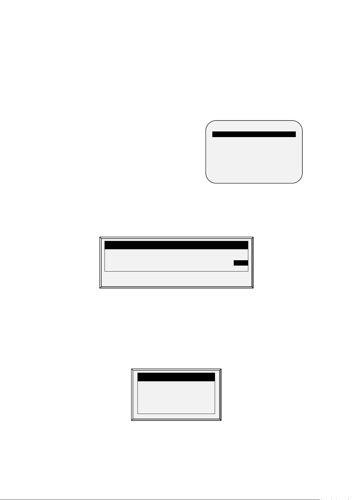
Relays, page 68
TEST
01
02
03
04
05
06
07
08
09
10
11
12
13
14
15
16
17
18
19
20
Press Enter to turn relay on/off.
ALARM TE ST
8 Test Menu
The Test Menu screen shows internal information in order to verify that the AC-2000 3G is operating
correctly. Moreover, it can help find broken wires or any other problems related to it.
•
•
Alarm, page 68
•
Analog Sensors, page 69
•
Digital Sensors, page 69
•
Analog Output, page 69
•
Static Pressure, page 70
•
Communication, page 70
1. RELAYS
2. AL ARM
3. ANALOG SENSORS
4. DIGITAL SENSORS
5. ANALOG OUTPUT
6. STATIC PRESSURE
7. COMMUNICATION
8.1 Relays
This menu displays a screen of identified relays installed in the controller. Use this option to determine
faulty hardware. If a relay is active, the relay number has a black background.
REL AYS
8.2 Alarm
Press Enter to toggle the Alarm Relay.
•
ON means alarms are functioning.
•
OFF means alarms are not functioning.
Note that the alarm relay is powered for the ‘NO ALARM’ condition to automatically provide Power Fail
Alarm in case of a power failure. That is, the Normally Open side is closed during NO ALARM.
© Munters AB, 2021 68
Relay Alarm: ON
Press ENTER For On/Off
Page 74

ANALOG IN TEST
In.
Sensor
A/Value
1
Temp. Sensor 1
470
64.0 2 Temp. Sensor 2
426
87.2 3 Temp. Sensor 3
470
85.6 4 Temp. Sensor 4
426
82.0 5 Temp. Sensor 5
470
87.0 6 7 8 9
10
In.
Sensor
State
Counter
1
Water Meter 1
1 0 2
Water Meter 2
0 0
8.3 Analog Sensors
Observe the converter readings for analog sensors with this menu.
Define the sensors in Installation > Analog Sensors.
The readings can vary from 0 to 1023.
The values displayed in the 'Value' column indicate that the analog sensor is either operating or not
connected according to the following:
•
The value is in the range 0-1023. If the number is 1023 (or very close to it) the sensor is not
connected.
•
If the unit displays a 3-digit number, usually beginning with the digit '4: sensor is operating.
8.4 Digital Sensors
Define the sensors in Installation > Digital Sensors.
DIGITAL IN TEST
Observe the state of the two digital sensors. A ‘1’ indication implies a shorted input, a ‘0’ an open input.
The digital sensors operate with dry contact inputs such as the Arad Water Meter, or micro-switches.
You can apply a short/open input to each channel; the response is then displayed.
8.5 Analog Output
This selection tests light dimmers, variable speed fans, and variable heaters.
© Munters AB, 2021 69
Define the sensors in Installation > Analog Output.
1. Scroll to the required output.
Page 75

Output.
Sensor
0 – 10v
1
Light Dimmer 1
0.0 2
Light Dimmer 2
0.0
A/D Counts
126
To perform this test you must
2. Enter the test voltage and verify that the device is operating.
ANAGLO OUT TEST
8.6 Static Pressure
Observe the converter readings for the static pressure sensor. The nominal ‘zero’ pressure reading is 130.
Remove the air hoses from the brass connectors on the left side outside of the controller to check this
reading.
STATIC PRESSURE
8.7 Communication
This menu facilitates testing on communication networks. A multiplexer in loop back mode is used to test
the communication. The AC-2000 3G follows its own communication to check for failed hardware.
Follow the instructions displayed on the screen.
short RX with TX on the nonpriority channel of the
multiplexer
PRESS ENTER TO CONFIRM
© Munters AB, 2021 70
Page 76

Temperature Calibration, page 71
SERVICE
TEMPERATURE CALIBRATION
Sensor
Temp°
Factor
1
78.2
1.6 2 86.4
0.9 3 83.0
-1.5 4 86.2
0.8 5 85.2
-1.6 6 84.2
0.0
9 Service Menu
The Service Menu items calibrate various AC-2000 3G functions.
•
•
Humidity Calibration72
•
CO2 Sensor Calibration72
•
Static Pressure Calibrationa pagina 73
•
Light Sensor Calibration74
•
Feed Calibration74
•
Water Calibration, page 75
•
Ventilation Potentiometer Calibration, page 75
•
Save Settings to SD Card, page 76
•
Read from SD Card, page 77
•
WOD Calibration, page 78
1. TEMP. CALIBRATION
2. HUMIDITY CALIBRATION
3. CO2 CALIBRATION
3. STATIC PRESSURE CAL.
4. LIGHT SENSOR CALIBRATION
5. FEED CALIBRATION
6. WATER CALIBRATI ON
7. POTENTIOMETER CALIBRATION
8. NIPPLE FLUSHING
9. FEEDERS & DRINKERS
10. SAVE SETTINGS
11. LOAD SETTINGS
12. W.O.D/ CALIBRATION
9.1 Temperature Calibration
The AC-2000 3G temperature sensors are typically accurate to approximately 0.5º F within the range of
temperatures for poultry production. Calibrate them in this menu by adding/subtracting a constant
correction factor to each sensor. Adjust the sensor of your choice with the left/right arrow keys.
Calibrating against infrared or in air temperature sensors generally results in less accuracy than the basic
sensors have without calibration.
CAUTION Only calibrate the sensors if you have reason to believe that they are producing
inaccurate results.
To calibrate the sensor:
1. Obtain an accurate reference sensors and a pail of water at the approximate temperature
desired.
2. Stir the reference sensor together with the AC-2000 3G sensor vigorously in the bucket of water.
Keep hands off the sensor itself, so that it responds accurately to the water temperature. Stirring is
necessary to preclude stratification within the bucket of water.
© Munters AB, 2021 71
Page 77

Sensor
Humidity°
Factor
In-1
58.9
2.3
In-2
58.9
2.3
Out
N/A
---
CO2 SENSOR CALIBRATION
Value
PPM at 4 mA/1 VDC
26
PPM at 20 mA/5 VDC
3000
Factor (PPM)
22
C02 (ppm):
482
3. Call out the accurate reading to a second person standing at the AC-2000 3G. Walkie-talkie
radios may be a good idea.
4. The individual at the controller should double-check that you are calibrating the correct sensor.
You might warm/cool the sensor temporarily to see which sensor changes temperature
appropriately.
5. Once you determine the correct temperature and allow approximately one minute for
stabilization in the water, adjust the sensor reading at the controller.
6. Offset the factor using the left/right arrow keys.
•
Refer to Temperature Curve, page 9.
9.2 Humidity Calibration
To calibrate the humidity level, obtain a suitable humidity test kit, and use the procedures described there.
They are commonly available via the Internet.
CAUTION Only calibrate the sensors if you have reason to believe that they are producing
inaccurate results.
HUMIDITY CALIBRATION
•
Adjust the AC-2000 3G reading as needed using the left/right arrow keys.
Refer to Humidity Treatment, page 17.
9.3 CO2 Sensor Calibration
To calibrate the CO2 level, obtain a suitable test kit and use the procedures described in the kit. Ensure
that the house is well ventilated.
CAUTION Only calibrate the sensors if you have reason to believe that they are producing
inaccurate results.
•
Ppm at 4 mA / 1 VDC: Parts per million for 4 mA or 1 VDC
•
Ppm at 20 mA / 5 VDC: Parts per million for 20 mA or 5 VDC
© Munters AB, 2021 72
Page 78

A/D Counts:
110
Disconnect air hoses from the AC-2000
3G to zero the pressure
Then Press ENTER to calibrate
A/D Counts:
110
GOOD CALIBRATION
Press MENU to exit
•
Factor (ppm): (-/+) ppm shift from the current reading
CO2 (ppm): Current CO2 readings
•
•
Adjust the AC-2000 3G reading as needed using the left/right arrow keys.
•
Refer to CO2 Treatment, page 19.
9.4 Static Pressure Calibration
The Static Pressure should be 0 when there is no ventilation and the house is closed. When the controller
A/D counts is 100, this means that there is zero (0) static pressure.
CAUTION: The Static Pressure sensor is factory calibrated. Only calibrate the sensor if you have
reason to believe that they are producing inaccurate results.
NOTE:
Run AC-2000 3G for a few hours so that the temperature in the box becomes stable and only
then calibrate.
CAUTION
DO NOT blow the air into the hose to see of the pressure changes! The sensor is sensitive
and blowing air can cause irreparable damage.
To calibrate the Static Pressure Sensor:
1. Disconnect the air hoses.
2. Go to
Service > Static Pressure Cal
.
3. If the A/D count is 100 +/- 30 (70 to 130), press Enter.
4. If the A/D count is less than 70 or greater than 130:
a. Check for blocked air hoses or wind interference.
b. Adjust the zero pressure reading to approximately 100 by turning the calibration screw.
c. When the A/D count is within the permitted range, press Enter.
STATIC PRESSURE CALIBRATION
STATIC PRESSURE CALIBRATION
The static pressure sensor is located inside the controller in the upper left hand corner to the left of the
power supply.
© Munters AB, 2021 73
Page 79

Refer to Static Pressure.
9.5 Light Sensor Calibration
Installing a light sensor enables turning off the lights when there is sufficient outside light.
To calibrate the light sensor:
1. Go to
2. Define one sensor as a light sensor.
3. Go to
4. Press Help, highlight Set, and press Enter.
5. Scroll down to Light Sensor Active and set to Yes.
6. Place the sensor in the required location.
7. Go to
8. When the outside light is bright enough, press Enter
Install > Analog Sensors
Device > Light
.
.
Service > Light Sensor Calibration
.
9.6 Feed Calibration
The AC-2000 3G can use feed bin scales or less expensive digital monitoring devices to keep track of
your feed. This menu calibrates the digital monitoring devices.
To calibrate the digital monitoring device:
1. Select the feed counting method. Your digital monitoring device may generate a dry contact
pulse for each quantity of feed, or it may simply indicate that the feed is running.
2. Enter the quantity of feed per pulse in case you use a dry contact pulse. Otherwise, enter the
amount of feed delivered per minute of auger operation.
3. Select one of the following:
o
Pulse: Weight per pulse
o
Time: Weight per minute
4. Enter quantity (weight per minute or per pulse).
© Munters AB, 2021 74
Page 80

FEED CALIBRATION
WATER CALIBRATION
Water Per
Pulse
Water Per
Pulse
Water Per
Pulse
Fogger
–
Water Per
2.203
Pot
Device
Close
Current
Open
1
Vent 1
152 0 1000 2 Vent 2
152 0 1000
Feed 1 2
Method
Factor
Method Pulse: Weight per Pulse
Method Time: Weight per Minute
TIME
2.203
TIME
2.203
9.7 Water Calibration
The AC-2000 3G supports (up to) four dry contact pulse output water meters. Enter the quantity of water
per pulse for your water meters.
Water 1 –
Water 2 –
Cool Pad –
Time
Time
2.203
9.8 Ventilation Potentiometer Calibration
Use this screen to calibrate the ventilation potentiometer control. Potentiometer calibration is required
before ventilation can be controlled via a potentiometer.
POTENTIOMETER CALIBRATION
Before calibrating the potentiometers:
o
Disable the static pressure unit in
o
Define at least one relay as vent/inlet/tunnel in
o
Define at least one analog sensor as a potentiometer in
Install > Setup
.
Install > Relay Outlet
Install > Analog Sensor
.
.
NOTE After potentiometer calibration, the times displayed in the Vent/Curtain Setup screen change.
© Munters AB, 2021 75
To calibrate the potentiometer:
1. Select a potentiometer number.
2. Press Enter.
The device relay closes and then opens. As this takes place, the numbers in the Close, Current, and
Open columns change. After a few minutes, the process completes and a "Good Calibration"
message appears.
Refer to Vent & Curtain Levels, page 36 for details.
Page 81

9.9 Save Settings to SD Card
This menu enables the user to save his program settings to a SD card and transport them to another
controller for quick programming.
NOTE Verify that the SD card is in the “Unlocked” position (see the following illustration). The card
must be in the Unlocked position to enable software upgrades.
An SD card must have 20K free space to save settings.
1. Insert SD Card into place as shown above.
2. Go to
3. In the screen that appears, press YES.
4. In the screen that appears, select the required settings and press Enter.
5. In the screen that appears, press YES.
Service > Save to SD Card
.
Settings are saved to the card.
CAUTION While saving, do not remove the card or interupt the process in any way!
© Munters AB, 2021 76
Page 82

The following tables can’t be uploaded.
Press MENU to Continue
LOAD SETTINGS REPORT
Do you want to proceed with the procedure?
9.10 Read from SD Card
This menu enables reading a saved program from a SD card into the controller quickly and reliably rather
than configuring the settings manually.
CAUTION Make sure that the program data is identical to the relay layout of the controller.
An SD card must have 20K free space to save settings.
1. Insert SD Card into place.
2. Go to
Service > Read From SD Card
.
3. In the screen that appears, select the required settings and press Enter.
4. In the screen that appears, press YES.
CAUTION While reading, do not remove the card or interupt the process in any way!
9.10.1 L
OAD SETTINGS REPORT
NOTE Version 9.19 and above supports this function.
When uploading settings to a controller, AC-2000 3G which tables (if any) will not be transferred.
Compatibility issues might arise in cases when transferring settings between controllers using different
software versions or having different configurations. By listing which tables will not transfer, the user
knows which tables must be defined manually.
1. Go to Service > Load Settings.
2. In the screen that appears, select YES and press Enter.
3. Select the required settings and press Enter.
4. If there are any incompatible tables, a list of the pathways appears.
LOAD SETTINGS REPORT
Install > Light Dimmers
Device > Light
Device > Light > Set
Scale > Scale Layout
5. Press Menu. The following message appears:
6. To proceed, select YES.
o
After loading the settings and resetting the controller, a record of incompatible tables can
be viewed in Table of Events (page 67). Note that pathway is shown using a number to
indicate the menu.
© Munters AB, 2021 77
YES NO
Page 83

TABLE OF EVENTS
Event
Day
Time
20
Tunnel Ventilation
2
1:15:50
21
Minimum Ventilation
2
1:30:43
22
8. Light Dimmers
2
4:14:44
23
2. Light
2
4:14:44
24
2. Light / Set
2
4:14:44
25
4. Scale Layout
2
4:14:44
26
Data Read From Plug
2
4:14:44
WATER ON DEMAND CALIBRATION
Volt
Pressure - PSI
WOD 1st Calib.
2.50
14.50
WOD 2nd Calib.
7.50
43.50
SYSTEM PARAMETERS
Pressure Reducer Factor
50.00
9.11 WOD Calibration
Define an analog sensor as WOD.
READ ME
Enter output voltage for first point.
Enter water meter measure pressure.
Repeat this for the second point.
1. In
Installation > Setup
o
Metric = Bar
o
Non Metric = PSI
2. In
Service > WOD Calibration
, set the Length Unit.
:
a. Enter the first voltage and check pressure data points.
b. Repeat for second data points.
3. Set the Help Definitions (optional)
9.11.1 WOD C
ALIBRATION HELP | SET DEFINITIONS
This parameter reduces the water pressure a user-defined factor.
WATER ON DEMAND
1. In
Install > Setup
2. In
Service > WOD Calibration
by 1/50 (bar or PSI). The factor is accurate to two decimal points.
© Munters AB, 2021 78
, define the Pressure unit.
> Help, define the reduction factor. Water pressure is reduced
Page 84

INSTALLATION
Ventilation Mode
PRECISION
Language
ENGLISH
Temperature Unit
F°
Pressure Unit
Wind Speed Unit
IN.W.C
METER/SEC
Fan Air Capacity Unit
CFM
Length Unit
NON METRIC
Weight Unit
LB
Growing Zones (1-4)
2
Minimum Vent
(Power)
Tunnel
YES
10 Install Menu
The Install Menu items are used when installing input and output devices, as well as configuring critical
parameters needed to run your controller properly.
Setup, page 79
•
Digital Sensors, page
•
82
Temperature
•
Definition, page 85
Communication, page 87
•
10.1 Setup
1. SETUP
2. RELAY L AYOUT
3. ANALOG SENSORS
4. DIGITAL SENSORS
5. ANALOG OUTPUT
6. INLET/CURT SETUP
7. TEMP DEFINITION
8. FAN AIR CAPACITY
9. HOUSE DIMENSIONS
10. COMMUNICATION
Relay Layout, page 80
•
Analog Output, page 83
•
Fan Air Capacity, page 86
•
Analog Sensors, page 81
•
Vent/Curtain Setup, page83
•
House Dimensions, page 86
•
SETUP
YES
Set the following:
Language
Temperature Unit
Pressure Unit
Wind Speed Unit
Fan Air Capacity Unit
Length Unit
Weight Unit
Growing Zones
Minimum Vent (Power)
Tunnel
History Resolution
As required
Celsius / Fahrenheit
Milibar / Inches of WC (Water Column) / Pascal / cm of WC / mm
of WC / None
Km Per Hour / Mile per Hour / Meter per Sec / Feet per Sec
Cubic feet per minute (CFM) / Cubic meter per hour (M3/H)
Meter / Feet
Pounds (LB) / Kilograms (KG)
1/2/3/4
YES (power) / NO
YES / NO
1 minute / 5 minute / 10 minute / 15 minute / 30 minute / 1 hour /
2 hours
© Munters AB, 2021 79
Page 85

Number
Output Function
REL AY LAYOUT
Relay
Function
Num
1
< None>
1. Heat
2
< None>
2. Radiant Low
3
< None>
3. Radiant High
4
< None>
4. Radiant Ignition
5
< None>
5. Tunnel Fan
6
< None>
6. Exhaust Fan
7
< None>
7. Stir Fan
8
< None>
8. Cooling
9
< None>
9. Cooling Pad
10
< None>
10. Fogger
N.O. Relay
REL AY LAYOUT
Relay
Function
Num
NO/NC
1
Vent Open
1 2
Vent Open
2 3
Vent Close
1 4
Vent Close
2 — 5
Heat 1 — 6 Heat 2 — 7 < None>
0 — 8
< None>
0 — 9
< None>
0 — 10
< None>
0 — N.O. Relay
10.1.1 S
TATIC PRESSURE UNIT DEFINITION
Enabling/disabling a static pressure unit determines the ventilation method used in the chicken/animal
house:
•
Static pressure unit enabled: After selecting any method, refer to Static Pressure, page 27 to
define the static pressure parameters.
•
No unit enabled: If you choose None, ventilation is controlled by time or a potentiometer.
Refer to Vent & Curtain Levels, page 36.
10.2 Relay Layout
Use this menu to define the devices connected to the controller. There are (up to) 20 available relays.
1. Select the requested choice from the menu list by using the up/down cursor keys (refer to
Supported Relays). AC-2000 3G numbers the relay automatically.
NOTE If required, you can set the relay number manually.
2. If required, press +/- to designate the relay as NO/NC.
3. To duplicate relays (meaning all definitions of a relay) use the 'As Relay # X' where 'X' stands for
a relay number defined already in the system. Scroll down to 37 to use this function.
10.2.1 S
UPPORTED RELAYS
1. Heaters
2. Radiant Heaters (Low/High/Ignite)
3. Tunnel Fan
4. Exhaust Fan
5. Stir Fan
6. Cool
7. Cool Pad
8. Fogger
9. Vent Open
10. Vent Close
© Munters AB, 2021 80
Page 86

Number
Output Function
REL AY LAYOUT
Relay Operation Mode
AC
NOTE: AC Relay Mode Recommended.
11. Vent Open
12. Vent Close
13. Curtain Open
14 Curtain Close
15. Attic Open
16. Attic Close
17. Vent Speed
18. Water
19. Feeder
20. Auger
21. Extra System
22. Alarm (N.C.)
23. Water Main
24. Water Bypass
25. Water Line
26. WOD
27. As Relay
28. AS Analog Output
10.2.2 R
ELAY LAYOUT – HELP | SET DEFINITIONS
While viewing the Relay Layout menu: Press HELP, select SET, and press ENTER.
•
Define relay operation mode: DC or AC.
AC mode produces less heat in the controller box.
10.3 Analog Sensors
This selection enables the user to configure the analog sensors. The AC-2000 3G regards various sensors
as well as circuit breakers as analog sensors. These sensors measure a continuous range rather than just
on or off.
© Munters AB, 2021 81
Page 87

ANALOG SENSORS
In
Function
Num
1
< None >
2 < None >
1. Temp Sensor
3
< None >
2. Hum. Sensor In
4
< None >
3. Hum. Sensor Out
5
< None >
4. CO2 Sensor
6
< None >
5. Light Sensor
7
< None >
8
< None >
9
< None >
CARD 1: Channel 1
ANALOG SENSORS
In
Function
Num 1 Temp Sensor
1 2 Temp Sensor
2 3 Temp Sensor
3 4 Temp Sensor
4 5 Temp Sensor
5 6 Temp Sensor
6 7 CO2 Sensor
1 8 Hum Sensor In
1 9 Hum Sensor Out
2
CARD 1: Channel 1 DIGITAL SENSORS
In
Function
1 < No < None >
2
< No 1 Water Meter
2
Cool Pad Water Meter
3
Fogger Water Meter
4
Feed Count
5
Auger Overtime
6
AUX . Ala rm
7
Low Water Pressure
CARD 1: Channel 1
DIGITAL SENSORS
In
Function
Num 1 Water Meter
1 2 Auger Overtime
1
CARD 1: Channel 1
•
Enter temperature / humidity sensors wired to each input (setup according to technician).
o
When installing a dedicated humidity sensor, set analog input 9 as the humidity sensor.
o
When installing temperature sensors, define inputs 1 - 6 only as temperature sensors.
o
When installing CO2 or lights sensors on inputs 1 – 6, place the jumpers on the 4 – 20
mA position (refer to Figure 14).
o
To install additional humidity sensors or potentiometers place the jumpers on:
0-3V position (humidity sensor)
POT position (potentiometers)
Refer to Figure 14.
•
If sensor numbers duplicate, the sensors average.
10.4 Digital Sensors
This option enables configuring two digital sensors. These sensors monitor both water and feed
consumption if the building is equipped accordingly. Digital inputs include on/off and pulsing inputs such
as auxiliary alarms, pulsing water meters and feed.
•
Enter sensors wired to each input (setup according to technician)
© Munters AB, 2021 82
Page 88

ANALOG OUTPUT
Out
Num
Min
V.Out
Max
V. Out
1
< None >
0
0.0
0.0 2 < None >
0
< None >
1. Variable Speed
2. Light Dimmer
3. Var. Stir Fan
4. Var. Heater
Card 1: Channel 1
ANALOG OUTPUT
Max
Out 1 Variable Speed
1
0.0
10.0 2 Light Dimmer
1
0.0
10.0
Card 1: Channel 1
VENT / CURTAIN SETUP
Open
(sec)
Close
(sec)
~
Curtain 1
NONE
60
60 Curtain 2
NONE
60
60 ~ Inlet 1
NONE
60
60
10.5 Analog Output
This selection controls light dimmers, variable speed fans and variable heaters. Select the required output
function from the menu list and insert the approximate output voltages.
Function Num
Out
Function Num
Num
Min
V.Out
•
Enter sensors wired to each input (setup according to technician). The above is an example of
an analog output configuration
•
To configure the light dimmers, refer to Light, page 43.
•
To configure the variable speed fans, refer to Stir Fan Levels, page 37.
•
To configure the variable heaters, refer to Temperature Curve Help | Set Definitions, page 10.
10.6 Vent/Curtain Setup
Use this screen to define the ventilation opening and closing mechanism. You can use one of these two
methods:
•
Time
•
Potentiometer
V.
If you map a curtain or vent to a potentiometer, the AC-2000 3G controller uses that method (and not
time).
Define at least one relay as curtain, tunnel, or vent.
NOTE After defining the method used, define the opening levels in Vent & Curtain Levels, page 36.
10.6.1 U
SING TIME TO CALIBRATE
Enter the number of seconds to open and close from limit to limit for each of the Vents and Curtains in
your installation. The AC-2000 3G then calculates the percentage of open and closed time and adjusts
the static pressure methods accordingly.
Curtain Pot
Set full open/full close time (in seconds) for Curtains, Tunnel, 1st & 2nd Vent, and Attic Vent.
NOTE Default is set at 60 seconds.
NOTE Munters recommends setting the Help parameters to maintain an accurate position.
NOTE The ~ symbol designates an analog output device.
© Munters AB, 2021 83
Page 89

Open
(sec)
Close
(sec)
~
Curtain 1
POT 1
60
60 Curtain 2
POT 2
60
60 ~ Inlet 1
POT3
60
60
From Time
0:00
To Time
0:00
Number of Steps
0
Power Vents Calibration
NO
Proximity to Edge %
10
Close Below This Temp. (out)
0.0
10.6.2 U
SING A POTENTIOMETER TO CALIBRATE
Each curtain/vent/inlet can be mapped to a potentiometer. Potentiometer feedback enables
precise positioning on each specific device opening value. In this screen, assign a potentiometer to
a device.
VENT / CURTAIN SETUP
Curtain Pot
1. Map the analog sensors as potentiometers as required (Analog Sensors, page 81)
2. Map the curtain/vent/tunnel to a potentiometer in this screen.
NOTE The number of the devices that you can map equals the number of potentiometer relays.
3. Calibrate the potentiometer (Ventilation Potentiometer Calibration, page 75).
NOTE After calibrating the potentiometer, the times shown here change to reflect the calibration
process.
In the event that the potentiometer fails (meaning there is no value change during the curtains/vents/inlets
movement):
•
Alarm message is transmitted
The specific curtain/vent/inlet mapped to the failed potentiometer starts operating by time
•
calculation, using the times calculated by the calibration process. However, if required you can
enter new opening and closing times.
10.6.3 V
ENT/CURTAIN HELP | SET DEFINITIONS
These parameters enable maintaining an accurate curtain position when using time to calibrate.
While viewing the Vent/Curtain menu: Press HELP, select SET, and press ENTER.
SYSTEM PARAMETERS
CURTAIN CALIBRATION
•
From/To Time: Time period in which calibration is enabled
•
Number of Steps: number of steps for automatic calibration: Set calibration point for curtain
after desired amount of curtain opening/closing (steps). During calibration, if the curtain is
open more than 50% it opens to 100%, calibrates, and returns to the previous position. If the
curtain is open less than 50% it closes to 0%, calibrates, and returns to the previous position.
Default: 99.
•
Power Vents Calibration: This parameter enables automatic calibration of air inlets when
recovering from a power outage. In many installations the backup system, such as Munters'
FBU-27, may have opened the air sources. When the AC-2000 3G takes over control again,
© Munters AB, 2021 84
Page 90

TEMPERATURE DEFINITION
Function
Temp. Sensor
1 2 3 4 5 6 7 8 9
Full House
√√√▪ ▪ ▪ ▪ ▪
Tunnel
setting
Atti c
▪ ▪ ▪ √ ▪ ▪ ▪
Outside
▪ ▪ ▪ ▪ √ ▪ ▪
Stir Fan 1
▪ ▪ ▪ ▪ √ ▪ ▪
~
Stir Fan 2
▪ ▪ ▪ ▪ √ ▪ ▪
~
Var. Heat 1
▪ ▪ ▪ ▪ √ ▪ ▪
the air inlets are incorrectly positioned. The calibration at power up feature synchronizes the
actual position and the controller.
•
Proximity to Edge %: Curtain will open or close based on this proximity to the edge. For
example, when set to 10%, the curtain closes when the opening is less than 10% and opens
completely when the opening is greater than 90%.
•
Close Below This Temp. (out): Curtains close when the outside temperature reaches this point.
This parameter requires defining a temperature sensor as an outside sensor (refer to
Temperature Definition, page 85).
NOTE The Proximity to Edge % parameter takes priority over the Close Below This Temp parameter.
Meaning, if the outside temperature mandates closing the curtain, the curtains will still open if
they are within the proximity defined in the Proximity to Edge parameter.
10.7 Temperature Definition
This menu assigns specific temperature sensors for various brood setups and for heater zones. Moreover,
assigning sensors to particular devices is possible. Note that if the sensors selection remains blank, the
default value is assigned.
Choose up to six temperature sensors for each item listed by using the '+/-' keys. The house, brooding
and tunnel sensors cause the current average to apply to devices when no specific sensor is assigned to
them. The current average substitutes for either failed or missing sensors.
▪ ▪ ▪ ▪ ▪ ▪ ▪
•
Press +/- key to add/remove to assign temperature sensors to corresponding function.
•
When an attic sensor is not installed, the attic vent is disabled.
Assign Temperature Sensors as required in Install | Temp Definition. Devices that do not
•
accept temperature sensors, such as Exhaust Fans, Tunnel Fans, Feed and Light do not appear.
NOTE When an attic sensor is not installed, the attic vent is disabled.
NOTE The ~ symbol designates an analog output device.
Note that Exhaust Fans and Tunnel Fans do not appear because the Ventilation Levels defined in Device
| Levels of Ventilation control their operation. Stir Fans appear even though the Device | Stir Fan
Levels apply to them because they simultaneously operate according Device | Stir Fan Programs where
specific sensor assignments are required in Program B and recommended in Program C.
© Munters AB, 2021 85
Page 91

Fan
CFM
Tunnel Fan 1
24600
~
Exhaust Fan 1
24600
10.8 Fan Air Capacity
This option enables defining the fans’ air capacity. Insert fan air capacity for both the exhaust and tunnel
fans. The units are as chosen in INSTALL | SETUP.
FAN AIR C AP ACITY
1. IN
Installation > Relay Layout
2. In
Installation > Setup
3. In
Installation > Fan Air Capacity
, define the fan air capacity unit.
and/or
Installation > Analog Output
, define the fans.
, define air capacity (default setting shown above).
NOTE This information enables the display of air capacity for each level in the Levels of Ventilation
table.
NOTE The ~ symbol designates an analog output device.
10.9 House Dimensions
The selection allows the user to set its' house dimensions. Set it according to actual house size. These
dimensions are used for calculating the wind chill factor (the chilling effect of the wind that can
significantly lower the temperature). This information enables the calculation of the Wind Chill factor
displayed in Hot Screen Key = 2 (Tunnel mode only).
•
Define height, width, and length of house (Controller calculates total area).
•
To set the dimensions in metric or non-metric units, go to
Installation > Setup
and scroll down to
Length Unit.
© Munters AB, 2021 86
Page 92

COMMUNICATION SETUP
Baud Rate
9600
House Number
1 1200
2400
9600
19200
38400
10.10 Communication
This menu defines the communication parameters.
•
Baud rate: This parameter is a measure of the communication speed for local or remote
communications to a PC. The default is 9600 represents a data rate of approximately 1000
characters per second. If the connection fails at this speed, try a lower speed.
•
House number: Each controller on a network must have a unique number so Munters’
communication software can distinguish individual controllers. Note that these numbers are
from 1 to 64.
© Munters AB, 2021 87
Page 93

Input Power Voltage
Relay Loads
Analog Inputs
Analog Output
Digital Inputs
Operating Temperature Range
Enclosure
Fuses
Professional certification
11 Technical Specifications
One Phase 115 ± 10 VAC (USA and Canada)
230 ± 20 VAC (Outside USA and Canada)
0.5 Amp, 50-60Hz
5.0 Amps, 250 Volts, Fused
0 - 11 Volts, 10 Milliamps Maximum
0 - 10 Volts
Current Limited with 100-Ohm Resistor
5 ma @ 5 Volts, Dry Contact
0° to +50° C (32° to 125° F)
Water and Dust Tight
Main fuse: 0.315 Amps, 250 Volts
Others: 5 Amps, 250 Volts
CAUTION For indoor use only!
© Munters AB, 2021 88
Page 94

12 Installation
This manual details the AC-2000 3G's physical installation procedures.
•
Precautions, page 89
•
Mounting the Unit, page 90
•
AC-2000 3G Wiring, page 91
12.1 Precautions
•
Grounding
•
Filtering
•
Checking the Battery Level
•
Frequency Inverters
12.1.1 G
ROUNDING
•
Always connect temperature and sensor shields to earth ground. Avoid mixing high voltage
wiring with sensor and low voltage wiring.
•
Keep the controller as far as possible from heavy contactor boxes and other sources of
electrical interference.
•
Do not connect communication wire shields, which go from one house to another at both ends.
Connect them at one end only. Connection at both ends can cause ground loop currents to
flow, which reduce reliability.
•
The COM connection for communications is not the shield wire. The COM, RX and TX wires
must connect to each other at all controllers.
12.1.2 F
ILTERING
If this installation includes a power inverter to drive variable speed fans, install an EMI filter in front of the
inverter, according to the specifications provided by the inverter manufacturer. Refer to the inverter
documentation.
12.1.3 C
HECKING THE BATTERY LEVEL
Check the battery once a year. The output must be 2.7 volts (minimum). Authorized personnel only must
replace the battery if the output is below the minimum required level or every five years.
12.1.4 F
REQUENCY INVERTERS
Frequency inverters can cause severe electrical and electromagnetic interference. Therefore, when
employing a frequency inverter, it is critical that you carefully follow the manufacturer's installation
instructions. In particular verify:
•
that the cable shielding between the inverter and any motor meets industry standards
•
proper grounding of the inverter's chassis and motor power cable
•
proper grounding of low voltage cable shield wire
•
that the controller and inverter cables are kept in separate conduits or wire bundles
© Munters AB, 2021 89
Page 95
•
1. Controller
•
2. Inverter
•
3. Place the controller at least five meters from the inverter.
12.2 Mounting the Unit
1. Install the AC-2000 3G in a dry well lighted area, preferably in an annex to the main poultry
house.
2. Mount it using the three holes provided; one in each of the left and right lower corners,
accessible from the front under the terminal strip cover, and one top center in the back. The top
center hole is a keyhole variety.
3. Install the screw for this hole first to about 0.1 inches of the wall surface. Then hang the control
on this screw. Install the other two screws to fasten the AC-2000 3G.
•
Always connect temperature and sensor shields to earth ground. However, do not connect
communication wire shields, which go from one house to another at both ends. Connect them
at one end only. Connection at both ends can cause ground loop currents to flow, which
reduce reliability.
•
The COM connection for communications is not the shield wire. The COM, RX and TX wires
must connect to each other at all AC-2000 controls.
•
Avoid mixing high voltage wiring with sensor and low voltage wiring.
•
Keep the AC-2000 as far as possible from heavy contactor boxes and other sources of
electrical interference.
Refer to Appendix D: Electrical Grounding for Controllers, page 113, for information on grounding the
unit.
© Munters AB, 2021 90
Page 96

1: Jumpers
2: Ground strip
3: Low power terminals
4: 20 Relays
5: 5 Amp fuses
6: Input power
7: Power supply
8: Static pressure sensor
9: 5V/RS-485 Termination
10: Communication card
12.3 AC-2000 3G Wiring
The following sections detail the AC-2000 3G wiring.
•
Board Layout, page 91
•
Relays, page 92
•
High Voltage Wiring (Relays), page 93
•
Terminal, page 94
•
Terminals Wiring, page 95
12.3.1 B
OARD LAYOUT
Figure 6: Board Components
© Munters AB, 2021 91
Page 97

12.3.2 R
ELAYS
Figure 7: Relay Functions
1. Relays 1 to 19: Each pair of terminals goes to one relay. These relays are fused with a
5-ampere, 250-volt slow blow fuses. The relays are normally open when not powered.
2. Relay 20: Three terminal blocks: This relay normally serves as an alarm relay. It is also fused
with a 5 ampere, 250 volt slow blow fuse, and can serve as an ordinary relay:
o
NC: Normally closed contact
o
Com: Common contact
o
NO: Normally open contact
3. Power: Three terminal blocks:
o
Neutral (N): Connect to the Neutral Power line.
o
Phase (~): Connect to the Phase Power line.
o
Ground (GND): Connect to a solid earth safety ground, normally with the bare safety
ground wire, or a green wire.
4. Ground: Connect the ground wire to the electrical system.
© Munters AB, 2021 92
Page 98

12.3.3 H
IGH VOLTAGE WIRING (RELAYS
)
1: Contactor
2: Cooler 1
3: Heater 1
4: Fan 1
5: Unprotected input
6: Protected output
7: Alarm system
activation occurs
when there is a
circuit opening
between NO and
COM.
8: Alarm system
9: 12 volt battery
Figure 8: High Voltage Wiring Example
NOTE The device connections (fan, heat, cool, etc.) shown in Figure 8 are only examples!
CAUTION Connect the AC-2000 3G power input to the protected output only!
© Munters AB, 2021 93
Page 99

12.3.4 T
ERMINAL SETUP
Figure 9: Terminal Functions
1. Up to two optional bird scales: Connect two wires of Scale 1 to SCALE 1 terminals (31,
32) and two wires of Scale 2 to Scale 2 terminals (15, 16).
2. Six temperature sensors (1, 2, 3, 17, 18, 19): The temperature sensor is a two wired
black shielded cable thermistor (RTS-2). Connect one wire to the temperature sensor
terminal and the other to common (4, 5, 20, 21) *Polarity does not matter.
3. Digital Inputs:
o
Digital 1 (29): Various functions
o
Digital 2 (13): Various functions
o
COM (30, 14)
4. Analog Outputs:
o
Analog 1 (28): 0 to 10V
o
Analog 2 (12): 0 to 10V
o
COM (27, 11): Connect the common wire of Analog Output 1 and 2 to these terminals.
5. Analog Inputs:
o
Humidity Sensor (24, 25, 26): Connect according to wire colors (white, red, black).
o
Analog 1 (8): Various functions.
o
Analog 2 (9): Various functions
o
Vpot (10), connected to obtain inlet feedback potentiometer voltage.
To setup the terminals:
1. Wire the terminals to the required device.
2. Place the jumpers in the corresponding position (Figure 14).
© Munters AB, 2021 94
Page 100

12.3.4.1 Terminals Wiring
Figure 10: Terminal Wiring: Temperature and Humidy Sensors
CAUTION Connect each cable’s shielding wire to the grounding strip. Figure 10 is an example only.
1: RTS 2: RHS + humidity sensor
3: Green wire 4: Black wire
5: White wire
NOTE Users wanting to install a second humidity sensor or CO2 sensor, refer to Appendix B: Installing
a CO2 Sensor and Second Humidity Sensor, page 107.
© Munters AB, 2021 95
 Loading...