

Munster Simms Engineering Ltd. Whale Expanse WW0801U, Whale Expanse IW0801U, Whale Expanse DW0801U Installation And User Instructions Manual
INSTALLATION AND
USER INSTRUCTIONS
Whale® Expanse™
Gas & Electric
Water Heater
More Heat, More Space, More Control*
Thank you for purchasing this Whale® product. For over 60 years Whale has led the way in the design and manufacturer
of water and waste systems including:-plumbing, faucets, showers, pumps and heating for mobile applications. Today’s
range features space and water heaters for caravans and motorhomes. The company and its products have built a
reputation for quality, reliability and innovation backed up by excellent customer service.
For information on our full product range visit: www.whalepumps.com
* More Heat, More Space, More Control compared to previous Whale Heating System Models
Model Number
Suffix
Description
Underfloor Installation Models
WW0801U
B or R or C
Underfloor Gas and Electric Water Heater (Install with Whale® Water Heater Control Panel)
IW0801U
B or R or C
Underfloor Gas and Electric Water Heater (Install with Whale iVan® Control Panel)
DW0801U
R
Underfloor Gas and Electric Water Heater (Install with Whale® Duo Control Panel)
Onboard Installation Models
WW0801O
B or R or C
Onboard Gas and Electric Water Heater (Install with Whale® Water Heater Control Panel
IW0801O B or R or C
Onboard Gas and Electric Water Heater (Install with Whale iVan® Control Panel)
DW0801O R
Onboard Gas and Electric Water Heater (Install with Whale Duo Control Panel)
Suffix Description
B Bulk Packaging
R Returnable Packaging
C Commercial Packaging
All work must be carried out by a competent person as defined by
BS7671 PART2.
All Whale gas products must be installed by a Qualified Gas Engineer in
accordance with the installation instructions and BS EN 1949-2011.
Please note if incorrectly installed a risk of electrocution exists.

CONTENTS
1. Principles of Operation
2. Specification
3. Application
4. Warnings
5. Parts List
6. Instructions for Installation
7. Instructions for Use
8. Maintenance
9. Trouble Shooting
10. Winterising and Draining
11. Service Support Details
12. EU Declaration of Conformity
13. Patents and Trademarks
14. Warranty
LIST OF IMAGES
Fig. 1 Components Drawing
Fig. 2 Dimensions – Underfloor Models Front View
Fig. 3 Dimensions – Underfloor Models Plan View
Fig. 4 Dimensions – Underfloor Models Side View
Fig. 5 Dimensions – Onboard Models Front View
Fig. 6 Dimensions – Onboard Models Plan View
Fig. 7 Dimensions – Onboard Models Side View
Fig. 8 Installation Locating Diagram - Underfloor Installation
Fig. 9 Cut Out Hole in Floor - Underfloor Installation
Fig. 10 Fit Mounting Bolts - Underfloor Installation
Fig. 11 Fit Water Heater - Underfloor Installation
Fig. 12 Secure Mounting Bolts - Underfloor Installation
Fig. 13 Attach Exhaust Flue - Underfloor Installation
Fig. 14 Attach Combustion Air Flue - Underfloor Installation
Fig. 15A Attach Flue to Flue Terminal - Step One
Fig. 15B Attach Flue to Flue Terminal - Step Two
Fig. 15C Attach Flue to Flue Terminal - Step Three
Fig. 16 Attaching Flue Terminal to the Vehicle - Underfloor Installation
Fig. 17 Flue Direction - Underfloor Installation
Fig. 18 Attaching Flue Brackets - Underfloor Installation
Fig. 19 Installation Locating Diagram - Onboard Installation
Fig. 20 Cut Out Hole in Floor - Onboard Installation
Fig. 21 Attach Exhaust Flue - Onboard Installation
Fig. 22 Attach Combustion Air Flue - Onboard Installation
Fig. 23A Attach Flue to Flue Terminal - Step One
Fig. 23B Attach Flue to Flue Terminal - Step Two
Fig. 23C Attach Flue to Flue Terminal - Step Three
Fig. 24 Attaching Flue Terminal to the Vehicle - Onboard Installation
Fig. 25 Flue Direction - Onboard Installation
Fig. 26 Attaching Flue Brackets - Onboard Installation
Fig. 27 Position Water Heater on the Floor - Onboard Installation
Fig. 28 Secure Water Heater to the Floor - Onboard Installation
Fig. 29 Connect to the Gas Supply
Fig. 30 Mains Electrical Connection
Fig. 31 Connect Cold Water Supply
Fig. 32 Connect Hot Water Supply
Fig. 33 Completed Installation - Underfloor Models
Fig. 34 Completed Installation - Onboard Models
Fig. 35 Whale® Water Heater Control Panel
Fig. 36 Whale Duo Control Panel
Fig. 37 Whale iVan® Control Panel
Fig. 38 Drain Valve Operation
2

The Whale® Expanse™ Water Heater is a gas and electric storage Water Heater. Expanse™ can be installed
internally, inside the vehicle or externally, under the vehicle. The unique design has an 8 litre capacity hot water tank
which incorporates versatile controls to deliver low current draw or fast heat up settings. With robust insulation and
no removable flue cover, the Whale® Expanse™ Water Heater only requires minimal maintenance.
Read the following carefully before installation
Model: WW0801U or IW0801U or DW0801U / WW0801O or IW0801O or DW0801O
WW0801U (Suffix: B or R or C) or IW0801U (Suffix: B or R or C) or DW0801U (Suffix: R)
Maximum dimensions inside vehicle:
Height: 180mm (underfloor), Width: 262mm, Length: 522mm, Dry Weight: 4.5kg
WW0801O (Suffix: B or R or C) or IW0801O (Suffix: B or R or C) or DW0801O (Suffix: R)
Maximum dimensions inside vehicle:
Height: 252mm, Width: 280mm, Length: 522mm, Dry Weight: 4.5kg
Nominal Water Capacity 8 litre
Gas: Butane/Propane 30mbar - CAT I
3B/P (30)
Classification of Storage Water Heater: Type: C
13
Nominal Heat Input: Gas 1.35kW
Standby Consumption: Gas 43W
Nominal Heat Input Electric 1.5kW
Electric: 230V a.c. 50 Hz 750/1500W
Maximum Current a.c: 6.5 amps
Nominal Voltage: 12V d.c. (10.1 Volt d.c. min. to 14.9 Volt d.c. max.)
Maximum Current d.c: 0.48 Amps (0.03 Amps on standby)
Maximum Water Supply Pressure: 190kPa (1.9 Bar)
Rated Pressure: 300kPa (3.0 Bar)
Pressure Relief Valve Setting: 300kPa (3.0 Bar)
Maximum Caravan Floor Thickness: 47mm
Ingress Protection Rating: IP45
Note: If connecting to mains water supply, a suitable water pressure regulator must be
connected to ensure that the
maximum supply water pressure does not exceed 190kPa (1.9 Bar).
Dry Storage Temperature: -20°C to 70°C
Maximum Water Temperature: Approx. 72°C
Typical heating up times from 15°C to 70°C:
Gas and 1.5kW Electric approx. 15 minutes. 1.5kW Electric (two electric elements only) approx. 24 minutes.
Gas only approx. 26 minutes.
For use only in road vehicles i.e. caravans and motorhomes only. Not suitable for caravan holiday homes i.e. mobile
homes or static caravans.
The Water Heater position must allow access for servicing and to the reset button.
Whale’s policy is one of continuous improvement and we reserve the right to change specifications without prior
notice.
2. SPECIFICATION
1. PRINCIPLES OF OPERATION
3

The Whale® Expanse™ Water Heater has been designed for caravan, motorhome and mobile applications, and is
suitable for small and medium sized recreational vehicles only. It is only suitable for use in recreational vehicles i.e.
caravans and motorhomes, but is not suitable for use in caravan holiday homes e.g. mobile homes and static
caravans.The compact and lightweight 8L tank can be fitted under the floor or internally and has a variety of power
input for rapid heat up times.
This symbol indicates that this appliance is suitable for use in Leisure Accommodation Vehicles.
This symbol indicates that this appliance is not suitable for use in boats.
Observe all warnings.
In the unlikely event of leaks in the gas system, or if there is a smell of gas:
• Extinguish all naked flames
• Switch off all appliances and do not operate any electrical switches
• Turn off all gas appliances
• Open windows and doors for ventilation
• Do not smoke
• Shut off gas connection
Immediately ensure that the system is thoroughly checked by a Whale® Authorised Dealer or Whale® Approved
Service Engineer.
The Water Heater must not be operated in the following situations:
• When refuelling the vehicle or refuelling the vehicle towing the caravan or any other appliance.
• When the vehicle in which the Water Heater is installed is in motion.
• When the vehicle in which the Water Heater is installed in a confined space (such as a garage).
This appliance can be used by children aged from 8 years and persons with reduced
physical, sensory or mental capabilities, or lack of experience and knowledge, if they have
been given supervision or instruction concerning use of the appliance in a safe way and
understand the hazards involved. Children must not play with the appliance. Cleaning and
user maintenance must not be carried out by children without supervision.
Before Operation: Ensure the caravan water system, including the Water Heater is full of water, and that the vehicle
is level before operating the Water Heater.
This appliance must be fully drained if there is a risk of frost. Only when the Frost Protection setting is turned on and
activated, the Water Heater does not have to be drained.
Please note:The Frost Protection setting is only recommended for a period of 3 days or less. If the vehicle will not
be in use for longer than 3 days, the water system must be fully drained.
Please note:The user must ensure that Frost Protection is turned on, activated and remains in operation for the
duration for its period of use. Frost damage will not be covered by warranty.
The water temperature cannot be adjusted. It is automatically set to approximately 70°C (or 55°C if eco mode is
available and set) and controlled by the PCB to prevent bacteria growth. To avoid scalding, the temperature of the
hot water supplied to the taps and showers must be controlled at the tap or shower. Do not
use the water as
drinking water.
Any alteration to the appliance, including flue and flue cover, use of non-Whale® spare parts/accessories and
non-observation of the installation and operation instructions shall lead to cancellation of the warranty and exclusion
of liability claims and results in it becoming illegal to use the appliance.
Please note: Incorrect installation or use of non-original Whale® parts may invalidate the warranty. It also becomes
illegal to use the appliance if incorrectly installed, and in some countries this also makes it illegal to use the vehicle.
3. APPLICATION
4. WARNINGS
4
5. PARTS LIST
5
Onboard Mounted Models
Underfloor Mounted Models
Water Heater
1
Water Heater with Mounting Feet
1
Braided Hose 1
1
Warranty Registration Card 1
1
Instruction Manual Including Installation Templates 1
1
To the Fitter:
Installation and servicing of this appliance must only be carried out by competent persons registered with the Gas
Safe Register (GB) or the relevant national organisation, in accordance with the relevant regulatory and safety
requirements.
Before installation, ensure the appliance has been supplied in good condition and if damaged do not install
and contact Whale® Support +44 (0) 845 217 2933.
A competent person must install the appliance in accordance with the appliance installation instructions. This
appliance is for use with LPG (see appliance data plate) and mains electricity (230V a.c.) only. You must check that
the product is suitable for the intended application. In particular, the installer must check the compatibility of the data
plate information with the LPG supply requirements of the vehicle. Follow these installation instructions and ensure
that all relevant personnel read the points listed below. Also ensure that these operating instructions are passed on to
the end user.
Please note: The appliance must be installed in accordance with any relevant regulations in the country where the
appliance is installed. For this appliance in Europe, the standard is BS EN 1949:2011 “Specification for The
Installation of LPG Systems for Habitation Purposes in Leisure Accommodation Vehicles and Accommodation In
Other Road Vehicles” applies.
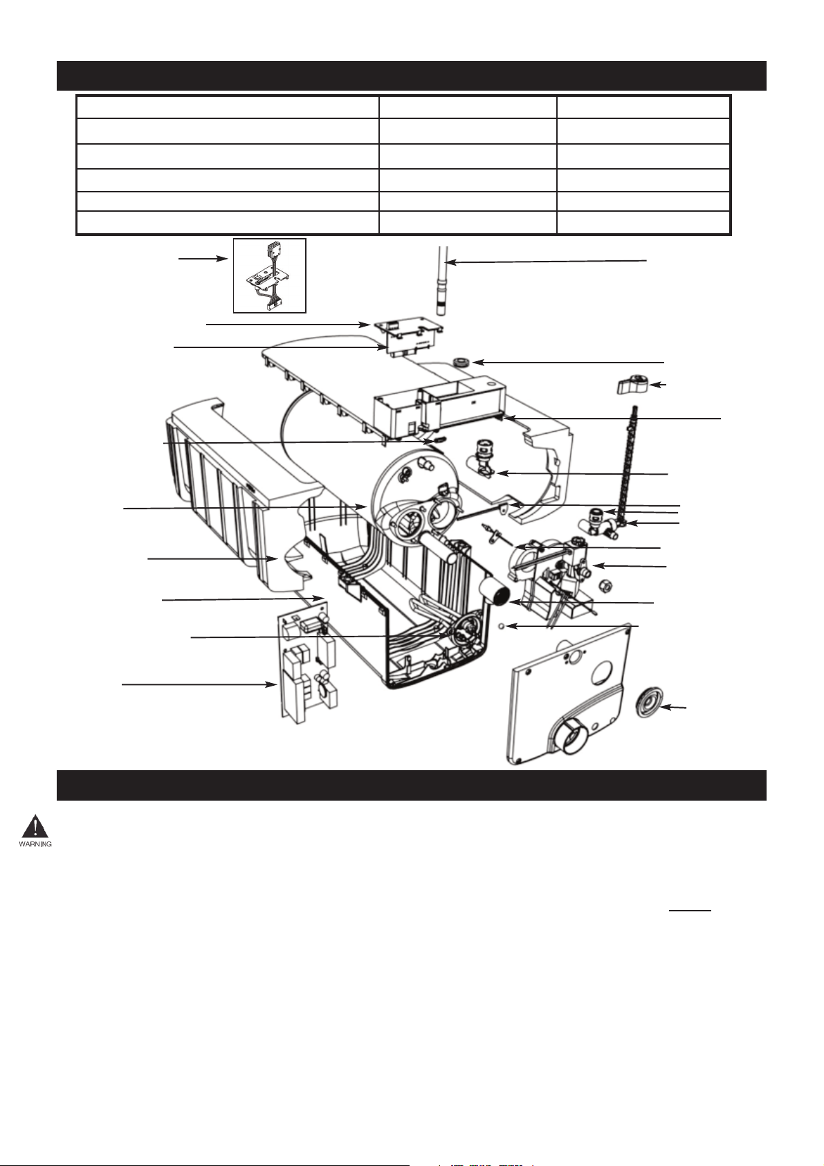
Braided Hose 12mm
Cold Inlet Seal
Drain Valve Lever
Box Lid
Cold Inlet 12mm
Hot Elbow 12mm
Pressure Relief
Overheat Stat
Control Thermistor
Burner Assembly
Flue Seal Bush
Condensate Drain Ball
Solenoid Seal
PCB
Electric Elements
Tank Casing
Insulation
Tank
Cable Clamp
Wireless PCB
Wireless PCB Cover
Fig.1 Components Drawing
6. INSTRUCTIONS FOR INSTALLATION
Note DW models:
A reset module is supplied
instead of a wireless PCB

6
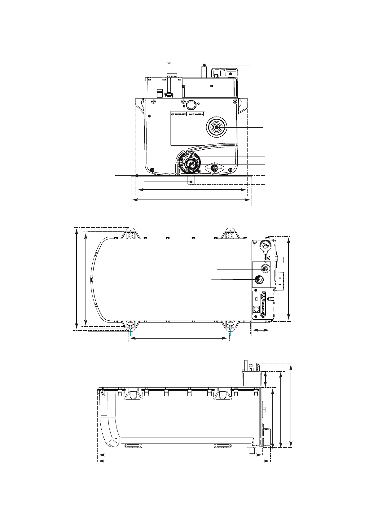
Fig. 2 Dimensions – Front View Underfloor
Fig. 3 Dimensions – Plan View Underfloor
DIMENSIONS
Underfloor Models
Whale Part Number: WW0801U (Suffix: B or R or C) or IW0801U (Suffix: B or R or C) or DW0801U (Suffix: R)
Fig. 4 Dimensions – Side View Underfloor
262mm
216mm
240mm
59mm 59mm
270mm
49mm
229mm
180mm
496mm
522mm
Cold Water In
Drain Lever / Pressure Relief Valve
Gas In
Exhaust Outlet
Cold Air Inlet
Water Heater
Mounting Point
Mounting Point
Hot Water Out
Cold Water In
7
Fig. 5 Dimensions – Front View Onboard
Fig. 6 Dimensions – Plan View Onboard
DIMENSIONS
Onboard Mounted Models
Whale Part Number: WW0801O (Suffix: B or R or C) or IW0801O (Suffix: B or R or C) or DW0801O (Suffix: R)
Fig. 7 Dimensions – Side View Onboard
262mm
232mm
60mm
270mm
49mm
229mm
180mm
496mm
522mm
Cold Water In
Drain Lever / Pressure Relief Valve
Gas In
Exhaust Outlet
Cold Air Inlet
Onboard Mounting Feet
Condensate Drain Pipe
Water Heater
18mm
280mm
252mm
Hot Water Out
Cold Water In
262mm
280mm

INSTALLATION INSTRUCTIONS - UNDERFLOOR MODELS
Whale Part Numbers: WW0801U (Suffix: B or R or C) or IW0801U (Suffix: B or R or C) or DW0801U (Suffix: R)
Step 1 Find Suitable Location For Water Heater Installation
Consider the following 9 points:
i. For weight distribution in caravans, the Water Heater must be positioned as close to the axle as
possible. The installer must avoid locating the Water Heater at the very rear and the very front of the
vehicle.
ii. The Water Heater must be located between chassis members to protect it from the curb.
The chosen location must ensure that the Water Heater is protected by chassis members which
must be at least 180mm deep.
iii. Any surfaces in contact with the Water Heater must be rated to at least 70 degrees C.
iv. The location must allow access for servicing the Water Heater.
v. The flue terminal must be located at the side of the caravan. Acceptable flue lengths are,
0.75 metres,1.25 metres and 2 metres.
vi. The flue terminal must be positioned at the side of the vehicle, that an awning will never be fitted to.
vii. Only the Whale flue terminal (supplied with this Water Heater) is permitted to be used in conjunction
with this Water Heater. This flue must not be positioned within 500mm of a refuelling point or fuel
tank breather outlet or any ventilator from the fuel system(s). The flue terminal must not be fitted
within 300mm of a ventilator for the living space or an opening part of a window.
viii. The flue terminal must only be positioned vertically below an opening part of a window, if the
appliance is fitted with an automatic shut-off device to prevent operation when the window is open.
The flue terminal must be a minimum of 300mm below the window.
ix. If supplied with a reset button, the user must have access to it in order to be able to clear some
lockouts.
Fig. 8 Installation Locating Diagram - Underfloor Installation
Step 2 Cut Out Hole for Underfloor Water Heater
The cut out in the floor and hole positions are shown in Fig. 9.
A cut out template is available on request by contacting Whale on +44 (0) 845 217 2933.
8
Fig. 9 Cut Out Hole in Floor - Underfloor Installation
Fuel refuelling
/ breather vent
PLEASE NOTE: Step i to ix
for information on Water
Heater and Flue Locations.
KEY
Prohibited area for
Water Heater flue
9mm Bolt Holes
9mm Bolt Holes
9mm Bolt Holes
9mm Bolt Holes
Cut Out In
Vehicle Floor
227.5mm
216mm
Min 500mm
INSTALLATION INSTRUCTIONS - UNDERFLOOR MODELS
Whale Part Numbers: WW0801U (Suffix: B or R or C) or IW0801U (Suffix: B or R or C) or DW0801U (Suffix: R)
The vehicle floor cut out must be reinforced with wooden batons (minimum 22mm wide, not supplied) around the
edge of the vehicle floor cut out. The floor in the area of the flat headmounting bolt holes must also have wooden
batons built in.
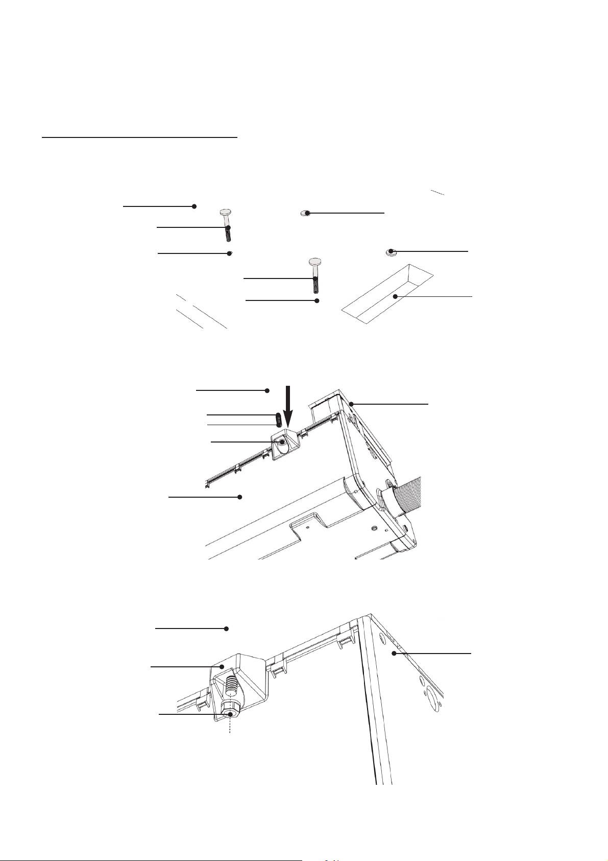
Step 3 Fit The Water Heater to The Floor
i. Insert 8mm flat head mounting bolts (not supplied) through the 9mm holes in the floor from the
inside, (as shown in Fig 10).
ii. Place the Water Heater on the underside of the vehicle floor. The mounting bolts must pass through
the mounting points, (as shown in Fig. 11).
iii. Secure the mounting bolts with M8 serrated flange head nuts (not supplied).
9
Fig.10 Fit Mounting Bolts
Fig. 11 Fit Water Heater
Fig. 12 Secure Bolts
8mm Bolt
8mm Bolt
Cut Out In
Vehicle Floor
9mm Bolt Holes
9mm Bolt Holes
Vehicle Floor
8mm Flathead Mounting Bolts
8mm Flathead Mounting Bolts
Cut Out In
Vehicle Floor
Flathead Mounting Bolts
9mm Bolt Holes
Mounting Points
Water Heater
Mounting Points
Water Heater
M8 Serrated Flange Head Nuts
Underside Vehicle Floor
Underside Vehicle Floor
 Loading...