

Page 1

Serien-Nr.:
Typenschild klein
Operating instructions
Automatic Wedge Welder
Wedge It PLUS
1/20 Ausgabe 01.2017/Rev.00 MUNSCH Kunststoff-Schweißtechnik GmbH
MUNSCH Kunststoff-Schweißtechnik GmbH
Im Staudchen D-56235 Ransbach-Baumbach
Tel.: +49 (0) 2623 898-80
Fax: +49 (0) 2623 898-85
E-Mail: [email protected]
http://munschwelding.com
Firmensitz/Registered Office: Im Staudchen, D-56235 Ransbach-Baumbach
Registergericht/Registration Court: Amtsgericht Montabaur, HRB 3959
Geschäftsführer/Managing Director: Stefan Munsch
Page 2
Introduction
Wedge It Plus, manufactured by MUNSCH Kunststoff-Schweißtechnik GmbH, is a selfpropelled, heat/pressure fusion machine, used for the seaming of thermoplastic geomembranes
and related materials.
Although this unit was designed for use in the field, it can be used in-house as well.
CAUTION
This machine is an electro-mechanical device with moving parts capable of exerting powerful force. Care
should be taken to prevent the accidental engagement of clothing, hair or personal extremities with any
moving parts.
MUNSCH Kunststoff-Schweißtechnik GmbH Ausgabe 01.2017/Rev.00 2/20
Page 3
Voltage
V
110/220
Frequency
HZ
50/60
Capacity
W
2000
Temperature
°C
Max. 450, infinitely variable
Max. travel speed
m/min
6.5, infinitely variable
Dimensions LxWxH
mm
406x279x267
Weight
kg
38.5
Materials
PE-HD (20-120),PP, Hypalon,
PVC (with stainless steel wedge), …
Material thicknesses
mm
0.5-2.5
Contents
Technical data: .............................................................................................................................................................. 3
Safety ............................................................................................................................................................................. 4
Identification ................................................................................................................................................................... 5
Key electrical controls ................................................................................................................................................ 5
Key mechanical components and functions .............................................................................................................. 5
Set-Up Procedure ...................................................................................................................................................... 7
Suggested set-up for HDPE material ......................................................................................................................... 8
Basic welding operation ............................................................................................................................................. 9
Executing a weld ........................................................................................................................................................ 9
Removing the Wedge-It at the end of the seam ...................................................................................................... 10
Welding procedure summary ................................................................................................................................... 10
Welding parameters – HDPE and LLDPE ............................................................................................................... 11
Maintenance ............................................................................................................................................................. 12
Lubricating gears, sprockets and chains.................................................................................................................. 13
Removing and reinstalling hot wedge assembly ...................................................................................................... 15
Re-Setting timing of rack & pinion wedge movement .............................................................................................. 16
Temperature alignment ............................................................................................................................................ 16
General information .................................................................................................................................................. 17
Key internal electronic components ..................................................................................................................... 17
Main spare part list ............................................................................................................................................... 18
Changing operating voltage of Wedge-It .............................................................................................................. 19
Troubleshooting chart .............................................................................................................................................. 19
EC-Declaration of Conformity by the Manufacturer ..................................................................................................... 20
Note: These operating instructions must always be available to the machine operators.
Make sure to read them carefully before placing the unit in service.
Very important!
Switch off the heating wedge whenever the unit is out of service for prolonged periods.
This will prevent heating up of the machine due to radiating heat. Otherwise some machine
components may develop high surface temperatures.
Additional cooling of the heating wedge is not allowed
(water, chilling agents or similar)
3/20 Ausgabe 01.2017/Rev.00 MUNSCH Kunststoff-Schweißtechnik GmbH
Technical data:
Page 4
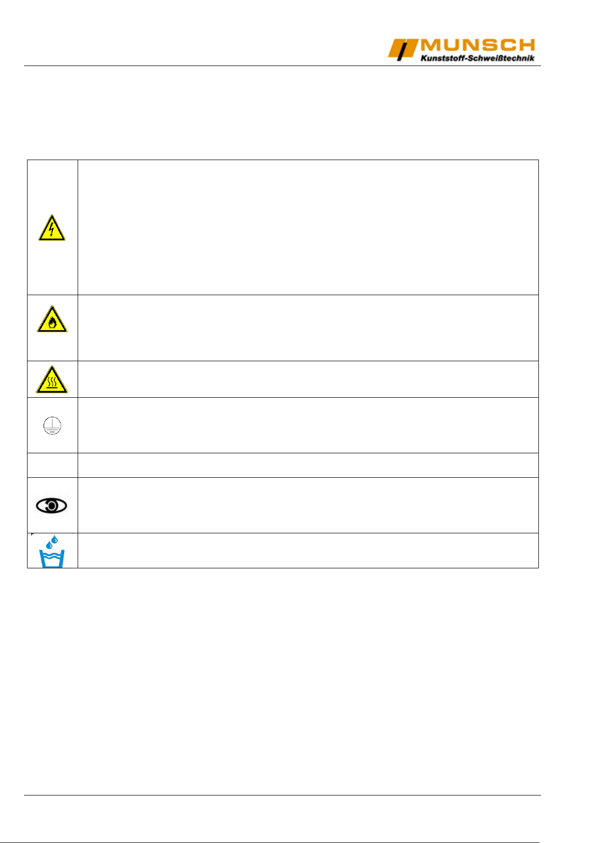
Danger to life when opening the unit due to exposure to live components. Disconnect the power supply (all poles) before opening the unit. A damaged connecting
cable may cause fatal electrical shock. The rated voltage indicated on the unit type
tag must match the mains voltage. If required, check with your electric utility.
Improper use of the welding unit poses a fire and explosion hazard, especially when
working in the vicinity of flammable materials and explosive gases.
Not suitable for use in explosion hazard areas!!!
Risk of burns!!!
Do not touch the heating wedge when hot. Always allow unit to cool down.
Protection Class I equipment
Connect the unit only to power outlets equipped with a protective conductor. Each
interruption of the protective conductor presents a hazard. Only use extension cables with the correct conductor cross-section and a protective conductor.
FI
FI switch required for personal protection.
Unit may only be operated under observation. Heat may propagate to flammable
materials outside the range of vision.
Protect the unit from moisture and direct rainfall!
Safety
MUNSCH Kunststoff-Schweißtechnik GmbH Ausgabe 01.2017/Rev.00 4/20
Page 5

Motor
Speed
Control
On/Off
Switch
(Motor)
Speed Readout
Temperature Control
Heating
Element
Indicator
Lights
On/Off Switch
(Temperature)
Nip Pressure
Cam Lever
Lock-in Plate
Wedge Movement Handle
Retract Plunger
Lower Nip
Roller
Upper Nip
Roller
Nip Pressure
Cam
Identification
Key electrical controls
Fig.1
Key mechanical components and functions
Fig. 2
5/20 Ausgabe 01.2017/Rev.00 MUNSCH Kunststoff-Schweißtechnik GmbH
Page 6

Wedge
Upper Contour
Roller Assy
Upper Contour
Roller Adjustment
Lower Contour
Roller Adjustment
Cover
Wedge Up/Down
Centering Adjustment
Drop Out Plate
Lower Contour
Roller Assy
Fig. 3
Fig. 4
MUNSCH Kunststoff-Schweißtechnik GmbH Ausgabe 01.2017/Rev.00 6/20
Page 7

Set-Up Procedure
Initial Set-up – Various mil thickness tolerances:
The initial set-up of the Wedge-It is by far the most critical aspect of not only quality welding results, but also wear
and tear on the unit itself.
Adjusting the Wedge-It too tightly can result in excessive wear on drive-train parts, such as gears, chains and
sprockets, etc.
The recommended Set-Up Procedure before heating up the unit is as follows:
From the same mil thickness material as that to be welded, cut 2 pieces app. 4x18” (ca. 100 x 450mm) and 2 small-
er pieces app. ½ x 2” (ca. 13 x 50mm). These 4 pieces of material will be used as „gauges“, for setting the 3 adjustments.
Adjustment 1: Wedge Centering
Place the two smaller pieces of material, each folded in half, between the two nip rollers (figure 2). This is to simu-
late 2 layers of material between the rollers. Be sure these pieces do not extend past the Nip Rollers into the machine. Rotate the Nip Pressure Cam to do first positioning by rotating the Nip Pressure Cam Lever clockwise, until
reaching the mark showing the thickness of your welding sheet.
Move the wedge (figure 4) to the engaged position by rotating the wedge movement handle (figure 2) counterclockwise. Adjust the wedge with a 5mm hex wrench by turning the centering adjustment, so that the wedge gets into the
centered between upper and lower nip roller.
Adjustment 2: Wedge forward travel
This adjustment determines how close the wedge is to the nip rollers when it is in the engaged or welding position.
To set clearance, pull out the wedge retract plunger on the wedge movement handle (figure 2), rotate the handle to
a central position between the hold down screws (figure 2), loosen the screws and rotate the handle counterclockwise until the retract plunger drops into the lock-in hole.
NOTE: The distance from the upper tip of the wedge to the upper nip roller should be the same distance as between
the two nip rollers. This same clearance should also be maintained between the lower tip of the wedge and the lower nip roller.
To lock down the setting, hold down the wedge lock-in plate, pull the retract plunger out, and rotate the handle to
central location between hold-down screws (figure 2). Tighten hold-down screws and move lock-in plunger back to
lock-in hole.
Adjustment 3: Upper and lower contour rollers
Remove the lower contour roller adjustment cover, to expose the adjustment. With a 10mm box end wrench, loosen
the lock-nut. With ad 3mm hex wrench, back off the adjustment until it bottoms out.
With a 10mm wrench, loosen the lock-nut on the upper contour roller adjustment (figure 4). Turn the adjustment
counter-clockwise, raising the upper contour roller assembly out of the way.
With the wedge locked into the engaged position, and the ½ x 2” pieces of material still between the nip rollers, you
are ready to make adjustments.
Insert one of the 4” x 18” pieces of material between the lower contour roller assembly and the wedge. This piece
should extend out of the front of the machine (opposite end from the nip rollers).
Adjust the lower contour rollers up, clockwise, until the wedge begins to move up slightly. Now insert the other 4” x
18” piece of material between upper contour assembly and wedge (figure 4). Adjust the upper contour rollers down,
clockwise, to obtain the desired tolerance.
7/20 Ausgabe 01.2017/Rev.00 MUNSCH Kunststoff-Schweißtechnik GmbH
Page 8
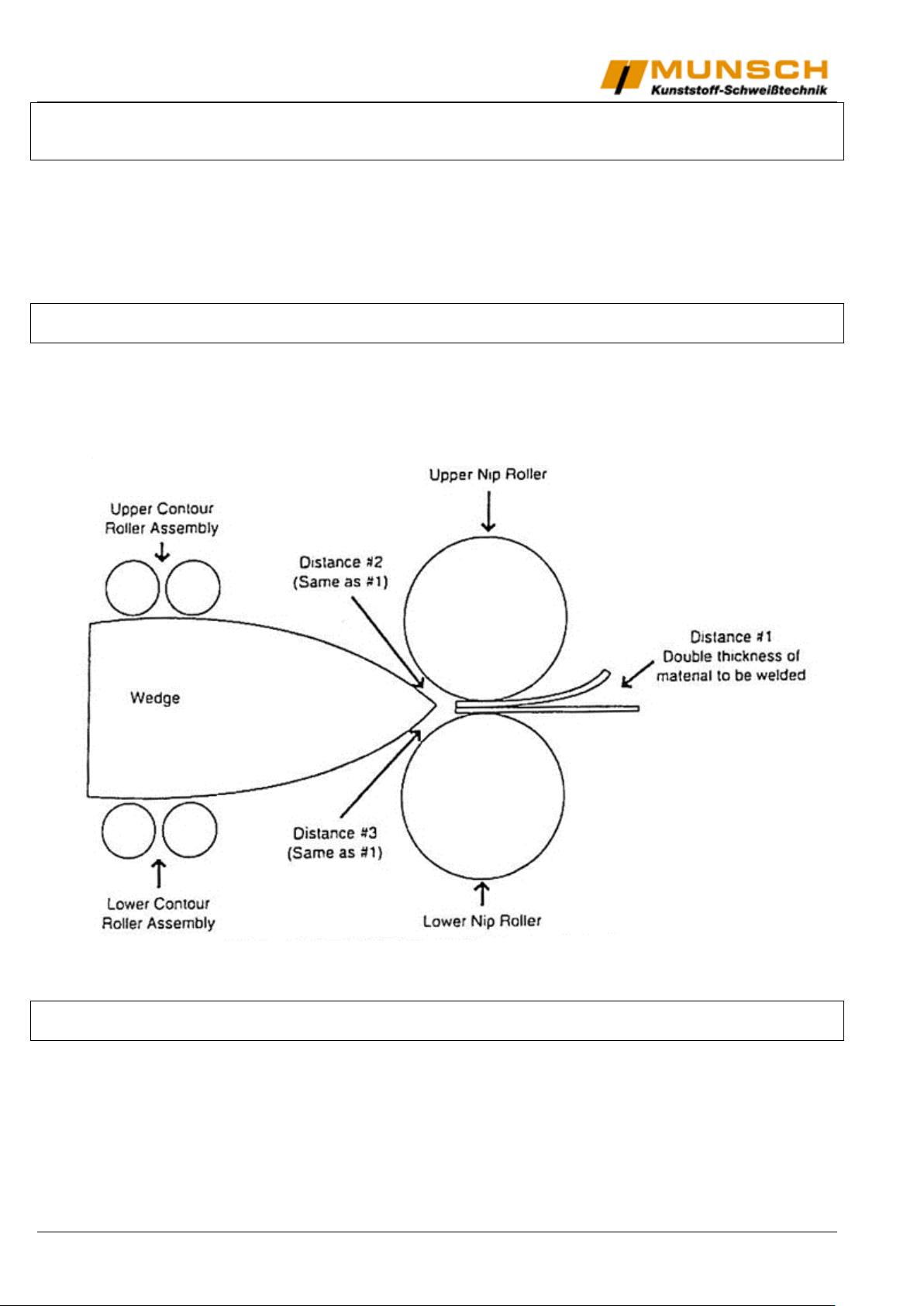
NOTE: This hold be a “snug fit”. To check, hold onto the upper piece of material at the front end of the machine and
move it forward and backward. Check the lower adjustment the same way. Now, make sure the tip of the wedge is
still centered between the nip rollers.
Once the desired tolerance is set, tighten both the upper and lower lock-nuts, being careful not to tighten them too
much.
Replace lower contour roller adjustment cover.
Remove all pieces of material.
NOTE: Although this procedure may appear time consuming at first, with a little practice, the entire set-up should
only take a few minutes.
Suggested set-up for HDPE material
NOTE: Distances #1, 2 & 3 should be the same for the HDPE set-up. For PVC set-up, distance #2 & 3 should be
approximately ½ the distance of #1 and contour roller adjustments should be backed off completely or removed.
MUNSCH Kunststoff-Schweißtechnik GmbH Ausgabe 01.2017/Rev.00 8/20
Page 9
1
2 3 4
5
6
Basic welding operation
Heating up the wedge:
Please plug the power cord to the Power supply (110V or 220V, depending on the configuration of Wedge It).
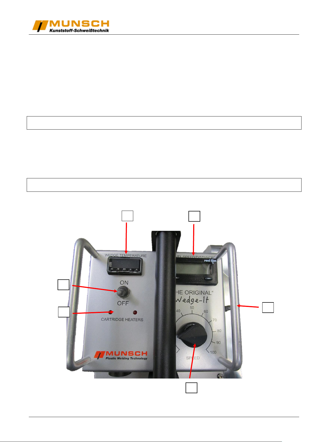
Turn on the switch for temperature (5). Temperature will now show actual temperature (4) and alarm will sound, if
the motor is switched on.
Set the desired temperature and wait until the machine reaches the set point.
Turn on the motor.
If you want, you can now reset the passed distance.
NOTE: Temperature display is in degrees FAHRENHEIT, unless otherwise specified. Recommended temperature
settings can be found on page 13 of this manual.
Whether you are welding small sample pieces, or large sheets, the loading of the material will be the same with the
nip rollers and wedge in the disengaged position and motor switch off.
Position the Wedge-It in the seam, inserting first the bottom sheet of material under the wedge and between the nip
rollers, and then the top sheet of material over the wedge and between the nip rollers. Sheet overlap should be
approximately 5 to 6 inches.
NOTE: Once the bottom sheet of material has been loaded, you may need to manually roll the welder forward and
backward as you are loading the top sheet to prevent a “burn out” at the beginning of the weld.
9/20 Ausgabe 01.2017/Rev.00 MUNSCH Kunststoff-Schweißtechnik GmbH
Page 10

Executing a weld
First position (click)
=
100 mil setting
Second position (click)
=
80 mil setting
Third position (click)
=
60 mil setting
Fourth position (click)
=
40 mil setting
Fifth position (click)
=
20 & 30 mil setting
Please engage the welding pressure by rotating the nip pressure cam lever (9) clockwise to the desired pressure
setting for the thickness of the material that is going to be welded.
The following nip pressure cam positions (15) will help you in achieving the desired pressure:
Now turn on the switch of the motor (2) and rotate the motor speed control (1) to achieve the desired travel speed
(table on page 11). Speed readout (3) should be displaying the current travel speed.
NOTE: The speed at which the Wedge-It must travel to produce a quality weld will vary according to the mil thickness of the material being welded, the temperature of the wedge, the ambient temperature, the temperature of the
welding material, etc. All of these variables must be taken into consideration when choosing a speed setting.
As soon as the Wedge-It begins to travel, rotate the wedge movement handle (12) counter clockwise until the
wedge retract plunger drops into the lock-in plate hole. This should take little or no effort on the part of the operator.
If it does, the wedge has been set too close to the nip rollers and has to be re-adjusted (see page 6).
Removing the Wedge-It at the end of the seam
As soon as the nip rollers have reached the end of the seam, extract the Wedge-It in the following order:
1. Disengage nip rollers pressure
2. Turn the motor switch off
3. Disengage the wedge by pulling out the ring on the wedge retract plunger (10) and by rotating the wedge
movement handle (12) clockwise.
Welding procedure summary
Starting the weld
1. Turn the motor switch on
2. Engage the welding pressure
3. Engage the wedge
Ending the weld
1. Disengage the welding pressure
2. Turn the motor switch off
3. Disengage the wedge
REMEMBER: Always engage the wedge LAST when starting a weld and disengage the wedge LAST at the end of
the weld.
MUNSCH Kunststoff-Schweißtechnik GmbH Ausgabe 01.2017/Rev.00 10/20
Page 11
Material
Wedge Temperature
Speed
Pressure setting
Nurled steel nip
rollers
Silicon rubber nip
rollers
HDPE
20mil
660°F
350°C
18 ft/min
---
20, 30, 40 mil
30mil
660°F
350°C
16.5 ft/min
20, 30, 40 mil
20, 30, 40 mil
40mil
660°F
350°C
13.5 ft/min
40, 60 mil
40, 60 mil
60mil
700°F
370°C
10.5 ft/min
60 mil
---
80mil
700°F
370°C
7.5 ft/min
80 mil
---
100mil
700°F
370°C
4.5-6 ft/min
80, 100 mil
---
120mil
700°F
370°C
3-4.5 ft/min
80, 100 mil
---
LLDPE
20mil
620°F
326°C
18 ft/min
---
40, 60 mil
30mil
620°F
326°C
16.5 ft/min
---
40, 60 mil
40mil
640°F
337°C
13.5 ft/min
---
40 mil
60mil
660°F
350°C
7.5 ft/min
80 mil
80 mil
PVC, Hypalon, XR5,
Polypro, etc.
625°F
285°C
9 ft/min
---
40, 60 mil
Material
Welding
Temp
Welding Speed
Steel Rollers
Rubber Rollers
HDPE 0,5mm
400 C
3 to 4,5 m/min
Yes
HDPE 0,75mm
400 C
3 to 4m/min
Yes
HDPE 1,0mm
450 C
2,4 to 3,6 m/min
Yes
LLDPE 0,5mm
380 C
3,6 to 5,4 m/min
Yes
LLDPE 0,75mm
380 C
3,6 to 4,8
m/min
Yes
LLDPE 1,0mm
400 C
3 to 4,2 m/min
Yes
PE/LDPE Coated Fabric 0,3mm
350 C
6 to 9m/min
Yes
PE/LDPE Coated Fabric 0,5mm
380 C
4,5 to 7,5m/min
Yes
PE/LDPE Coated Fabric 0,75mm
380 C
3,6 to 6m/min
Yes
Non-Supported PVC 0,3mm
400 C
3 to 4,8m/min
Yes
Non-Supported PVC 0,5mm
400 C
2,4 to 4,2 m/min
Yes
Non-Supported PVC 0,75mm
450 C
2,4 to 3,6m/min
Yes
PVC Coated Fabric 0,3mm
380 C
6 to 10,5m/min
Yes
PVC Coated Fabric 0,5mm
400 C
6 to 9,6 m/min
Yes
PVC Coated Fabric 0,75mm
450 C
5,4 to 9 m/min
Yes
RPP(Reinforced Polypropylene)
0,9mm
400 C
2,4 to 4,2 m/min
Yes
RPP(Reinforced Polypropylene)
1,2mm
450 C
2,4 to 3,6m/min
Yes
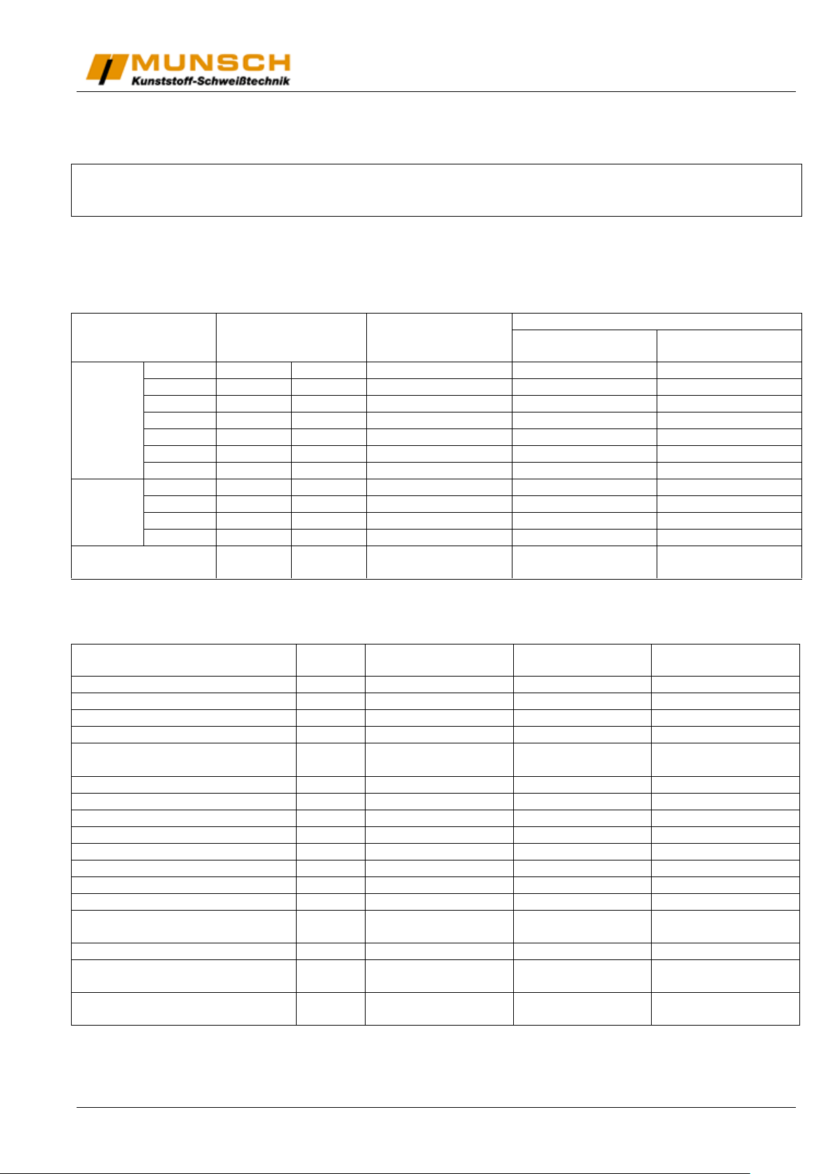
Welding parameters – HDPE and LLDPE
NOTE: The parameters listed below are only suggested starting points to be used when making a “prequalifiying”
sample weld. As ambient conditions and other variables change (i.e. dirt, moisture, etc.), the welding parameters
must be adjusted by the field technician or by the operator.
MUNSCH Kunststoff-Schweißtechnik GmbH assumes no liability for weld quality or lack thereof, when using a
Wedge-It Hot Wedge Welder.
Imperial Parameters:
All parameters above are specified for use with a split wedge (with air channel) and split steel or rubber Nip Rollers.
Metric Parameters:
11/20 Ausgabe 01.2017/Rev.00 MUNSCH Kunststoff-Schweißtechnik GmbH
Page 12

Maintenance
(Only for qualified personnel)
This section presents maintenance information for the Wedge-It, including preventive maintenance tips, troubleshooting, and other general information.
WARNING
These service instructions are for use by qualified personnel only. To avoid personal harm, or damage to the machine, do not perform any procedures in this section unless you are qualified to do so.
REMEMBER
In any cases you need help, please call us: +49-2623-898-80 or your dealer.
Preventive maintenance tips
Keeping your Wedge-It clean is the most important factor in prolonging the life of the unit. Simple cleaning practices,
such as brushing off the hot wedge and removing small rocks and dirt or mud from lower contour roller area, should
be performed after each seam is completed.
More involved maintenance practices should be performed on a daily or weekly basis, depending on how much
welding you are doing. Part 1 of this section will explain how to accomplish these tasks.
MUNSCH Kunststoff-Schweißtechnik GmbH Ausgabe 01.2017/Rev.00 12/20
Page 13
30
31
32
PART 1
Lubricating gears, sprockets and chains
WARNING: To prevent electronic shock and other bodily harm, make sure unit is unplugged.
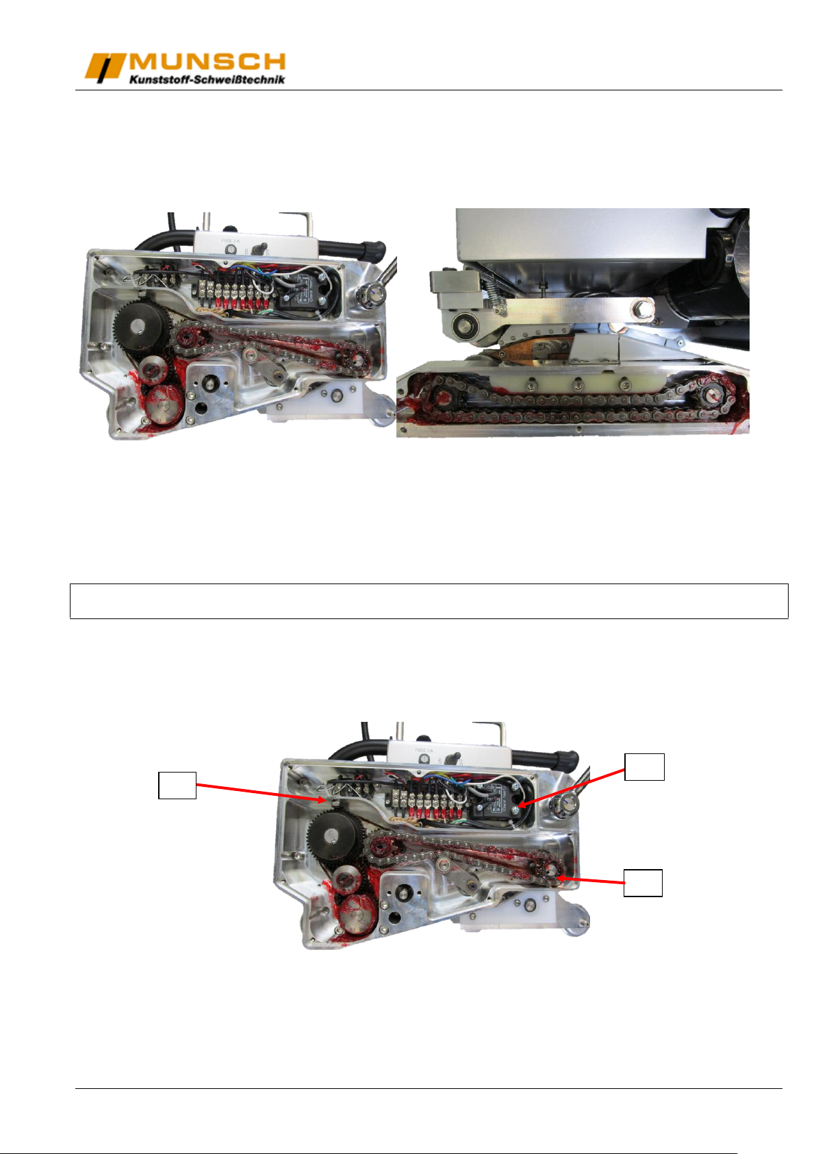
a. Remove the drive-side cover to expose main drive mechanism and main wiring terminal (left figure). The
wedge movement handle and adjustment plate will need to be removed for this. Also remove the lower
drive chain cover on opposite side to expose lower drive chain (right figure).
b. Clean all gears, sprockets and chains with brake cleaner or cleaning solvent of your choice and a parts
brush. Wipe with a clean rag, or preferably, blow dry with compressed air. Make sure all components are
clear of dirt and sand, etc. Lightly lubricate all gears, sprockets and chains.
NOTE: MUNSCH Kunststoff-Schweißtechnik GmbH recommends using spray on white lithium grease which is
available at any hardware store or auto parts store.
c. Check chains for proper adjustment and all shoulder bolts, set screws and retaining rings for tightness, in-
cluding wiring terminal screws.
d. Replace both side covers and wipe down the rest of the unit with a clean rag. Check all other screws and
retaining rings on the machine for tightness.
30. Upper Nip Sprocket Snap Ring
31. Solid State Relais
32. Magnetic Pick-up
13/20 Ausgabe 01.2017/Rev.00 MUNSCH Kunststoff-Schweißtechnik GmbH
Page 14
33
34
36
35
37
38
39
40
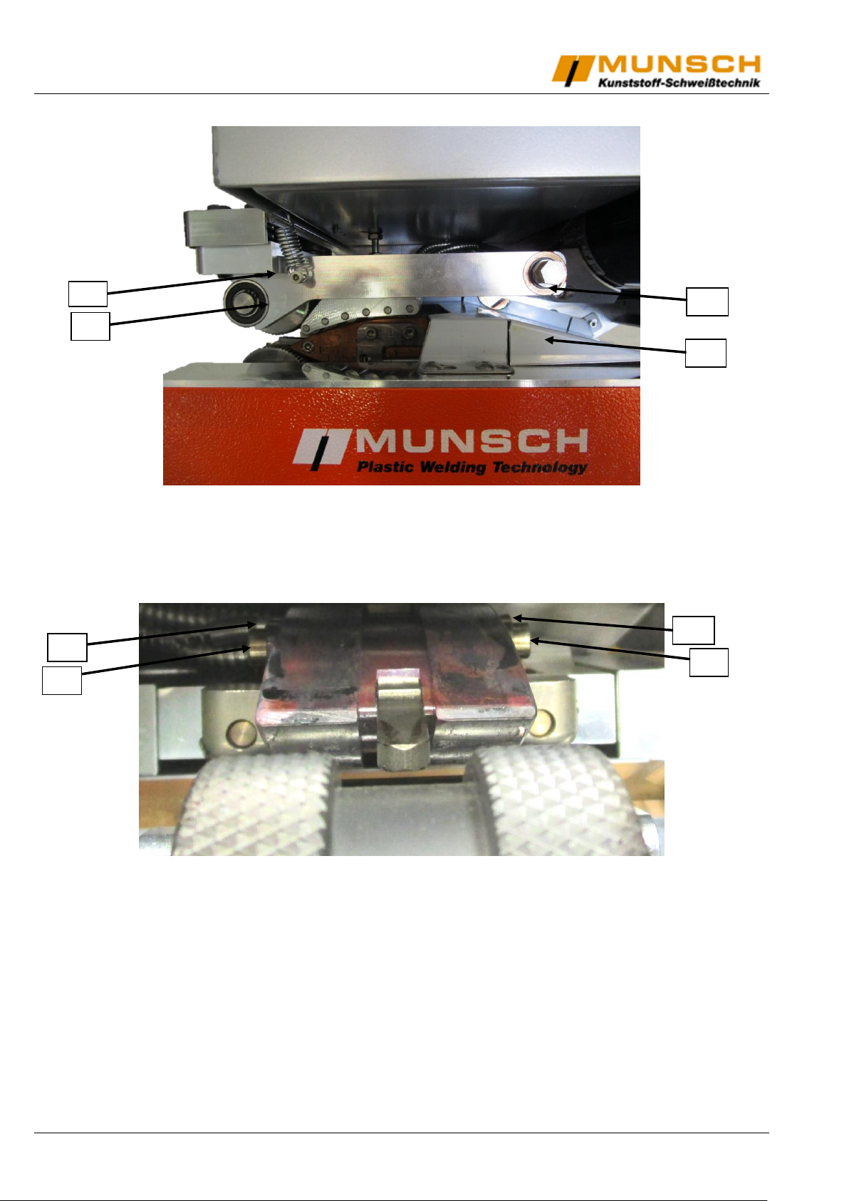
33. Nip arm
34. Nip arm spring
35. Upper material guide
36. Nip pivot shaft snap ring
37. Wedge mount set screw
38. Linear shaft
39. Wedge mount set screw
40. Linear shaft
MUNSCH Kunststoff-Schweißtechnik GmbH Ausgabe 01.2017/Rev.00 14/20
Page 15
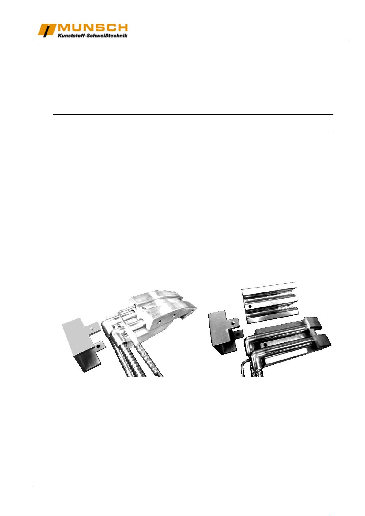
Removing and reinstalling hot wedge assembly
(to replace burnt heating cartridges, thermocouple, etc.)
a. Remove the wedge movement handle, the lock-in plate, and the side cover, to expose the main drive
mechanism and the main wiring terminal (see page 12).
b. Disconnect the thermocouple and the heating cartridge wires from the terminal block.
NOTE: The main terminal block is numbered 1-9, starting from the left side. The thermocouple is
connected to terminal 1 & 2, the heating cartridge wires are connected to terminals 3 to 6.
c. Remove the upper nip sprocket snap ring (30) and slide the sprocket off the shaft.
d. Proceed to the other side of the welder. Please disconnect the nip arm spring (34) from the nip arm and re-
move the nip pivot shaft snap ring (36).
e. Now remove the nip arm (33) from the welder by sliding it off the nip pivot shaft. You can now inxpect and
clean the upper contour roller assembly.
f. Please remove the upper material guide (35) to further expose the hot wedge assembly.
g. Remove the wedge mount set screws (37 & 39) and tap the linear shafts (38 & 40) back through the wedge
mount.
h. After gently guiding the heater and the thermocouple wires through the side frame hole, extract the wedge
assembly by carefully lifting up and out over lower nip roller.
(Now the wedge assembly is ready for cleaning, servicing, replacement, etc.)
i. To replace the wedge assembly, follow steps a-h in reverse order. Make sure the heating cartridge and the
thermocouple wires are tucked neatly between the upper material guide and the side frame. Also, make
sure that there is enough slack in these wires to allow free fore and aft movement of the wedge.
j. Split copper wedge makes changing the heaters simple.
15/20 Ausgabe 01.2017/Rev.00 MUNSCH Kunststoff-Schweißtechnik GmbH
Page 16
Re-Setting timing of rack & pinion wedge movement
Often when removing and reinstalling hot wedge assembly, the relationship of the lock-in plate / wedge
movement handle to the for / aft position of the wedge itself will be off slightly. This can be corrected by proceeding with the following steps.
A. With lock- in plate hold down screws loose, rotate wedge movement handle counter-clockwise moving
wedge back as close to nip rollers as possible.
B. Insert screwdriver through access slot at the front of the welder between the upper material guide and
the front travel roller. Gently press downwards on the end of the rack gear. This will release mesh between rack gear and pinion gear.
C. With roller gear still depressed, rotate the wedge movement handle until it is as close to horizontal as
possible and so that the lock-in plunger is in the lock-in hole.
D. Remove the screwdriver and check the wedge movement to make sure the rand and the pinion gears
are meshing properly.
E. Re-set the welding tolerances (see set-up section of this manual).
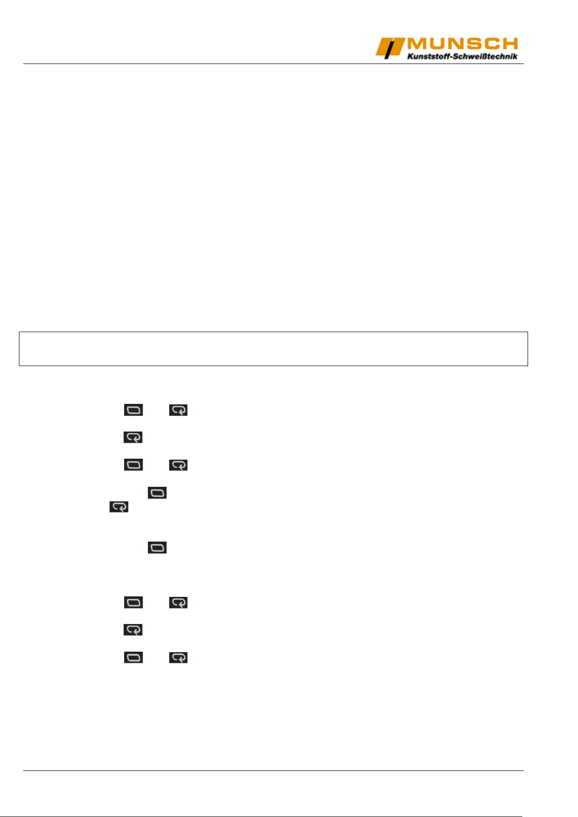
Temperature alignment
Please follow the mentioned steps carefully!
Not following the instructions may harm the machine!
1. Set the desired temperature
2. Unlock the controller:
a. Keep and pushed until oATP appears.
b. Set it to „0“
c. Push 1 x: iCPt appears
d. Set it to „0“
e. Keep and pushed until the screen changes.
3. Evaluate the difference between set temperature and real temperature, using a probe.
4. Shortly push : L.Adj appears
5. Push 2 x: iN-S appears
6. Set the difference. If the wedge is hotter than set, higher the value by the evaluated
difference. If it is cooler, lower the value.
7. Shortly push
8. Restart at number 3 and repeat steps 4 and following, until temperature is within a
3°C tolerance.
9. Lock the controller:
a. Keep and pushed until oATP appears.
b. Set it to „2“
c. Push 1 x: iCPt appears
d. Set it to „2“
e. Keep and pushed until the screen changes.
In case of any questions, please call your sales office or dial MUNSCH at: +49 2623-898-80
MUNSCH Kunststoff-Schweißtechnik GmbH Ausgabe 01.2017/Rev.00 16/20
Page 17
E30
E14
E6
E15
E15
E16
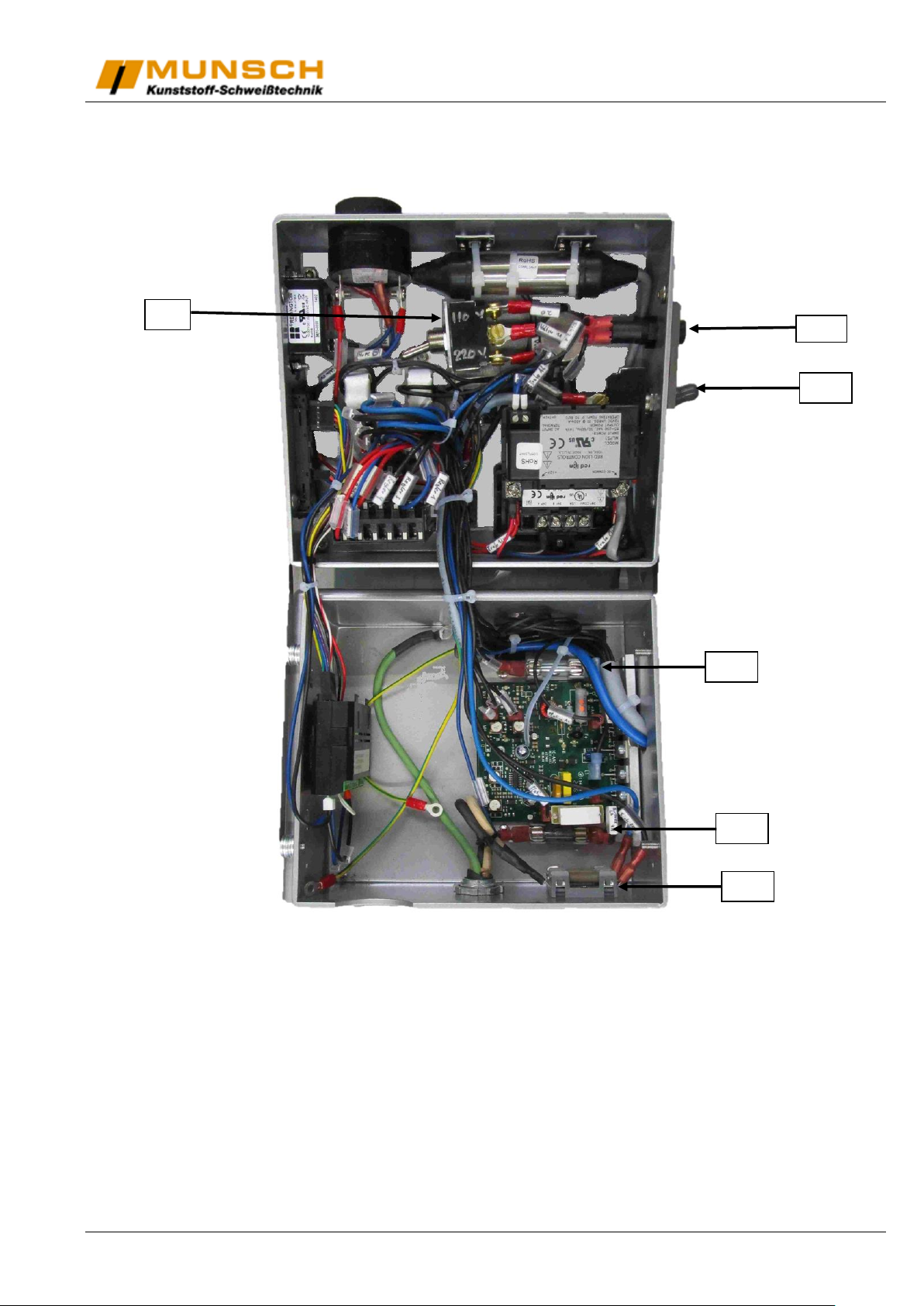
General information
Key internal electronic components
E6 – Main operating Voltage Selection Switch
E14 – Motor Current Fuse (2A)
E15 – Motor Board Fuses (4A, 2 pieces)
E16 – Main Line Fuses (20A, 2 pieces)
E30 – Speed Readout Voltage Selection Switch (Motor power switch)
NOTE: To access key electronic components shown above, the top handle, handle brackets and
lid screws have to be removed.
17/20 Ausgabe 01.2017/Rev.00 MUNSCH Kunststoff-Schweißtechnik GmbH
Page 18
Description
Munsch ordering code
Temperature controller
K02187
Heating cartidge 800W
K02878
Heating cartridge 1000W
K06893
Heating cartridge 5/8“ 1000W
K07011
Thermocouple
K02879
Solid State relais
K06462
Hot wedge
K06355
Motor control board
K06549
Plug in horse power resistor
K06477
Chain main frame
K06424
Chain side frame
K06509
Contour roller small (PLUS)
K07013
Bearing for contour roller (PLUS)
K07012
Contour roller large (series 2000)
K02993
Bearing for contour roller (series 2000)
K02994
Split steel nip roller
K02865
Steel nip roller
K06363
Split rubber roller (Outrigger needed)
K06364
Split rubber roller PVC (Outrigger needed)
K06367
Rubber roller (Outrigger needed)
K05844
Outrigger for fixing rubber roller
K06236
Teflon skid
K05260
Magnetic pick-up
K06479
Speed read out
K06482
Power supply
K06460
Hour meter
K06474
Voltmeter
K06476
Speed potentiometer
K06478
Speed knob
K06471
Speed knob locker
K06472
Voltage selection switch 110V-220V
K06470
Motor / Temperature switch
K06468
Amplifier
K06481
Sone alert
K06473
Heating LED
K06457
Main spare part list
MUNSCH Kunststoff-Schweißtechnik GmbH Ausgabe 01.2017/Rev.00 18/20
Page 19
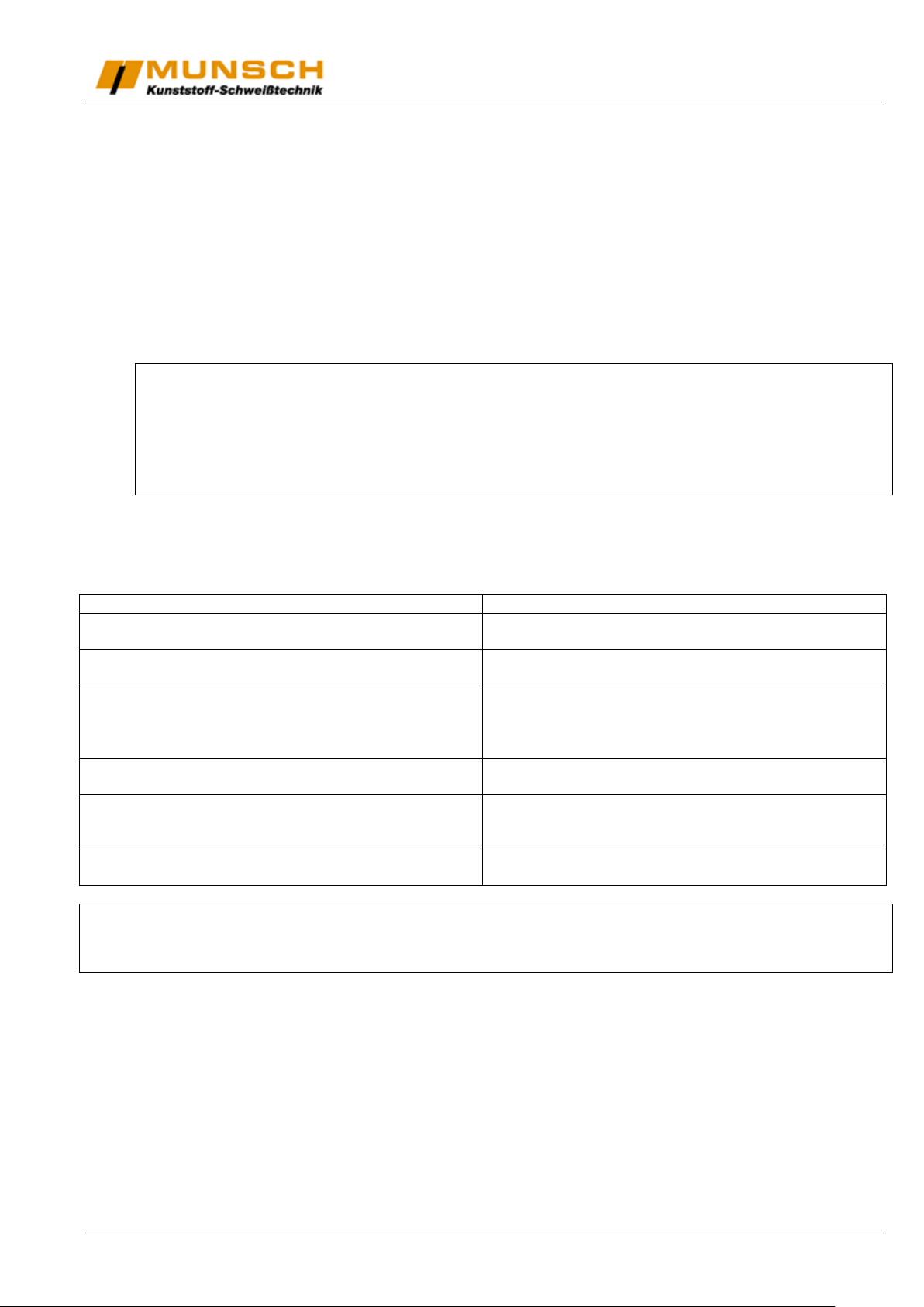
Symptom
Problem and / or remedy
No power supplied to the wedge
Check power cord and power supply
Check main fuses (E16)
Wedge will not heat up
Check temperature setting
If setting is correct, please contact us
Wedge does not stop heating (runaway temperature)
Turn power of wedge off before reaching 900°F (482°C)
to avoid damage to the wedge or other elements.
Possibly solid state relais or temperature control are
damaged.
Temperature drops down during weld and does not
catch up
Heating elements or relais or temperature control are
defective.
Nip rollers do not rotate
Check motor on/off switch.
Check motor speed setting.
Check motor fuses (E14, E15)
Upper nip rollers rotate, lower nip rollers don’t rotate
Check both nip roller set screws for tightness
Check drive chains & sprockets.
Changing operating voltage of Wedge-It
In cases we do not know voltage of your country, we deliver Wedge It with configuration 220V.
Otherwise we will set it to the Country’s voltage (110V or 220V).
To change the preset voltage, please proceed as follows:
1. Access the electronic box. Therefore demount big handle and the two handle brackets.
2. Open the electronic box and switch main operating voltage selection switch (E6) to the desired voltage
(110V or 220V).
3. Remount all demounted items.
CAUTION!
Do not plug Wedge it to 220V when set to 110V!!!
This will cause serious damage on the machine!
Troubleshooting chart
NOTE:
Parts list is not included to this instruction manual.
If you need item numbers, prices and delivery times, please contact your distributor.
19/20 Ausgabe 01.2017/Rev.00 MUNSCH Kunststoff-Schweißtechnik GmbH
Page 20
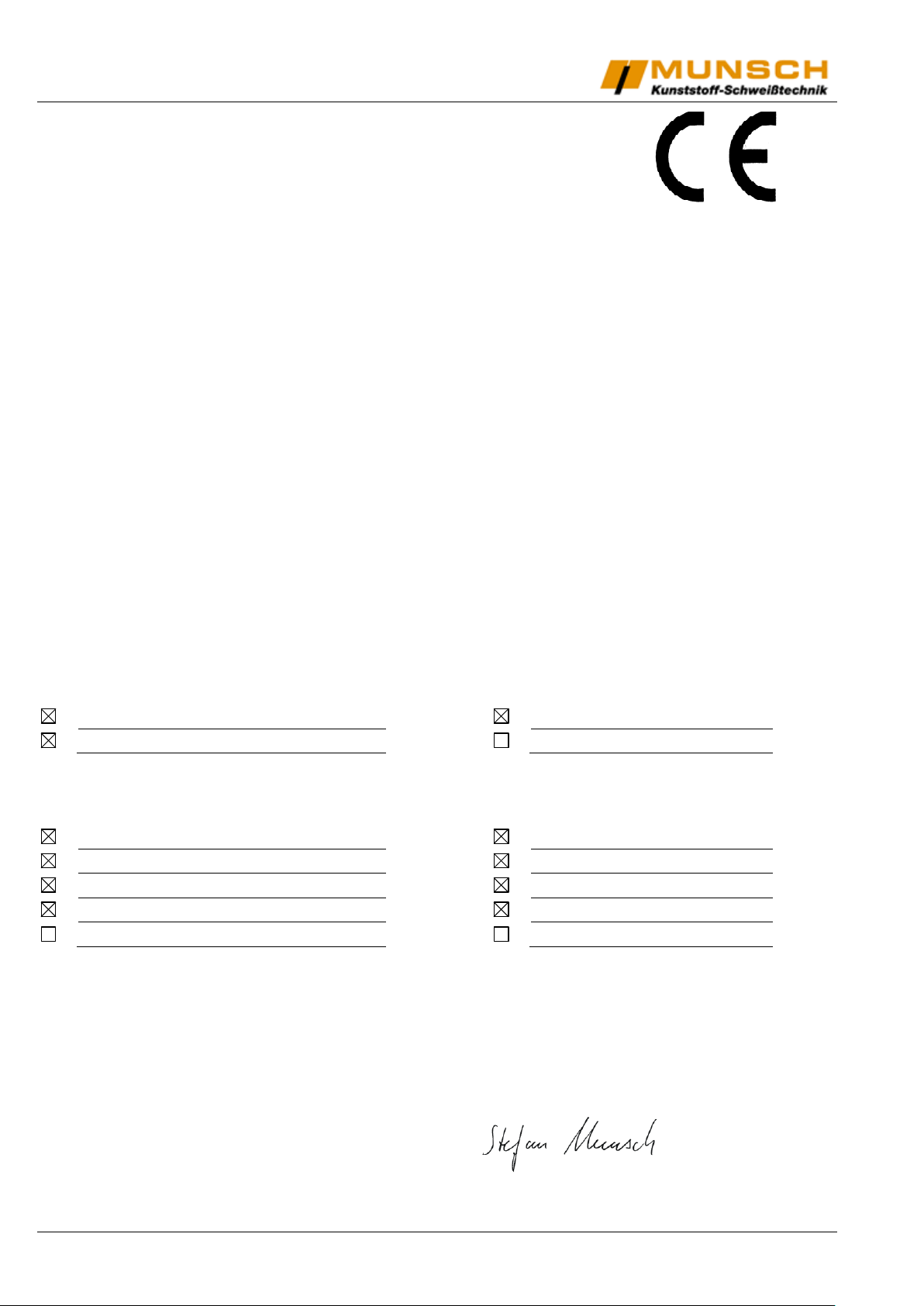
Machine type:
Wedge welder
Wedge welder
Wedge welder
Wedge welder
Type designation:
WEDGE-IT-MICRO
WEDGE-IT-PLUS
WEDGE-IT-LE
WEDGE-IT-MULTI
WEDGE-IT-ECO
EU Machinery Directive 2006/42/EC
DIN EN 13732-1: 2008
DIN EN ISO 12100: 2010
EU Low-Voltage Directive 73/23/EC
EU EMC Directive 89/336/EC
EN 60204-1 (VDE 0113 Part 1): 2011
DIN EN 55014-1: 2012
EN 61029-1 (VDE 0740 Part 500): 2010
DIN EN 55014-2: 2009
DIN EN 62638
EN 61000-4-11:2004
EG-Konformitätserklärung des Herstellers
nach der EG-Maschinenrichtlinie 2006/42/EG Anhang II, Nr. 1 A
EC-Declaration of Conformity by the Manufacturer
as defined by machinery directive 2006/42/EC, Annex II, No. 1 A
MUNSCH Kunststoff-Schweißtechnik GmbH
Im Staudchen
D-56235 Ransbach-Baumbach
Germany
Mr. Johann Dausenau,
Kunststoffschweißtechnik GmbH,
is authorised to compile the technical documentation.
We hereby declare that the wedge welders
are in accordance with all relevant provisions of the EC Machinery Directive.
The following harmonised standards (or parts of these standards) were applied:
The wedge welders are in accordance with the following EC-directives:
This industrial tool complies with the aforesaid standards insofar as it is used at the contractually agreed
conditions. The operator is responsible for this.
In the event of any modifications to the machine/unit or use not as intended, this declaration becomes invalid
unless the manufacturer’s prior written approval has expressly been given.
Ransbach-Baumbach, 21.11.2014 Dipl.-Ing. Stefan Munsch
Managing Director
MUNSCH Kunststoff-Schweißtechnik GmbH Ausgabe 01.2017/Rev.00 20/20
 Loading...