


0
Operating Instructions
Automatic Wedge Welder
Wedge It LE
MUNSCH Kunststoff-Schweißtechnik GmbH
Im Staudchen • D-56235 Ransbach-Baumbach
Phone: +49 (0) 2623 898-80
Fax: +49 (0) 2623 898-85
mailto: munsch@munsch.de
http://www.munsch.de
Firmensitz/Registered Office: Im Staudchen, D-56235 Ransbach-Baumbach
Registergericht/Registration Court: Amtsgericht Montabaur, HRB 3959
Geschäftsführer/Managing Director: Stefan Munsch

1
Contents
Technical data:..............................................................................................................1
Safety ............................................................................................................................1
Product Description.......................................................................................................3
Control...........................................................................................................................4
Function ........................................................................................................................4
Preparation of Unit ........................................................................................................6
Welding Procedure ......................................................................................................8
Service and Repair 11
Warranty and Conformity 12
Note: These operating instructions must always be available to the
machine operators. Make sure to read them carefully before placing
the unit in service.
Very important!
Switch off the heating wedge whenever the unit is out of service for
prolonged periods.
This will prevent heating up of the machine due to radiating heat.
Otherwise some machine components may develop high surface
temperatures.
Additional cooling of the heating wedge is not allowed. (water, chilling
agents or similar)
Technical data:
Voltage V
230
Frequency HZ
50
Heating capacity W
1350
Motor rating (brushless) W
60
Temperature °C
Max. 450
Max. travel speed m/min
8
Max. welding pressure N
1200
Weight kg
13
Dimensions LxWxH mm
410x220x330
Materials
PE-HD, PE-LD, PE-C,PP, PVC( with steel
wedge)
Material thicknesses mm
0.5-2.5
14
EU Conformity Declaration
MUNSCH Kunststoff – Schweißtechnik GmbH
Im Staudchen
D 56235 Ransbach - Baumbach
hereby declare on their own behalf that the industrial unit to which this declaration refers
conforms to the standards, codes and regulations listed below. Any modifications
made to the unit(s) without prior consultation with MUNSCH Kunststoff –
Schweißtechnik GmbH will void this declaration.
Description of unit:
A
utomatic wedge welder Wedge-It LE
EU Directives:
98/37/EG
89/336/EWG
73/23/EWG
Harmonized standards:
DIN EN ISO 12100-1
DIN EN ISO 12100-2
EN 55014-1
EN 55014-2
The unit must not be placed into service unless all necessary safety precautions
are in place and the occupational health and safety requirements are satisfied.
Ransbach-Baumbach, 01 February 2007
________________________
Dipl.-Ing. Stefan Munsch
Managing Director

13
Service and Repair
Repairs shall be carried out exclusively by MUNSCH Kunststoff-Schweißtechnik
GmbH. Any warranties for units which are no longer in the original condition shall be
expressly excluded. The units may not be modified and/or changed in any way
whatsoever. Any liability for damage resulting from improper use or normal wear and
tear of the units shall be excluded.
Welder type
Serial number
Date Operating hours Type of repair Carried out by:
2

3
Safety
Danger to life when opening the unit due to exposure to live
components. Disconnect the power supply (all poles) before opening
the unit. A damaged connecting cable may cause fatal electrical shock.
The rated voltage indicated on the unit type tag must match the mains
voltage. If required, check with your electric utility.
Improper use of the welding unit poses a fire and explosion hazard,
especially when working in the vicinity of flammable materials and
explosive gases.
Not suitable for use in explosion hazard areas!!!
Risk of burns!!!
Do not touch the heating wedge when hot. Always allow unit to cool
down.
Protection Class I equipment
Connect the unit only to power outlets equipped with a protective
conductor. Each interruption of the protective conductor presents a
hazard. Only use extension cables with the correct conductor crosssection and a protective conductor.
FI
FI switch required for personal protection.
Unit may only be operated under observation. Heat may propagate to
flammable materials outside the range of vision.
Protect the unit from moisture and direct rainfall!
12
Important Note
When the unit is out of operation (between two welding operations, during
breaks or on the shelf), tilt it towards the front to prevent it from rolling away
and avoid damage caused by the hot wedge.
Do not deposit the unit sideways (see above). Risk of damage of the
power supply cable.

11
Now, the welding process has been started.
Once the unit reaches the last few centimetres of the weld seam, disengage the nip
pressure lever (1) and move the heating wedge (4) to its starting position.
Press the “Motor Stop“ button to turn off the motor (page 4) When restarting the
machine, it will continue with the same travel speed unless the potentiometer has
been readjusted.
Test the weld seam (tensile test, proper fusion). Correct the travel speed and/or
temperature, if necessary.
Attention!!
Never allow the machine to run with the nip rollers
locked in place and no material in the machine. This
will destroy the nip rollers and the wedge assembly.
4
Product Description
1 - Nip pressure lever
2 - Wedge adjustment disk (adjustable and engaging)
3 - Spring element
4 - Heating wedge
5 - Upper contour roller
6 - Lower contour roller
7 - Nip pressure cam (labelled with sheet thicknesses)
8 - Main switch
9 - Heater switch
10 - Motor panel with speed display and Start/Stop button
11 - Display for setting and checking the heating element temperature
12 - Potentiometer to increase (clockwise) or reduce (counter-clockwise) the
travel speed.

5
Control
Temperature
Speed
10
Operation of the nip pressure lever (1) as
shown in the illustration on the left will
cause the nip pressure cam (7) to turn and
the upper nip roller to pinch down on the
sheet.
The nip pressure cam is labelled with the
respective sheet thicknesses (2.5, 2.0. 1.5.
1.0, 0.5). Pull down the nip pressure lever
until the respective sheet thickness appears
in horizontal position at the bottom of the
cam. The contact force is generated by a
spring, so that no further adjustments will
be needed.
Pull out the T-handle (2) and rotate the
toggle in counter-clockwise direction until
it engages in the bottom position. This will
cause the heating wedge to be positioned
between the nip rollers.
Attention!!
The contact area between the nip pressure cam (7) and the support plate mu st be lubricated daily
and/or before each welding operation ( see illustration above). This will help pre vent wear
and reduce the effort needed to operate the nip pressure lever.
9
Welding Procedure
The exact welding parameters are determined by producing a test weld.
Make sure to check the unit for damage prior to each welding operation.
Check the nip rollers and the heating wedge for fouling and residues.
The sheets to be welded must be clean. This applies to both the overlap area and the
areas between the two sheets and below and above the sheets.
Operate main switch (8) to turn on the unit. The motor display (10) will light up.
Operate switch (9) to activate heating current supply. The heater display will light up.
Set the desired heating wedge temperature using the temperature preset
pushbuttons “Up” and “Down” (page 4).
Position the unit in the overlap area between the two sheets to be welded.
Press the “Motor Start“ button to start the motor (page 4) The travel speed will be
displayed in m/min in Display (10). To change the speed, use potentiometer (12)
(clockwise Æ faster, counter-clockwise – slower)
Attention!!
Never leave the unit unattended and never lay it
down for prolonged periods with the heating current
activated.
This will cause unnecessary heat development and
ultimately damage to the machine components.
6
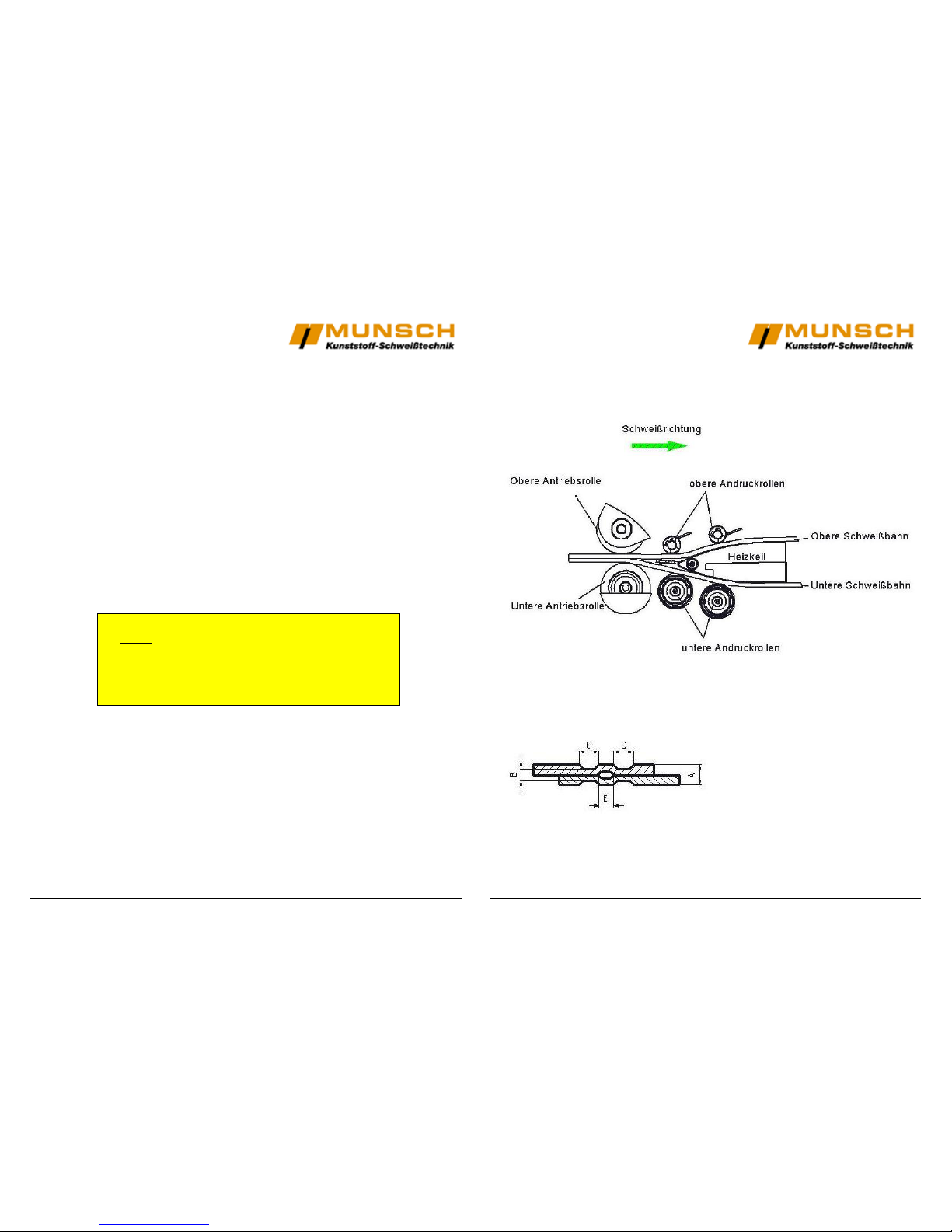
Function
Heating wedge drive system
Overlap weld with air channel
The Wedge It LE produces an
overlap seam with a width of 50 mm
(including air channel) at an overlap
of approx. 130 mm.
A: Sheet thickness
B Thickness of weld seam
C: Part seam 1
D: Part seam 2
E: Air channel

7
Preparation of Unit
The dimension “E“ (wedge position between nip rollers) can be adjusted.
Proceed as follows:
Loosen the two locking screws (A) on the
adjustment disk.
Unlock toggle ( C ) by pulling the T-handle
(B) and rotate toggle (C) counterclockwise until it engages in the bottom
position.
Rotate adjustment disk (D) to adjust the
rear position of the heating wedge
(dimension E). After that, re-tighten the
two locking screws (A).
The angle of inclination of the wedge can
be corrected using the two screws (F).
8
The lower contour rollers (G) can be
adjusted for optimum contact of the sheet
with the wedge. For this purpose, loosen the
hex screws (SW10) on the rear and turn
contour roller (I), which is mounted on
eccentric cams, using an Allan key (SW3).
When the correct clearance between the
contour roller and the heating wedge is
reached, retighten the hex screw.
When operating the unit with power supply from a generator set,
make sure that the generating capacity is sufficient.
 Loading...