


Standard Chemical Pump
Operating manual NPC series
Version BA-2005.07
Print-Nr. 02
VM-Nr. EN
Munsch Chemie-Pumpen GmbH
Im Staudchen
56235 Ransbach-Baumbach
Germany
Phone: +49 (0) 26 23-8 98-90
Fax: +49 (0) 26 23-8 98-95
E-mail: munsch@munsch.de
Internet: http://www.munsch.de
Technical alterations reserved.

Table of contents
Table of contents
1 About this document ............................... 6
1.1 Target groups ................................. 6
1.2 Other applicable documents . .. . .. . .. .. . .. . . 6
1.3 Warning labels and symbols ................ 7
1.4 Technical terms ............................... 7
2 Security ... ........................................... 8
2.1 Intended use ........ .......................... 8
2.2 General safety instructions .................. 8
2.2.1 Product safety ......... ....................... 8
2.2.2 Duties of the operating company . . . .. . .. . .. 9
2.2.3 Duties of the operating personnel . . .. .. . .. . . 9
2.3 Special hazards ............ .................. 9
2.3.1 Explosion hazard area ..................... .. 9
2.3.2 Hazardous pumped media . .. . . .. . .. . .. .. . .. 9
3 Layout and function ................................ 10
3.1 Labels ............ ............................. 10
3.1.1 Type plate ........................... .......... 10
3.1.2 ATEX plate ....................... ............. 10
3.1.3 Pump type code . .. . . . .. . .. . .. .. . .. . .. .. . .. . .. 10
3.2 Layout ............... .......................... 11
3.3 Shaft seals ............... ..................... 11
3.3.1 Mechanical seals ........ ..................... 11
3.4 Auxiliary operating systems ................. 12
3.4.1 Sealing systems ....................... ....... 12
4 Transport, storage and disposal .................. 13
4.1 Transport .................... .................. 13
4.1.1 Unpacking and inspection on delivery .. . .. . 13
4.1.2 Lifting .. ........................................ 13
4.2 Preservation ..................... ............. 14
4.3 Storage ................................ ....... 14
4.4 Disposal ............................. .......... 14
5 Setup and connection ............................ .. 15
5.1 Preparing the setup ................... ....... 15
5.1.1 Checking the ambient conditions . ... .. .. . .. 15
5.1.2 Preparing the setup site ..................... 15
5.1.3 Preparing the foundation and setup
surface ........................................ 15
5.1.4 Installing the heat insulation .. .. . .. .. . ... .. .. 15
5.2 Setup with foundation ........... ............. 16
5.2.1 Setting the pum p aggregate on the
foundation .... ................................ 16
5.2.2 Fastening the pump aggregate .. . .. . ... . .. . 16
5.3 Setup without foundation ..... ............... 17
5.4 Mounting the moto
5.5 Planning the piping .... ....................... 17
5.5.1 Avoid contamination of the piping . . .. . .. .. . . 17
5.5.2 Specifying supports and flange
connections . . .. . ... . .. . .. . .. .. . .. . .. .. . ... . .. . 17
r ..........................
17
5.5.3 Specifying nominal widths ................... 18
5.5.4 Specifying pipe lengths .................. .... 18
5.5.5 Optimizin g cross-section and direction
changes ....................................... 18
5.5.6 Arranging for safety and control devices
(recommended) .............................. 18
5.6 Connecting the pipes ........................ 18
5.6.1 Installing auxiliary pipes ................... .. 18
5.6.2 Installing the suction pipe . . ... . .. . .. . . .. . .. . . 18
5.6.3 Installing the pressure pipe . .. . ... . .. . ... .. .. 18
5.6.4 Inspection for stress-free pipe
connections . . .. . ... . .. . .. . .. .. . .. . .. .. . ... . .. . 19
5.6.5 Inspecting the support foot for
distortion .................... .................. 19
5.7 Electrical connection ......................... 19
5.7.1 Connecting the motor ........................ 19
5.7.2 Checking the direction of rotation .. . .. . . .. . . 19
5.8 Fine alignment of the coupling . ... . .. . .. . . .. 20
5.9 Aligning the motor .......... .................. 20
5.9.1 Aligning the motor using sets of shims . .. . . 20
6Operation ............................................ 21
6.1 Preparations for the initial start-up .. .. . . . .. . 21
6.1.1 Identifying the pump type ....... ............. 21
6.1.2 Lubricating the bearings ..................... 21
6.1.3 Preparing auxiliary operating syste ms (if
available) ........ ............................. 21
6.1.4 Filling and bleeding .......................... 21
6.2 Start up ....................................... 22
6.2.1 Switching on .................................. 22
6.2.2 Switching off .................................. 22
6.3 Shut-down ..................... ............... 23
6.4 Start-up following a shutdown period .. . .. . . 23
6.5 Running the stand-by pump .. ............... 23
7 Maintenance . ........................................ 24
7.1 Inspections . .. . .. .. . .. . .. .. . .. . .. .. . .. . .. .. . .. 24
7.2 Maintenance ........ .......................... 24
7.2.1 Roller bearings with grease lubrication ... . . 24
7.2.2 Roller bearings with oil lubrication . . . .. . .. . . 25
7.2.3 Stationary seal rings .. ....................... 25
7.3 Disassembling . . .. . .. . . .. . .. . .. .. . .. . .. .. . .. . . 25
7.3.1 Returning the pump to the manufac-
turer ................................. .......... 26
7.3.2 Preparations for disassembl ing . . ... . .. . .. . . 26
7.3.3 Loosening connectors (if available) . .. . .. . .. 2 7
7.3.4 Extract ing the volute casing . ... . .. . .. . . .. . .. 27
7.3.5 Disassemblin g the impeller .. .. . ... . .. . .. . . .. 27
7.3.6 Disassemblin g a casing cover with
MUNSCH-REA-C mechanical seal .. . .. .. . . 28
7.3.7 Disassemblin g the atmosphere-side
stationary seal ring ........................... 28
7.3.8 Disassemblin g the bearing bracket . ... . .. . . 29
7.3.9 Disassemblin g the pump shaft . ... . .. . .. . . .. 29
7.4 Assembli
ng ...... .............................
30
2 NPC series BA-2005.07 EN – 02

7.4.1 Preparations for assembling . ... . .. . ... .. .. . 30
7.4.2 Fitting the pump shaft ........ ................ 30
7.4.3 Fitting the bearing bracket . .. . .. . . .. . .. . .. .. . 30
7.4.4 Fitting the casing cover . . .. . ... . .. . .. . .. .. . .. 30
7.4.5 Fitting the pump into the installation . .. . . .. . 30
7.5 Ordering replacement parts ................. 30
8 Disturbance recovery ........... ................... 31
9 Appendix ....... ...................................... 34
9.1 Sectional drawings ........................... 34
9.1.1 Part numbers and designations ............. 34
9.1.2 Overview sect ional drawing . .. . ... . .. . ... .. . 36
9.1.3 Variants .................................. ..... 36
9.2 Technical specifications ................. ..... 40
9.2.1 Ambient conditions ..... ...................... 40
9.2.2 Paramet ers for auxiliary operating
systems ............................ ........... 40
9.2.3 Noise pressure level .. . ... . .. . .. . . .. . .. . .. .. . 40
9.2.4 Tightening torques ........................... 41
9.2.5 Lubricants . . .. . .. .. . ... .. .. . ... .. .. . ... .. .. . ... 42
9.2.6 Detergents .................................... 42
9.2.7 Socket loads according to ISO 5199 .. . . .. . 42
9.3 Replacement parts for 2 years of continuous
operation according to DIN 24296 .. . .. . .. .. 43
Table of contents
EN – 02 BA-2005.07 NPC series 3

Table of contents
List of figures
Fig. 1 Type plate (example) .................... .... 10
Fig. 2 ATEX plate (example) ................. ....... 10
Fig. 3 Pump type code (example) . . .. . ... . .. . .. . .. . 10
Fig. 4 Layout NPC ......................... .......... 11
Fig. 5 Double mechanical seal with quench
(operating principle) ................ .......... 12
Fig. 6 Double mechanical seal with foreign blocking
(operating principle) ................ .......... 12
Fig. 7 Fastening the lifting gear to the pump
aggregate ..................................... 13
Fig. 8 Fastening the lifting gear to the pump . . .. . . 13
Fig. 11 Setup without foundation ..... ............... 17
Fig. 12 Straight pipe lengths upstream and down-
stream of the pump (recommended) . .. . ... 18
Fig. 16 Oil level in sight glass .............. .......... 21
Fig. 17 Loosening the flushing connector or supply
connectors REA-C/D .. . ... . .. . .. . .. .. . ... .. .. 27
Fig. 18 Extracting the volute casing .. . ... . .. . ... . .. . 27
Fig. 19 Disassembling the impeller . . . . .. . .. . .. .. . .. . 27
Fig. 20 Disassembling a casing cover with
MUNSCH-REA-C mechanical seal .. . .. .. . . 28
Fig. 21 Disassembling MUNSCH-REA-D stationary
seal ring ................ ....................... 28
Fig. 22 Disassembling the bearing bracket (grease
lubrication, L16A, L18B, L20A) .. . .. . .. .. . .. . 29
Fig. 23 Disassembling the pump shaft (no lifetime
lubrication) .................................... 29
Fig. 24 Disassembling the pump shaft (with lifetime
lubrication) .................................... 29
Fig. 25 Fitting the casing cover .................. .... 30
Fig. 26 NPC – overview sectional drawing . ... . .. . . 36
Fig. 27 NPC – casing foot .......... .................. 36
Fig. 28 Emptying (optional) .......................... 36
Fig. 29 MUNSCH-REA-C single mechanical
seal ....................... ..................... 37
Fig. 30 MUNSCH-REA-C/D double mechanical
seal ....................... ..................... 37
Fig. 31 Stationary seal ring holder (o
mechanical seal) ............................. 37
Fig. 32 Shutdown/continuous flushing (flushing of
pump interior) ............ ..................... 37
Fig. 33 Single mechanical seal with spring chamber
flushing (supply connectors) . .. . .. . .. .. . .. . . 37
Fig. 34 MUNSCH-REA-C/
tors ............ ................................ 38
Fig. 35 Casing cover (split) ................ .......... 38
D supply connec-
nly for double
Fig. 36 Bearing bracket L16A (grease-lubricated
bearing) ....................................... 38
Fig. 37 Bearing bracket L16A (grease-lubricated
bearing, lifetime lubrication) ................. 38
Fig. 38 Bearing bracket L16A (oil-lubricated
bearing) ....................................... 39
Fig. 39 Bearing bracket L18B (grease-lubricated
bearing) ....................................... 39
Fig. 40 Bearing bracket L18B (oil-lubricated
bearing) ....................................... 39
Fig. 41 Blocking – pressure of sealing medium . . ... 40
Fig. 42 Socket loads at the pump ... . .. . .. . .. .. . .. . . 42
4 NPC series BA-2005.07 EN – 02

List of tables
Tab. 1 Target groups and their duties . .. .. . ... .. .. . 6
Tab. 2 Other applicable documents and their
purpose ....................................... 6
Tab. 3 Warning labels and consequences of
disregarding them .................... ........ 7
Tab. 4 Symbols and their meaning ................. 7
Tab. 5 Technical terms and their meaning .. . .. . .. . 7
Tab. 6 Quenching – variants and characteris-
tics ............... .............................. 12
Tab. 7 Foreign blocking – variants and
characteristics ............................. ... 12
Tab. 8 Action to be taken for pump shutdowns . ... . 23
Tab. 9 Measures depending on pumped medium
behavior ....................... ................ 23
Tab. 10 Actions to be taken after prolon ged shutdow n
periods ....... ................................. 23
Tab. 11 Actions for return ........................ ..... 26
Tab. 12 Fault/number assignment .. . .. . .. .. . .. . .. .. . 31
Tab. 13 Troubleshooting list .......................... 33
Tab. 14 Designations of components listed with part
numbers ................................. ..... 35
Tab. 15 Ambient conditions ................ ........... 40
Tab. 16 Operating parameters for sealing medium in
open flow system ....... ...................... 40
Tab. 17 Noise pressure level . .. . .. .. . ... . .. . .. . .. .. . . 40
Tab. 18 Steel/cast pairing . .. . .. .. . .. . .. .. . .. . . .. . .. . .. 41
Tab. 19 Socket head cap screw 914.1 - steel/steel
pairing ......................................... 41
Tab. 20 Lubricating greases .......................... 42
Tab. 21 Minimum amounts for grease lubrica-
tion ............................................ 42
Tab. 22 Lubricating oils ............................... 42
Tab. 23 Minimum amounts for oil lubrication . . .. . ... 42
Tab. 24 Detergents ... ................................. 42
Tab. 25 Socket loads – forces .. ... .. .. . ... .. .. . ... .. . 42
Tab. 26 Socket loads – torques . . . .. . .. . .. .. . .. . .. .. . 42
Tab. 27 Replacement parts for 2 years' continuous
operation ..... ................................. 43
Table of contents
EN – 02 BA-2005.07 NPC series 5

About this document
1 About this document
This manual
• is part of the pump
• applies to the pump series mentioned above
• describes safe and appropriate operation during all operating phases
1.1 Target groups
Target group Duty
Operating company Keep this manual available at the site of operation of the
installation, including for later use.
Ensure that personnel read and follow the instructions in this
manual and the other applicable documents, especially all safety
information and warnings.
Observe any additional rules and regulation referring to the
installation.
Qualified personnel, fitter Read, observe and follow this manual and the other applicable
documents, especially all safety information and warnings.
Tab. 1 Target groups and their duties
1.2 Other applicable documents
Document Purpose
ATEX additional instructions
Order data sheet Technical specifications, conditions of operation
Setup drawing Setup dimensions, connection dimensions, etc.
Technical description
Sectional drawing Sectional drawing, parts numbers, component designations
Supplier documentation Technical documentation for parts supplied by subcontractors
Replacement parts list
Safety certificate Returning the pump to the manufacturer
Tab. 2 Other applicable documents and their purpose
Operation in explosion hazard areas
Technical specifications, operating limits
Ordering replacement parts
6 NPC series BA-2005.07 EN – 02
1.3 Warning labels and symbols
About this document
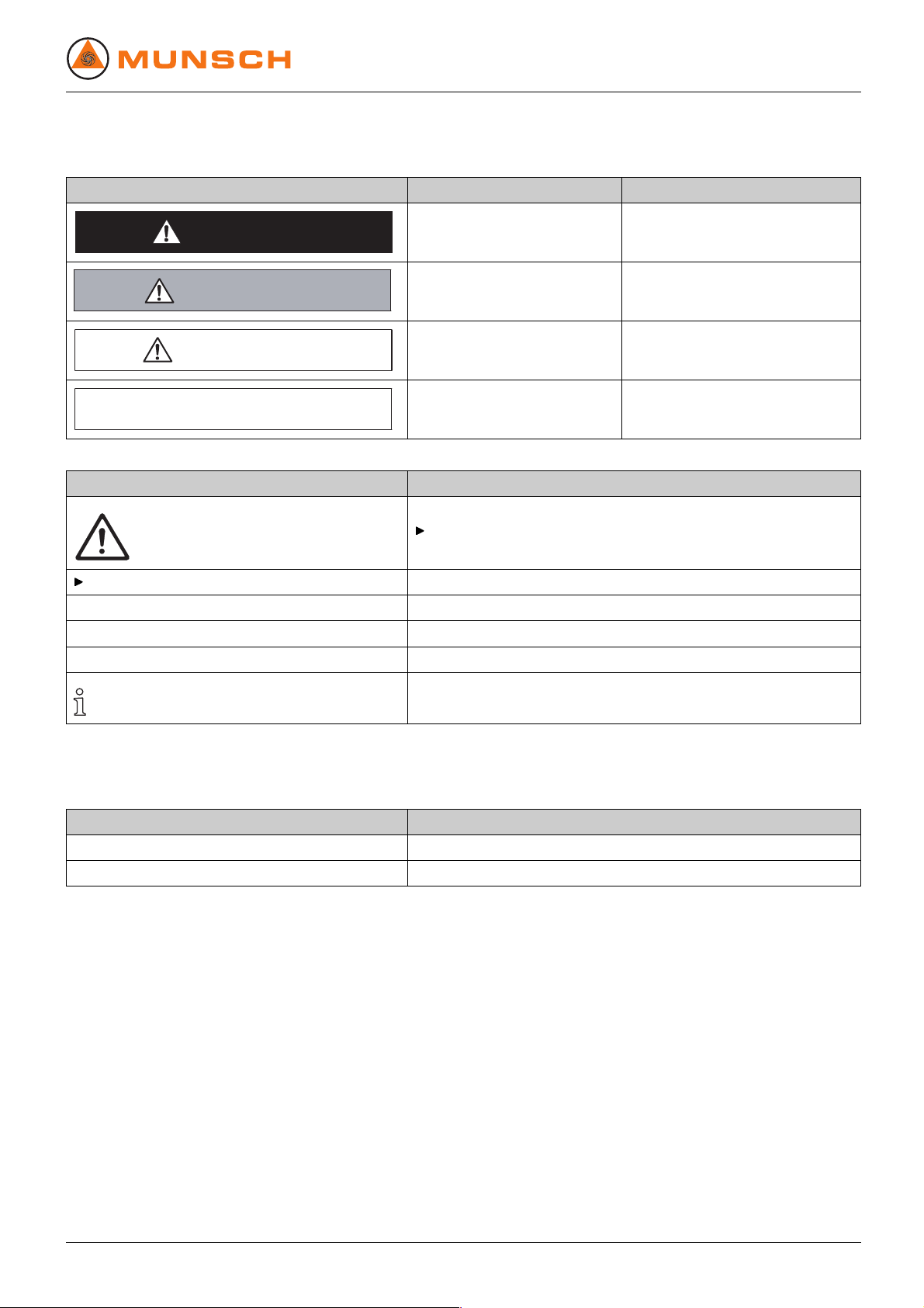
Warning label Risk level
Immediate acute risk Death, grievous bodily harm
DANGER
Potential acute risk Death, grievous bodily harm
WARNING
Potential hazardous situation Minor bodily harm
CAUTION
Potential hazardous situation Material damage
CAUTION
Tab. 3 Warning labels and consequences of disregarding them
Symbol
1. , 2. , ...
→
Meaning
Safety warning sign
Take note of all information highlighted by the safety warning sign
and follow the respective instructions to avoid injury or death.
Safety instruction
Step-by-step safety instructions
Precondition
Cross reference
Information, hint
Consequences of disregard
Tab. 4 Symbols and their meaning
1.4 Technical terms
Ter m Me a n ing
Sealing medium Medium for locking or quenching of shaft seals
Auxiliary operating systems
Tab. 5 Technical terms and their meaning
Systems for operating the pump
EN – 02 BA-2005.07 NPC series 7

Security
2 Security
The manufacturer does not accept any liability for events
resulting from disregard of the entire documentation.
2.1 Intended use
• Only use the pump for pumping the agreed pumped media
(→ Order data sheet).
• Adhere to operating limits and size-dependent minimum
flow rate.
• Avoid dry running:
Initial damage such as destruction of mechanical seal and
plastic parts within only a few seconds.
– Make certain that the pump is never put into operation
and never operated without a pumped medium.
• To avoid cavitation:
– Fully open the suction-side armature and do not use
for adjusting the flow rate.
– Do not open the pressure-side armature beyond the
agreed operating point.
• To avoid overheating:
– Do not operate the pump while the pressure-side arma-
ture is closed.
– Observe the minimum flow rate (→ Order data sheet).
• To avoid damage to the motor:
– Do not open the pressure-side armature beyond the
agreed operating point.
– Observe the allowed number of motor swi tch-ons per
hour (→ Manufacturer's specifications).
• Consult with the manufacturer about any other use of the
pump.
2.2 General safety instructions
Take note of the following instructions before carrying out
any work.
2.2.1 Product safe ty
The pump has been constructed according to up-to-date technology and established technical safety rules. Nevertheless,
operation of the pump can involve risks to life and health of the
user or of third parties, or risks of damaging the pump and other
property.
• Operate the pump only if it is in perfect technical condition,
according to its intended use, in awareness of safety and
risks and in adherence to the instructions in this manual.
• Keep this manual and all other applicable documents complete, legible and accessible to personnel at all times.
• Refrain from any procedures and actions that would
expose personnel or third parties to any risk.
• Should there be any safety-relevant fault, deactivate the
pump immediately and have the fault corrected by appropriate personnel.
• In addition to the entire documentation for the product,
always comply with statutory or other safety and accident-prevention rules and with the applicable standards
and guidelines in the country where the pump is operated.
Prevention of self-evident misuse (examples)
• Observe the operating limits of the pump regarding operating temperature, pressure, flow rate and speed (→ Order
data sheet).
• The power uptake of the pump will increase with increasing
density of the pumped medium. To avoid any overload for
the pump, the coupling and the motor, do not exceed the
allowable density (→ Order data sheet).
A lower density is allowed. Adapt auxiliary system s accordingly.
• Adhere to limits on solids content and grit size when pumping solids-carrying fluids (→ Order data sheet, technical
description).
• When using auxiliary operating systems, en sure that
there is a continuous supply of the appropriate operating
medium.
8 NPC series BA-2005.07 EN – 02

Security
2.2.2 Duties of the operating company
Safety-conscious operating
• Operate the pump only if it is in perfect technical condition,
according to its intended use, in awareness of safety and
risks and in adherence to the instructions in this manual.
• Ensure that the following safety aspects are observed and
monitored:
– adherence to intended use
– statutory or other safety and accident-prevention rules
– safety regulations governing the handling of hazardous
substances
– applicable standards and guidelines in the country
where the pump is operated
• Make protective equipment available.
Qualified personnel
• Make certain that all personnel tasked with work on the
pump have read and understood this manual and all other
applicable documents, especially the safety, maintenance
and repair instructions, before they begin the job.
• Organize responsibilities, who is in charge of any specific
duty and how personnel is supervised.
• Ensure that all work is carried out by specialist technicians
only:
– fitting, repair and maintenance work
– work on the pump electrical system
• Make certain that trainee personnel is supervised by a specialist technician when performing tasks on the pump.
Safety installations
• Provide the following safety installations and verify their
integrity:
– for hot and moving parts: device-side contact protec-
tion on the pump
– in case of potential electrostatic charging: appropriate
grounding
2.2.3 Duties of the operating personnel
• Observe and keep legible all directions given on the pump,
e.g. the arrow indicating the direction of rotation and the
markings for fluid connections.
• Do not remove the contact protection f or hot, cold and moving parts during operation.
• Use protective equipment if necessary.
• Carry out work on the pump only while the pump is not
running.
• Isolate the motor from its supply voltage and keep it locked
in that state while carrying out any fitting or maintenance
work.
• Mount the safety installations on the pump according to
instructions after completion of work on the pump.
2.3 Special hazards
2.3.1 Explosion hazard area
• (→ ATEX additional instructions).
2.3.2 Hazardous pumped media
• Observe the safety regulations for the handling of hazardous substances when working with hazardous pumped
media (e.g. hot, flammable, poison ous or potentially harmful).
• Use protective equipment when carrying out any work on
the pump.
Warranty
• Obtain the manufacturer's approval prior to carrying out
any modification, repair or alterations during the warranty
period.
• Only use original parts or parts that have been approved
by the manufacturer.
EN – 02 BA-2005.07 NPC series 9
Layout and function
3 Layout and function
3.1 Labels
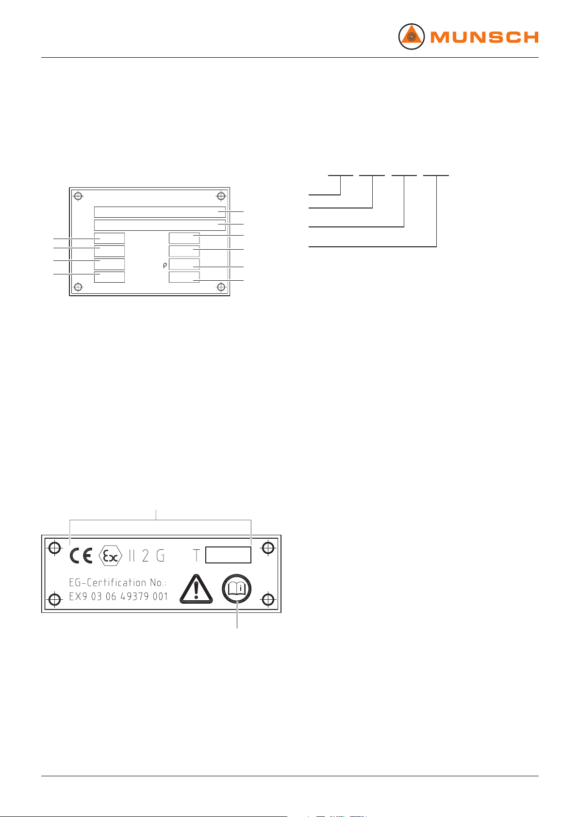
3.1.1 Type plate
MUNSCH Chemie-Pumpen GmbH
Typ
type
W.-Nr.
serial-no.
10
Lfrd.
impeller
9
8
7
Fig. 1 Type plate (example)
1Pumptype
2 Serial number
3 Construction year
4 Total differential head
5 Density
6Torque
7 Speed
8 Power consumption
9Flowrate
10 Impeller di ameter
D-56235 Ransbach-Baumbach
3
Q
P
n
m /h
kW
min
-1
Baujahr
year
3.1.3 Pump type code
NPC
50 - -32 200
1
1
2
3
H
M
m
kg/dm
Nm
4
3
5
6
2
3
4
Fig. 3 Pump type code (example)
1 Pump series
2 Suction flange DN [mm]
3 Pressure flange DN [mm]
4 Impeller nominal diameter [mm]
3.1.2 ATEX plate
1
Fig. 2 ATEX plate (example)
1 Explosion protection mark
2 Reference to ATEX additional instructions
2
10 NPC series BA-2005.07 EN – 02
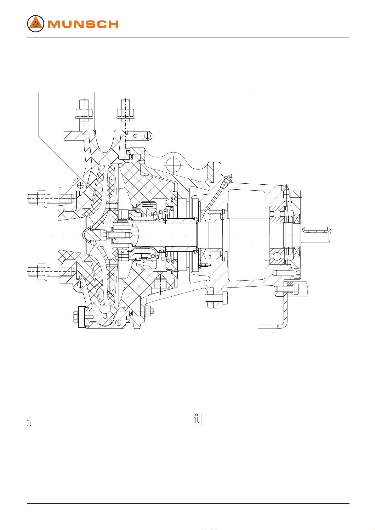
3.2 Layout
Layout and function
1
2 3 4
56
Fig. 4 Layout NPC
1 Impeller
2 Casing armour plating
3.3 Shaft seals
Only one of the following shaft seals can be used.
EN – 02 BA-2005.07 NPC series 11
3 Volute casing
4 Bearing bracket
5 Pump shaft
6 Casing cover
3.3.1 Mechanical seals
Mechanical seals will always show some functional drip
leakage.
• Single mechanical seal
• Double mechanical seal with quench
• Double mechanical seal with foreig
n blocking

Layout and function
3.4 Auxiliary operating systems
3.4.1 Sealing sy stems
Only one of the following sealing systems can be used.
Quenching
1 2
3
Fig. 5 Double mechanical seal with quench
(operating principle)
1 Pumped medium
2 Sealing medium (unpressurized)
3 Double mechanical seal
With quenching, the pressure of the pumped medium exceed s
the pressure of the sealing medium. The sealing friction surfaces of the product-side seal are lubricated by the pumped
medium.
Application examples:
• pumped media that crystallize in air, cau sing long-term
damage to the seal
• prevention of odors
• seal cooling
Varia nt
Open system
Closed system
Tab. 6 Quenching – variants and characteristics
Sealing medium
characteristics
• supplied and drained
continuously
• unpressurized
• circulates in a closed
cycle
• unpressurized
Blocking
1 2
3
Fig. 6 Double mechanical seal with foreign blocking
(operating principle)
1 Pumped medium
2 Sealing medium (pressurized)
3 Double mechanical seal
With foreign blocking, the pressure of the sealing m edium
exceeds the pressure of the pumped medium. The sealing
friction surfaces are lubricated by the sealing medium.
Application examples:
• pumped media that crystallize or carry solids, causing longterm damage to the seal
• toxic pumped media
• pumped media presenting an environmental hazard
Varia nt
Open flow system
Closed flow system
Tab. 7 Foreign blocking – variants and characteristics
Sealing medium
characteristics
• supplied and drained
continuously
• pressurized
• circulates in a closed
cycle
• pressurized
12 NPC series BA-2005.07 EN – 02

4 Transport, storage and disposal
Transport, storage and disposal
4.1 Transport
Weight specifications (→ Individual order documentation).
4.1.1 Unpacking and inspection on delivery
1. Unpack the pump/aggregate on delivery and inspect for
transport damage.
2. Report any transport damage to the manufacturer without
delay.
3. Dispose of packaging material according to local regulations.
4.1.2 Lifting
DANGER
Death or crushing of limbs caused by falling loads!
Use lifting gear appropriate for the total weight to be transported.
Fasten the lifting gear as shown in the illustrations below.
Do not stand under suspended loads.
Fig. 7 Fastening the lifting gear to the pump aggregate
Fig. 8 Fastening the lifting gear to the pump
Lift the pump/aggregate appropriately.
EN – 02 BA-2005.07 NPC series 13
Transport, storage and disposal
4.2 Preservation
No preservation required.
Do not preserve the pump.
4.3 Storage
CAUTION
Material damage due to inappropriate storage!
Store the pump appropriately.
1. Seal all openings with blind flanges, blind plugs or plastic
covers.
2. For mode ls with oil-lubricated bearings and downtimes in
excess of one year:
– Dismount any existing reservoir
– Dismount any existing oil level controller
– Seal the tap hole
– Fill the bearing bracket with oil, up to the brim
– Seal the bleeding hole
3. Make certain that the storage room meets the following
conditions:
–dry
– frost-free
– vibration-free
4. Turn shaft once a month.
5. Make certain that the shaft and the bearing change their
rotational position in the process.
4.4 Disposal
Plastic parts can be contaminated by poisonous or radioactivepumpedmediatosuchanextentthatcleaningwill
be insufficient.
WARNING
Risk of poisoning and environmental damage caused by
pumped medium or oil!
Use protective equipment when carrying out any work on
the pump.
Prior to disposal of the pump:
– Collect pumped medium and oil or grease running out
and dispose of the pumped medium according to local
regulations.
– Neutralize residues of pumped medium in the pump.
Dismount plastic parts and dispose of the parts according
to local regulations.
Dispose of pump according to local regulations.
14 NPC series BA-2005.07 EN – 02

5 Setup and connection
Setup and connection
For pumps in explosion hazard areas (→ ATEX additional
instructions).
CAUTION
Material damage caused by dirt!
Do not remove tra nsport locks until imm ediately before setting up the pump.
Do not remove covers and transport and sealing covers
until immediately before connecting the piping to the pum p.
5.1 Preparing the setup
5.1.1 Checking the ambient conditions
1. Make certain that the required ambient conditions are fulfilled (→ 9.2.1 Ambient conditions, Page 40).
2. For setup sites > 1000 m above sea l evel, consult with the
manufacturer.
5.1.2 Preparing the setup site
Make certain that the setup site meets the following conditions:
– pump is freely accessible from all sides
– sufficient space for installation/removal of the pipes
and for maintenance and repair work, especially for the
removal and installation of the pump and the motor
– pump not exposed to external vibrations (damage to
bearings)
– frost protection
5.1.4 Installing the heat insulation
Only necessary to maintain the temperature of the pumped
medium.
CAUTION
Material damage caused by overheating!
Only install the heat insulation on the volute casing.
Install the heat insulation appropriately.
5.1.3 Preparing the foundation and setup surface
Setup options:
– with concrete foundation
– with steel foundation frame
– without foundation
Make certain that the foundation and setup surface meet
the following conditions:
– level surface
– clean (no oil, dust or other impurities)
– foundation and surface can support the weight of the
pump aggregate and all operating forces
– safe stand of the pump aggregate ensured
– for concrete foundation: Standard concrete of strength
class B 25
EN – 02 BA-2005.07 NPC series 15

Setup and connection
5.2 Setup with foundation
CAUTION
Material damage due to base plate distortion!
Set and fasten the base plate on the foundation as
described in the following.
5.2.1 Setting the pump aggregate on the foundation
✔ Implements, tools and materials:
– foundation bolts (→ Setup drawing)
– steel washers
– mortar grout, non-shrinking
– spirit level
1. Lift the pump aggregate (→ 4.1 Transport, Page 13).
2. Working from below, hang the foundation bolts in the fixation holes of the base plate.
Observe the manufacturer's instruction when using chemical anchors.
3. Set down the pump a ggregate on the foundation. When
doing this, sink the foundation bolts into the prepared
anchoring holes.
5.2.2 Fastening the pump aggregate
Filling out the base plate with mortar grout will improve the
damping behavior.
1. Fill the anchoring holes with mortar grout.
2. Once t he mortar grout has set, screw on the base
plate at three points with the specified tightening torque
(→ 9.2.4 Tightening torques, Page 41).
3. Before tightening the remaining bolts, compensate any
unevenness of the fixation surface, using metal shims next
to each bolt.
4. To inspect the pump aggregate for distortions, using a hair
ruler:
1
32 1 2
Fig. 9 Setup with foundation
4. Use steel washers to align the pum p aggregate to height
and system measures as described in the following:
– Position 1 steel washer (2) each left and right of each
foundation bolt (1).
– If the distance between anchoring holes is > 750 mm,
position additional steel washer (3) centrally at each
side of the base plate.
5. Make certain that the base plate and the steel washers are
in full surface contact.
6. Use machine spirit level to check that the allowable height
deviation (1 mm/m) lengthwise and crosswise is not
exceeded.
7. Repeat procedure until the base plate is correctly aligned.
Fig. 10 Checking for di stortions
– Measure in two planes at an angle of 90° to each other
on the circumference of the coupling.
– Measure the light gap at the outer diameter with hair
ruler (1):
Position the hair ruler across both halves of the coupling.
If there are major deviations, loosen the fixation at the
base plate and correct the distortion by inserting more
shims.
– Fill the base plate with molding material if applicable.
Knock on the base plate to ensure that no cavities are
created in the process.
Couplings with a spacer piece (Dismountable coupling) can
also be inspected with a dial gauge.
16 NPC series BA-2005.07 EN – 02

Setup and connection
5.3 Setup without foundation
✔ Implements, tools and materials:
–Wrench
– Spirit level
1
1
1
2
1
3
4
Fig. 11 Setup without foundation
1. Lift the pump aggregate (→ 4.1.2 Lifting, Page 13).
2. Mount the four leveling feet (1) as shown in the figure.
3. Set down the pump aggregate on the setup surface.
4. Adjust the height of the base plate using leveling feet (1)
as shown above:
– Use wrench to hold the hexagon at leveling foot (4).
– Slacken hexagon nut (2).
– Adjust height by turning hexagon nut (3).
– Tighten hexagon nut (2) (→ 9.2.4 Tightening torques,
Page 41).
– Use machine spirit level to check that the allowable
height deviation (1 mm/m) lengthwise and crosswise
is not exceeded.
– Repeat procedure until the base plate is aligned cor-
rectly.
5.4 Mounting the motor
Only necessary if the pump aggregate is assembled at he
setup site.
CAUTION
Material damage caused by knocks and blows!
Do not cant the coupling halves when pushing on the motor.
Do not knock or hit any component of the pump.
1. Apply a very thin film of molybdenum sulfite (e.g. Molykote)
on the pump and motor shaft ends.
2. Insert keys.
3. Without a mounting device: Remove rubber buffers and
heat coupling halves to approx. 100 °C.
4. Slide on the pump-side and motor-side coupling halves
until the shaft end and the coupling center are flush with
each other. Keep to the specified distance between the
coupling halves (→ Assembly instructions for the coupling).
5. Tighten the threaded pins at both coupling halves.
6. Use suitable m etal shims at the motor to adjust the motor
shaft end to the height of the pump shaft end.
7. Turn in the motor screws, but do not tighten them yet
(→ 5.9 Aligning the motor, Page 20).
5.5 Planning the pipi ng
5.5.1 Avoid contamination of the piping
CAUTION
Material damage due to impurities in the pump!
Make certain that no impurities can get into the pump.
1. Clean all piping components and armatures prior to assembly.
2. Ensure that no flange gaskets are protruding inwards.
3. Remove blind flanges, plugs, protective foils and/or protective paints on flanges.
5.5.2 Specifying supports and flange connections
CAUTION
Material damage due to excessive forces and torque from
piping on the pump!
Do not exceed allowable limits (→ 9.2.7 Socket loads
according to ISO 5199, Page 42).
1. Calculate pipe forces and take into account every possible
operating condition:
– cold/warm
– empty/full
– unpressurized/pressurized
– position shifts of flanges
2. Ensure that pipe supports have permanent low-friction
properties and will not seize up through corrosion.
EN – 02 BA-2005.07 NPC series 17

Setup and connection
5.5.3 Specifying nominal widths
Keep flow resistance in pipes as low as possible.
1. Specify suction pipe nominal width ≥ suction flange nominal
width.
2. Specify pressure pipe nominal width ≥ pressure flange
nominal width.
5.5.4 Specifying pipe lengths
D
C
A
Fig. 12 Straight pipe lengths upstream and downstream
of the pump (recommended)
A>5xDNs
B DNs
C DNd
D>5xDNd
Observe recommended minimum parameters when installing the pump.
Suction side: Shorter pipes are allowable but can restrict
hydraulic performance data.
Pressure side: Shorter pipes are allowable but can lead to
increased operating noise.
5.5.5 Optimizing cross-section an d direction changes
1. Avoid radii of curvature smaller than 1.5 times the nominal
pipe width.
2. Avoid abrupt changes of cross-section along the piping
system.
B
5.5.6 Arranging for safety and control devices (recommended)
Avoiding contamination
1. Integrate filter into the suction pipe.
2. To monitor contamination, mount a differential pressure
gage with a contact manometer.
Avoiding reverse running
1. Install a check valve between the pressure socket and the
gate valve to ensure that the medium will not flow back
whenthepumpisswitchedoff.
2. To allow bleeding, provide a bleeding connection between
the pressure socket and the check valve.
Providing for isolating and shut-off devices for the pipes
For maintenance and repair work.
Provide for shut-off devices in the suction and pressure
pipes.
Allowing the measurement of the operating conditions
1. Provide for manometers for pressure measurements in
suction and pressure pipes.
2. Provide for motor-side torque m easurement.
3. Provide for pump-side temperature measurement.
5.6 Connecting the pipes
5.6.1 Installing auxiliary pipes
Follow manufacturers' specifications of any existing auxiliary operating system.
1. Install auxiliary piping to auxiliary unions, ensuring stress-
free and sealed connections (→ Setup drawing).
2. To avoid air enclosures: run pipes with a continuous slope
up to the pump.
5.6.2 Installing the suction pipe
1. Remove transport and sealing covers at the pump.
2. To avoid air enclosures: run pipes with a continuous slope
up to the pump.
3. Ensure that no gaskets are protruding inwards.
4. For suction operation: Install a foot valve in the suction line
to prevent the pump and suction pipe from running empty
during downtime.
5.6.3 Installing the pressure pipe
1. Remove transport and sealing covers at the pump.
2. Mount the pressure pipe.
3. Ensure that no gaskets are protruding inwards.
18 NPC series BA-2005.07 EN – 02

Setup and connection
5.6.4 Inspection for stress-free pipe connections
✔ Piping complete and cooled down
1. Separate the connecting flanges of the pipes from the
pump.
2. Check that pipes are freely moveable in all directions within
the range of expected expansions:
– nominal width < 150 mm : by hand
– nominal width > 150 mm : with short lever
3. Make certain that the flange surfaces are parallel.
4. Reconnect the connecting flanges of the pipes at the pump.
5.6.5 Inspecting the support foot for distortion
1. Loosen the bolts connecting the support foot to the base
plate.
2. If the support foot moves, compensate distortion:
– lateral shift: by means of slotted holes
– height shift: by means of metal shims
3. Tighten the support foot bolts in t he base plate, making certain that the bearing bracket is not distorted in the process.
5.7 Electrical connection
DANGER
Risk of death through electric shock!
Have all electrical work carried out by qualified electricians
only.
5.7.2 Checking the direction of rotation
DANGER
Risk of death due to rotating parts!
Use protective equipment when carrying out any work on
the pump.
Secure the key against being thrown off during the rotation
direction check.
Keep adequate distance to rotating parts.
CAUTION
Material damage caused by running dry and wrong direction of rotation!
Decouple the motor from the pump.
1. Switch motor on and immediately off again.
2. Check that the direction of rotation of the motor corresponds to the rotational direction arrow on the pump.
3. If the direction of rotation is different: swap two phases.
4. Couple the motor to the pump.
DANGER
Risk of death due to rotating parts!
Isolate the motor from its supply voltage and keep it locked
in that state while carrying out any fitting or maintenance
work.
5.7.1 Connecting the motor
Follow the instructions of the motor manufacturer.
1. Connect the motor according to the connection diagram.
2. Make certain to prevent hazards due to electric energy.
3. Install an EMERGENCY OFF switch.
EN – 02 BA-2005.07 NPC series 19
Setup and connection
5.8 Fine al ignment of the coupling
DANGER
Risk of death due to rotating parts!
Isolate the motor from its supply voltage and keep it locked
in that state while carrying out any fitting or maintenance
work.
CAUTION
Material damage due to incorrect alignment of the coupling!
If there is any height, lateral or angle misalignment, align
the motor exactly with the pump.
For detailed information and special couplings: (→ Manufacturers instructions).
Inspecting the coupling alignment
✔ Implements, tools and materials:
– feeler gage
– hair ruler
– dial gage (can be used for coupling with a spacer piece)
– other suitable tools, e.g. laser alignment instrument
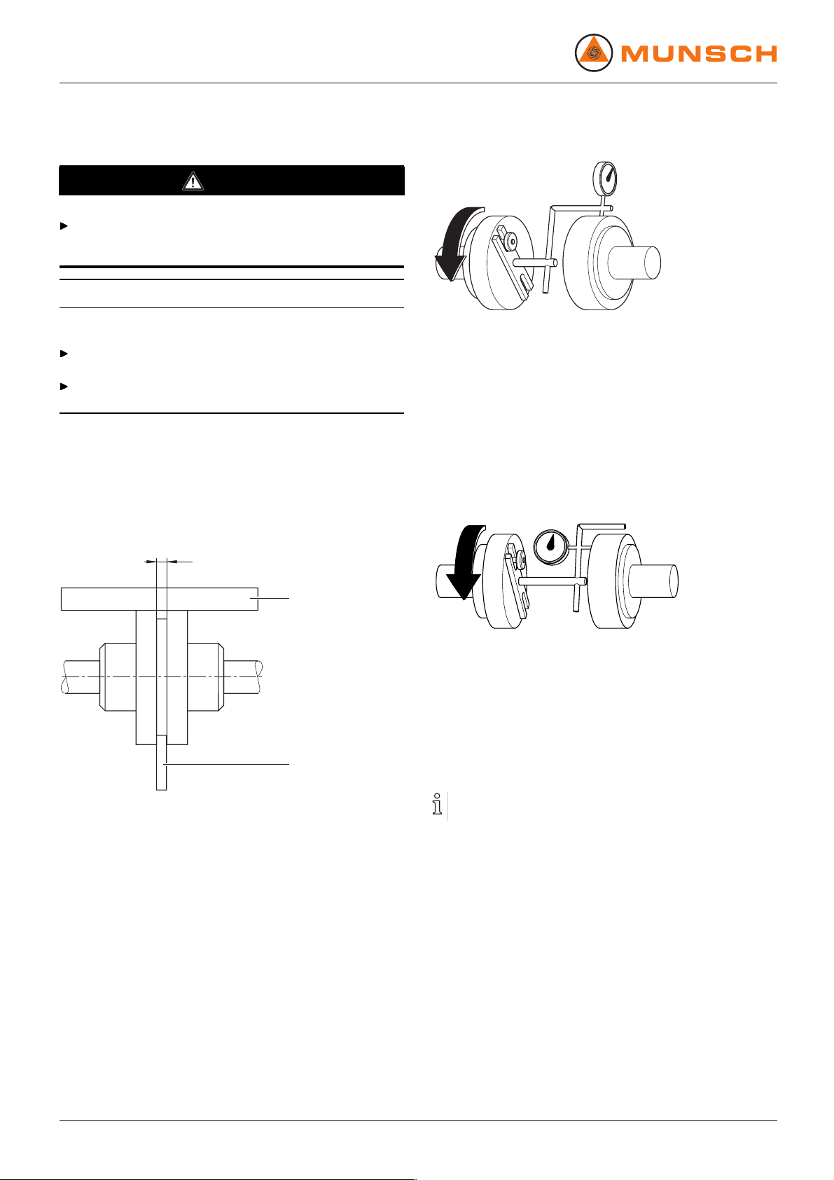
Fig. 14 Inspecting for lateral and height misalignment
4. Inspect for lateral and height misalignments using the dial
gage:
– Carry out the measurement as shown in the figure.
– If there is any lateral or height misalignment, align the
motor (→ 5.9 Aligning the motor, Page 20).
Allowable axial or radial deviation, measured on the
coupling front or coupling circumference, respectively:
<0.05mm
A
1
2
Fig. 13 Inspecting the coupling alignment
1. Measure in two planes at an angle of 90° to each other on
the circumference of the coupling.
2. Measure the light gap to the outer diameter with hair ruler
(1):
– Position the hair ruler across both halves of the cou-
pling.
– If there is a light gap at the outer diameter, align the
motor (→ 5.9 Aligning the motor, Page 20).
3. Measure the gap using feeler gage (2):
– Allowable gap (→ Setup drawing).
– Use the feeler gage for measuring gap width (A)
between the coupling halves.
– If the gap width is outside the allowable range, align
the motor (→ 5.9 Aligning the motor, Page 20).
Fig. 15 Inspecting for angle misalignment
5. Inspect for angle misalignment using the dial gage:
– Carry out the measurement as shown in the figure.
– If there is any angle misalignment: align the motor.
5.9 Aligning the motor
Alignment options:
– using sets of shims
5.9.1 Aligning the motor using sets of shims
1. Align the motor so that the coupling halves are exactly flush
with each other. Underlay with compensation shims where
necessary.
2. Check the alignment.
3. Repeat alignment procedure if there is still a height misalignment.
4. Tighten the motor screws.
20 NPC series BA-2005.07 EN – 02

6 Operation
Operation
For pumps in explosion hazard areas (→ ATEX additional
instructions).
6.1 Preparations for the initial start-up
6.1.1 Identifying the pump type
Identify the pump type (→ Order data sheet).
Pump types vary e.g. with regard to bearing lubrication,
bearing bracket size, type of shaft sealing and auxiliary
operating systems.
6.1.2 Lubricating the bearings
Pumps with grease-lubricated roller bearings are ready for
operation as delivered.
Filling the bearing bracket with lubrication oil
Only for pumps with oil-lubricated roller bearings.
1
6.1.3 Preparing auxiliary operating systems
(if available)
The manufacturer does not accept any liability for damage
arising from the installation or use of a third-party or unapproved auxiliary operating system.
Sealing systems
1. Verify that the sealing medium is suitable for mixing with
the pumped medium.
2. Identify the sealing system (→ Order data sheet)
(→ 3.4.1 Sealing systems, Page 12).
3. Install the sealing system (→ Manufacturer's instructions).
4. Make certain that the parameters required for the installed
sealing system are met (→ 9.2.2 Parameters for auxiliary
operating systems, Page 40).
6.1.4 Filling and bleeding
✔ Auxiliary operating systems are ready for operation
WARNING
Risk of injury and poisoning due to hazardous pumped
media!
Safely collect any emerging pumped medium and dispose
of it in accordance with environmental rules and requirements.
2
Fig. 16 Oil level in sight glass
1 Minimum oil level ⅓ full
2 Maximum oil level ½ full
1. Be certain to use the corre ct type and at least the minimum amount of lubrication oil for filling the bearing bracket
(→ 9.2.5 Lubricants, Page 42).
2. Open the oil filler plug.
3. Fill bearing bracket with lubrication oil until the oil level is
within the specified limits in the sight glass.
4. Screw in the oil filling plug with its gasket.
5. Check the oil level in the sight glass and adjust if necessary.
CAUTION
Material damage caused by dry running!
Make certain that the pump is properly filled.
1. Fill the pump and the suction pipe with pumped medium.
2. Open the suctio n-side armature.
3. Open the pressure-sid e armature.
4. If available: open auxil iary operating systems and check
the flow rate.
5. Verify that all pipe connections are sealed.
EN – 02 BA-2005.07 NPC series 21

Operation
6.2 Start up
6.2.1 Switching on
✔ The pump is correctly set up and connected
✔ The motor is correctly set up and connected
✔ The motor is exactly align ed with the pump
✔ All connections are stress-free and seal ed
✔ Any existing auxiliary operating systems are ready for oper-
ation
✔ All safety installations have been insta lled and tested for
integrity
✔ The pump has been correctly prepared, filled and bled
DANGER
Risk of injury due to running pump!
Do not touch the running pump.
Do not carry out any work on the running pump.
Allow the pump to cool down completely before commenc-
ing any work on it.
DANGER
Risk of injury and poisoning caused by pumped medium
spraying out!
Use protective equipment when carrying out any work on
the pump.
5. For pumps with hot pumped media, make certain that temperature changes do not exceed 50 °C/h.
6. After the first stresses caused by pressure and operating
temperature, check that the pump is not leaking.
7. For hot pumped media, briefly switch off the pump at operating temperature, check the alignment of the coupling and
realign the motor if necessary (→ 5.8 Fine alignment of the
coupling, Page 20).
6.2.2 Switching off
✔ The pressure-side armature is closed (recommended)
WARNING
Risk of injury caused by hot pump parts!
Use protective equipment when carrying out any work on
the pump.
1. Switch off the motor. Maintain the following functions if
applicable:
– for double mechanical seals: block pressure until the
pump is unpressurized
2. Check all connecting bolts and tighten if necessary.
CAUTION
Material damage caused by dry running!
Make certain that the pump is properly filled.
CAUTION
Risk of cavitation when throttling down the suction flow
rate!
Fully open the suction-side armat ure, do not use for adjusting the flow rate.
Do not open the pressure-side armature beyond the operating point.
CAUTION
Material damage caused by overheating!
Do not operate the pump while the pressure-side armature
is closed.
Observe the minimum flow rate (→ Order data sheet).
1. Open the suction- side armature.
2. Close the pressure-side armature.
3. Switch on the motor and check for smooth running.
4. Once the motor has reached its nominal speed, slowly
open the pressure-side armature until the operating point
is reached.
22 NPC series BA-2005.07 EN – 02

Operation
6.3 Shut-down
WARNING
Risk of injury and poisoning due to hazardous pumped
media!
Safely collect any emerging pumped medium and dispose
of it in accordance with environmental rules and requirements.
Carry out the following measures when the pump is shut
down:
Pump is Action
shut down for
a prolonged
period
emptied
disassembled
put into storage Follow storage instructions
Tab. 8 Action to be taken for pump shutdowns
Behavior
of pumped
medium
solids sediment Flush the
solidifies/
freezes,
non-corrosive
solidifies/
freezes,
corrosive
remains liquid,
non-corrosive
remains liquid,
corrosive
Tab. 9 Measures depending on pumped
medium behavior
Carry out measures depending
on the pumped medium
(→ Table 9 Measures
depending on pumped medium
behavior, Page 23).
Close suction-side and
pressure-side armatures.
Isolate the motor from its power
supply and secure against
unauthorized switch-on.
(→ 4.3 Storage, Page 14).
Duration of shutdown (depending
on process)
short long
Flush the
pump.
Heat up or
empty the
pump and
containers.
Heat up or
empty the
pump and
containers.
––
–
pump.
Empty the
pump and
containers.
Empty the
pump and
containers.
Preserve the
pump and
containers.
Empty the
pump and
containers.
Preserve the
pump and
containers.
6.4 Start-up following a shutdown period
1. For shutdowns > 1 year, take the following actions before
restarting the pump:
Shutdown period
>1year For oil-lubricated bearings:
>2years Replace elastomer seals
Tab. 10 Actions to be taken after prolonged
shutdown periods
2. Carry out all steps as for the initial start-up (→ 6.2 Start up,
Page 22).
Action
carry out oil change.
For variants with roller
bearings without lifetime
lubrication: relubricate.
(O-rings, shaft sealing rings).
Replace roller bearings.
6.5 Running the stand-by pump
✔ Thestand-bypumpisfilledandbled
Run the stand-by pump at least once a week.
1. Completely ope n the suction-side armature.
2. Open the pressure-side armature to an extent that the
stand-by pump reaches its operating temperature and is
heated through evenly (→ 6.2.1 Switching on, Page 22).
EN – 02 BA-2005.07 NPC series 23

Maintenance
7 Maintenance
For pumps in explosion hazard areas (→ ATEX additional
instructions).
Trained service technicians are available for fitting and
repair jobs. Present a pumped medium certificate (DIN
safety data sheet or safety certificate) when requesting
service.
7.1 Inspections
The inspection intervals depend on the operational strain
on the pump.
DANGER
Risk of injury due to running pump!
Do not touch the running pump.
Do not carry out any work on the running pump.
WARNING
Risk of injury and poisoning due to hazardous pumped
media!
Use protective equipment when carrying out any work on
the pump.
1. Check at appropriate intervals:
– compliance with minimum flow rate
– roller bearing temperatures < 70 °C
– normal operating conditions unchanged
– top up oil if necessary
– coupling alignment and condition of elastic elements
2. For trouble-free operation, always ensure the following:
– no dry running
– no leaks
– no cavitation
– suction-side gate valves open
– unobstructed and clean filters
– sufficient supply pressure
– no unusual running noises and vibrations
– no excessive leakage at the shaft seal
– proper functioning of auxiliary operating systems
7.2 Maintenance
Service life of the roller bearings for operation within the
allowable operating regime: > 2 years
Intermittent operation, high temperatures, low viscosity and
aggressive ambient and process conditions reduce the service life of roller bearings.
Stationary seal rings are subject to natural wear, which
strongly depends on the actual operating conditions.
Therefore, general statements regarding their service life
cannot be made.
DANGER
Risk of injury due to running pump!
Do not touch the running pump.
Do not carry out any work on the running pump.
Isolate the motor from its supply voltage and keep it locked
in that state while carrying out any fitting or maintenance
work.
DANGER
Risk of death through electric shock!
Have all electrical work carried out by qualified electricians
only.
WARNING
Risk of injury and poisoning due to hazardous or hot
pumped media!
Use protective equipment when carrying out any work on
the pump.
Allow the pump to cool down completely before commencing any work.
Make certain that the pump is unpressurized.
Empty the pump, safely collect the pumped medium and
dispose of the medium in accordance with environmental
rules and requirements.
7.2.1 Roller beari ngs with grease lubrication
1. As a precaution, replace roller bearings with lifetime lubrication every 2 years (recommended).
2. Relubricate roller bearings that can be relubricated:
– after every 3000 hours of operation
– (→ 9.2.5 Lubricants, Page 42).
24 NPC series BA-2005.07 EN – 02

Maintenance
7.2.2 Roller bearings with oil lubrication
1. Carry out lubricating oil change:
– after the first 300 hours of operation
– after every 5000 hours of operation or at least once a
year
2. For o il changes, remove the screwed plug at the bearing
bracket and drain the lubrication oil at operating temperature into a suitable container.
3. Reinsert the screwed plug and top up lubricating oil
(→ 6.1.2 Lubricating the bearings, Page 21).
7.2.3 Stationary seal rings
Mechanical seal will always show some functional dripleakage (→ Manufacturer's instructions).
Double mechanical seal with quench: any drastic rise of the
quench system level indicates a major leak at the productside mechanical seal.
Double mechanical seal ring with foreign blocking: any
drastic pressure drop in the blocking system (loss of
lubricating fluid) indicates a major leak at the product-side
mechanical seal.
If there is a major leak: replace the mechani cal seal with its
auxiliary seals and check the integrity of auxiliary operating
systems.
7.3 Disassembling
DANGER
Risk of injury due to running pump!
Do not touch the running pump.
Do not carry out any work on the running pump.
Isolate the motor from its supply voltage and keep it locked
in that state while carrying out any fitting or maintenance
work.
DANGER
Risk of death through electric shock!
Have all electrical work carried out by qualified electricians
only.
WARNING
Risk of injury and poisoning due to hazardous or h ot
pumped media!
Use protective equipment when carrying out any work on
the pump.
Allow the pump to cool down completely before commencing any work.
Make certain that the pump is unpressurized.
Empty the pump, safely collect the pumped medium and
dispose of the medium in accordance with environmental
rules and requirements.
EN – 02 BA-2005.07 NPC series 25

Maintenance
7.3.1 Returning the pump to the manufacturer
✔ Pump is unpressurized
✔ Pump is completely empty
✔ Electrical connections are isolated and the motor is
secured against switch-on
✔ Pump has cooled down
✔ Coupling shield is dismounted
✔ For couplings with a spacer piece: spacer piece is removed
✔ Auxiliary operating syst ems are shut down, unpressurized
and emptied
✔ Manometer connections, manometer and fixtures are dis-
mounted
1. Always enclose a truthfully completed safety certificate
when returning pumps or components to the manufacturer.
Order a safety certificate from the manufacturer if required.
2. Take necessary measures, depending o n the required
repair work, as listed in the table below for returning the
pump to the manufacturer.
Repair carried out
at customer's
premises
Action for return
Return the defective
component to the
manufacturer.
at manufacturer's
premises
Flush the pump and
decontaminate if hazardous
media were pumped.
Return the complete pump
(not disassembled) to the
manufacturer.
at manufacturer's
premises for
warranty repairs
For hazardous pumped
media only: flush and
decontaminate the pump.
Return the complete pump
(not disassembled) to the
manufacturer.
Tab. 11 Actions for return
7.3.2 Preparations for disassembling
✔ Pump is unpressurized
✔ Pump is completely empty, flushed and decontaminated
✔ Electrical connections are isolated and the motor is
secured against switch-on
✔ Pump has cooled down
✔ Coupling shield is dismounted
✔ For couplings with a spacer piece: spacer piece is removed
✔ Auxiliary operating syst ems are shut down, unpressurized
and emptied
✔ Manometer connections, manometer and fixtures are dis-
mounted
The pumps are constructed in process architecture as standard. The slide-in unit can be dismounted witho ut removing
the volute casing and piping.
If a coupling with a spacer piece is used, the motor can
remain mounted on the base plate.
1. For disassembling take note of the following:
– Precisely mark the assembly orientation and position
of all components before disassembly.
– Dismount components concentrically without canting.
– Disassemble the pump (→ Sectional drawing).
2. Loosen the fixation bolts of support foot 183 and casing
feet 187.
3. Lift the pump out of the installation (→ 4.1.2 Lifting,
Page 13).
26 NPC series BA-2005.07 EN – 02

Maintenance
7.3.3 Loosening connectors (if available)
Flushing connector or supply connectors REA-C/D
710.2/.3
412.70/.8
925
718
412.70/.8
710.1
Fig. 17 Loosening the flushing connector or supply
connectors REA-C/D
1. Loosen lock nut 925.
2. Screw in socket 718 clockwise with a few turns.
3. Loosen and unscrew pipes Skt12 710.1/.2/.3.
4. Unscrew socket 718.
5. Remove O-rings 412.70/.8 from pipes 710.1/.2/.3.
7.3.4 Extracting the volute casing
155+
102
Fig. 18 Extracting the volute casing
1. Loosen the casing nuts.
2. Loosen and extract casing armour plating 155 and volute
casing 102 by screwing in the two ejector screws.
7.3.5 Disassembling the impeller
Connector for spring chamber flushing
Loosen and unscrew fittings 738.
412.74
230
938
412.4
906
Fig. 19 Disassembling the impeller
1. Loosen and remove impeller screw 906 and O-ring 412.4
using circlip pliers.
2. Unscrew socket head ca p screw with SCHN ORR spring
washer 938.
3. Extract impeller 230.
4. Remove O-ring 412.74 from impeller.
EN – 02 BA-2005.07 NPC series 27
Maintenance
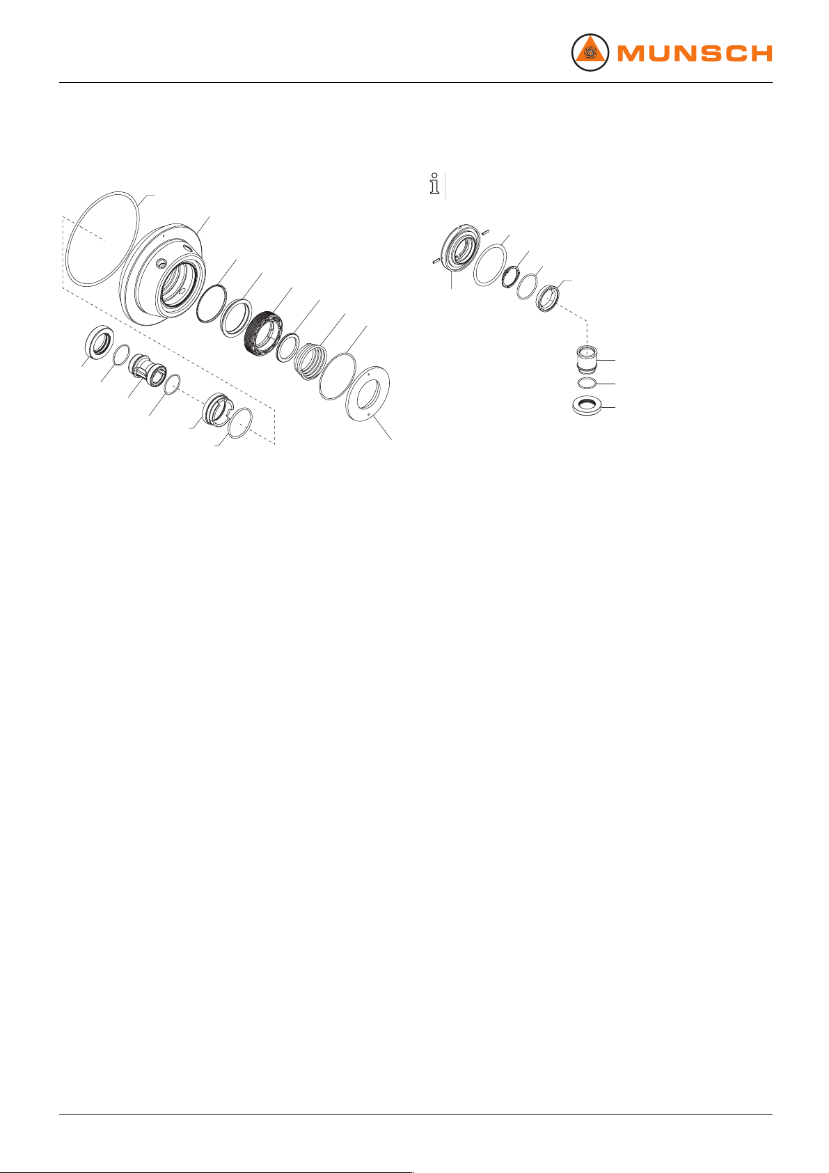
7.3.6 Disassembling a casing cover with
MUNSCH-REA-C mechanical seal
400.10
161
412.3
474.1
473
474.2
477
412.6
472
412.61
523.6
412.5
475
412.2
Fig. 20 Disassembling a casing cover with
MUNSCH-REA-C mechanical seal
1. Extract rotating seal ring 472 with shaft sleeve 523.6 from
pump shaft 211. Free the rotating seal ring from the shaft
sleeve.
2. Remove casing cover 161 and put it down with seal cover
471 facing down.
3. Remove gasket 400.10 from casing cover 161 and replace
gasket if necessary.
4. Extract stationary seal ring 475.
5. Turn the casing cover upside down.
6. Loosen and un screw seal cover 471 using an adjustable
pin wrench.
7. Remove spring 477 and thrust ring 474.2.
8. Unscrew stat ionary seal ring holder 473 using the special
tool.
9. Remove thrust ring 474.1.
10. Remove and replace O-rings 412.61, 412.5, 412.2, 412.6,
412.3.
471
7.3.7 Disassembling the atmosphere-side stationary seal ring
Only for MUNSCH-REA-C/D double mechanical seal.
412.9
477.2
412.45
475.2
473.2
523.5
412.52
472.2
Fig. 21 Disassembling MUNSCH-REA-D station-
ary seal ring
1. Remove rotating seal ring 472.2 and shaft sleeve 523.5.
2. Remove stationary seal ring holder 473.2.
3. Extract stationary seal ring 475.2 from the stationary seal
ring holder.
4. Remove spring 477.2.
5. Remove and replace O-rings 412.52, 412.45, 412.9.
28 NPC series BA-2005.07 EN – 02

Maintenance
7.3.8 Disassembling the beari ng bracket
✔ Intermediate lantern 146 disassembled.
937
360.4
421.1
636.2
636.1
330
412.12
421.2
360
914.3
901.3183
Fig. 22 Disassembling the be aring bracket (grease
lubrication, L16A, L18B, L20A)
1. To dismount support foot 183: Loosen hexagon head bolts
901.3.
2. Unscrew grease nipples 636.1 and 636.2 if applicable.
3. Loosen countersunk screws 937 and remove bearing cover
360.4.
4. Unscrew socket head cap screws 914.3 and extract bearing cover 360.
5. Remove radial shaft seal ring 421.2 and O-ring 412.12 from
bearing cover 360.
6. Remove radial shaft seal rings 421.1 from bearing bracket
330.
7.3.9 Disassembling the pump shaft
With roller bearings without lifetime lubrication
322
940.1
932.1
(322)
932.1
211
940.2
321
923
Fig. 23 Disassembling the pump shaft (no
lifetime lubrication)
1. Press out pump shaft 211 with radial ball bearing 321 from
bearing bracket 330 towards the motor end.
2. Remove bearing nut 923.
3. Extract radial ball bearing 321 and inner ball race (322) of
radial roller bearing 322 from pump shaft 211.
4. Remove circlip 932.1.
5. Press out radial roller bearing 322 from bearing bracket 330
and remove second circlip 932.1.
With lifetime-lubricated roller bearings
321.6
940.1
211
932.1
940.2
321
923
Fig. 24 Disassembling the pump shaft (with
lifetime lubrication)
1. Remove circlip 932.1.
2. Press out pump shaft 211 with radial ball bearings 321 and
321.6 from bearin g bracket 330.
3. Remove bearing nut 923.
4. Extract radial ball bearings 321 and 321.6 from pump shaft
211.
With labyrinth rings
(→ Additional instructions).
EN – 02 BA-2005.07 NPC series 29

Maintenance
7.4 Assembling
7.4.1 Preparations for assembling
1. For assembling take note of the following:
– Replace worn components w ith authentic replacement
parts.
– Replace gaskets, insert new gaskets so that they can-
not rotate.
– Observe specified tightening torque (→ 9.2.4 Tighten-
ing torques, Page 41).
– Refit components concentrically without canting
according to the prepared orientation and position
markings.
2. Clean all components (→ 9.2.6 Detergents, Page 42). Do
not remove the prepared markings.
3. Assemble the pump (→ S ectional drawing).
Assembly is carried out in reverse order of disassembly.
The following sections only describe particular aspects to
be observed when assembling the product.
7.4.2 Fitting the pump shaft
With roller bearings without lifetime lubrication
1. Heat up inner ball race of radial roller bearing 322 and press
it onto pump shaft 211.
2. Heat up radial ball bearing 321 and press it onto pump shaft
211.
3. Cool down radial ball bearing 321 and grease it if it is
grease-lubricated.
4. Screw bearing nut 923 onto pump shaft 211.
5. Screw in threaded pins with 1 drop of LOCTITE 243 in bearing nut 923 and apply color markings to the threaded pins.
6. Insert circlip 932.1 in bearing bracket 330.
7. Press in radial roller bearing 322 and grease it if it is greaselubricated.
8. Insert circlip 932.1.
9. Press pump shaft 211 into bearing bracket 330.
10. For bearing bracket L18B (→ Figure Bearing bracket L18B
(grease-lubricated bearing), Page 39).
With lifetime-lubricated roller bearings
1. Heat up radial ball bearings 321 and 321.6 and press them
onto pump shaft 211.
2. Screw bearing nut 923 onto pump shaft 211.
3. Screw in threaded pins with 1 drop of LOCTITE 243 in bearing nut 923 and apply color markings to the threaded pins.
4. Insert circlip 932.1 in bearing bracket 330.
5. Press pump shaft 211 into bearing bracket 330.
7.4.3 Fitting the bearing bracket
1. Insert radial shaft seal ring 421.2 and O-ring 412.12 into
bearing cover 360.
2. Screw on bearing cover 360 with socket head cap screw
914.3.
3. Insert radial shaft seal ring 421.1 in bearing bracket 330.
4. Screw on bearing cover 360.4 with socket head cap screws
937.
7.4.4 Fitting the casing cover
560
146 161
Fig. 25 Fitting the casing cover
Fit casing cover 161 into intermediate lantern 146.
7.4.5 Fitting the pump into the installation
(→ 5 Setup and connection, Page 15).
7.5 Ordering replacement parts
For trouble-free replacement in case of any fault we recommend keeping a complete slide-in units or replacement
pumps available on site.
The application guidelines according to DIN 24296 recommend provisioning for two years of continuous use
(→ 9.3 Replacement parts for 2 years of continuous operation according to DIN 24296, Page 43).
Have the following information ready to hand for ordering
replacement parts (→ Type plate):
– short designation of the pump
– serial number
– construction year
– part number
– designation
– quantity
30 NPC series BA-2005.07 EN – 02

8 Disturbance recovery
For faults which do not appear in the following table or faults
that cannot be traced back to the suggested causes, please
consult with the manufacturer.
Possible faults are identified by a fault number in the below
table. This number points to the respective cause and remedy
in the troubleshooting list.
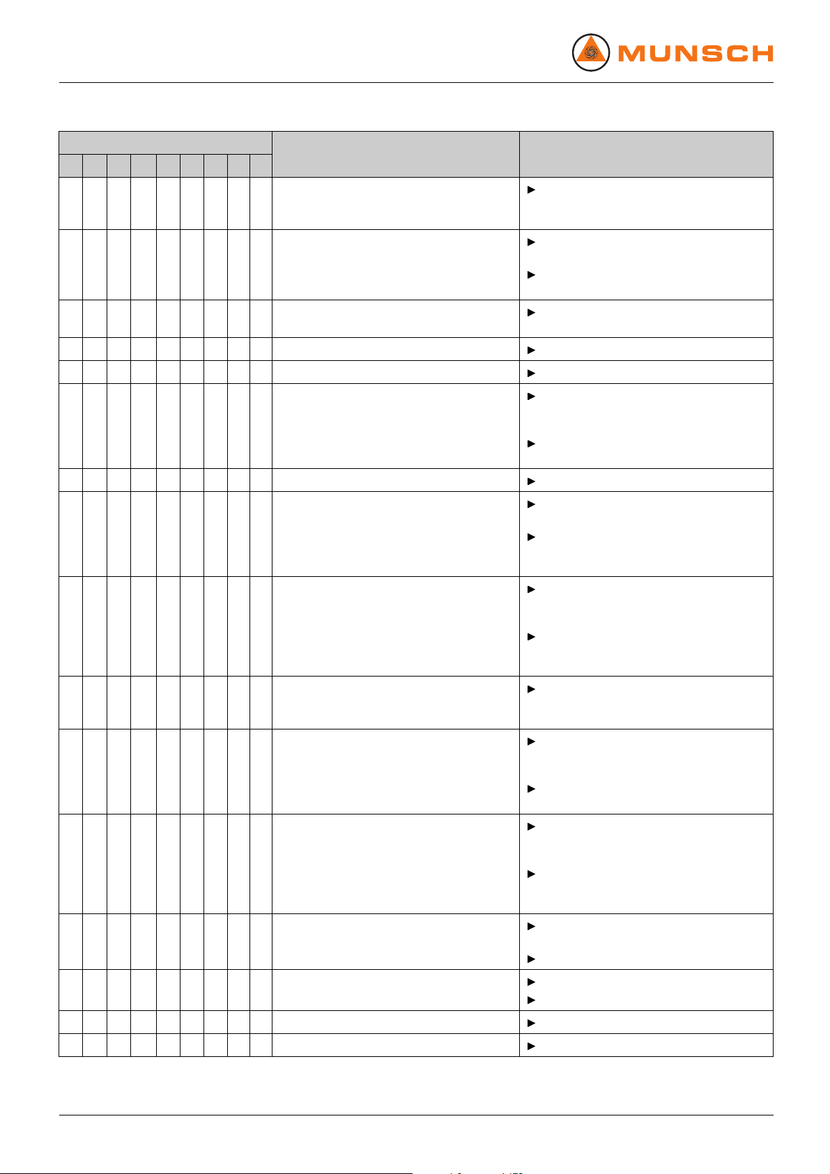
Fault Number
Pump not pumping 1
Pumping rate insufficient
Pumping rate excessive 3
Pumping pressure insufficient
Pumping pressure excessive
Pump running roughly 6
Roller bearing temperatures too high
Pump leaking 8
Motor power uptake excessive 9
Tab. 12 Fault/number assignment
2
4
5
7
Disturbance recovery
Fault number
12 3456
––– –––––
X
–
XX–X
–
X
–
X
X
XX–X
XX–X
–
–
X
–
X
––– –––––
–
X
––––X–––
––––X–––
–
X
–––––
X
–
–
X
–
X
–
–
–
X
7
–––
X
–––
X
–––
X
–––
X
–––
X
–––
X
89
Cause
Supply/suction line and/or pressure line
closed by armature
Supply/suction pipe not fully opened
Supply/suction pipe, pump or suction
screen blocked or encrusted
Supply/suction pipe cross-section too
narrow
Transport and sealing cover still in place Remove transport and sealing cover.
Differential head excessive: NPSH
larger than NPSH
Supply/suction pipe and pump not bled
properly or not filled up completely
Supply/suction line contains air enclosures
Air sucked in
Excessive amount of gas: pump cavitated
Pumped medium temperature too high:
pump cavitated
installation
pump
Remedy
Open the armature.
Open the armature.
Clean supply/suction pipes, pump or
suction screen.
Increase cross-section.
Remove encrustations from suction
pipe.
Open the armature completely.
Disassemble pump and inspect for
dry-running damage.
Increase supply pressure.
Consult with manufacturer.
Fill up pump and/or piping completely
and bleed them.
Mount armature for bleeding.
Correct the piping layout.
Seal the source of malfunction.
Consult with manufacturer.
Increase supply pressure.
Lower the temperature.
Inquire with manufacturer.
EN – 02 BA-2005.07 NPC series 31
Disturbance recovery
Fault number
12 3456
–
–
–
XX
XX–X
XX–X
–
––
–
X
–
X
––
X
––
–
X
XX–X
––––
X
–––––
X
XX
XX
–
–––––
–
X
7
–––
–––
–––
X
XX
––
89
––
––X––X––
––X–
––X–
––X–
XX–X
–
–
X
X
–– –– –
––––
X
XXX–X Motor speed excessively high
XX
–
–
––
–––
X
–––
X
XX–X
–––– ––X–
Cause
X
Viscosity or density of the pumped
medium outside the specification range
for the pump
Geodetic differential head and/or pipe flow
resistance too high
Pressure-side armature not opened
sufficiently
Pressure pipe blocked
Pump running the wrong direction
Motor speed insufficient
Pump components worn
X Pressure-side armature opened too wide
X
Geodetic differential head, pipe flow
resistance and/or other resistance lower
than specified
Viscosity lower than expected
X Impeller diameter too large
Impeller out of balance or clocked
Hydraulic components of the pump dirty,
clotted or encrusted
Roller bearing in bearing bracket defective
X
Roller bearing in motor defective
Remedy
Consult with manufacturer.
Remove sediments in pump and/or
pressure pipe.
Install larger impeller and consult with
manufacturer.
Open the pressure-side armature.
Clean the pressure pipe.
Swap any two phases at the motor.
Compare required motor speed with
specification on pump type plate.
Replace motor if necessary.
Increase motor speed with speed
control if available.
Replace worn pump components.
Throttle down at pressure-side
armature.
Mill down the impeller. Consult with
manufacturer and adjust impeller
diameter.
Throttle down flow rate at pressure-side
armature. Observe the minimum flow
rate limit.
Mill down the impeller. Consult with
manufacturer and adjust impeller
diameter.
Mill down the impeller. Consult with
manufacturer and adjust impeller
diameter.
Compare required motor speed with
specification on pump type plate.
Replace motor if necessary.
Reduce motor speed with speed control
if available.
Throttle down flow rate at pressure-side
armature. Observe the minimum flow
rate limit.
Mill down the impeller. Consult with
manufacturer and adjust impeller
diameter.
Disassemble pump and inspect for
dry-running damage.
Clean the impeller.
Disassemble pump.
Clean the components.
Replace roller bearing.
Replace roller bearing.
32 NPC series BA-2005.07 EN – 02

Disturbance recovery
Fault number
12 3456
7
89
–––– ––X––
–––– –––X–
–––– –––X–
–––– –––X–
–––– –––X–
–– –– –
–– –– –
XXXXPumpdistorted
XX
––
–– –– –X–––
–
–
X
–
X
X
––
Tab. 13 Troubleshooting list
Cause
Lubricant: too much, too little or unsuitable
Connecting screw or bolts not tightened
correctly
Stationary seal ring worn
Casing seal defective
Shaft sleeve is infiltrated
Coupling not properly aligned
Coupling packets worn
X Motor running on 2 phases
Remedy
Reduce, top up or replace lubricant.
Tighten connecting screws and bolts.
Replace stationary seal ring.
Replace casing seal.
Replace shaft sleeve and/or O-rings.
Check pipe connections and pump
fixation.
Check coupling alignment.
Check support foot fixation.
Align coupling.
Replace coupling packets and realign.
Check fuse and replace it if necessary.
Check cable connections and
insulation.
EN – 02 BA-2005.07 NPC series 33

Appendix
9 Appendix
9.1 Sectional drawings
9.1.1 Part numbers a nd designations
Part no. Designation
102 Volute casing
122 Blind cover
132 Intermediate piece
146 Intermediate lantern
155
161
161.2
161.3
167
183
187
211
230 Impeller
321 Radial ball bearing
321.5 Radial ball bearing
321.6 Radial ball bearing
322 Radial roller bearing
330 Bearing bracket
360 Bearing cover
360.4 Bearing cover
400.1
400.10
400.2
400.3
412.10
412.12
412.18
412.2
412.3
412.4
412.45
412.5
412.52
412.6
Casing armour plating
Casing cover
Casing cover
Casing cover
Cover insert
Support foot
Casing foot
Pump shaft
Gasket
Gasket
Gasket
Gasket
O-ring
O-ring
O-ring
O-ring
O-ring
O-ring
O-ring
O-ring
O-ring
O-ring
Part no. Designation
412.61
412.70
412.74
412.76
412.8
412.82
412.84
412.9
421.1
421.2
423.1 Labyrinth ring
423.2 Labyrinth ring
471
472 Rotating seal ring
472.2 Rotating seal ring
473
473.2
474.1 Thrust ring
474.2 Thrust ring
475
475.2
477
477.2
500 Ring
523.5
523.6
554.1 Washer
554.14 Washer
554.15 Washer
554.18 Washer
554.19 Washer
554.20 Washer
554.26 Washer
554.3 Washer
560 Pin
560.2 Pin
560.5 Pin
O-ring
O-ring
O-ring
O-ring
O-ring
O-ring
O-ring
O-ring
Radial shaft seal ring
Radial shaft seal ring
Seal cover
Stationary seal ring holder
Stationary seal ring holder
Stationary seal ring
Stationary seal ring
Spring
Spring
Shaft sleeve
Shaft sleeve
34 NPC series BA-2005.07 EN – 02

Part no. Designation
636.1
636.2
637
642
Grease nipple
Grease nipple
Oil filler plug
Oil level sight glass
710.1 Pipe
710.2 Pipe
710.3 Pipe
718
Socket
738 Fitting
901.1 Hexagon head screw
901.15 Hexagon head screw
901.17 Hexagon head screw
901.3 Hexagon head screw
902.1
902.2
902.3
903
Stud
Stud
Stud
Screwed plug
906 Impeller screw
914.1
914.10
914.18
914.19
914.3
Socket head cap screw
Socket head cap screw
Socket head cap screw
Socket head cap screw
Socket head cap screw
920.2 Nut
920.3 Nut
920.5 Nut
923 Bearing nut
925 Lock nut
932.1
937
938
Circlip
Countersunk screw
SCHNORR spring washer
940.1 Fitting key
940.2 Fitting key
Tab. 14 Designations of components listed with
part numbers
Appendix
EN – 02 BA-2005.07 NPC series 35

Appendix
9.1.2 Overview sectional drawing
230
914.10
940.1
938
914.1
412.4
906
920.3
902.2
155
400.10 330 B
902.1920.2554.14
560.5 560 146102
161 A
554.15
122
901.17
Fig. 26 NPC – overview sectional drawing
554.20
554.19
901.15
187
Fig. 27 NPC – casing foot
902.3554.18 920.5
9.1.3 Variants
167412.18
Fig. 28 Emptying (optional)
36 NPC series BA-2005.07 EN – 02

Appendix
161
412.3
474.2
472
412.61
523.6
412.74
475
412.2
474.1
Fig. 29 MUNSCH-REA-C single mechanical seal
161
477
412.2
412.74
412.61
412.6
471
477
423
211
412.76
523.5
412.5
473
560.2
473.2
412.45
475.2
477.2
718
710.3
925
412.8
Fig. 32 Shutdown/continu ous flushing (flushing
of pump interior)
738
412.10
523.6
412.5
475
472
474.2
474.1
412.3
473
Fig. 30 MUNSCH-REA-C/D double mechanical seal
473.2
560.2
Fig. 31 Stationary seal ring holder (only for double
mechanical seal)
412.76
211
523.5
412.52
472.2
412.9
471
412.6
412.10
738
Fig. 33 Single mechanical seal with spring chamber
flushing (supply connectors)
EN – 02 BA-2005.07 NPC series 37

Appendix
718
710.2
925
412.70
412.70
925
710.1
718
Fig. 34 MUNSCH-REA-C/D supply connectors
161.2
161.3
554.26
914.18
412.84
421.1 322 932.1 636.2 330
937
923
360.4
Fig. 36 Bearing bracket L16A (grease-lubricated bearing)
554.1 901.1
183
554.3
412.12
421.1 932.1 321.6 330 321 923 412.12 211
940.2 211321 636.1 421.2
914.3 360901.3
940.2
Fig. 35 Casing cover (split)
SteelPFA
SteelPVDF
Fig. 37 Bearing bracket L16A (grease-lubricated
bearing, lifetime lubrication)
38 NPC series BA-2005.07 EN – 02
901.3
914.3360.4 937 183554.1 901.1 554.3
421.2360

Appendix
400.1
400.2
637932.1
330
183
903901.1
412.12
421.2321 211
923
554.3
901.3
940.2
914.3
421.1
322
642
554.1
400.3
Fig. 38 Bearing bracket L16A (oil-lubricated bearing)
321.5*
412.12330
923
932.1
637
400.1
322
914.19 940.2360
421.2
360
636.2
932.1
330
901.1132
321.5*
554.3
636.1
901.3554.1
412.12
421.2
360
914.3183
360.4
322
914.19
421.1
937
Fig. 40 Bearing bracket L18B (oil-lubricated bearing)
* O-arrangement
940.2
211923
132
554.1
901.1
400.2
903
642
400.3 554.3
421.1
Fig. 39 Bearing bracket L18B (grease-lubricated bearing)
* O-arrangement
EN – 02 BA-2005.07 NPC series 39
901.3183
211
914.3

Appendix
9.2 Technical specifications
Further technical specifications (→ Order data sheet).
9.2.1 Ambient conditions
Consult with the manufacturer about an operation under
other ambient conditions.
Tem p e rature [°C]
–20 to +40 ≤ 85 ≤ 100 ≤ 1000
Tab. 15 Ambient conditions
9.2.2 Parameters for auxiliary operating systems
Sealing medium in open flow system
Sealing medium
for
Quenching
Blocking 30
Tab. 16 Operating parameters for sealing medium
y
10
99
8
7
6
5
4
3
2
Relative humidity [%]
long-term short-term
Volume flow [l/h]
30 unpressurized
in open flow system
Setup level
above sea
level [m]
Pressure
(→ Diagram
below).
9.2.3 Noise pressure level
Measuring conditions:
• Distancetopump:1m
• Operation: cavitation-free
• Motor: IEC standard motor
• Tolerance ±3 dB
Lower-noise motors are available if the noise expectation figures exceed the allowed limits.
Motor nominal
power PM [kW]
1.5 58 58.5 63 64
2.2 60 60.5 66 67
3.0 62 62.5 68 69
4.0 63 63.5 69 70
5.5
7.5
11.0 68 68.5 74
15.0 69 69.5
18.5 70 70.5 76
22.0 71 71.5
30.0 72 72.5 78 79
37.0 73 73.5 79 80
45.0 74 74.5 80 81
55.0
75.0 76 76.5 81 82
90.0 76 76.5 82 83
110.0
132.0 78 78.5 83 84
160.0 79 79.5 84 85
200.0 80 80.5 85 86
Tab. 17 Noise pressure level
Noise pressure level [dB] for pump
with motor at speed [min
1450 1750 2900 3500
65 65.5 71 72
66 66.5 72 73
75 75.5
77 77.5
-1
]
75
75
77
80 81
82 83
76
77
78
1
0
12345678910111213141516
Fig. 41 Blocking – pressure of sealing medium
x Pressure at pressure socket [bar]
y Required pressure for blocking [bar]
40 NPC series BA-2005.07 EN – 02
x

9.2.4 Tightening torques
Tighten bolts diagonally using a torque wrench. The following figures apply to new bolts and nuts.
Thread gage Tightening torque [Nm]
M8 25
M10 35
M12 50
M16 80
Tab. 18 Steel/cast pairing
Thread gage Tightening torque [Nm]
M10 45
Tab. 19 Socket head cap screw 914.1 - steel/steel pairing
Screw down hand-tight for plastic/plastic pairings, e.g.
impeller screw 906.
Appendix
EN – 02 BA-2005.07 NPC series 41

Appendix
9.2.5 Lubricants
Manufacturer
Designation
SKF LGMT3
ARAL HL3
ESSO BEACON 3
MOBIL-OIL MOBILUX 3
SHELL ALVANIA GREASE 3
Tab. 20 Lubricating greases
Bearing
bracket
Bearing
types
Position
(→ Figure
NPC – overview
Lubricant
amount per
lubrication
point [g]
sectional
drawing,
Page 36).
L16A
1 x NU2209 A 10
1 x 6309 B 13
B13
L18B
1xQJ309
1 x NU2210 A 11
1 x 6311 B 18
2x7311
B36
BECBP
Tab. 21 Minimum amounts for grease lubrication
Manufacturer
BP
DEA
Designation
ENERGOL GR-XP 68
FALCON CLP68
ESSO SPARTAN EP68
MOBIL GEAR 626
SHELL OMALA 68
Tab. 22 Lubricating oils
Bearing bracket
Oil volume [l]
L16A 0.35
L18B 1.0
Tab. 23 Minimum amounts for oil lubrication
9.2.6 Detergents
Application area Detergent
Foodstuffs and drinking
water sector
e.g. spirit, Ritzol 155,
strong alkaline soap suds,
steam blast (for individual
components only)
Other
Benzine, wax solvents,
diesel, paraffin, alkaline
detergents
Tab. 24 Detergents
9.2.7 Socket l oads according to ISO 5199
F
z
M
Z
z
X
M
F
x
x
1
M
y
Y
F
y
Fig. 42 Socket loads at the pump
1 Pressure socket
diameter
DN [mm]
Fx [N] Fz [N]Nominal
Pull Push
Fy
[N]
∑F
Pull Push
25 600 300 500 700 350 1100
32 800 400 700 900 450 1500
40 1100 550 900 1200 600 2000
50 1500 750 1300 1600 800 2500
65 1900 950 1600 2000 1000 3500
80 2400 1200 2100 2600 1300 4500
Tab. 25 Socket loads – forces
Nominal diameter DN
[mm]
Mx
[Nm]My[Nm]Mz[Nm]
∑M
[Nm]
25 900 600 800 1550
32 1200 800 700 1700
40 1300 900 1000 1850
50 1400 1000 1100 2000
65 1500 1100 1200 2150
80 1600 1200 1300 2300
Tab. 26 Socket loads – torques
[N]
42 NPC series BA-2005.07 EN – 02

9.3 Replacement parts for 2 years of
continuous operation according
to DIN 24296
Appendix
Part no. Part designation
1234
230Impeller 1111222
211
523.5
523.6Shaftsleeve 111222325%
867
–
Roller bearing with lifetime lubrication
321Radialballbearing 1112223
321.6Radialballbearing 1112223
421.1
421.2
423
Roller bearing without lifetime lubrication
321Radialballbearing 1112223
322Radialrollerbearing1112223
421.1
421.2
423
Seal for volute casing
412.1
OR
400.10
Tab. 27 Replacement parts for 2 years' continuous operation
1) only for pump with lifetime-lubricated roller bearings
2) only for REA-C
3) only for pump with roller bearings without lifetime lubrication
Pump shaft
Shaft sleeve
Coupling buffer
Repair set stationary seal
ring unit
Radial shaft seal ring
Radial shaft seal ring
Axial shaft seal ring
Radial shaft seal ring
Radial shaft seal ring
Axial shaft seal ring
O-ring
Gasket
2)
2)
1111222
1112223
1112234
111222325%
1)
1112223
1112223
1112223
3)
1112223
1112223
1112223
1234
1234
Number of identical pumps (including stand-by pumps)
5
Set/Quantity of spare parts
5
5
6and7 8and9
100 % 100 % 100 %
100 % 100 % 100 %
10 or
more
20 %
20 %
25 %
30 %
25 %
25 %
25 %
25 %
25 %
25 %
25 %
25 %
25 %
25 %
EN – 02 BA-2005.07 NPC series 43

 Loading...