


355x368x130mm
3.5 kgs
225 - 300pcs
70-120PSI (4.9-8.3bar)
1/4’’ N.P.T.
45-90mm
MI CN-90mm
Thank you very much for purchasing our MI CN-90mm Pneumatic Coilnailer
COILNAILER
MI CN-90mm

- 2 -
IMPORTANT SAFETY INSTRUCTIONS
WARNING: When using pne umatic to ols, bas ic safety pre cautions Should al ways
be followed to reduce the risk of personal injury Including the following :
READ AND FOLLOW ALL INSTRUCTIONS.
There are certain applications for which this tool was designed. we strongly
recommends that this tool NOT be modified and /or used for any application other
than for which it was designed. If you have any questions relative to its application,
please contact with your seller.
1. KEEP WORKING AREA CLEAN.
Cluttered areas invite injuries.
2. DON'T ALLOW CHILDREN AT THE
WORKING AREA.
Don't let them handle the
tool.
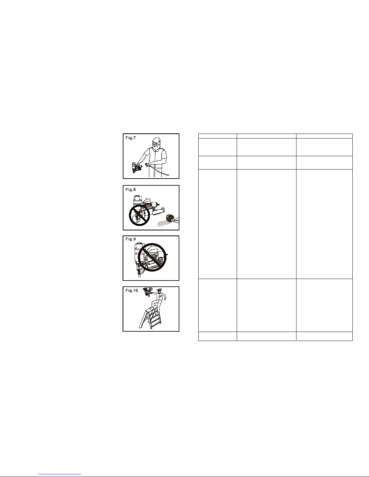
3. USE SAFETY GLASSES.
To prevent eye
injuries, the tool operator and all persons in the
working area must wear safety glasses with
permanently attached, rigid, plastic side shields.
These safety glasses must conform to ANSI Z87.1
requirements (approved glasses have “Z87” printed
or stamped on them).
4 . USE EAR PROTECTION.
The working area
may be exposed to high noise levels that can lead to
hearing damage.
5. DRESS SAFELY.
Protective gloves and nonskid
footwear or safety shoes are recommended when
working with and operating this tool. Don't wear
loose clothing or jewelry. They can get caught in
moving parts. Also, wear a protective hair covering
to prevent long hair from getting caught in the tool.
6. ONLY USE CLEAN, DRY AND
REGULATED
compressed air at 70 to 120 PSI (5
to 8.3 BAR).
PARTS LIST
1 HCN086
Screw
52 HCN135
Washer
2 HCN087
Bushin
g
53 HCN136
Safe Sleeve
3 HCN088
Exhaust Cover
54 HCN137
O-rin
g
6.4x1.8
4 HCN089
Seal
55 HCN138
Washer
5 HCN090
Muffler
56 HCN139
O-rin
g
20.3x2.5
6 HCN001
Screw
57 HCN140
O-rin
g
20.3x1.5
7 HCN091
S
p
ring Washer 6
58 HCN141
Valve Guide
8 HCN092
C
y
linder C a
p
59 HCN041
O-rin
g
9.5x1.9
9 HCN093
Gaske
t
60 HCN142
O-rin
g
10.3x1.9
10 HCN094
S
p
rin
g
61 HCN143
Trigg
er Valve Seat
11 HCN095
Valve Sea
t
62 HCN044
O-rin
g
12.8x1.9
12 HCN096
O-rin
g
48.8x2.5
63 HCN144
Sprin
g
13 HCN097
Valve
64 HCN145
O-rin
g
5.5x1.5
14 HCN098
O-rin
g
67x3
65 HCN146
Trigg
er Valve Stem
15 HCN099
Collar
66 HCN147
Tirgg
er Valve Guide
16 HCN100
C
y
linder Seal
67 HCN148
Spring Pin 3x26
17 HCN101
O-rin
g
57.46x3.53
68 HCN149
Trigg
er Sprin
g
18 HCN102
Piston Assembl
y
69 HCN150
Rotatin
g
Shaft Bushin
g
19 HCN103
C
y
linder
70 HCN151
Locking Washer 3
20 HCN083
O-rin
g
65.4x2.5
71 HCN152
Trigg
er Assembl
y
21 HCN104
Restrictive Plate
72 HCN153
Steel Ball
22 HCN105
O-rin
g
101.91x3.53
73 HCN154
Sprin
g
23 HCN106
Bum
p
er A
74 HCN155
Rotating Shaft Pin
24 HCN107
Bum
p
er B
75 HCN156
Locking Washer 28
25 HCN108
Bod
y
76 HCN157
Cover
26 HCN109
O-rin
g
62.3x1.8
77 HCN158
Piston Bumper
27 HCN110
Nut
78 HCN159
S
p
rin
g
28 HCN111
Washer
79 HCN160
O-rin
g
24.3x2.8
29 HCN112
O-rin
g
8.3x1.8
80 HCN161
Spring Pin 4x12
30 HCN113
Protector
81 HCN162
Piston
31 HCN114
S
p
ring Washer
82 HCN163
O-ring 12.3x1.9
32 HCN115
Screw
83 HCN164
Feed Hook Sea
t
33 HCN116
Nose
84 HCN165
Feed Hook Pin
34 HCN117
Washer
85 HCN166
S
p
rin
g
35 HCN118
Pin
86 HCN167
Feed Hook
36 HCN119
Handwheel Assembl
y
87 HCN168
Screw
37 HCN120
S
p
rin
g
88 HCN169
Pin
38 HCN121
Feed Hook Pin
89 HCN170
Lower Nail Housin
g
39 HCN122
Sto
pp
ed Hook
90 HCN171
Nut
40 HCN123
S
p
rin
g
91 HCN172
Ad
j
usting Stem
41 HCN124
Latch
92 HCN173
S
p
ring Pin 2.5x17
42 HCN125
Safe Guide
93 HCN174
Ad
j
uster Plate
43 HCN126
S
p
ring Pin 3x28
94 HCN175
Sprin
g
44 HCN127
S
p
rin
g
95 HCN176
Ad
j
uster Nu
t
45 HCN128
Screw
96 HCN177
U
pp
er Nail Houshin
g
46 HCN129
Safe Bra c k et
97 HCN178
Washer
47 HCN130
Screw
98 HCN179
Screw
48 HCN131
S
p
rin
g
99 HCN180
Soft Gri
p
Sleeve
49 HCN132
Ad
j
usting Button
100 HCN181
End C a
p
50 HCN133
Ad
j
usting Stem
101HCN085Air Plu
g
51 HCN134
Bracke
t

- 3 -
EXPLODED VIEW DRA WING
7. NEVER USE OXYGEN, CARBON
DIOXIDE, combustible gases or any other
bottled gas as a power source for this tool.
8. DO NOT CONNECT TOOL to pressure
that potentially exceeds 120 PSI (8.3 BAR).
9. ONLY USE AIR HOSE THAT IS
RATED for 150% of the maximum system
pressure. Please try to usea 3/8” ID hose con
nect in nailer with compressor.
10.DON'T OPERATE TO NEAR ANY
COMBUSTIBLE, or any other explosive
material. Don't operate the tool where it is
easy producing corrosion, rust or in a having
heavy powder environment.
11 DISONNECT TOOL FROM AIR
SUPLY HOSE before doing tool
maintenance , clearing a jammed fastener,
leaving work area, moving tool to another
location, or handing the tool to another
person..
12. ONLY DISCONNECT THE QUICK
CONNECTOR with the connector of the
body tail portion air inlet, no compressed
air can be guaranteed when disconnecting. If
operation is not correct, the tool can Remain
charged with air after being disconnected and
still be able to drive a fastener, causing
personal injury.
13. REPLACE PARTS AND ACCESSORIES. Only allow use same repla cement parts
while servicing. Approved accessories and replacement parts are available.
- 4 -
14. BEFORE USING TOOL, carefully check if
there is any part damaged to obtain ideal results. Do
not use the tool if the tool has any air leaks,
uncompleted, damaged parts and needs repairing.
15. NEVER USE TOOL if safety, trigger or spring is
inoperable, missing or damaged. Do not alter or
remove safety, trigger or springs Make daily
inspections for free movement of trigger and safety
mechanism.
16.ONLY USE PARTS AND FASTENERS
recommended by us.
17. CONNECT TOOL TO AIR SUPPLY BEFORE
loading fasteners to prevent fastener from being fired
during connection. The tool driving mechanism
may cycle when tool is connected to the air supply.
When not in use remove all fasteners from the nail
housing.
18. ALWAYS ASSUME THE TOOL CONTAINS
FASTENERS. Keep the tool pointed away from
yourself and others at all times. No horseplay. Respect
the tool as a working implement.
19. DO NOT LOAD FASTENERS with trigger or
safety depressed to prevent unintentional firing of a
fastener.
20. REMOVE FINGER FROM TRIGGER when
not driving fasteners. Never carry tool with finger on
trigger: tool will fire a fastener if safety is bumped
while trigger is depressed.
21. DON'T OVER REACH. Keep proper footing
and balance at all times when using or handling the
tool.
22. FIRE FASTENERS INTO WORK SURFACE
ONLY: NEVER into materials too hard to penetrate.
PROBLEM CAUSE SOLUTION
Failure to start tool. 1. Tool dry, lacks lubrication.
2. The spring in the cylinder cap is
damaged.
3. Valve sticks with cylinder cap.
1. Use pneumatic tool oil
2.Replace the spring in the
cylinder cap.
3.Disassemble/check/lubricate
Blade driving fasteners
too deeply
1. Safe bracket poison is not correct.
2. Air pressure is too high.
1. Rotate knob of the adjuster to
move safe bracket down.
2. Decrease air pressure.
Skipping
fasteners/ feeding
intermittently
1. Having foreign matters between the
small piston and small cylinder.
2. O-ring on the small piston is worn
and damaged.
3. Tool dry and lacks lubrication.
4. The spring on the small piston is
damaged.
5. Air pressure is lower.
6. Connecting screw of nose and body
is loose.
7. Stopped hook can't stop the
fasteners.
8. Bent fasteners.
9. Wrong size fasteners.
10. Gasket is damaged.
11.Dry small piston
12. Small piston bumper is worn and
damaged.
13. Feed hook is binding.
14. Nail length is not correct with
loading space of nail housing.
15. Weld wires in nail coilare broken.
1. Disassemble/ clean/lubricate.
2.Check/replaceO-ring/ lubricate
3. Use pneumatic ic tool oil.
4. Replace small piston the spring.
5. Increase the air pressure, but don't
exceed 120 PSI (8.3 bar).
6. Tighten al l screws.
7.Replace taper spring of the
stopped hook.
8. Use recommended fasteners.
9.Use recommended fasteners
10. Replace gasket/t tighten screw.
11. Open nai l housing, place several
drops of pneumatic tool oil into end
cover hole of the small piston.
12.Replace bumper and lubricate
small piston.
13. Clean feed hook and torsion
spring.
14.Adjust adjusting nut at the nail
housing tail portion according to the
recommended nail length to make
arrow on the nail housing tail point
to correct direction.
15. Stop using.
Runs slowly or has
power loss
1. Tool dry, lacks lubricate ion
2. The spring in the cylinder cap is
damaged.
3. Having foreign matters between
piston assembly and cylinder.
4. Have not assembled the cylinder to
home posit ion.
5. O-ring on the valve is dry after
disassembly.
6. Air pressure is too low.
7.Driver is worn (sort)
8. Inner diameter of hose is small.
1. Use pneumatic tool oil.
2. Replace the spring in the cylinder
cap.
3. Disassemble/clean/lubricate.
4. Reassemble after disassembling.
5.Reassemble after lubricating
6. Increase the air pressure, but don't
exceed 120 PSI (8.3 bar).
7. Replace piston assembly.
8. Use bigger inner diameter of the
hose.
Fasteners are jammed 1. Fasteners are wrong size.
2. Weld wires in nail coil are broken.
1. Use recommended fasteners.
2. Stop using.

- 5 -
Keep all screws tight. Loose screws can cause personal injury or damage tool.
Check if there are worn and damaged parts. If any, please replace immediately.
If tool is used without an in-line oiler: place 5 or 6 drops of air tool oil into the
air inlet of the tool at the beginning of each workday.
SERVICE AND REPAIR
All quality tools eventually require servicing of replacement parts due to wear
from normal use. Some user serviceable components are described in the
TROUBLESHOOTING Sect ion. All repairs made by local agencies are fully
guaranteed against defective material and workmanship. We cannot guarantee
repairs made or attempted by anyone other than these agencies.
Should you have any questions about your tool , please contact with seller at any
time. In any communications, please give all information shown on the
nameplate of your tool (model number, type, serial number, etc.)
TROUBLESHOOTING
CAUTION: Disconnect tool from air supply before perform i ng
any service procedure.
PROBLEM CAUSE SOLUTION
Air leaking at trigger
area
1. O-ring in trigger valve stem is worn
and damaged.
2. O-ring in trigger valve head is worn
and damaged.
3. Having foreign matters.
1.Check/replaceO-ring/lubricate.
2.Check/replaceO-ring/ lubricate
3.Clean the tool/lubricate
Air leaking at the body
lower portion and nose
1. Screw is loose at connecting port ion of
the nose and body.
2. O-ring is damaged between body and
nose.
3. Bumper is damaged.
4.Having foreign matters at the contacting
p
ortion of the bumper and body.
1.Tighten screw/recheck
2.Check/replaceO-ring/ lubricate
3. Replace the bumper.
4. Disassemble and clean
Air leaking at the upper
portion and nose body
1. Screw is loose at the connecting port
ion of the cylinder and body.
2. O-ring is damaged.
3. Gasket is damaged.
1. Tighten the screw and
recheck.
2. Check/replace0-ring/ lubricate
3. Replace the gasket.
23. GRIP TOOL FIRMLY TO MAINTAIN
CONTROL
while allowing tool to recoil away
from work surface as fastener is driven. If safety
bracket is allowed to contact work surface again
before trigger is released, an unwanted fastener will
be fired.
24. DO NOT DRIVE FASTENERS on top
of other fasteners, or with the tool at too steep
an angle: the fasteners can ricochet causing
personal injury.
25 .DO NOT DRIVE FASTENERS CLOSE
to the edge of the work piece. The work piece
is likely to split allowing the fastener to fly
free or ricochet causing personal injury.
26. KEEP ALERT. Watch what you are
doing. Use common sense. Do not operate any
tool when you are tired.
27. KEEP HANDS AND BODY PARTS
away from area shown in Fig. 13 to avoid
injury.
28. THIS TOOL IS EQUIPPED WITH
ADJUSTER that can adjust driving depth.
When adjusting the driving depth, first
disconnect from air supply and rotate the knob
of the adjuster by hand until it is satisfactory.
29. WHEN NOT IN USE, tool should be
cleaned and put back into the packing box.
For safety, keep out of reach of children.
EMPLOYER’S RESPONSIBILITIES
Employer must enforce compliance with the safety warnings and all other
instructions contained in this manual. Keep t his manual available for use by all
people assigned to use this tool. For personal safety and proper operation of this
tool, read and follow all of these instructions carefully.

- 6 -
PACKING LIST
DESCRIPTION Q'ty
MI CN-90MM Roofing coil nailer
1
S6 Hex Key
1
S5 Hex Key
1
S4 Hex Key
1
S3 Hex Key
1
Air Tool Oil
1
Safety glasses
1
Operating instructions
1
TECHNICALPARAMETER
CHARACTERISTIC VALUE
Compressed Air pressure 70-120PSI (4.9-8.3bar)
Outline Dimension (L× H ×W) 13.9"× 5"×14.1” (355× 130 ×368mm)
Nail Length Range 1 ¾ "-3 9/16"
Tool Weight 7.7 Ibs (3.5Kg)
Air Inlet 1/4 " NPT
Air Consumption 0.17ft 3 /cycle at 100psi(at pressure
6.9bar, 4.77litre/cycle)
3. Driving depth will be increased or decreased by rotating the depth of
drive knob or adjuster (A) f ig. 19. Test fire fastener and check depth. If
the nail is driven too deep, rotate the adjuster clockwise to make the safe
bracket push downward. Wh er eas , ro tat e the adj ust er co unt erclockwise to
make the safe bracket push upward. Repeat this step to achieve desired
results (See Fig. 20).
CLEARING A JAMMED FASTENER
1.
CAUTION: Disconnect tool from air
supply.
2. Open latch, rotate lower housing and
remove the nails of the lower housing.
3. Use a slender, soft steel r od to drive the
drive blade to its uppermost position. Use
needle nose pliers to remove the jammed
fastener (see Fig.21).
4. Follow instructions in PREPARING THE TOOL BEFORE DRIVING to
reload fasteners.
MAINTENANCE
CLEAN AND INSPECT DAILY
CAUTION: Disconnect tool from air supply before cleaning and inspection.
Correct all problems before operating.
Check the filter of the compressor weekly and switch off manual valve to drain
water and contaminations out. Wipe the tool clean. Do not soak tool with
cleaning solutions. Such solutions can damage internal parts. The exposed
portion of the small piston rod and feed hook must be kept clean.
Inspect trigger and safety mechanism to assure system is complete and functional : no loose or missing parts, no binding or sticking parts shall be found..

- 7 -
2..Dual-action firing: One method is to put the drive guide on the working surface,
lightly push the tool toward the working surface until the safety bracket is
depressed, then depress the trigger assembly to drive the asteners. Due to the
rebounding of the nailer, the safety bracket will be depressed again, causing a double
hit . The tool will then fire two nails in the same time or one fire, one blank.
Another method is to depress the trigger assembly, then, repeatedly impact the safety
bracket. The tool can repeatedly drive the fasteners. The tool will drive one fastener
when the safety bracket is impacted one time. This method is working in the
non-accurate position so using this method w ill increase work efficiency.
1. Original factory setting is single sequential trigger mode.
2. Read and understand operating manual before changing the trigger mode.
Improper use may result in serious injury.
3. Manufacturer assumes no responsibil ity for any injuries and loss caused by any
improper use of this tool.
CAUTION: Remove finger from trigger when not driving fasteners. Never carry
tool with finger on trigger: tool will fire a fastener if safety is bumped.
Keep tool pointed in a safe direction at all times
Never attempt to drive a fastener into material that is too hard, or at too steep an
angle, or near the edge of the workpiece. The fastener can ricochet causing personal
injury.
Disconnect tool from air supply before performing maintenance, cl earing a jammed
fastener, leaving working area, moving tool to another location, or handing the tool
to another person.
Clean and inspect tool daily. Carefully check for proper operation of trigger and
safety mechanism. Do not use the tool unless both the trigger and the safety
mechanism are functional, or if the tool is leaking air or needs any other repair .
FASTENER SPECIFICATIONS
Only use recommended fasteners. They may be screw, ring and smooth fasteners
OPERAT ING INSTRUCTIONS
FOREWORD
MI CN-90MM is a light duty, coil fed, pneumatic nailer, using compressed air as a
power source. It is designed to instal l2˝-3-1/2˝or0.1˝-0.131˝ diameter nails of
various lengths. It is widely used for connection of frame and connection of frame
and felt. The tool has a magnesium alloy body and cylinder cap is of light and
provides high specific strength and rigidity.
POWER SOURCE
This tool is designed to operate on clean, dry, compressed air at regulated pressures
between 70 and 120 PSI (4.9 and8.3bar). The preferred syst em would include a filter
(C) Fig.2, a pressure regulator (A) Fig.2, and automatic oiler (B) Fig.2 located as
close to the tool as possible (within15 feet is ideal).
All compressed air contains moisture an d other conta minates that are d etrimental to
internal components of the tool. An air-line fi l ter will remove most of these
contaminates and significantly prolong the life of the tool. If an in-line oiler is not
available: place five or six drops of oil into the tool’s air inlet at the beginning of
each workday .
Only disconnect quick connector being connected with the connector of the body tail
portion air inlet , no compressed air can be guaranteed when disconnecting.
CAUTION: All line components (hoses, connectors, filters, regulators,etc.) must
meet 150% of the maximum system pressure. Please try to use a hose of ID 3/8”

- 8 -
connecting nailer with compressor.
Do not connect this tool to a system with maximum potential. Only disconnect the
quick connector with the body tai l portion of the air inlet.
No compressed air can be guaranteed when disconnecti ng.
Disconnect tool from air supply before performing maintenance, cl earing a jammed
fastener, leaving work area, moving tool to another location, or handing the tool to
another person.
PREPARING THE TOOL BEFORE DRIVING
1. After reading and understanding this entire manual, connect tool to air supply.
CAUTION: Keep tool pointed away from yourself and others at all times .
Always connect tool to air supply before loading fasteners.
Do not load fasteners with trigger or safety depres sed.
Always wear Z87 approved safety glasses, and hearing protection when preparing or
operating the tool.
Never use a tool that leaks air or needs repair.
2. Depress handle (See A Fig. 14) and open latch.
3. Rotate adjusting nut to adjust the lower housing (see B Fig. 15) according to
desired nail length. The highest posi tion is used for 2" , th e center position used for
2-
3/16 ", 2-3/8 ", 2- 9/16",2-3/4 ",2-31/32 " , 3-5/32 " and 3-11/32 " and the lowest position
used for 3-
9/16 " nails.
4. Rotate to the side of the body. Place a coil of nails over the Lower Nail Housing.
Uncoil enough nails to reach the Feed Hook and pl ace the second nail b etween the
teeth on the Feed Hook.
5. Close the latch (see Fig. 17).
6. Adjust directional exhaust deflector (see Fig. 18) , so that the exhaust air blast will
be directed away from the operator. Grasp the deflector and rotate it to the desired
position for the current application.
USING THE TOOL
Complete all steps of PREPARING THE TOOL befor e using the tool.
This tool can be fired in two different ways:
This tool can be fired using either trigger fire (single sequential) or bump fire or
(contact actuation).
Trigger firing (single sequential): Turn the rotating shaft so the tail of the
rotating shaft is up (see fig. 18A).
When safety bracket is pressed against the work splace, push the trigger
repeatedly, and the nails can be shot continuously.
Dual-action (bump fire): Turn the rotating shaft so the tail of rotating shaft is
down (see Fig. 19A).
1. Trigger firing: Put the nose on the working surface, lightly push the tool
toward the working surface until the safety bracket is depressed, then, depress
the trigger to drive the fasteners. This “trigger fire” method provides the most
accurate fastener placement. In this method, the safety bracket can be adjust
downwards with knob to avoid striking two nails at one time.
 Loading...