


332x320x132mm
3.7 kgs
250 - 350pcs
70-120PSI (4.9-8.3bar)
1/4’’ N.P.T.
38-70mm
MI CN-70mm
Thank you very much for purchasing our MI CN-70mm Pneumatic Coilnailer
COILNAILER
MI CN-70mm
- 2 -
IMPORTANT SAFETY INSTRUCTIONS
WARNING: When using pneumatic tools, basi c safety precaution s should always
be followed to reduce the risk of personal injury, including the following:
READ AND FOLLOW ALL INSTRUCTIONS.
There are certain applications for which this tool was designed. we strongly
recommends that this tool NOT be modified and /or used for any application other
than for which it was designed. If you have any questions relative to its application,
please contact with your seller.
1. KEEP WORKING AREA CLEAN.
Cluttered areas invite injuries.
2. DON'T ALLOW CHILDREN AT THE
WORKING AREA.
Don't let them handle the tool.
3. USE SAFETY GLASSES.
To prevent eye
injuries, the tool operator and all persons in the
working area must wear safety glasses with
permanently attached, rigid, plastic side shields.
These safety glasses must conform to ANSI Z87.1
requirements (approved glasses have “Z87” printed
or stamped on them).
4 . USE EAR PROTECTION.
The working area
may be exposed to high noise levels that can lead to
hearing damage.
5. DRESS SAFELY.
Protective gloves and nonskid
footwear or safety shoes are recommended when
working with and operating this tool. Don't wear
loose clothing or jewelry. They can get caught in
moving parts. Also, wear a protective hair cover ing to
prevent long hair from getting caught in the tool.
6. ONLY USE CLEAN, DRY AND
REGULATED
compressed air at 85 to 120 PSI (6
to 8.3 BAR).
PARTS LIST
1 HCN001 Screw 43 HCN044 O-ring
2HCN002Gromme
t
44 HCN045 Sprin
g
3 HCN003 Protector 45 HCN046Trigger
4HCN004C
y
linder 46 HCN047Trigger
5 HCN005 Piston 47 HCN048 O-rin
g
6HCN006S
p
rin
g
48 HCN049Trigger
7 HCN007 Head 49 HCN050
Trigg
er
8HCN008O-rin
g
50 HCN051 Spring Pin
9HCN009O-rin
g
51 HCN052 O-ring
9a
HCN010 O-rin
g
52 HCN053Torsion
10 HCN011 Valve 53 HCN054 3*16s
p
rin
11 HCN012 Piston 54 HCN055 Rubber
12 HCN013 Screw 55 HCN056 Fee d
13 HCN014 C
y
linder 56 HCN057 Pin
14 HCN015 C
y
linder 57 HCN058 Screw
15 HCN016 O-rin
g
58 HCN059 O-ring
16 HCN017 C
y
linder 59 HCN060 Piston
17 HCN018 O-rin
g
60 HCN061 O-ring
18 HCN019 O-rin
g
61 HCN062 Sprin
g
19 HCN020 Gasket 62 HCN063 Bumper
20 HCN021 Bod
y
63 HCN064 Cover
21 HCN022 Bum
p
er A 64 HCN065 Locking
22 HCN023 Bum
p
er B 65 HCN066 Door La tch
23 HCN024 O-rin
g
66
HCN067 Sprin
g
24 HCN025 Pin C a
p
67
HCN068 Sto
pp
ed
25 HCN026 Strai
g
ht
68
HCN069 Sprin
g
26 HCN027 Nu
t
69
HCN070 Latch
27 HCN028 Contact
70
HCN071 Pin
28 HCN029 Safe
71
HCN072 S
p
ring Pin
29 HCN030 Washer
72
HCN073 Receiver
30 HCN031 Nose
73
HCN074
T
ension
31 HCN032 S
p
rin
g
74
HCN075 Rubber
32 HCN033 Screw
75
HCN076 Lowe r Nail
33 HCN034 Spring Pin
76
HCN077 Step Pin
34 HCN035 S
p
ring Pin
77
HCN078 Screw
35 HCN036 Safe
78
HCN079 Ma
g
azine
36 HCN037 R oll Pin
79
HCN080 Ad
j
ustme
37 HCN038 O-rin
g
80
HCN081 Magazine
38 HCN039 Valve
81
HCN082 Soft Gri
p
39 HCN040 O-rin
g
82
HCN083 O-ring
40 HCN041 O-rin
g
83
HCN084 End Ca
p
41 HCN042 O-ring
84
HCN085 Air Plu
g
42 HCN043Trigger

- 3 -
EXPLODED VIEW DRA WING
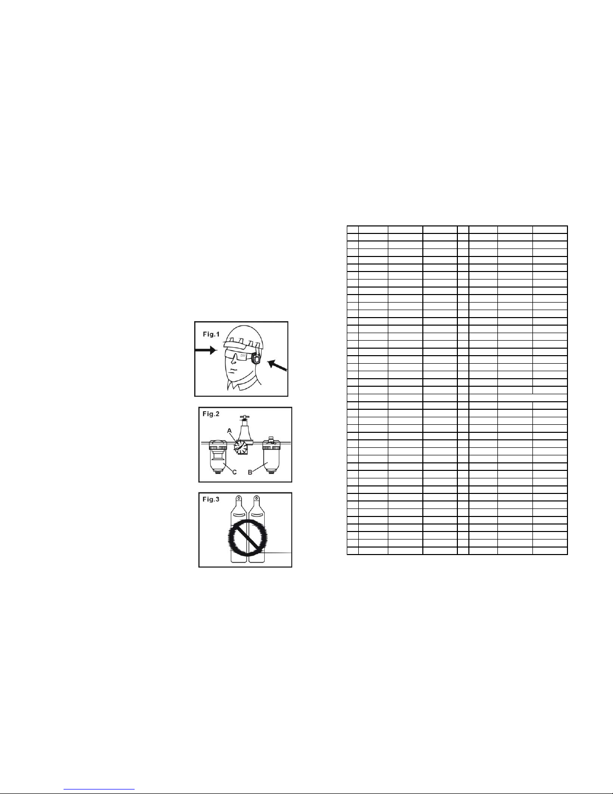
7. NEVER USE OXYGEN, CARBON
DIOXIDE, combustible gases or any other
bottled gas as a power source for this tool.
8. DO NOT CONNECT TOOL to pressure
that potentially exceeds 120 PSI (8.3 BAR).
9. ONLY USE AIR HOSE THAT IS
RATED for 150% of the maximum system
pressure. Please try to use 3/8” ID hose
connect in nailer with compressor.
10. DON’T OPERATE TO NEAR ANY
COMBUSTIBE or any other explosive
material. Don't operate the tool where it is easy
producing corrosion, rust or in a having heavy
powder environment.
11 DISONNECT TOOL FROM AIR
SUPLY HOSE before doing tool maintenance ,
clearing a jammed fastener, leaving work area,
moving tool to another location, or handing the
tool to another person..
12.ONLY DISCONNECT THE QUICK
CONNECTOR with the connector of the
body tail portion air inlet, no compressed
air can be guaranteed when disconnecting. If
operation is not coect , the tool can Remain
charged with air after being disconnected and
still be able to drive fastener, causing personal
injury.
13.REPLACE PARTS AND ACCESSORIES. Only allow use same replacement parts
while servicing. Approved accessories and
replacement parts are available.

- 4 -
14. BEFORE USING TOOL, carefully check if
there is any part damaged to obtain ideal results. Do
not use the tool if the tool has any air leaks,
uncompleted, damaged parts and needs repairing.
15. NEVER USE TOOL if safety, trigger or spring
is inoperable, missing or damaged. Do not alter or
remove safety, trigger or springs Make daily
inspections for free movement of trigger and safety
mechanism.
16.ONLY USE PARTS AND FASTENERS
recommended by us.
17. CONNECT TOOL TO AIR SUPPLY
BEFORE loading fasteners to preventa fastener
from being fired during connection. The tool
driving mechanism may cycle when tool is
connected to the air supply. When not in use
remove all fasteners from the nail housing.
18. AL WAYS ASSUME THE TOOL CONTAINS
FASTENERS. Keep the tool pointed away from
yourself and others at all times. No horseplay.
Respect the tool as a working implement.
19. DO NOT LOAD FASTENERS with trigger or
safety depressed to prevent unintentional firing of a
fastener.
20. REMOVE FINGER FROM TRIGGER when
not driving fasteners. Never carry tool with finger
on trigger: tool will fire fastener if safety is bumped
while trigger is depressed.
21. DON'T OVER REACH. Keep proper footing
and balance at all times when using or handling the
tool.
22. FIRE FASTENERS INTO WORK
SURFACE ONLY: NEVER into materials too hard
to penetrate.
PROBLEM CAUSE SOLUTION
Skipping
fasteners/ feeding
intermittently
1.Having the foreign matters
between the small piston and
small cylinder.
2.O-ring on the small piston is
worn and damaged.
3.Tool dry and lack lubrication.
4.The spring on the small piston is
damaged.
5.Air pressure is lower.
6.Connecting screw of nose and
body is loose.
7.Stopped hook can't stop the
fasteners.
8.Bent fasteners.
9.Wrong size fasteners.
10.Small piston bumper is worm
and damaged.
11.Feed hook is binding.
12.Nail length is not correct with
loading space of nail housing.
13.Weld wires in nail coil is broken.
1.Disassemble/ clean/lubricate.
2.Check/replace O-ring/lubricate
3.Use pneumatic tool oil.
4.Replace small piston the spring.
5.Increase the air pressure, but
don't exceed 120 PSI (8.3 bar).
6.Tighten all screw.
7.Replace taper spring of the
stopped hook.
8.Use recommended fasteners.
9.Use recommended fasteners
10.Replace bumper and lubricate
small piston.
11.Clean feed hook and torsion
spring.
12.Adjust adjuster plate at the nail
housing tail portion according to
the recommended nail length to
make arrow on the nail housing
tail pointing to correct direction.
13.Stop using.
Runs slowly or has
power loss
1. Tool dry, lacks lubricate ion
2. The spring in the cylinder cap is
damaged.
3.Having foreign matters between
piston assembly and cylinder.
4.Have not assembled the cylinder to
home position.
5.O-ring on the valve is dry after
disassembly.
6.Air pressure is too low.
7.Driver is worn (sort)
8. Inner diameter of hose is small.
1.Use pneumatic ic tool oil.
2.Replace the spring in the cylinder
cap.
3.Disassemble/clean/lubricate.
4.Reassemble af ter disassembling.
5.Reassemble af ter lubricating
6. Increase the air pressure, but don't
exceed 120 PSI (8.3 bar).
7.Replace piston assembly.
8.Use bigger inner diameter of the
hose.
Fasteners are jammed 1.Fasteners are wrong size.
2.Weld wires in nai l coil are broken.
1.Use recommended fasteners.
2.Stop using.

- 5 -
SERVICE AND REPAIR
All quality tools eventually require servicing of replacement parts due to wear
from normal use. Some user serviceable components are described in the
TROUBLE SHOOTING Section. All repairs made by local agencies are fully
guaranteed against defective material and workmanship. We cannot guarantee
repairs made or attempted by anyone other than these agencies.
Should you have any questions about your tool , please conta ct with us at any
time. In any communications, please give all information shown on the
nameplate of your tool (model number, type, serial number, etc.)
TROUBLESHOOTING
CAUTION: Disconnect tool from air supply before perform i ng
any service procedure.
PROBLEM CAUSE SOLUTION
Air leaking at trigger
area
1. O-ring in trigger valve stem
is worn and damaged.
2. O-ring in trigger valve head is
worn and damaged.
3. Having foreign matters.
1.Check/replace O-ring/lubricate.
2.Check/replace O-ring/lubricate
3.Clean the tool/lubricate
Air leaking at the body
lower portion and nose
1.Screw is loose at connecting portion of the
nose and body.
2.O-ring is damaged between body and
nose.
3.Bumper is damaged.
4.Having the foreign matters at the
contacting portion of the bumper and body.
1.Tighten screw/recheck
2.Check/replace O-ring/lubricate
3. Replace the bumper.
4. Disassemble and clean
Air leaking at the body
upper portion and
cylinder
cap
1.Screw is loose at the connecting
portion of the cylinder and body .
2.Gasket is damaged.
1. Tighten the screw and recheck.
2. Replace the gasket.
Failure to start tool. 1.Tool dry, lack lubrication.
2.The spring in the cylinder cap is
damaged.
1. Use pneumatic tool oil
2.Replace the spring in the
cylinder cap.
Blade driving fasteners
too deeply
1.Safe bracket poison is not
correct.
2.Air pressure is too high.
1.Rotate knob of the adjuster to
move safe bracket down.
2.Decrease air pressure.
23. GRIP TOOL FIRMLY TO MAINTAIN
CONTROL
while allowing tool to recoil away from
work surface as fastener is driven. If safety bracket is
allowed to contact work surface again before trigger is
released, an unwanted fastener will be fired.
24. DO NOT DRIVE FASTENERS on
top of other fasteners, or with the tool at
too steep an angle: the fasteners can ricochet
causing personal injury.
25 . DO NOT DRIVE FASTENERS CLOSE
to the edge of the work piece. The work piece is
likely to split allowing the fastener to fly free or
ricochet causing personal injury.
26. KEEP ALERT. Watch what you are doing.
Use common sense. Do not operate any tool
when you are tired.
27. KEEP HANDS AND BODY PARTS
away from area shown in Fig. 13, to avoid
injury.
28. THIS TOOL IS EQUIPPED WITH
ADJUSTER
that can adjust driving depth. When
adjusting the driving depth, first disconnect from
air supply, rotate the knob of the adjuster by hand
until it is satisfactory .
29. WHEN NOT IN USE, cleaned and put it
back into the packing box. For sa fety, keep out
of reach of children.
EMPLOYER’S RESPONSIBILITIES
Employer must enforce compliance with the safety warnings and all other
instructions contained in this manual.
Keep this manual available for use by all people assigned to use this tool. For
personal safety and proper operation of this tool , read and follow all of these
instructions carefully.

- 6 -
FASTENERS SPECIFICATIONS
Only use recommended the fasteners.
TECHNICALPARAMETER
CHARACTERISTIC VALUE
Compressed Air pressure 70-120PSI (4.9-8.3bar)
Outline Dimension (L× H ×W) 332×132× 320 mm
Nail Length Range 1-1/2"--2-3/4"
Tool Weight 8.2 Ibs (3.7Kg)
Air Inlet 1/4"NPT
Air Consumption 0.13ft3/cycle at 100psi(at pressure
6.9bar, 3.8litre/cycle)
MAINTENANCE
CLEAN AND INSPECT DAILY
CAUTION: Disconnect tool from air supply before cleaning and inspection.
Correct all problems before operating.
Add pneumatic tool oil into the oiler regularly to remain the moving components
of the tool fine lubrication. Check the filter of the compressor weekly and switch
off manual valve to drain water and contaminations out.
Wipe the tool clean. Blow the tool clean by high compressed air, then use
non-flammable cleaning solutions to wipe exterior of tool only if necessary. Do
not soak tool with cleaning solutions. Su ch solutions can damage internal parts.
The exposed portion of the small piston rod and fe ed hook must kept clean.
Inspect trigger and safety mechanism to assure system is complete and
functional: no loose or missing parts, no binding or sticking parts shall be found.
Keep all screws tight. Loose screws can cause personal injury or damage tool.
Check if there are worn and damaged parts. If any, please replace immediately.
If tool is used without an in-line oiler: place 5 or 6 drops of porter-cable air tool
oil into the air inlet of the tool at the beginning of each workday.

- 7 -
USING THE TOOL
Complete all steps of PREPARING THE TOOL before using the tool.
This tool can be fired in two different ways:
1. Put the nose on the working surface, lightly push the tool toward the
working surface until the safe bracket is depressed, then, depress the trigger to
drive the fasteners. This “rigger fire” method provides the most accurate fastener
placement. In this method, the safe bracket can be adjusted downwards with
knob to avoid striking two nail at one time.
2. First, depress the trigger, then, repeatedly impact the safe bracket the tool can
repeatedly drive the fasteners. The tool will drive one fastener when the safe
bracket is impacted one time. This “bottom fire” method allows very fast
repetitive fastener placement.
CAUTION: Remove finger from trigger when not driving fasteners. Never
carry tool with finger on trigger: tool will fire a fastener if safety is bumped.
Keep tool pointed in a safe direction at all times.
Never attempt to drive a fastener into material that is too hard, or at too steep an
angle, or near the edge of the work piece. The fastener can ricochet causing
personal injury.
Disconnect tool from air supply before performing maintenance, clearing a
jammed fastener, leaving working area, moving tool to another location, or
handing the tool to another person. Cl ean and inspect tool daily. Carefully check
for proper operation of trigger and safety mechanism. Do not use the tool unless
both the trigger and the safety mechanism are functional or if the tool is leaking
air or needs any other repair.
PACKING LIST
DESCRIPTION Q'ty
MI CN70mm 1
S5 Hex Key 1
S6 Hex Key 1
Air Tool Oil 1
Safety glasses 1
Operating instruction 1
OPERAT ING INSTRUCTIONS
FOREWORD
MI CN-70MM is a heavy duty, coil fed, pneumatic nailer, using compressed air as
power source. It is designed to install 1-1/2”-2-3/4”or 0.091” -0.114” diameter nails
of various lengths. It is widely used for connection of frame and connection of
frame and felt.
POWER SOURCE
This tool is designed to operate on clean, dry, compressed air at regulated pressures
between 70 and 120 PSI(4.9 and 8.3 bar) (Pounds per Square Inch). The preferred
system would include a filter (C) Fig.2, a pressure regulator (A) Fig.2, and automatic
oiler (B) Fig.2 located as close to the tool as possible (withi n15 feet is ideal).
All compressed air contains moisture an d other conta minates that are d etrimental to
internal components of the tool. An air-line filter will remove most of these
contaminates and significantly prolong the life of

- 8 -
the tool. If an in-line oiler is not available: place five or six drops of oil, into the
tool’s air inlet at the beginning of each workday.
Only disconnect quick connector being connected with the connector of the body tail
portion air inlet, no compressed air can be guaranteed when disconnecting.
CAUTION: All line components (hoses, connectors, filters, regulators, etc.) must
meet 150% of the maximum system pressure.
Please try to use a hose of ID 3/8”onnectingnailer with compressor.
Do not connect this tool to a system with maximum potential. Only disconnect quick
connector being connected with the connector of the body tail portion air inlet, no
compressed air can be guaranteed when disconnecting.
Disconnect tool from air supply before performing maintenance, cl earing a jammed
fastener, leaving work area, moving tool to another location, or handing the tool to
another person.
PREPARING THE TOOL BEFORE DRIVING
1. After reading and understanding this entire manual, connect tool to
air supply.
CAUTION: Keep tool pointed away from yourself and others at all
times.
Always connect tool to air supply before loading fasteners.
Do not load fasteners with trigger or safety depressed.
Always wear Z87 approved safety glasses, and hearing protection
when preparing or operating the tool.
Never use a tool that leaks air or needs repair.
2. Depress Handle (See A Fig. 14) and op en the Latch. Rotate the
Upper Nail Housing to the side of the Body.
3. The Adjuster Plate can be moved up and down when twisting the
Adjuster Nut(see B Fig.15) . According to the length of nail, the Adjuster
Plate should be adjusted correctly to the position indicated inside
Lower Nail Housing.
4. Place a coil of nails over the Lower Nail Housing. Uncoil enough nails
to reach the Feed Hook and place the second nail between the teeth on
the Feed Hook. (see Fig. 16).
5. Close the Upper Nail Housing and depress the Latch (see Fig. 17).
 Loading...