

mundoclima UE-MUCSR-12-H8, UE-MUSTR-18-H8, MUCSR-12-H8, MUCR-12-H8, UE-MUCSR-18-H8 Service Manual
...
SUPER INVERTER H8
Service manual
MUCSR-H8
MUSTR-H8
MUCR-H8
MUCOR-H8
www.mundoclima.com
Thank you very much for purchasing our products.
Please read this manual carefully before installing
and using the unit.
CL20260 to CL20288
CL20395
English

Contents
Part 1 General Information .................................................................................................... 1
Part 2 Indoor Units ................................................................................................................. 5
Part 3 Outdoor Units ............................................................................................................ 94
Part 4 Installation ............................................................................................................... 108
Part 5 Electrical Control System ....................................................................................... 140
※The specifications, designs, and information in this book are subject to change without notice for
product improvement.
Contents i

General Information
Part 1
General Information
1. Model Lists ........................................................................................... 2
2. External Appearance ........................................................................... 3
2.1 Indoor Units ............................................................................................................... 3
2.2 Outdoor Units ............................................................................................................ 4
General Information 1

Model Lists
1. Model Lists
1.1 Indoor Units
R410A (capacity multiplied by 1000Btu/h)
Type Function 12 18 24 30 36 48 60
Super slim cassette Cooling and heating ● ● ● ● ●
Duct Cooling and heating ● ● ● ● ● ● ●
Ceiling-floor Cooling and heating ● ● ● ● ● ●
Four-way
cassette(compact)
Floor standing Cooling and heating
1.2 Outdoor Units
Universal Outdoor unit Model
UE –
MUCR-12-H8 /
MUCSR-12-H8
UE –
MUCR-18-H8 /
MUCSR-18-H8 /
MUSTR-18-H8
UE –
MUCR-24-H8 /
MUCSR-24-H8 /
MUSTR-24-H8
UE –
MUCR-30-H8 /
MUCSR-30-H8 /
MUSTR-30-H8
UE –
MUCR-36-H8
/ MUCSR-36-H8
/ MUSTR-36-H8
UE - MUCR-48-H8 / MUCSR-48-H8 /
MUSTR-48-H8
UE –
MUCR-48-H8T /
MUCSR-48-H8T /
MUSTR-48-H8T
UE –
MUCR-60-H8T /
MUCSR-60-H8T /
MUSTR-60-H8T
Cooling and heating ● ●
Compressor
type
Rotary GMCC
Rotary GMCC
Rotary GMCC
Rotary GMCC
Rotary GMCC
Rotary GMCC
Rotary GMCC
Rotary GMCC
Compressor
Brand
●
Matched indoor units
MUCR-12-H8
MUCSR-12-H8
MUCSR-18-H8
MUCR-18-H8
MUSTR-18-H8
MUCSR-24-H8
MUCR-24-H8
MUSTR-24-H8
MUCSR-30-H8
MUSTR-30-H8
MUCR-30-H8
MUCSR-36-H8
MUCR-36-H8
MUSTR-36-H8
MUCSR-48-H8 /
MUCSR-48-H8T
MUSTR-48-H8 /
MUSTR-48-H8T
MUCR-48-H8 / MUCR-48-H8T
MUCOR-60-H8T
MUCSR-60-H8 /
MUCSR-60-H8T
MUCR-60-H8 / MUCR-60-H8T
MUSTR-60-H8 /
MUSTR-60-H8T
General Information 2
External Appearance
2. External Appearance
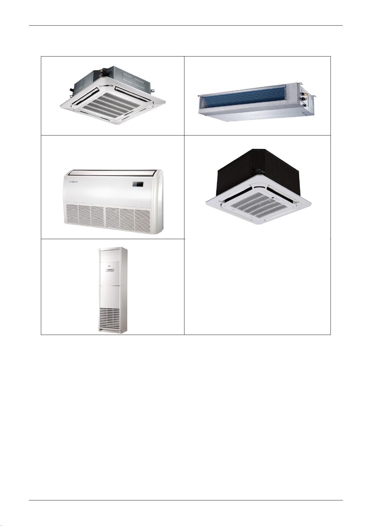
2.1 Indoor Units
Super slim cassette
Duct
Ceiling-Floor
Floor standing
Compact Four-way cassette
General Information 3
External Appearance
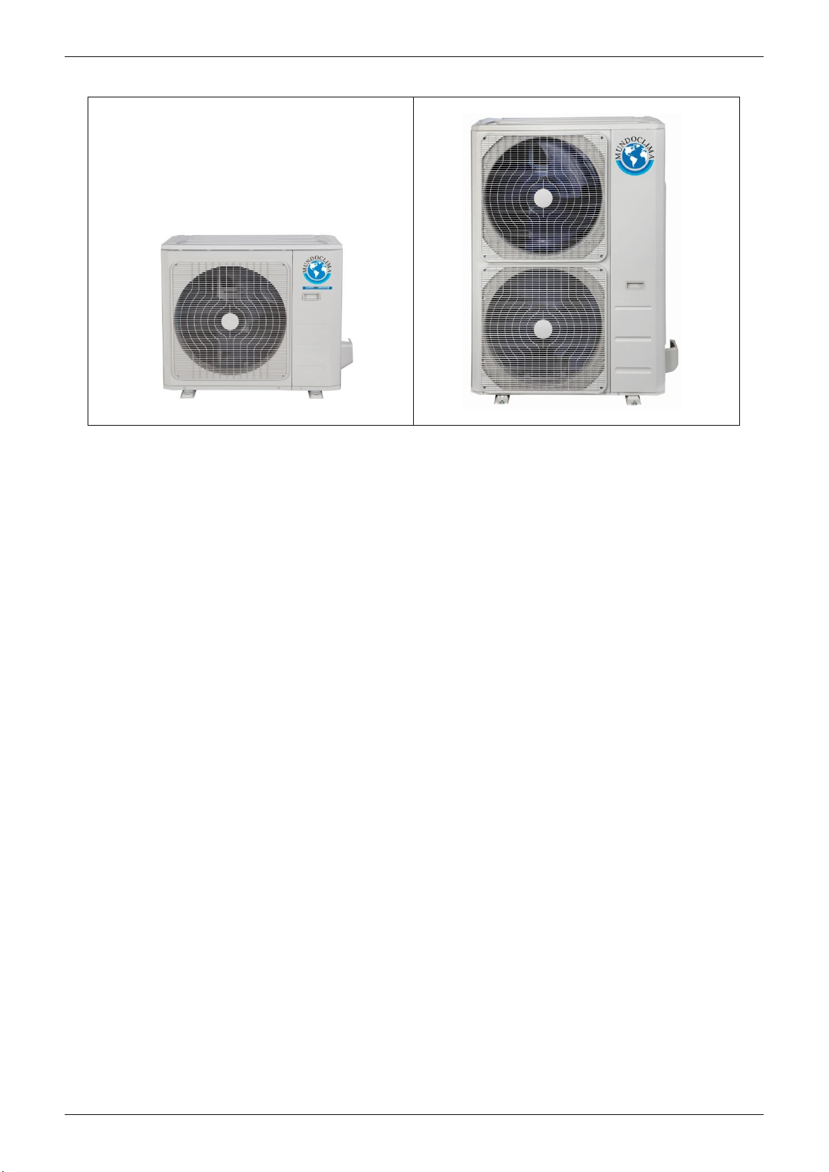
2.2 Outdoor Units
Single fan outdoor unit (Models 12 to 36)
Double fan outdoor unit (Models 48 to 60)
General Information 4

Indoor Units
Part 2
Indoor Units
MUCSR-H8 (24 to 60) Cassette Type ……………………6
MUCR-H8 Duct Type ………………………..…………… ..46
MUSTR-H8 Ceiling & Floor Type ....................................... 49
MUCSR-H8 (12 to 12) Cassette Type (Compact) ............. 68
MUCOR-H8 Floor standing Type ...................................... 82
Indoor Units 5

MUCSR-H8 (24 to 60) Cassette Type
MUCSR-H8 (24 to 60) Cassette Type
1. Features ........................................................................... 7
2. Dimensions .................................................................... 10
3. Service Space ................................................................ 11
4. Wiring Diagrams ............................................................ 12
5. Air Velocity Distributions (Reference Data) ................. 18
6. Electric Characteristics ................................................. 21
7. Sound Levels ................................................................. 22
8. Accessories .................................................................... 23
9. The Specification of Power ........................................... 24
10. Field Wiring .................................................................. 25
Indoor Units 6
Features
1. Features
1.1 Overview
Compact design, super slim body size, less space requiring in installation
Each louver can be separately controlled, more comfort air blowing is possible.
Auto-lifting panel design, more convenient to clean and maintain the filter. (optional)
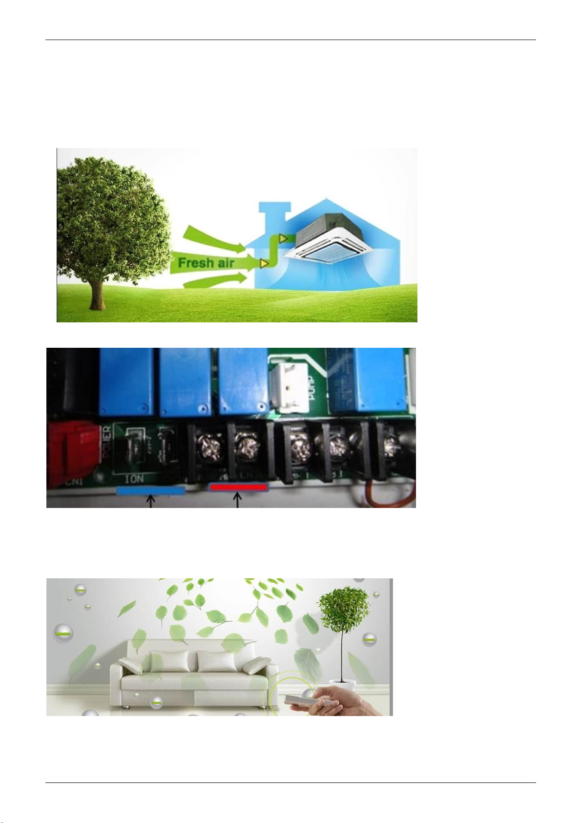
1.2 Fresh air intake function
Fresh air fulfills air quality more healthy and comfortable.
Ventilation motor is optional to increase the effect of fresh air.
1.3 Optional ionizer generator
Ionizer generator is optional to get refreshing air to your room.
Ionizer can be switched on or off by remote controller.
When pressing the Clean Air button on the remote controller, Ionizer will work and the indicator light on
display board will shine.
Ionizer generator
connector
Ventilation motor
connector
Indoor Units 7

Features
1.4 Built-in draining pump
Due to the improvement of structure, more convenient to repair or replace the draining pump.
Built-in draining pump to make sure condensed water drain out reliably.
Draining Pump
1.5 Terminals for alarm lamp and long-distance on-off controller connection are
standard
Reserve terminals for the connection of alarm lamp and long-distance on-off controller, more human
control.
Indoor Units 8
Alarm lamp
Long-distance on-off controller

Features
1.6 Twins Combination (18k-30k)
The units can be installed as Twin systems: one outdoor unit can connect with two indoor units. The
indoor units can be combined in any of the different available ratings.
Indoor Units 9
Dimensions
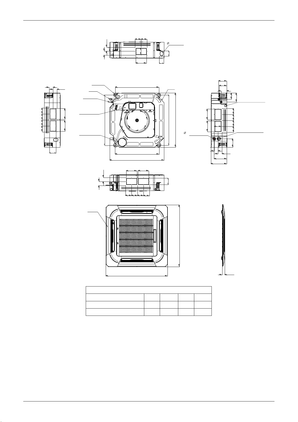
2. Dimensions
D
D
92 92
B
A
75
Fresh air intake
80
80
D
D
92
9292
92
A
A
B
4-install hanger
Gas side
Liquid side
E-parts box
Service hole for
draining pump
Panel
780
D
D
A
92 92
680
680
840
Body
780
840
32
Drain hole
A
B
92
92
136
126
91
90
Wiring connection port
135
A
B
A
D
196
92929292
Test mouth &
132
D
C
Test cover
950
950
Unit: mm
Model(kBtu/h) A B C D
24~36 160 95 245 60
48~60 160 95 287 60
55
Indoor Units 10
780(Hook-location)
880(Ceiling hole)
>2500mm
outlet intle t outlet
ground
Chart 1
No te:
880mm
Hook
B
Panel
Chart 2
Body
Bolt M6X12
180 00-24000Btu/h(R 22) Serie s A 26 0mm
36000-48000Btu/h(R 22) Series A 330mm
≥
≥
No te:
180 00- 24000B tu/ h(R 22) S eri es B= 240mm
3 60 00- 48000B tu /h(R 22) Series B= 310mm
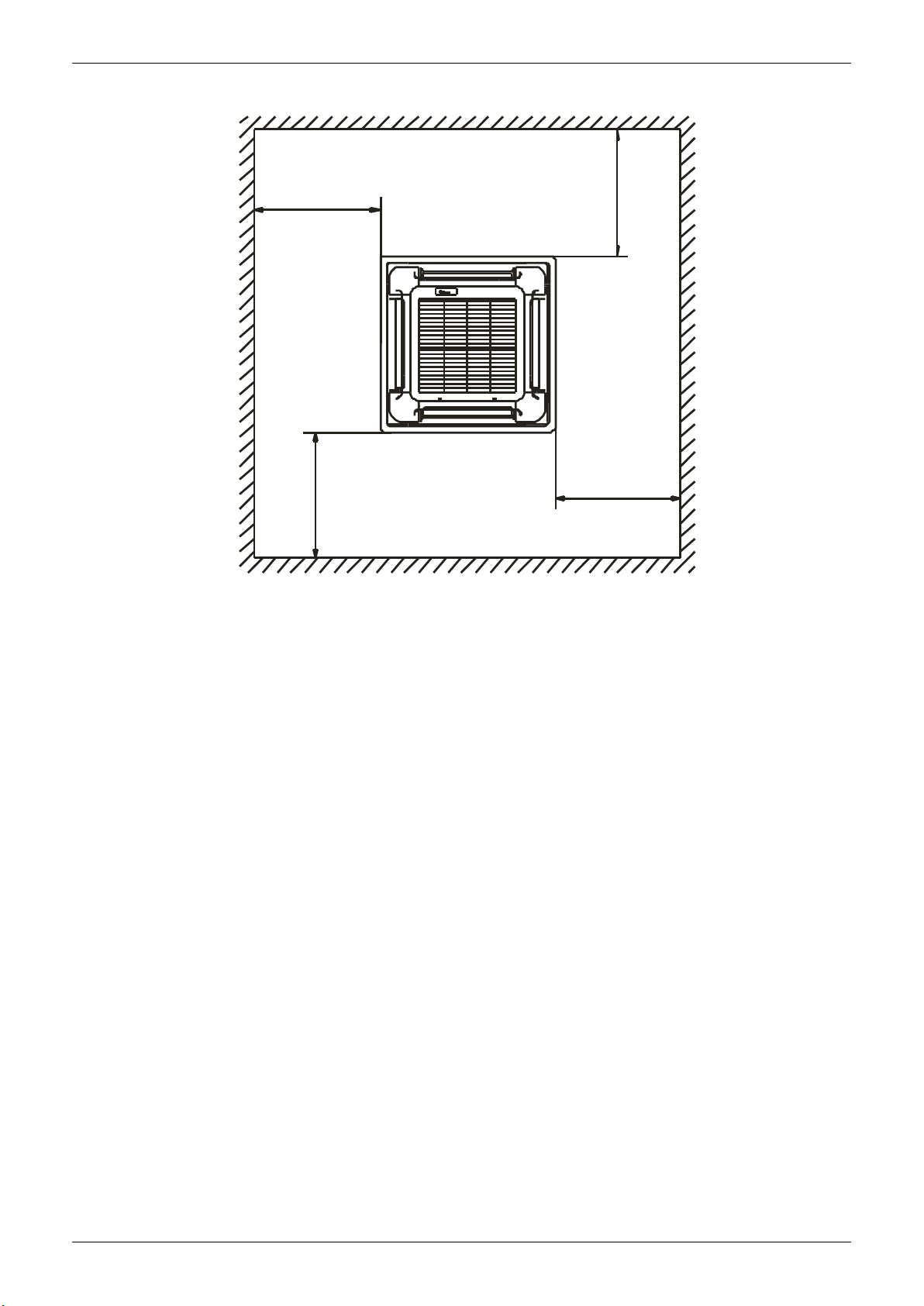
Service Space
3. Service Space
>1000mm
>1000mm
>1000mm
>1000mm
Indoor Units 11

Wiring Diagrams
4. Wiring Diagrams
CODE:16022500000803
FUNCTION OF SWITCH
FOR CCM UNIT ADDRESS
SWITCH
0
1
ON
F
2
E
S2
3
D
4
C
5
+
B
6
A
7
9
8
STATE
MODE
STATE
VALUE
0~15
0
F
E
D
C
B
A
9
8
32~47
SWIT CH
ON
SWIT CH
ON
1 2
1
ON
2
3
4
5
6
7
1 2
FOR AUT O-RES TART SE TTING
ON
REME MBER
FOR TE MP.COMP ENSATIO N
ON
1 2
6
S1
ADDRESS
Facto ry
Setti ng
S2
+
S1
ADDRESS
Facto ry
Setti ng
SW3
Fac tory
Set ting
SW6
Fac tory
Set ting
Anti-cold air
SW1
FAN MOTOR STOP-TEM
ON
24
1 2
Factory setting
ON
15
1 2
ON
8
1 2
Acc ordin g
ON
to th e
EEP ROM
1 2
set ting
This symbol indicates the - - - -
the actual element is optional,
shape shall prevail.
ON
0
1
F
2
E
3
D
4
C
5
B
6
A
7
9
8
1 2
16~31
ON
0
1
F
2
E
3
D
4
C
5
B
6
A
7
9
8
1 2
48~63
ON
NO_R EMEMB ER
ON
1 2
4
ON
ON
1 2
1 2
E fun ction
2
SWIT CH
SW2
ON
STATE
MODE
Fac tory
Set ting
SWIT CH
SW5
ON
STATE
MODE
NO SLAV E
Fac tory
Set ting
SWITCHENC1
NUMBER
4
5
6
7
8
9
A
FOR FAN M OTER CO NTROL
THEN NO P OWER RE QUEST .
ON
FAN OF F
FOR MA IN-SL AVE SETTI NG
ON
ON
ON
1 2
1 2
MAIN
MAIN
1 2
MAIN
(FOR POWER)
POWER
4000W-5300W£2.0HP£
5400W-7100W£2.5HP£
7500W-9000W £3.2HP£
9100W-10500W£4.0HP£
12000W-14000W(5.0HP)
14500W-16000W(6.0HP)
Reactor
ON
FAN ON
ON
1 2
SLAV E
/
Inn er Driv er
DC Mo tor
M
Y/G
RED
RED
TO SWING
BOARD
M
3
CN3
DC MO TOR
CN1
DRI VER MOD LE
Out er Driv er DC Mot or
Rem ote
Con trol
Ala rm
Out put
XS2
XP2
TO GO-UP-AND
-DOWN BOARD
5
CN1 3
JR6
XS2
XP2
MAGNETIC RING
5
CN1 5
ON - OF F
JR6
CN2 3
ALA RM
CN3 3
CN16
CN66
CN3
CN55
E Y X
To CCM
Com m.Bus
CN4 0
CN13
CN1 0(CN1 0A)
INDOO R UNIT
MAINB OARD
CN2
Q E P
CN1
S1
S2
RED (BROW N)
MAGNETIC RING
To OUTD OOR
Com m.Bus
L
CN5
BLU E(BLA CK)
N
CN14
CN8
4
CN7
CN6
Y/G
10
4
P1
P4
KJR-120C / WF-60A1
CON TROLL ER
XS9
XS10
M
NEW FAN
2
M
PUM P
DIS PLAY
BOA RD
OUTER PIPE TEMP.
BLA CK
WHI TE
WATER LEVEL SWITCH
Y/G
TO WI RE
XP9
XP10
KJR-12B / KJR-29B
5
CON TROLL ER
MIDDLE PIPE TEMP.
ROOM TEMP.
SWING
MOTOR
SWING
MOTOR
TO WI RE
T2B
T2
T1
Indoor Units 12
Wiring Diagrams
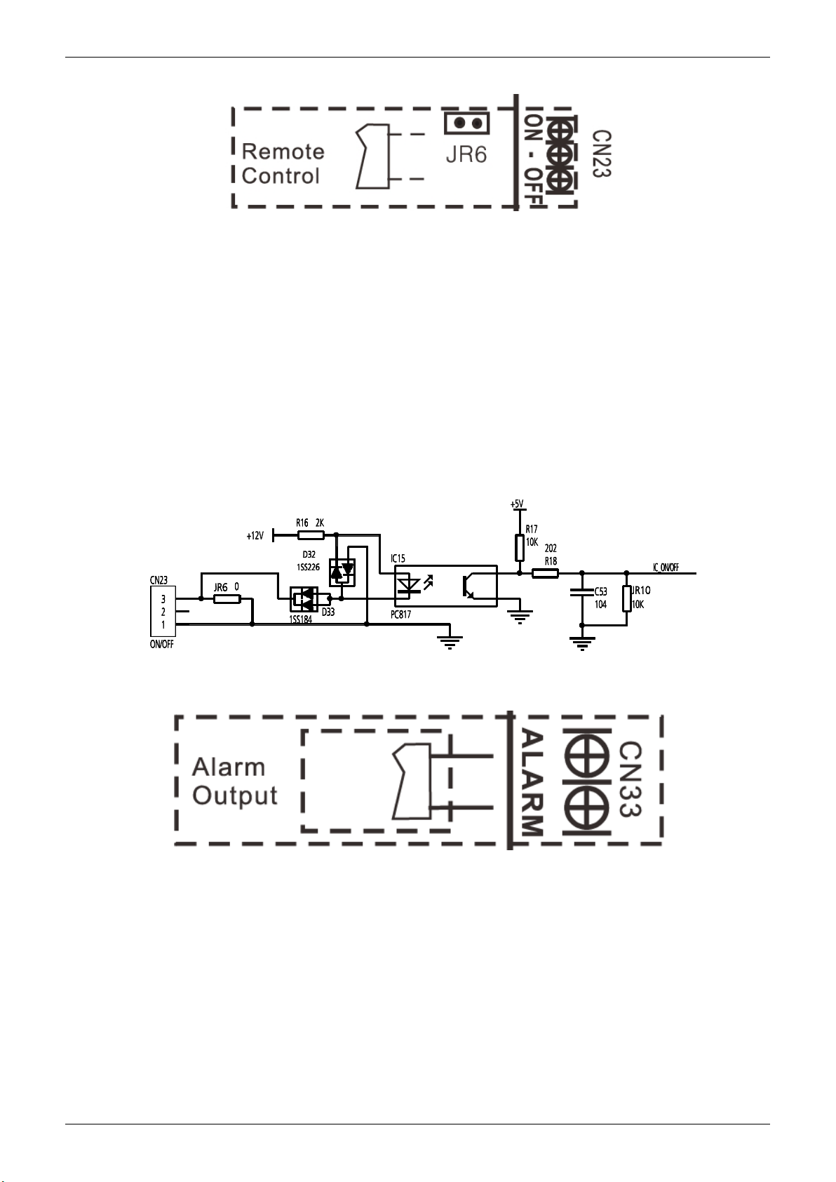
4.1 Some connectors introduce:
A For remote control (ON-OFF) terminal port CN23 and short connector of JR6
1. Remove the short connector of JR6 when you use ON-OFF function;
2. When remote switch off (OPEN), the unit would be off;
3. When remote switch on (CLOSE), the unit would be on;
4. When close/open the remote switch, the unit would be responded the demand within 2
seconds;
5. When the remote switch on. You can use remote controller/wire controller to select the mode
what you want; when the remote switch off, the unit would not respond the demand from remote
controller/wire controller.
When the remote switch off, but the remote controller/wire controller are on, CP code would be
shown on the display board.
6. The voltage of the port is 12V DC, design Max. current is 5mA.
B For ALARM terminal port CN33
1. Provide the terminal port to connect ALARM, but no voltage of the terminal port , the power
from the ALARM system (not from the unit )
2. Although design voltage can support higher voltage, but we strongly ask you connect the
power less than 24V, current less than 0.5A
3. When the unit occurs the problem, the relay would be closed, then ALARM works
Indoor Units 13
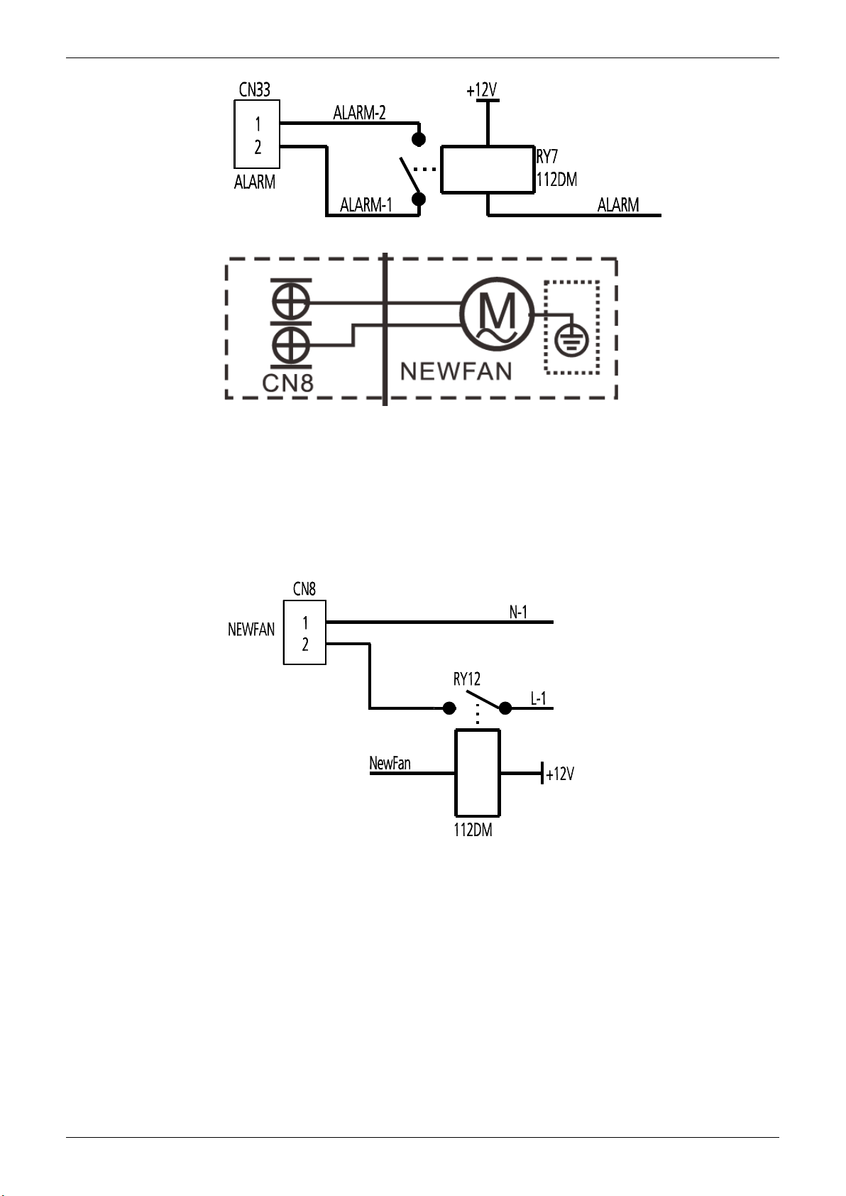
Wiring Diagrams
C. For new fresh motor terminal port CN8
1. Connect the fan motor to the port, no need care L/N of the motor;
2. The output voltage is the power supply;
3. The fresh motor cannot excess 200W or 1A, follow the smaller one;
4. The new fresh motor will be worked when the indoor fan motor work ;when the indoor fan
motor stops, the new fresh motor would be stopped;
5. When the unit enter force cooling mode or capacity testing mode, the fresh motor isn’t work.
Indoor Units 14
Wiring Diagrams
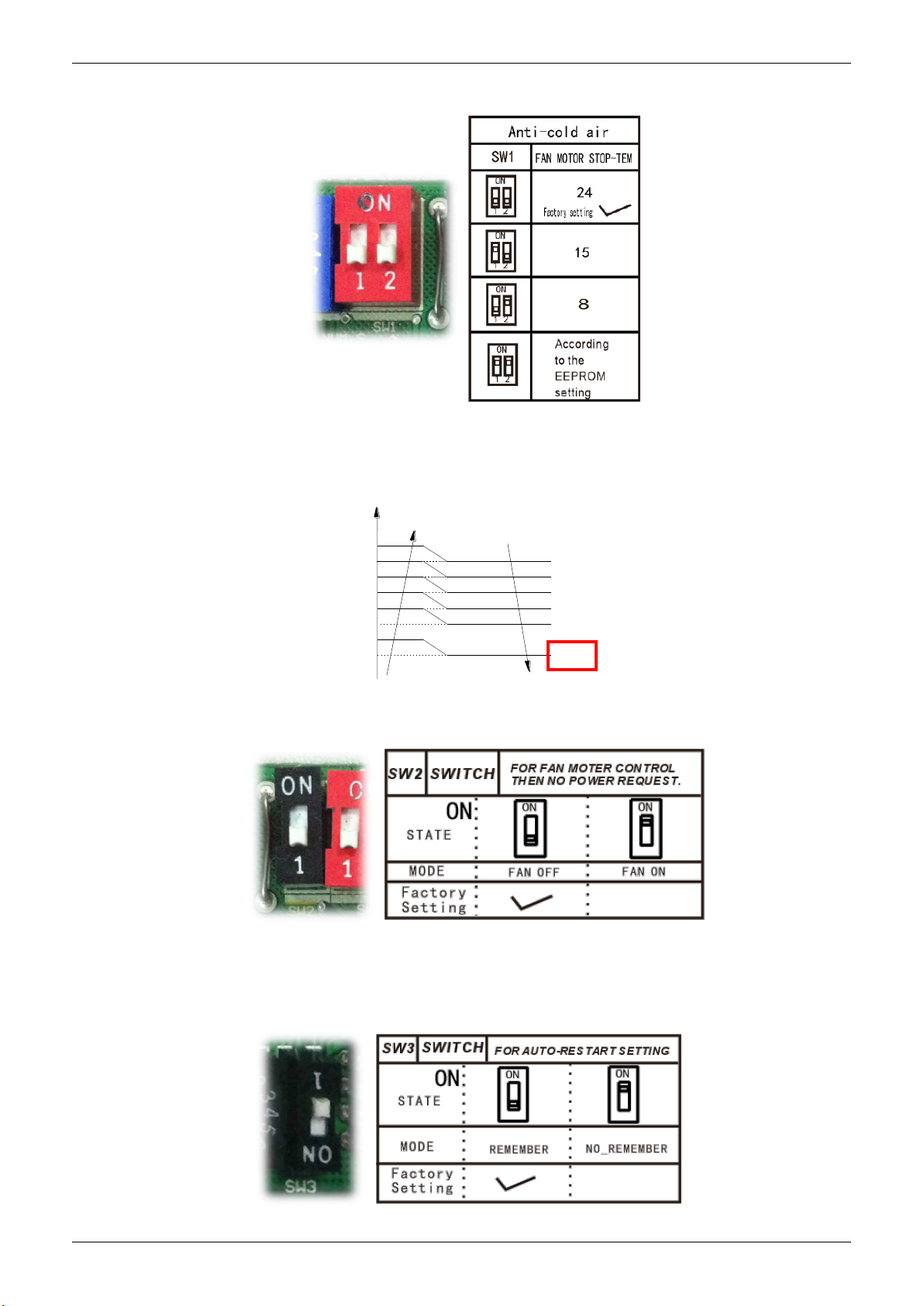
4.2
Micro-Switch Introduce:
A. Micro-switch SW1 is for selection of indoor fan stop temperature (TEL0) when it is in anti-cold
wind action in heating mode.
Range: 24oC, 15oC, 8 oC, according to EEROM setting (reserved for special customizing).
T2
TEL0+16
TEL0+14
TEL0+12
TEL0+10
TEL0+8
TEL0+6
Setting fan speed
H
M+
M
L
Super slow
Fan off
TEL0+12
TEL0+10
TEL0+8
TEL0+6
TEL0+4
TEL0
B.Micro-switch SW2 is for selection of indoor FAN ACTION if room temperature reaches the
setponit and the compressor stops.
Range: OFF (in 127s), Keep running.
Indoor Units 15
Wiring Diagrams
C.Micro-switch SW3 is for selection of auto-restart function.
Range: Active, inactive
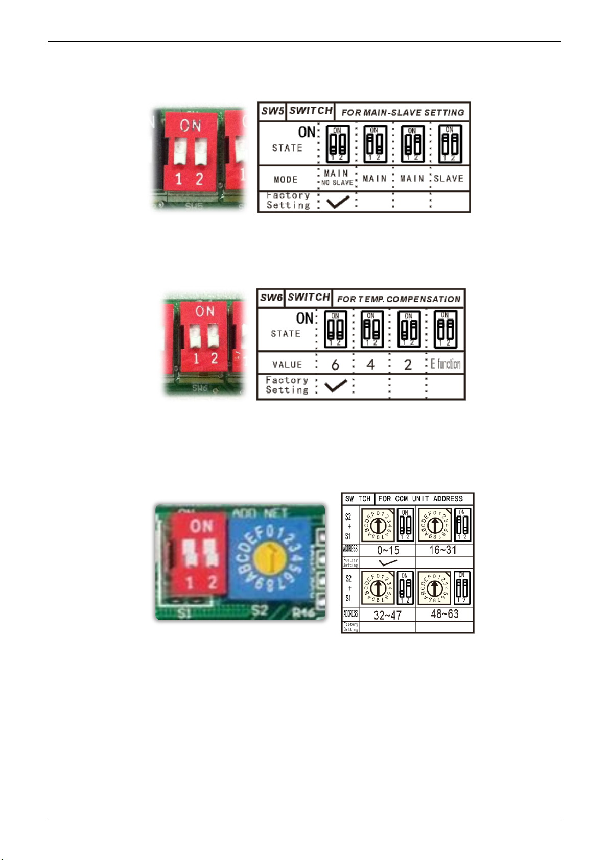
D. Micro-switch SW5 is for setting the master or slave unit when the unit is in twin connection.
Range: Master no slave (Normal 1 drive 1 connection), Master (2 positions without difference),
Slave
E.Micro-switch SW6 is for selection of temperature compensation in heating mode. This helps
to reduce the real temperature difference between ceiling and floor so that the unit could run
properly. If the height of installation is lower, smaller value could be chosen.
Range: 6oC, 4oC, 2oC, E function (reserved for special customizing)
F.Micro-switch S1 and dial-switch S2 are for address setting when you want to control this unit
by a central controller.
Range: 00-63
Indoor Units 16
Wiring Diagrams
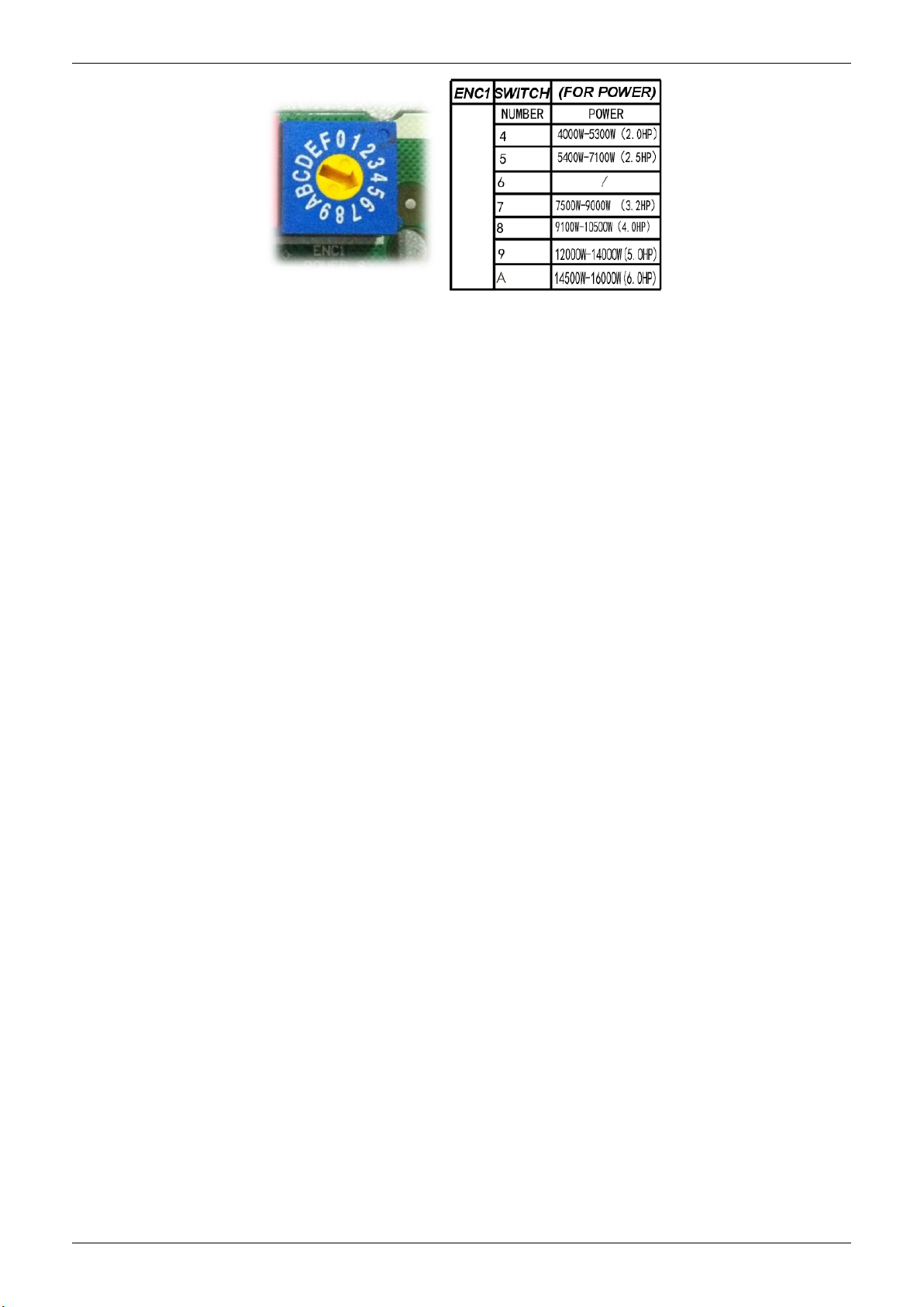
G. Dial-switch ENC1: The indoor PCB is universal designed for whole series units from 18K to
55K. This ENC1 setting will tell the main program what size the unit is.
NOTE: Usually there is glue on it because the switch position cannot be changed at random
unless you want to use this PCB as a spare part to use in another unit. Then you have to select
the right position to match the size of the unit.
Indoor Units 17
Air Velocity Distributions (Reference Data)
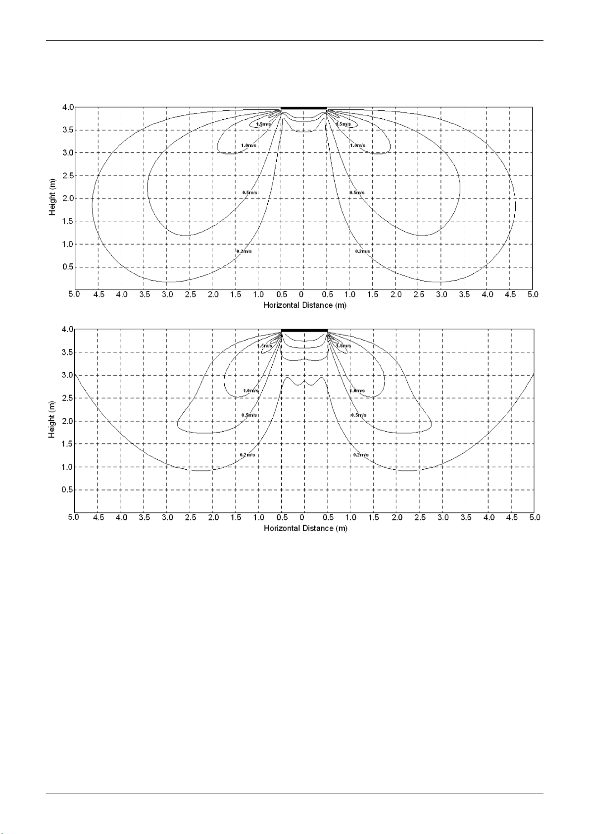
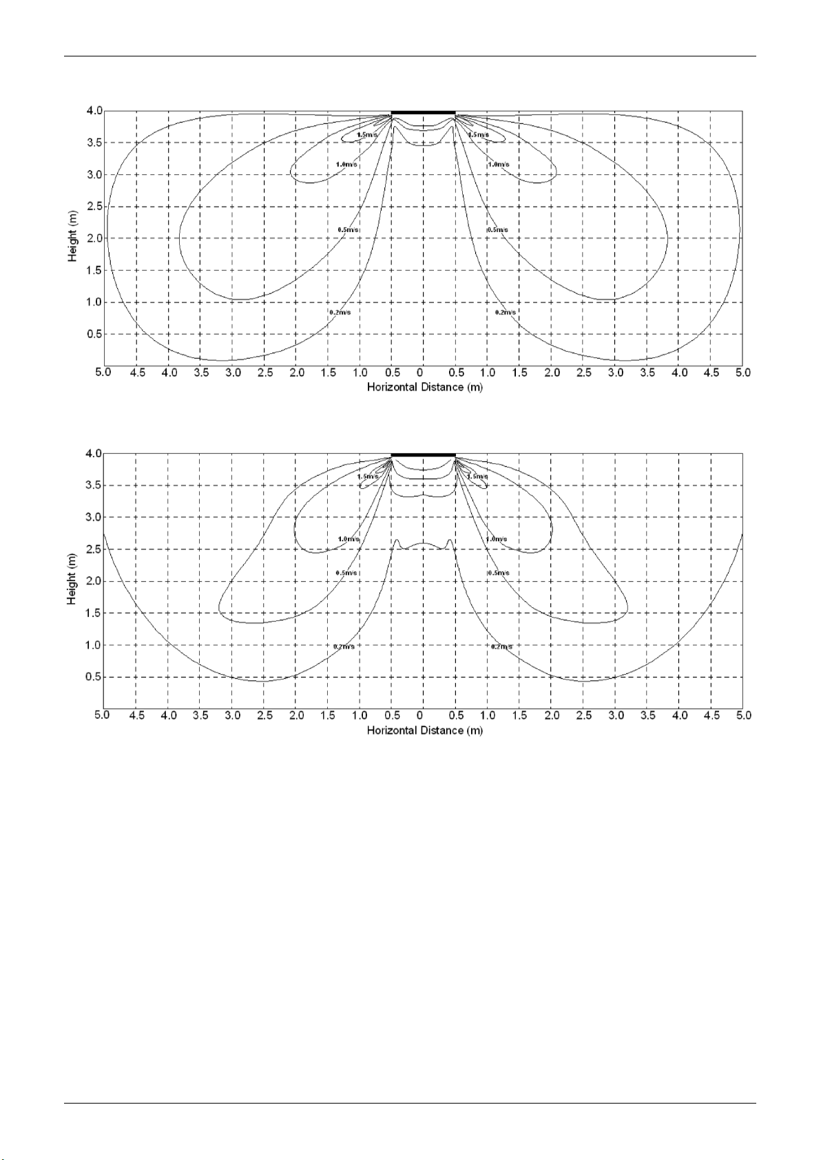
5. Air Velocity Distributions (Reference Data)
24K:
Cooling:
Heating:
Indoor Units 18
Air Velocity Distributions (Reference Data)
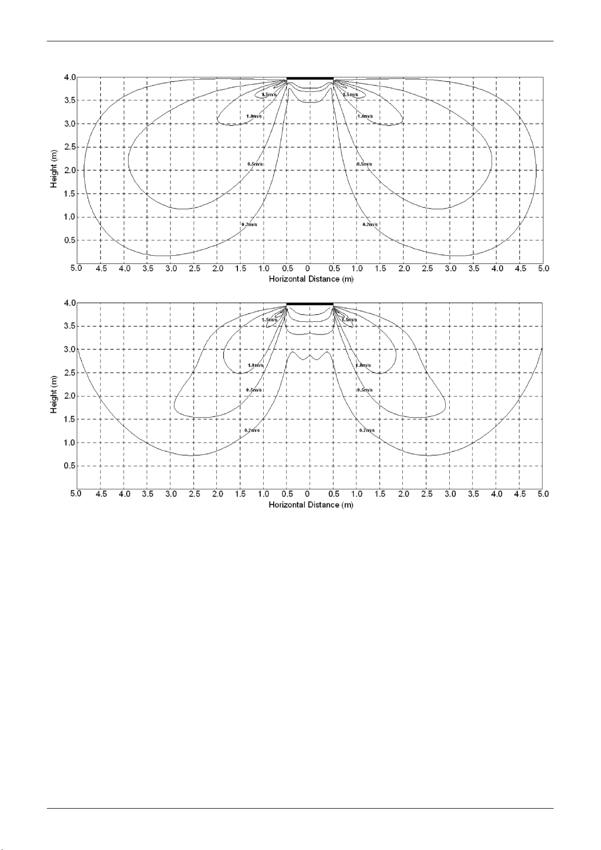
30-36K:
Cooling:
Heating:
Indoor Units 19
Air Velocity Distributions (Reference Data)
48-60K:
Cooling:
Heating:
Indoor Units 20

Electric Characteristics
6. Electric Characteristics
Model
MUCSR-24-H8 50 220-240V 198V 254V /
MUCSR-30-H8
MUCSR-36-H8 50 220-240V 198V 254V /
MUCSR-48-H8 / MUCSR-48-H8T 50 220-240V 198V 254V /
MUCSR-60-H8 / MUCSR-60-H8T 50 220-240V 198V 254V /
Hz Voltage Min Max MFA
50 220-240V 198V 254V /
Indoor Unit Power Supply
Notes:
MFA: Max. Fuse Amps. (A)
Indoor Units 21
Sound Levels
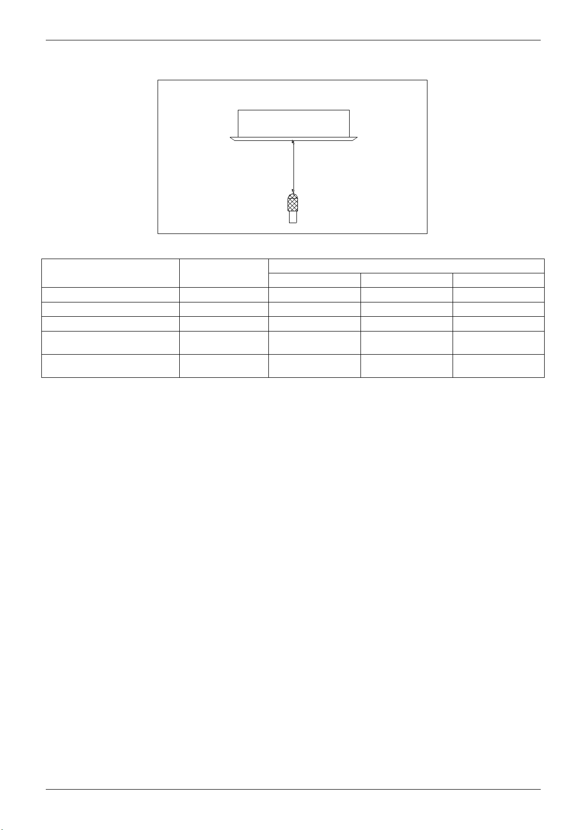
7. Sound Levels
1.4m
Microphone
MUCSR-24-H8
MUCSR-30-H8
MUCSR-36-H8
MUCSR-48-H8 /
MUCSR-48-H8T
MUCSR-60-H8 /
MUCSR-60-H8T
Model Noise Power dB(A)
62 46 42 39
65 53 48 44
65 56 52 48
65 55 51 48
69 52 49 46
Noise level dB(A)
H M L
Indoor Units 22
Accessories
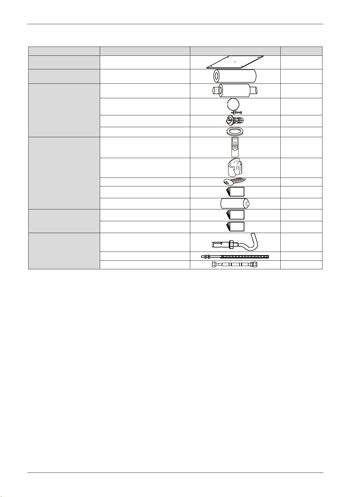
8. Accessories
Name Shape Quantity
Installation Fittings
Tubing & Fittings
Drainpipe Fittings
Remote controller & Its
Frame(The product you
have might not be
provided the following
accessories)
Others
Installation paper board
Soundproof / insulation sheath
Out-let pipe sheath
Out-let pipe clasp
Drain joint
Seal ring
Remote controller & Its Frame
Remote controller holder
Mounting screw(ST2.9×10-C-H)
Remote controller manual
Alkaline dry batteries (AM4)
Owner's manual
Installation manual
1
1
1
1
1
1
1
1
2
1
2
1
1
Installation accessory
(The product you have
might not be provided the
following accessories
Expansible hook
Installation hook
Orifice
4
4
1
Indoor Units 23
The Specification of Power
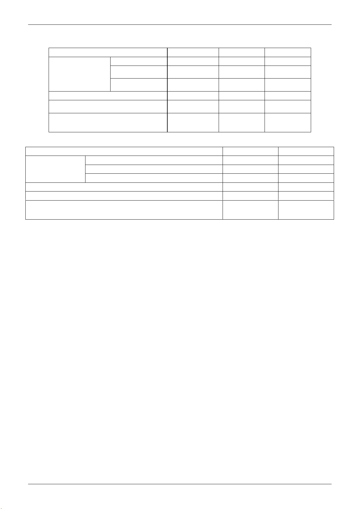
9. The Specification of Power
Model(Btu/h) 24000 30000 36000
Phase 1-phase 1-phase 1-phase
POWER
CIRCUIT BREAKER/Fuse (A) 30/20 40/30 40/30
Indoor/Outdoor Connecting Wiring
(Weak Electric Signal) (mm2)
Indoor/Outdoor Connecting Wiring
(Strong Electric Signal) (mm2)
Frequency and
Voltage
POWER WIRING
(mm2)
Model(Btu/h) 48000 48000~60000
Phase 1-phase 3-phase
POWER
Circuit Breaker/Fuse(A) 40/35 30/25
Indoor/Outdoor Connecting Wiring(Weak Electric Signal) (mm2) 2×0.2 2×0.2
Indoor/Outdoor Connecting Wiring(Strong Electric Signal) (mm2)
Frequency and Voltage 220-240V, 50Hz 380-415V, 50Hz
Power Wiring (mm2) 3×4.0 5×2.5
220-240V, 50Hz 220-240V, 50Hz 220-240V, 50Hz
3×2.5 3×2.5 3×4.0
2×0.2 2×0.2 2×0.2
3×1.0(3x2.5 with
auxiliary electric
heater)
3×1.0(3x2.5
with auxiliary
electric heater)
3×1.0(3x2.5 with
auxiliary electric
heater)
3×1.0(3x2.5
with auxiliary
electric heater)
3×1.0(3x2.5 with
auxiliary electric
heater)
Indoor Units 24
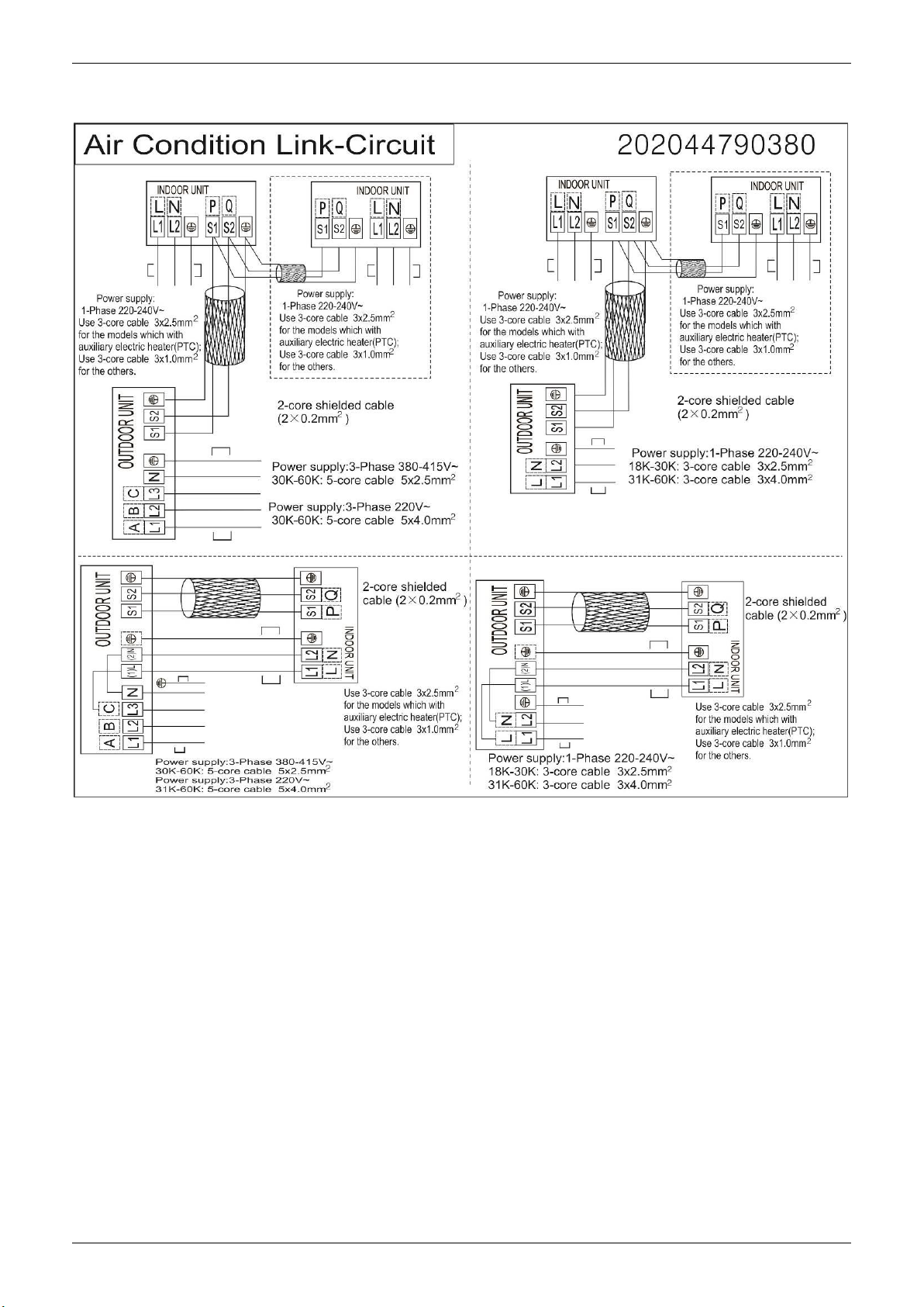
Field Wiring
10. Field Wiring
Indoor Units 25

MUCR-H8 Duct Type
MUCR-H8 Duct Type
1. Features .......................................................................... 27
2. Dimensions .................................................................... 30
3. Service Space ................................................................ 31
4. Wiring Diagrams ............................................................ 32
5. Static Pressure ............................................................... 38
6. Electric Characteristics ................................................. 44
7. Sound Levels ................................................................. 45
8. Accessories .................................................................... 46
9. The Specification of Power ........................................... 47
10. Field Wiring .................................................................. 48
Indoor Units 26
Features
1. Features
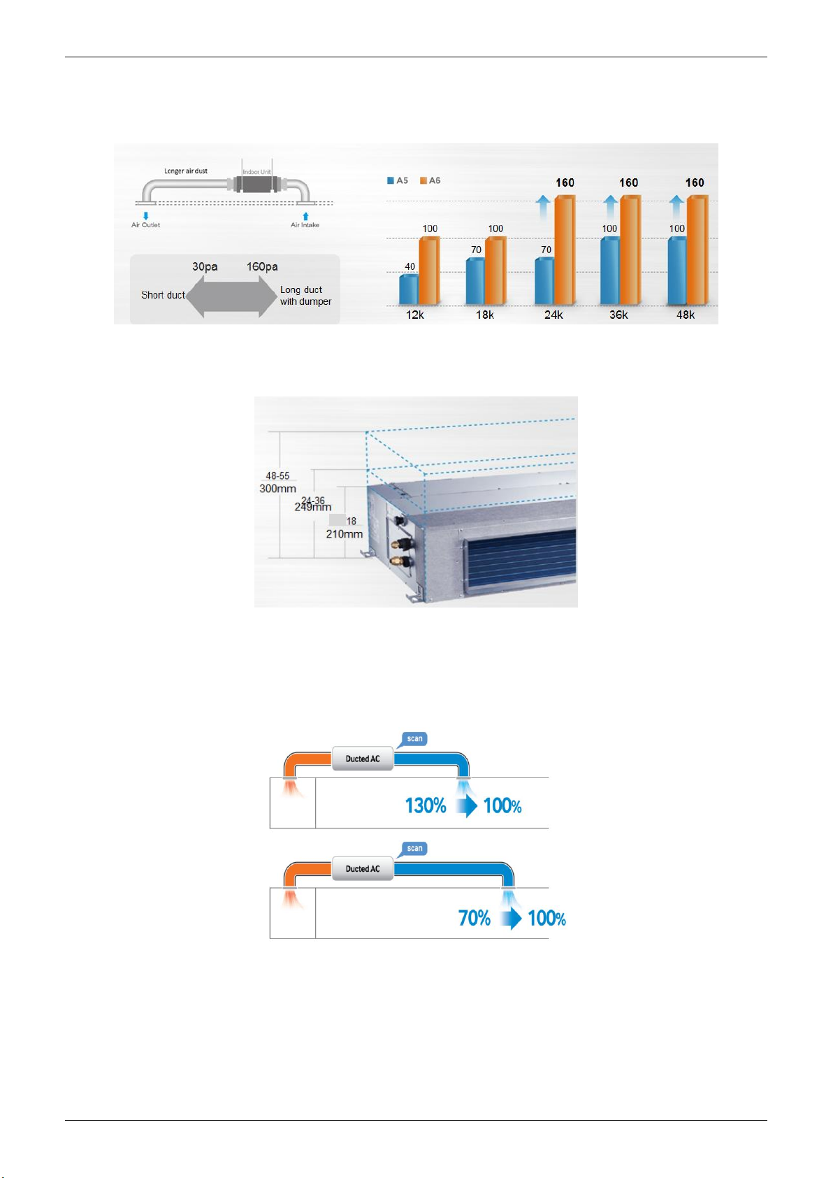
1.1 Higher Static Pressure
As a ducted air conditioner with medium static pressure, it has the widest static pressure range.
The maximum static pressure reaches 160 Pa
1.2 Slim Design
The industry lowest height is designed to be fitted into tight roof spaces.
*18K unit - 210mm,24K/36K unit - 249mm,48K unit -300mm
1.3 Constant air volume control
For ordinary duct, when the static pressure exceeds the expected range, it is fairly difficult even for an
experienced installer to calculate and adjust the air volume precisely.
With constant air volume control technology, the duct will automatically adjusts to perfect static pressure
and keep constant air volume.
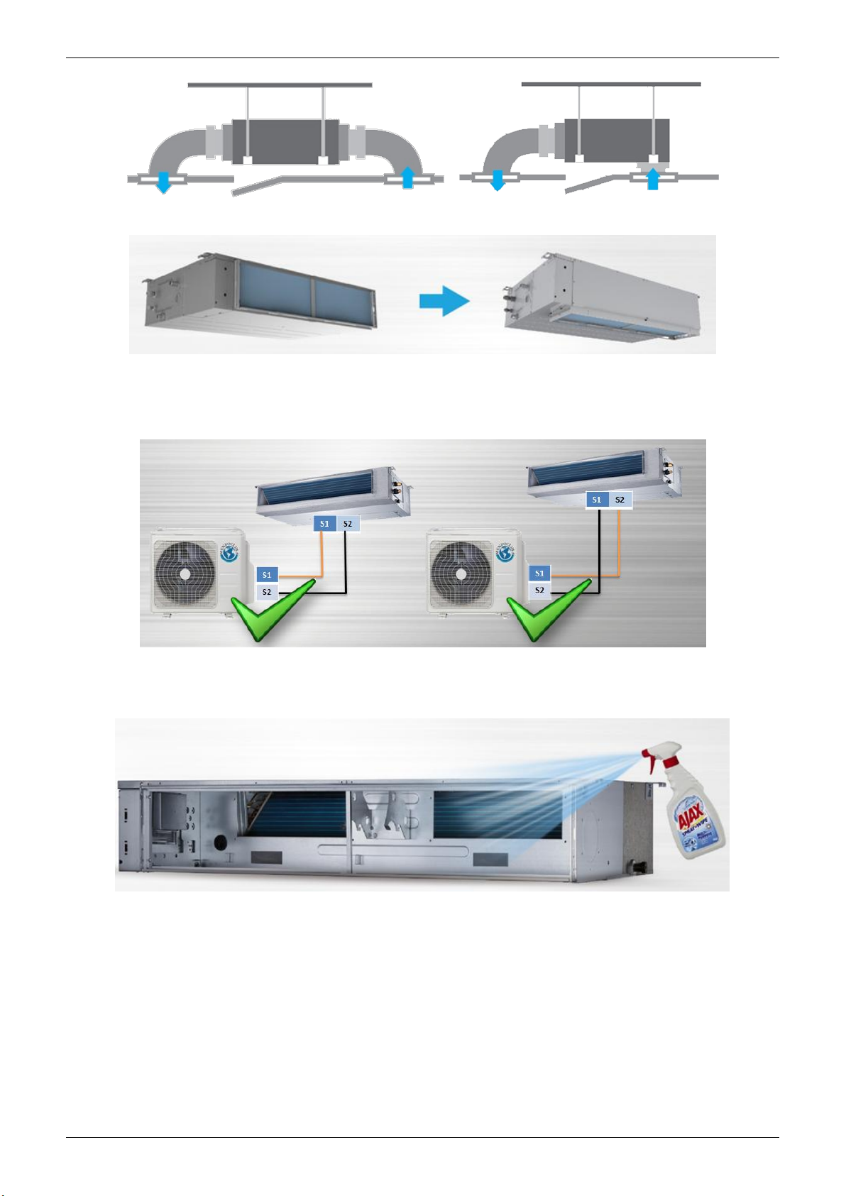
1.4 Flexible Air Intake Way (Bottom side or Rear side)
The frame size of air inlet in rear and bottom is the same. It’s very easy to switch to match different
application.
Indoor Units 27
Features
Air intake from rear (Standard)
Air intake from bottom (Optional)
1.5 Communication wire connection
MUCR-H8 uses two wires without polarity connection way, which almost has no mistake during the
installation.
1.6 Easy Clean
With a larger window design, once the motor and the blower wheels have been detached, heat
exchanger and water receiver tray in behind can be seen very clearly. Dust can be easily removed from
the inside by vacuum
Indoor Units 28
 Loading...