

mundoclima Aerotherm V17, SO30161, SO30162, SO30163, SO30164 Service Manual
...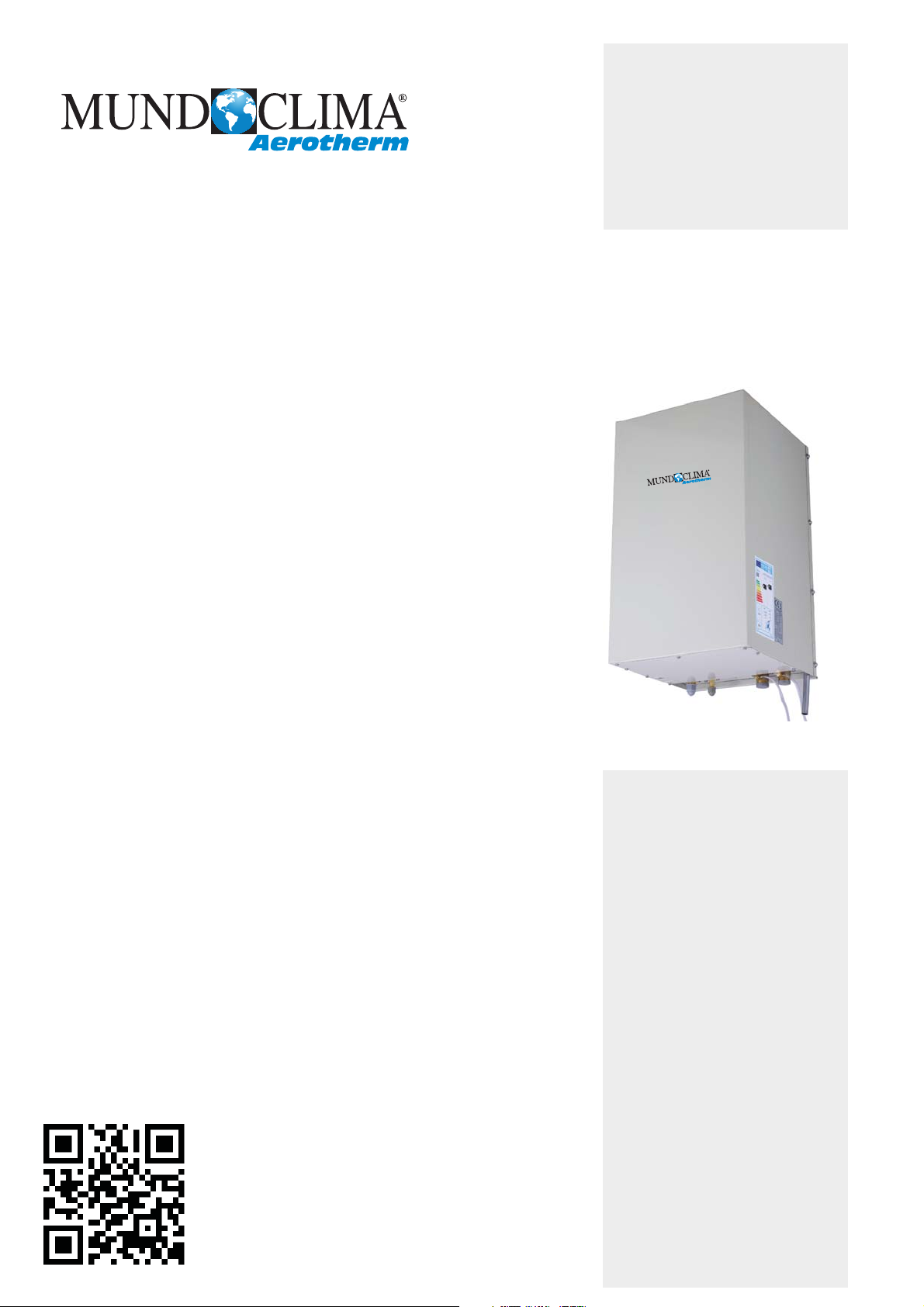
BIBLOC UNIT - AEROTHERM V17
Service Manual
www.mundoclima.com
Thank you very much for purchasing our product.
Before using your unit, please read this manual carefully
and keep it for future reference.
2nd Version
SO30160 to SO30172
English

CONTENTS
MUNDOCLIMA AEROTHERM V17 - BIBLOC
CONTENTS
Part 1 General Information ............................................................................ 3
Part 2 Component Layout and Refrigerant Circuits ..................................... 5
Part 3 Control ............................................................................................... 13
Part 4 Diagnosis and Troubleshooting ......................................................... 27
201703 1

MUNDOCLIMA AEROTHERM V17 - BIBLOC
2 201703

General Information
1 Unit Capacities ........................................................................................... 4
2 External Appearance .................................................................................. 5
MUNDOCLIMA AEROTHERM V17 - BIBLOC
Part 1
Part 1 - General Information
201703 3
1 Unit Capacities
Table 1-1.1: Capacity range
C
apacity
4kW
6kW
8kW
10kW
12kW
14kW
16kW
Capacity
12kW
14kW
16kW
Table 1-2.1: Capacity range
Capacity
8kW
16kW
16kW
Model
Compatible OU model
1.1 Outdoor Unit Capacities
MUNDOCLIMA AEROTHERM V17 - BIBLOC
BIBLOC
V17 (1Ph)
BIBLOC
V17 (3Ph)
SO30160
SO30167
1.2 Hydronic Box Capacities
SO30160 to SO30161
SO30161
SO30168
SO30170
SO30162
SO30169
SO30163 to SO30166
SO30163
SO30171
SO30164
SO30165
SO30166
SO30172
SO30167 to SO30169
4 201703

2 External Appearance
Table 1-2.1: Outdoor unit appearance
4/6kW
8kW
10/12/14/16kW
2.1 Outdoor Unit Appearance
MUNDOCLIMA AEROTHERM V17 - BIBLOC
2.2 Hydronic Box Appearance
Table 1-2.1: Hydronic box appearance
Part 1 - General Information
201703 5

Part 2 - Component Layout and Refrigerant Circuits
MUNDOCLIMA AEROTHERM V17 - BIBLOC
Part 2
Component Layout and
Refrigerant Circuits
1 Layout of Functional Components ......................................................... 6
2 Piping Diagrams .................................................................................... 9
3 Refrigerant Flow Diagrams .................................................................. 12
201703 5
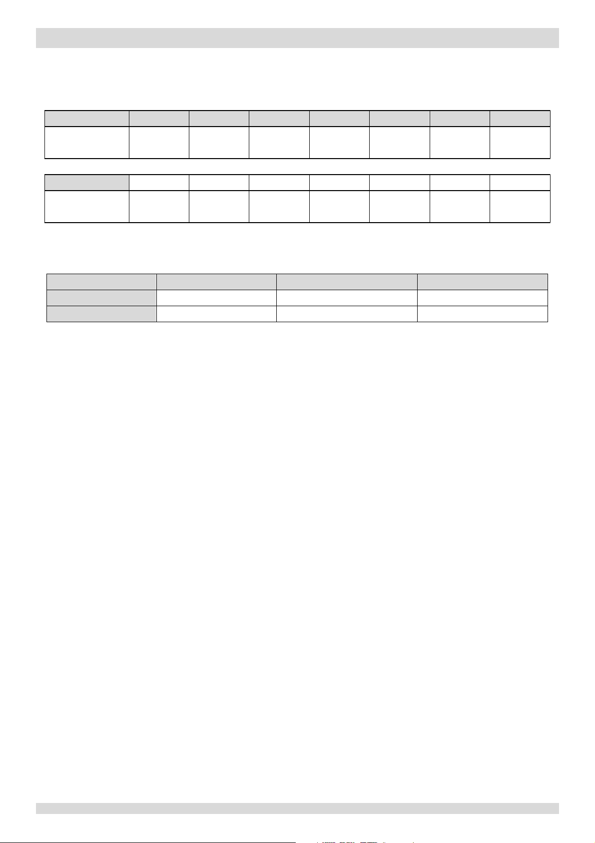
1 Layout of Functional Components
Figure 2-1.1:
top view
Figure 2-1.2:
front view
MUNDOCLIMA AEROTHERM V17 - BIBLOC
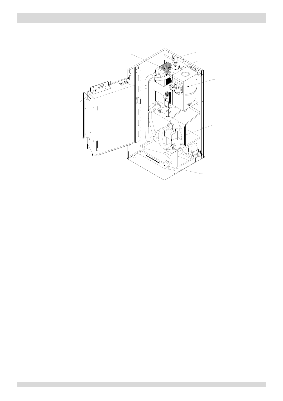
1.1 Outdoor Unit Layout
Models 4 to 8kW
Air side heat exchanger
Electronic expansion
valve
Liquid
G
ic control box
Electr
side stop valve
as side stop valve
Fan motor
4-
way valve
essure sensor
Pr
essure switch
Low pr
gh pressure switch
Hi
DC inverte
Accumulator
parator
Se
6 201703
r compressor
Part 2 - Component Layout and Refrigerant Circuits
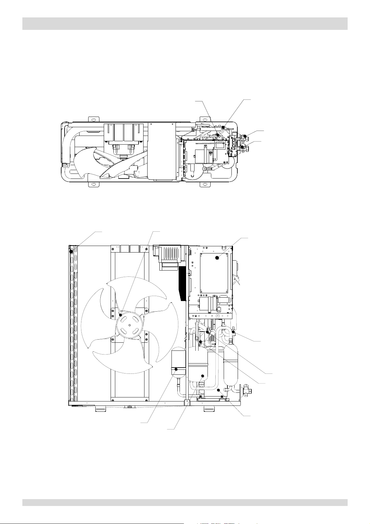
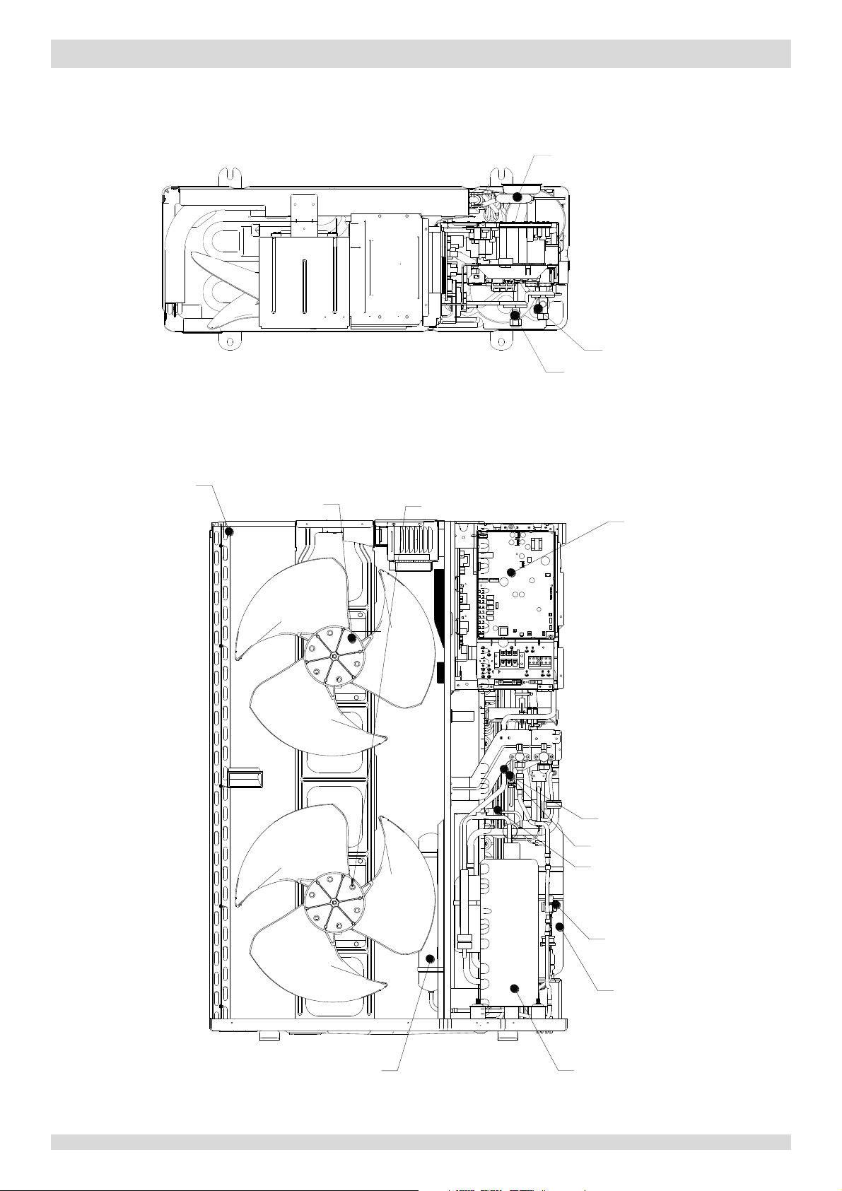
Figure 2-1.4:
top view
Figure 2-1.5:
front view
Models 10 to 16kW
MUNDOCLIMA AEROTHERM V17 - BIBLOC
Air side
heat exchanger
Upper fan motor
Lower fan motor
4-way val
Gas s
Liqui
d side stop valve
tric control box
Elec
ve
ide stop valve
Pressure
igh pressure switch
H
ow pressure switch
L
sensor
Electronic expansion valve
Separator
DC inverter compressorAccumulator
201703 7
1.2 Hydronic Box Layout
Figure 2-1.6:
oblique view
tric control box
Elec
Water si
de heat exchanger
MUNDOCLIMA AEROTHERM V17 - BIBLOC
r purge valve
Ai
ectric heater
Backup el
on vessel
Expansi
valve
Safety
ow switch
Water fl
mp
Water pu
nometer
Ma
8 201703
Part 2 - Component Layout and Refrigerant Circuits
2 Piping Diagrams
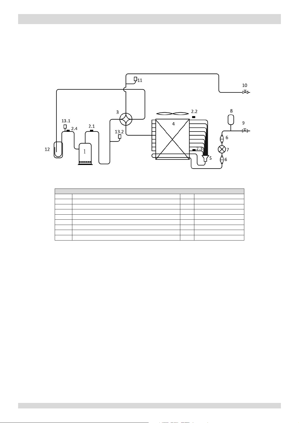
Figure 2-2.1:
piping diagram
Legend
1
Compressor
7
Electronic expansion valve
2.1
Discharge pipe temperature sensor
8
Accumulator
2.2
Outdoor ambient temperature sensor
9
Stop valve (liquid side)
2.3
Air side heat exchanger refrigerant outlet temperature sensor
10
Stop valve (gas side)
2.4
Suction pipe temperature sensor
11
Pressure sensor
3 4
-way valve
12
Separator
4
Air side heat exchanger
13.1
Low pressure switch
5
Distributor
13.2
High pressure switch
6
Filter
2.1 Outdoor Unit Piping
Models 4 to 8kW
MUNDOCLIMA AEROTHERM V17 - BIBLOC
Key components:
1. Accumulator:
Stores liquid refrigerant and oil to protect compressor from liquid hammering.
2. Electronic expansion valve (EXV):
Controls refrigerant flow and reduces refrigerant pressure.
3. Four-way valve:
Controls refrigerant flow direction. Closed in cooling mode and open in heating mode. When closed, the air side heat
exchanger functions as a condenser and water side heat exchanger functions as an evaporator; when open, the air
side heat exchanger functions as an evaporator and water side heat exchanger function as a condenser.
4. High and low pressure switches:
Regulate refrigerant system pressure. When refrigerant system pressure rises above the upper limit or falls below the
lower limit, the high or low pressure switches turn off, stopping the compressor.
5. Separator:
Separates liquid refrigerant from gas refrigerant to protect compressor from liquid hammering.
201703 9
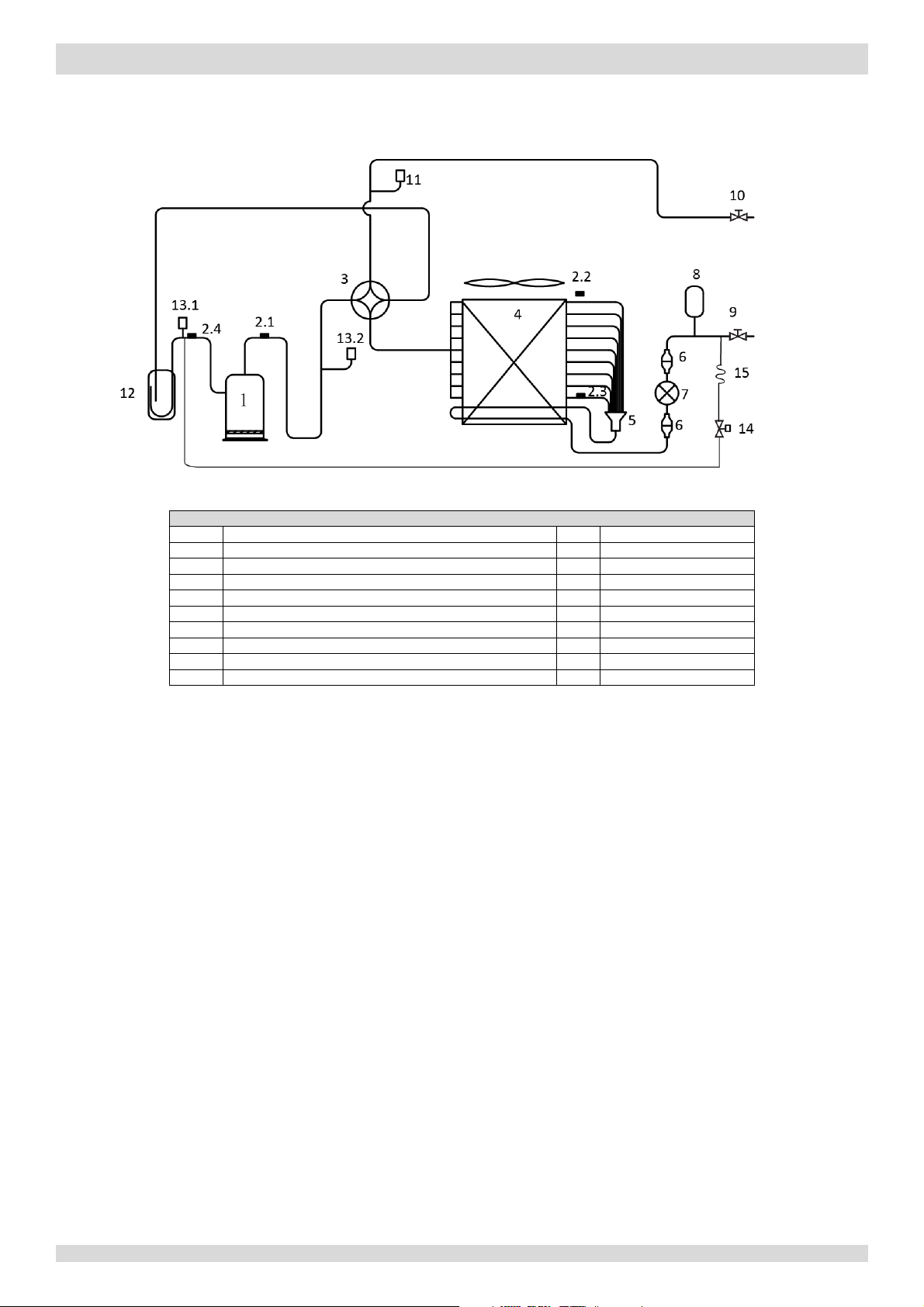
Figure 2-2.2:
piping diagram
Legend
1
Compressor
8
Accumulator
2.1
Discharge pipe temperature sensor
9
Stop valve (liquid side)
2.2
Outdoor ambient temperature sensor
10
Stop valve (gas side)
2.3
Air side heat exchanger refrigerant outlet temperature
sensor
11
Pressure sensor
2.4
Suction
pipe temperature sensor
12
Separator
3
4-way valve
13.1
Low pressure switch
4
Air side heat exchanger
13.2
High pressure switch
5
Distributor
14
Solenoid valve
6
Filter
15
Capillary
7
Electronic expansion valve
Models 10 to 16kW
MUNDOCLIMA AEROTHERM V17 - BIBLOC
Key components:
6. Accumulator:
7. Electronic expansion valve (EXV):
8. Four-way valve:
9. High and low pressure switches:
10. Separator:
11. Solenoid valve:
Stores liquid refrigerant and oil to protect compressor from liquid hammering.
Controls refrigerant flow and reduces refrigerant pressure.
Controls refrigerant flow direction. Closed in cooling mode and open in heating mode. When closed, the air side heat
exchanger functions as a condenser and water side heat exchanger functions as an evaporator; when open, the air
side heat exchanger functions as an evaporator and water side heat exchanger function as a condenser.
Regulate refrigerant system pressure. When refrigerant system pressure rises above the upper limit or falls below the
lower limit, the high or low pressure switches turn off, stopping the compressor.
Separates liquid refrigerant from gas refrigerant to protect compressor from liquid hammering.
Protects the compressor. If compressor discharge temperature rises above 100°C, 6. Solenoid valve opens and sprays a
small amount of liquid refrigerant to cool the compressor. Solenoid valve closes again once the discharge temperature
has fallen below 90°C.
10 201703

Part 2 - Component Layout and Refrigerant Circuits
2.2 Hydronic box Piping
Figure 2-2.1:
piping diagram
Legend
1
Air purge valve
2
Backup electric heater
Expansion vessel
Refrigerant liquid
13.2
Water side heat exchanger refrigerant inlet (liquid pipe) temperature
sensor
5
Refrigerant gas side
13.3
Water side heat exchanger water outlet temperature sensor
6
Water side heat exchanger
13.4
Water side heat exchanger water inlet temperature sensor
7
Water flow switch
13.5
Backup electric heater water outlet temperature sensor
8
Water pump
14.1
Anti-frozen electric heater for water side heat exchanger
9
Manometer
14.2
Anti-frozen electric heater for water inlet pipe
10
Safety valve
MUNDOCLIMA AEROTHERM V17 - BIBLOC
11 Water outlet
12 Water inlet
3
4
13.1
side
Water side heat exchanger refrigerant outlet (gas pipe) temperature
sensor
Key components:
1. Air purge valve:
Automatically removes air from the water circuit.
2. Safety valve:
Prevents excessive water pressure by opening at 43.5 psi (3 bar) and discharging water from the water circuit.
3. Expansion vessel:
Balances water system pressure. (Expansion vessel volume: 3L.)
4. Water flow switch:
Detects water flow rate to protect compressor and water pump in the event of insufficient water flow.
5. Backup electric heater:
Provides additional heating capacity when the heating capacity of the heat pump is insufficient due to very low
outdoor temperature. Also protects the external water piping from freezing.
6. Manometer:
Provides water circuit pressure readout.
7. Water pump:
Circulates water in the water circuit.
201703 11
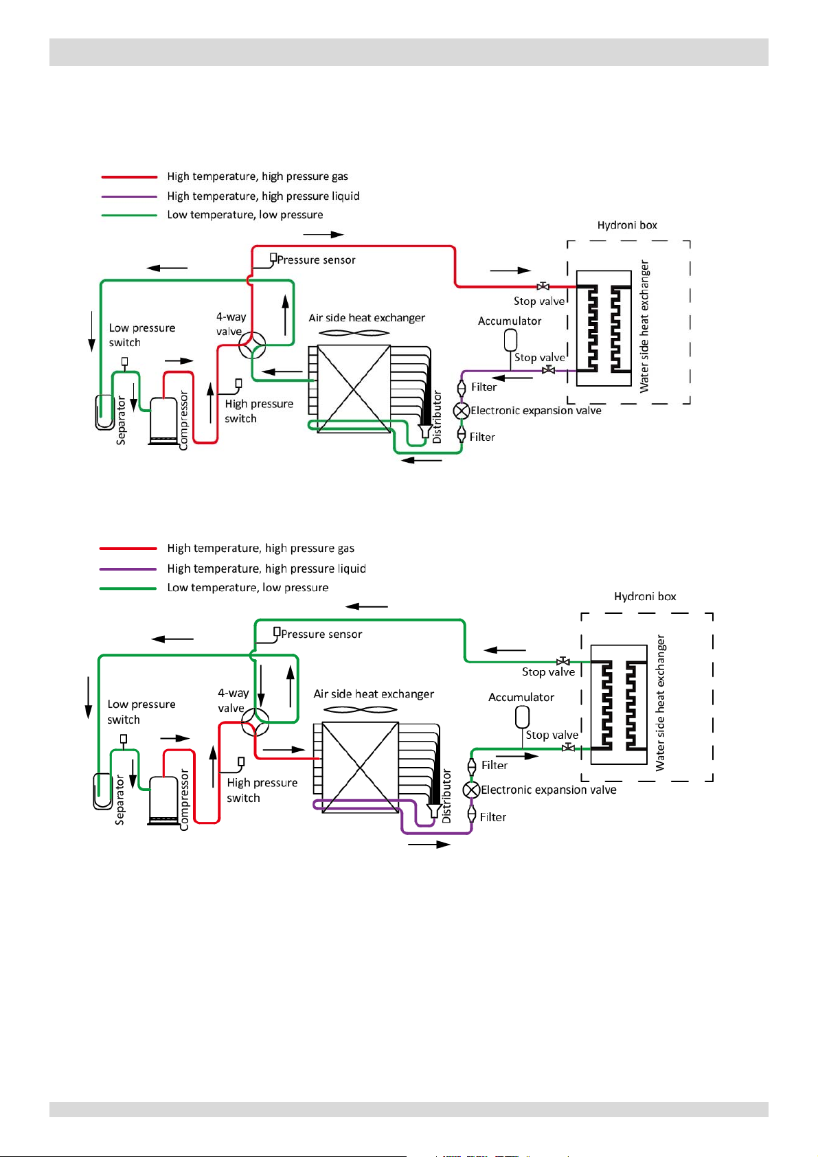
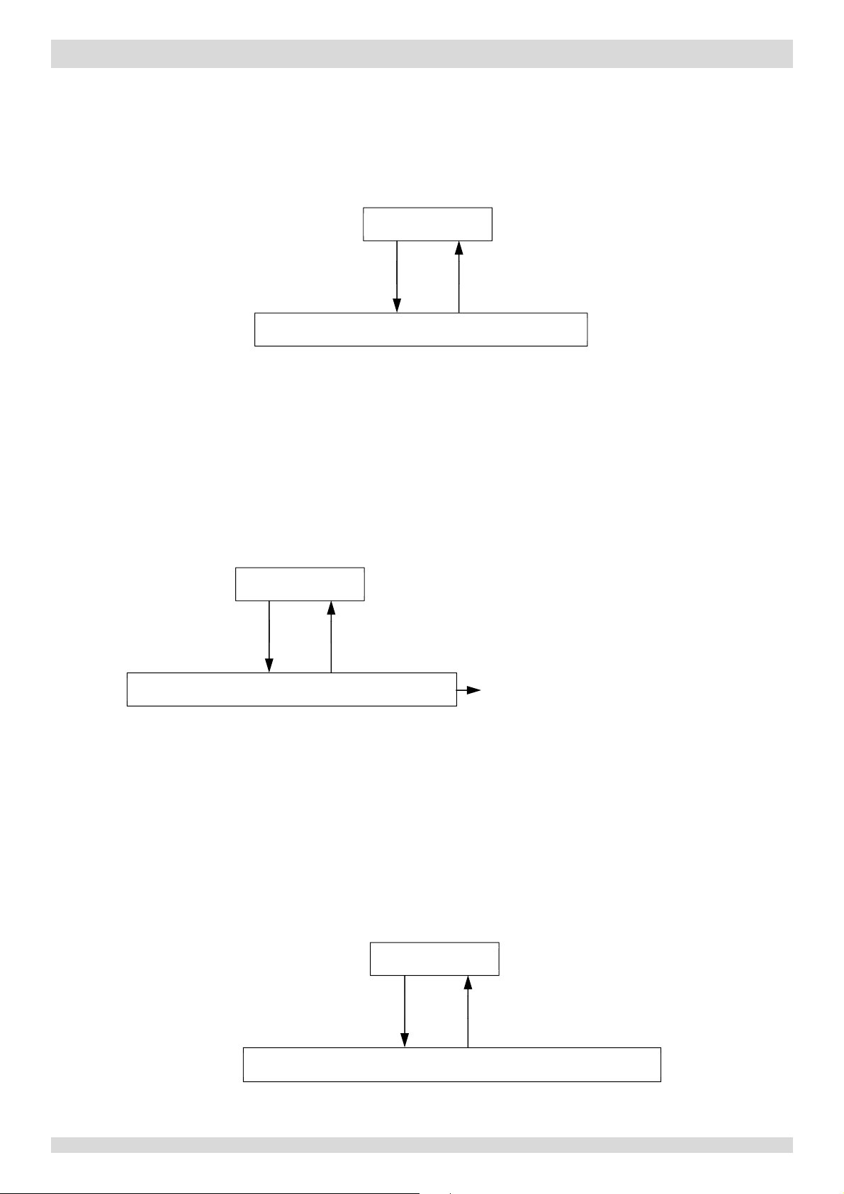
3 Refrigerant Flow Diagrams
Figure 2-3.1: Refrigerant flow during heating or domestic hot water operation
Figure 2-3.2: Refrigerant flow during cooling and defrosting operations
Heating and domestic hot water operation
MUNDOCLIMA AEROTHERM V17 - BIBLOC
Cooling and defrosting operation
12 201703

Part 3 - Control
MUNDOCLIMA AEROTHERM V17 - BIBLOC
Part 3
Control
1 Stop Operation ........................................................................................ 14
2 Standby Control ....................................................................................... 14
3 Startup Control ........................................................................................ 15
4 Normal Operation Control ....................................................................... 17
5 Protection Control ................................................................................... 19
6 Special Control ......................................................................................... 22
7 Role of Temperature Sensors in Control Functions ................................... 24
201703 13

MUNDOCLIMA AEROTHERM V17 - BIBLOC
1 Stop Operation
The stop operation occurs for one of the following reasons:
1. Abnormal shutdown: in order to protect the compressors, if an abnormal state occurs the system makes a 'stop with
thermo off’ operation and an error code is displayed on the outdoor unit PCB digital displays and on the user
interface.
2. The system stops when the set temperature has been reached.
2 Standby Control
2.1 Crankcase Heater Control
The crankcase heater is used to prevent refrigerant from mixing with compressor oil when the compressors are stopped.
The crankcase heater is controlled according to outdoor ambient temperature and the compressor on/off state. When the
outdoor ambient temperature is above 8°C or the compressor is running, the crankcase heater is off; when the outdoor
ambient temperature is at or below 8°C and either the compressor has been stopped for more than 3 hours or the unit has
just been powered-on (either manually or when the power has returned following a power outage), the crankcase heater
turns on.
2.2 Water Pump Control
When the outdoor unit is in standby, the internal and external circulator pumps run continuously.
14 201703
Part 3 - Control
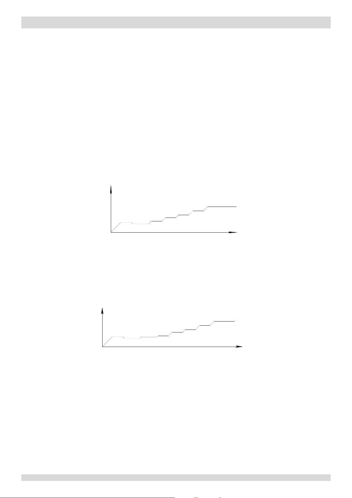
Figure 3-4.1: Compressor startup program
1,2
when ambient temperature is above 4°C
Notes:
stages in a
Figure 3-4.2:
compressor startup program1 when ambient temperature is at or below 4°C
Notes:
stages in a
step-by-step fashion and exits when the target rotation speed has been reached.
MUNDOCLIMA AEROTHERM V17 - BIBLOC
3 Startup Control
3.1 Compressor Startup Delay Control
In initial startup control and in restart control (except in oil return operation and defrosting operation), compressor startup
is delayed such that a minimum of the set re-start delay time has elapsed since the compressor stopped, in order to
prevent frequent compressor on/off and to equalize the pressure within the refrigerant system. The compressor re-start
delays for cooling and heating modes are set on the user interface. Refer to the M-Thermal Split Engineering Data Book
Part 3, 8.5 “COOL MODE SETTING Menu” and Part 3, 8.6 “HEAT MODE SETTING Menu”.
3.2 Compressor Startup Program
In initial startup control and in re-start control, compressor startup is controlled according to outdoor ambient
temperature. Compressor startup follows one of two startup programs until the target rotation speed is reached. Refer to
Figures 3-4.1, 3-4.2 and 3-4.3.
Compressor rotation
speed (rps)
Targ
82rps
40s
et rotation speed
Target rotation
Time (s
speed
Time (
)
s)
86rps
66rps
32rps
60s
36rps
90s
42rps
40s
42rps
60s
40s
56rps
40s
38rps
40s
1. Once the first, 40-second stage of the program is complete, the program proceeds to the subsequent
step-by-step fashion and exits when the target rotation speed has been reached.
2. This program is used on all M-Thermal Split models: 4kW to 16kW, single phase and three phase.
Models 4 to 8kW
Compressor rotation
speed (rps)
38rps
32rps
40s
90s
0
56rps
40s
40s
66rps
40s
1. Once the first, 40-second stage of the program is complete, the program proceeds to the subsequent
201703 15
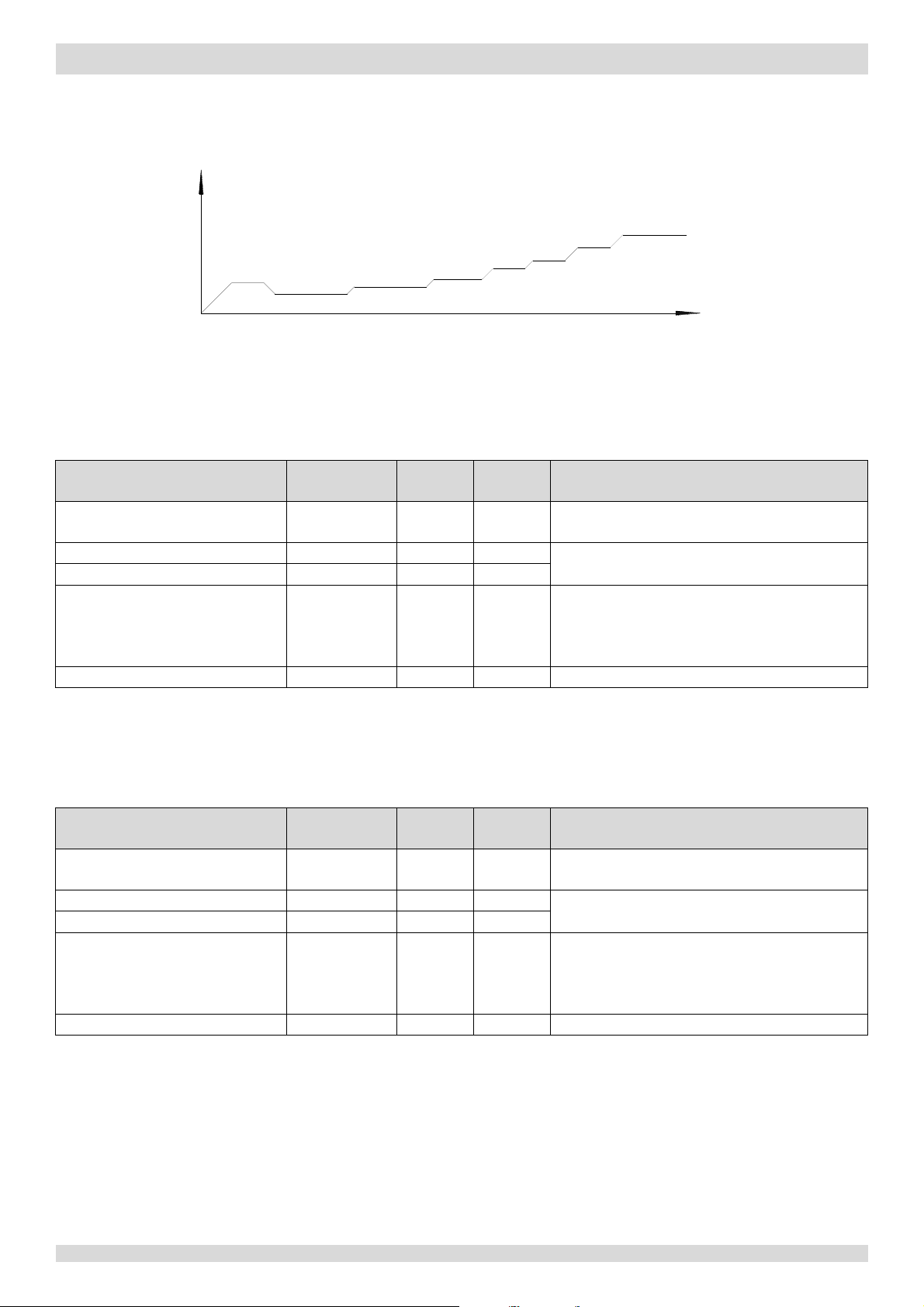
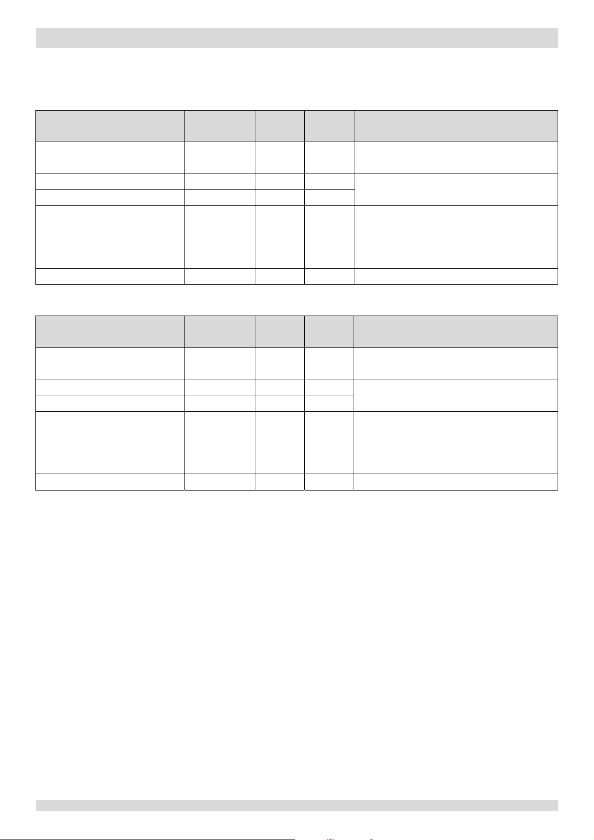
Figure 3-4.3:
compressor startup program1 when
ambient
Notes:
second stage of the program is complete, the program proceeds to the
stages in a
step-by-step fashion and exits when the target rotation speed has been reached.
I
C
to
ambient
temperature1
DC fan motor / Upper DC fan motor
Fan
Lower DC fan motor
E
Position (steps) from 0 (fully closed) to 480 (fully
open),
outdoor ambient
temperature, discharge temperature and suction
superheat
Four-way valve
ST
On
Notes:
2. Refer to
Table 3
-5.3 in Part 3, 5.6 “Outdoor Fan Control”.
Wiring diagram
l
abel
I
Compressor startup program selected
to
ambient
temperature1
DC fan motor / Upper DC fan motor
FAN1 / FAN_UP
Fan
Lower DC fan motor
FAN_DOWN
E
Position (steps) from 0 (fully
closed) to 480 (fully
open), controlled according to
outdoor ambient
temperature, discharge temperature and
suction
superheat
Four-way valve
ST
Off
Notes:
2. Refer to Table 3-5.3 in Part 3, 5.6 “Outdoor Fan Control”.
Models 10 to 16kW
temperature is at or below 4°C
Compressor rotation
speed (rps)
MUNDOCLIMA AEROTHERM V17 - BIBLOC
66rps
60s
56rps
40s
40s
38rps
40s
1. Once the first, 40-
24rps
90s
33rps
90s
42rps
3.3 Startup Control for Heating and Domestic Hot Water Operation
Table 3-4.1: Component control during startup in heating and domestic hot water modes
Component
nverter compressor COMP ƽ ƽ
lectronic expansion valve EXV ƽ ƽ
Wiring diagram
label
4-8kW 10-16kW
FAN1 / FAN_UP ƽ ƽ
FAN_DOWN ƽ
Target rotation sp
82rps
40s
eed
Time (s)
subsequent
Control functions and states
ompressor startup program selected according
run at maximum speed2
controlled according to
ƽ ƽ
1. Refer to Figure 3-4.1, Figure 3-4.2 and Figure 3-4.3 in Part 3, 4.2 “Compressor Startup Program”.
3.4 Startup Control for Cooling Operation
Table 3-4.2: Component control during startup in cooling mode
Component
nverter compressor COMP ƽ ƽ
lectronic expansion valve EXV ƽ ƽ
1. Refer to Figure 3-4.1, Figure 3-4.2 and Figure 3-4.3 in Part 3, 4.2 “Compressor Startup Program”.
4-8kW
ƽ ƽ
ƽ
ƽ ƽ
10-16kW
Control functions and states
according
run at maximum speed2
16 201703
Part 3 - Control
Wiring diagram
I
Controlled
from
hydronic system
DC fan motor / Upper DC fan motor
FAN1 / FAN_UP
Controlled
outdoor heat exchanger
pipe temperature
Lower DC fan motor
FAN_DOWN
E
Position (steps) from 0 (fully closed) to 480 (fully
open)
discharge
temperature
, suction superheat and compressor
speed
F
O
I
ƽ
Controlled
from
hydronic system
DC fan motor / Upper DC fan motor
FAN1 / FAN_UP
Controlled according to outdoor heat exchanger pipe
temperature
Lower DC fan motor
FAN_DOWN
E
Position (steps) from 0 (fully closed) to 480 (fully
open)
according to discharge
temperature
and compressor
speed
F
O
4 Normal Operation Control
4.1 Component Control during Normal Operation
Table 3-5.1: Component control during heating and domestic hot water operations
MUNDOCLIMA AEROTHERM V17 - BIBLOC
Component
nverter compressor
label
COMP
lectronic expansion valve EXV
our-way valve ST
Table 3-5.2: Component control during cooling operation
Component
nverter compressor
Wiring diagram
label
COMP
4-8kW
ƽ ƽ
ƽ ƽ
ƽ ƽ
ƽ ƽ
10-16kW
ƽ
4-8kW 10-16kW
ƽ
ƽ ƽ
ƽ
Control functions and states
according to load requirement
according to
, controlled according to
n
Control functions and states
according to load requirement
lectronic expansion valve EXV
ƽ ƽ
, controlled
, suction superheat
our-way valve ST
ƽ ƽ
ff
4.2 Compressor Output Control
The compressor rotation speed is controlled according to the load requirement. Before compressor startup, the
M-Thermal Split outdoor unit determines the compressor target speed according to outdoor ambient temperature, leaving
water set temperature and actual leaving water temperature and then runs the appropriate compressor startup program.
Refer to Part 3, 4.2 “Compressor Startup Program”. Once the startup program is complete, the compressor runs at the
target rotation speed.
During operation the compressor speed is controlled according to the rate of change in water temperature, the refrigerant
system pressure and the refrigerant temperature.
4.3 Compressor Step Control
The running speed of four-pole compressors (used on 5-7kW models) in rotations per second (rps) is half the frequency (in
Hz) of the electrical input to the compressor motor. The running speed of six-pole compressors (used on all other models)
in rotations per second (rps) is one third of the frequency (in Hz) of the electrical input to the compressor motor. The
frequency of the electrical input to the compressor motors can be altered at a rate of 1Hz per second.
201703 17
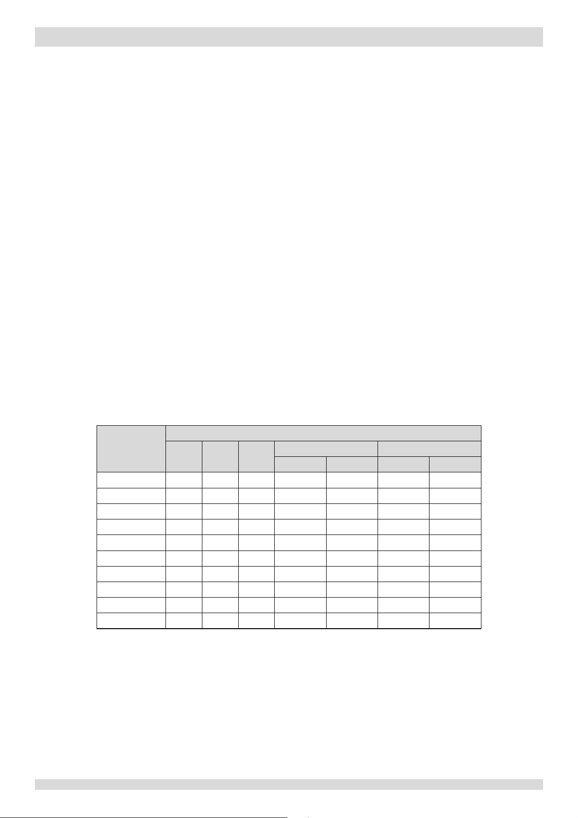
Table 3-5.3: Outdoor fan speed steps
Fan speed index
Upper fan1
Lower fan2
Upper fan1
Lower fan2
600
Notes:
Engineering Data Book
Engineering Data Book
Part 2, 4 “Wiring diagram”.
MUNDOCLIMA AEROTHERM V17 - BIBLOC
4.4 Four way Valve Control
The four-way valve is used to change the direction of refrigerant flow through the water side heat exchanger in order to
switch between cooling and heating/DHW operations. Refer to Figures 2-3.1 and 2-3.2 in Part 2, 3 “Refrigerant Flow
Diagrams”.
During heating and DHW operations, the four-way valve is on; during cooling and defrosting operations, the four-way
valve is off.
4.5 Electronic Expansion Valve Control
The position of the electronic expansion valve (EXV) is controlled in steps from 0 (fully closed) to 480 (fully open).
At power-on:
y The EXV first closes fully, then moves to the standby position (304 (steps)). After 30 seconds the EXV moves to an
initial running position, which is determined according to operating mode and outdoor ambient temperature.
After a further 150 seconds, the EXV is controlled according to suction superheat and discharge temperature.
Once a further 6 minutes have elapsed, the EXV is then controlled according to suction superheat, discharge
temperature and compressor speed.
When the outdoor unit is in standby:
y The EXV is at position 304 (steps).
When the outdoor unit stops:
y The EXV first closes fully, then moves to the standby position (304 (steps)).
4.6 Outdoor Fan Control
The speed of the outdoor unit fan(s) is adjusted in steps, as shown in Table 3-5.3.
Fan speed (rpm)
4kW
6kW
8kW
10-16kW (1Ph) 12-16kW (3Ph)
0 0 0 0 0 0 0 0
1 300
2 340
3 400
4 450
5 520
6
7 680
8 730
9 800
1. The upper fan is labelled FAN_UP in the wiring diagram. Refer to the M-Thermal Split
Part 2, 4 “Wiring diagram”.
2. The lower fan is labelled FAN_DOWN in the wiring diagram. Refer to the M-Thermal Split
300
340
400
450
520
600
680
730
800
300
340
400
450
520
600
680
730
800
300 - 300 330 300 330 300
400 380 400 380
460 440 460 440
520 500 520 500
630 610 630 610
780 760 780 760
- - - -
- - -
-
18 201703
Part 3 - Control
Figure 3-6.1: High pressure protection control
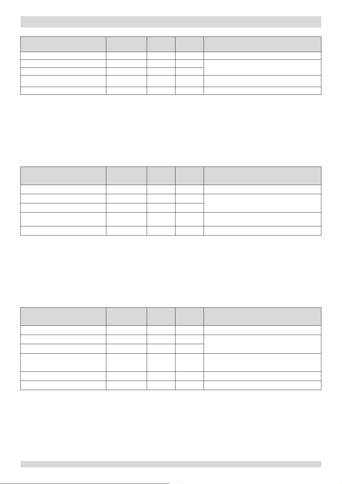
Figure 3-6.2: Low pressure protection control
Notes:
Figure 3
-6.3: High discharge temperature protection control
When P
protection occurs 3 times
in 60 minutes, the HP error is
displayed. When an H
error occurs,
a manual system restart is required
before the system can resume
operation.
MUNDOCLIMA AEROTHERM V17 - BIBLOC
5 Protection Control
5.1 High Pressure Protection Control
This control protects the refrigerant system from abnormally high pressure and protects the compressor from transient
spikes in pressure.
Normal operation
Pc > 4.4MPa Pc < 3.2MPa
High pressure protection, error code P1 is displayed
Notes:
1. P
: Discharge pressure
c
When the discharge pressure rises above 4.4MPa the system displays P1 protection and the unit stops running. When the
discharge pressure drops below 3.2MPa, the compressor enters re-start control.
5.2 Low Pressure Protection Control
This control protects the refrigerant system from abnormally low pressure and protects the compressor from transient
drops in pressure.
Normal operation
Pe < 0.14MPa
Pe > 0.30MPa
Low pressure protection, error code P0 is displayed
1. Pe: Suction pressure
0
P
When the suction pressure drops below 0.14MPa the system displays P0 protection and the unit stops running. When the
suction pressure rises above 0.3MPa, the compressor enters re-start control.
5.3 Discharge Temperature Protection Control
This control protects the compressor from abnormally high temperatures and transient spikes in temperature.
Discharge temperature > 115°C
When the discharge temperature rises above 115°C the system displays P4 protection and the unit stops running. When
201703 19
Normal operation
Discharge temperature < 90°C
High discharge temperature protection, error code P4 is displayed
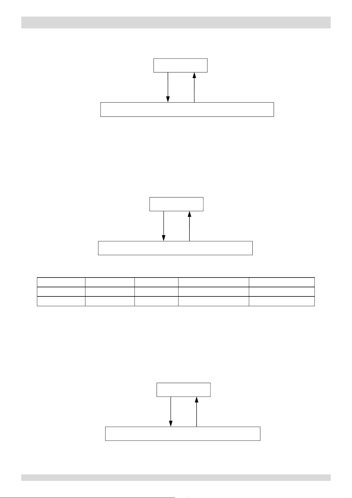
Figure 3
-6.4:Low discharge temperature protection control
Figure 3
-6.5: Compressor current protection control
Table 3
Compressor model
ATF250D22UMT
ATQ420D2UMU
Figure 3-6.4: Compressor voltage protection control
MUNDOCLIMA AEROTHERM V17 - BIBLOC
the discharge temperature drops below 90°C, the compressor enters re-start control.
Normal operation
Discharge temperature ≤ 15°C for
Discharge temperature ≥27°C
more than 5 minutes
Low discharge temperature protection, error code EA is displayed
When the discharge temperature is at or below 15°C for more than 5 minutes, the system displays EA protection and the
unit stops running. When the discharge temperature rises to 27°C or higher, the compressor enters re-start control.
5.4 Compressor Current Protection Control
This control protects the compressor from abnormally high currents.
Normal operation
Current > Current
Compressor current protection, error code P3 is displayed
Current < Current
max
max
-6.1: Current limitation for compressors
Model name
Current
max
When the compressor current rises above Current
the compressor current drops below Current
Models 4 and 6kW
SNB172FJFMC
18A 20A 31A 15A
Model 8kW
the system displays P3 protection and the unit stops running. When
max
, the compressor enters re-start control.
max
Models 10 to 16kW (1Ph) Models 10 to 16kW (3Ph)
ATQ420D1UMU
5.5 Voltage Protection Control
This control protects the M-Thermal Split from abnormally high or abnormally low voltages.
Normal operation
Voltage ≥ 265V
or Voltage ≤ 172V
Compressor voltage protection, error code H7 is displayed
256V < Voltage < 180V
When the phase voltage of AC power supply is at or above 265V for more than 30 seconds, the system displays H7
protection and the unit stops running. When the phase voltage drops below 265V for more than 30 seconds, the
20 201703

Part 3 - Control
refrigerant system restarts once the compressor re-start delay has elapsed. When the phase voltage is below 172V, the
system displays H7 protection and the unit stops running. When the AC voltage rises to more than 180V, the refrigerant
system restarts once the compressor re-start delay has elapsed.
MUNDOCLIMA AEROTHERM V17 - BIBLOC
5.6 DC Fan Motor Protection Control
This control protects the DC fan motors from strong winds and abnormal power supply. DC fan motor protection occurs
when any one of the following the following three sets of conditions are met:
Outdoor ambient temperature is at or above 4°C and actual fan speed differs from target fan speed by 200rpm or
more for more than 3 minutes.
Outdoor ambient temperature is below 4°C and actual fan speed differs from target fan speed by 300rpm or more for
more than 3 minutes.
Actual fan speed is less than 240rpm for more than 20 seconds.
When DC fan motor protection control occurs the system displays the H6 error code and the unit stops running. After 3
minutes, the unit restarts automatically. When H6 protection occurs 10 times in 120 minutes, the HH error is displayed.
When an HH error occurs, a manual system restart is required before the system can resume operation.
5.7 Water Side Heat Exchanger Anti-freeze Protection Control
This control protects the water side heat exchanger from ice formation. The water side heat exchanger electric heater is
controlled according to outdoor ambient temperature, water side heat exchanger water inlet temperature and water side
heat exchanger water outlet temperature.
In heating mode, if the outdoor temperature falls below 3°C and either the water side heat exchanger water inlet
temperature or water side heat exchanger water outlet temperature are below 25°C, the water side heat exchanger
electric heater turns on. When the outdoor ambient temperature rises above 5°C and either the water side heat exchanger
water inlet temperature or water side heat exchanger water outlet temperature are above 30°C, the water side heat
exchanger turns off.
When water side heat exchanger anti-freeze protection occurs the system displays error code Pb and the unit stops
running.
201703 21
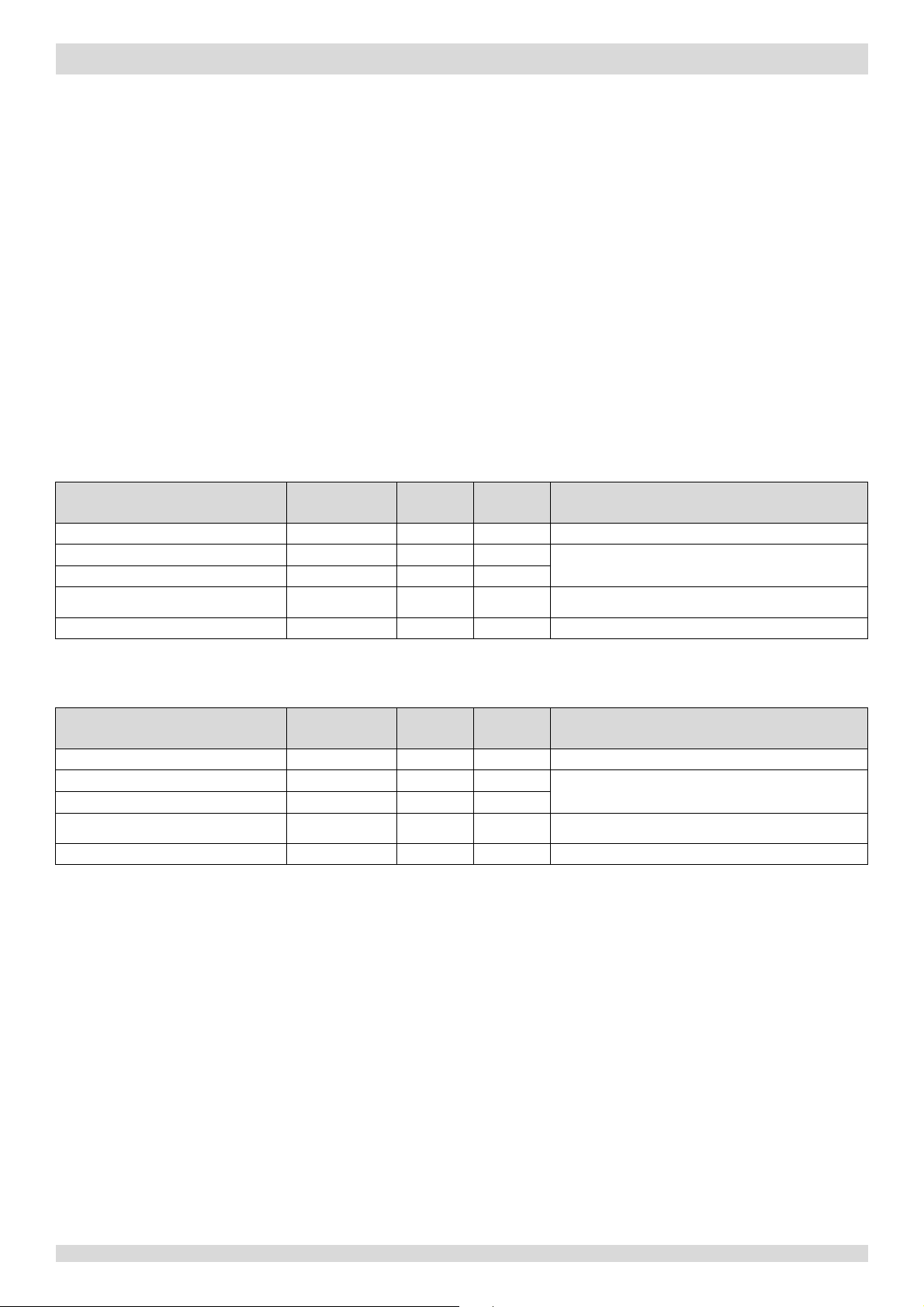
Table 3-7.1: Outdoor unit component control during oil return operation in cooling mode
Inverter compressor
Runs
at oil return operation rotation speed
DC fan motor / Upper DC fan motor
Controlled according to outdoor heat exchanger pipe
temperature
Lower DC fan motor
E
304 (steps)
Four-way valve
ST
Off
Table 3-7.2: Outdoor unit component control during oil return operation in heating and DHW modes
Wiring diagram
label
Inverter compressor
COMP
Runs
at oil return operation rotation speed
DC fan motor / Upper DC fan motor
FAN1 / FAN_UP
Controlled according to outdoor heat exchanger pipe
temperature
Lower DC fan motor
FAN_DOWN
E
ƽ
304 (steps)
Four-way valve
ST
On
MUNDOCLIMA AEROTHERM V17 - BIBLOC
6 Special Control
6.1 Oil Return Operation
In order to prevent the compressor from running out of oil, the oil return operation is conducted to recover oil that has
flowed out of the compressor and into the refrigerant piping. When the oil return operation is being conducted, the
outdoor unit refrigerant system main PCB displays code d0.
Timing of oil return operation:
When the compressor cumulative operating time with running rotation speed less than 42rps reaches 6 hours.
The oil return operation ceases when any one of the following three conditions occurs:
Oil return operation duration reaches 5 minutes.
Compressor stops.
Mode change command is received.
Tables 3-7.1 show component control during oil return operation in cooling mode.
Component
lectronic expansion valve EXV ƽ ƽ
Wiring diagram
label
COMP ƽ ƽ
FAN1 / FAN_UP ƽ ƽ
FAN_DOWN ƽ
4-8kW 10-16kW
ƽ ƽ
Control functions and states
Tables 3-7.2 show component control during oil return operation in heating and DHW modes.
Component
lectronic expansion valve EXV
4-8kW
ƽ ƽ
ƽ ƽ
ƽ
ƽ
ƽ ƽ
10-16kW
Control functions and states
6.2 Defrosting Operation
In order to recover heating capacity, the defrosting operation is conducted when the outdoor unit air side heat exchanger
is performing as a condenser. The defrosting operation is controlled according to outdoor ambient temperature, air side
heat exchanger refrigerant outlet temperature and the compressor running time.
The defrosting operation ceases when any one of the following three conditions occurs:
Defrosting operation duration reaches 10 minutes.
The air side heat exchanger refrigerant outlet temperature is above 8°C for more than 10 seconds.
The air side heat exchanger refrigerant outlet temperature is above 10°C.
22 201703
Part 3 - Control
Table 3-7.3: Component control during defrosting operation
Wiring diagram
label
Inverter compressor
COMP
Runs
at defrosting operation rotation
speed
DC fan motor / Upper DC fan motor
FAN1 / FAN_UP
Off
Lower DC fan motor
FAN_DOWN
E
F
Four-way valve
ST
Off
I
Runs at
rotation
DC fan motor / Upper DC fan motor
Runs at force cooling operation
Lower DC fan motor
E
lectronic expansion valve
304 (steps)
F
O
Wiring diagram
I
nverter compressor
COMP
Controlled
DC fan motor / Upper DC fan motor
FAN1 / FAN_UP
Controlled according to outdoor heat exchanger pipe
temperature
Lower DC fan motor
FAN_DOWN
E
Position (steps) from 0 (fully closed) to 480 (fully
open), controlled
F
O
Tank electric heater
On
MUNDOCLIMA AEROTHERM V17 - BIBLOC
Component
lectronic expansion valve EXV ƽ ƽ
4-8kW
ƽ ƽ
ƽ ƽ
ƽ
ƽ ƽ
10-16kW
Control functions and states
ully open
6.3 Force Cooling Operation
The force cooling operation helps the refrigerant recovering before removal the water side heat exchanger.
The force cool mode can be ended by pushing the button on the outdoor refrigerant system main PCB named “force-cool”
for 5s or this mode will be ended automatic if the system has operated force cool mode for more than 30 minutes.
Table 3-7.4: Component control during force cool operation
Component
nverter compressor
Wiring diagram
label
COMP
FAN1 / FAN_UP
FAN_DOWN
4-8kW 10-16kW
ƽ ƽ
ƽ ƽ
ƽ
Control functions and states
force cooling operation
speed
speed
EXV
our-way valve ST
ƽ ƽ
ƽ ƽ
ff
6.4 Fast DHW Operation
Fast DHW operation is used to quickly meet a requirement for domestic hot water when DHW priority has been set on the
user interface. Refer to the M-Thermal Split Engineering Data Book Part 3, 8.4 “DHW MODE SETTING Menu”.
Domestic hot water demand priority can be ended by changing the switch on controller from "on" to "off".
Table 3-7.5: Component control during fast DHW operation
Component
lectronic expansion valve EXV
our-way valve ST
TBH
label
4-8kW
ƽ ƽ
ƽ ƽ
ƽ ƽ
ƽ ƽ
ƽ
10-16kW
ƽ
ƽ
n
Control functions and states
according to load requirement
according to discharge superheat
201703 23

Figure 3-7.1: Location of the temperature sensors on M-Thermal Split systems
Notes:
1. The names and functions of the temperature sensors labelled 1 to 12 in
this figure are detailed in Table 3
-7.1.
7 Role of Temperature Sensors in Control Functions
MUNDOCLIMA AEROTHERM V17 - BIBLOC
24 201703
Part 3 - Control
Table 3-7.1: Names and functions of the temperature sensors
Number
Sensor
code
Discharge pipe
sensor
Electronic expansion valve control2
Discharge
super
heat control
Electronic expansion valve control2
Discharge superheat control
Outdoor a
temperature
sensor
Compressor startup control4
xpansion valve control
Crankcase heater control9
Compressor startup control4
Crankcase heater
control9
Air side
refrigerant
temperature
sensor
Electronic expansion valve control2
Outdoor fan control3
Water side heat exchanger
refrigerant inlet
temperature sensor
5
Water side heat exchanger
refrigerant outlet (gas pipe)
temperature sensor
Suction pipe
temperature
sensor
Heating
Cooling
Water side heat exchanger
water i
sensor
Tw
Water side heat exchanger
water out
sensor
Tw
_out
Heating
Cooling
DHW
Backup electric heater
o
Compressor output control5
Auto mode control
Compressor output5 and on/off control6
Auto mode control
Compressor output control5
DHW priority control11
Auxiliary heat source
water
outlet temperature sensor
Auxiliary heat source control
Compressor output control
Room
Auto mode control
Compressor output control5
Domestic hot water
temperature
Disinfection operation control
DHW priority control11
Notes:
to refrigerant flow is
refer to
5. Refer to Part 3, 4.2 “Compressor Output Control”.
10.
MUNDOCLIMA AEROTHERM V17 - BIBLOC
Sensor name1
Mode Control functions
Heating
1
2
temperature
mbient
Tp
T4
Cooling
Heating
Cooling
Outdoor fan control3
Compressor output control5
Electronic e
Defrosting operation control
7
Low pressure protection control
Compressor output control5
Electronic expansion valve control
Outdoor fan control
3
2
7
2
heat exchanger
3
outlet
T3
Heating
Cooling
Defrosting operation control7
Compressor output control
Outdoor fan control
5
3
Heating
4
(liquid pipe)
T2B
Compressor output control5
DHW
6
7
8
9
10
11
12
nlet temperature
utlet temperature sensor
temperature sensor Ta
let temperature
water
tank
sensor
T2 Heating Freeze prevention control10
Th
Electronic expansion valve control2
Heating
_in
Freeze prevention control
Cooling
Compressor output5 and on/off control6
Freeze prevention control
Backup electric heater control
DHW priority control11
Backup electric heater control
T1
Heating
Cooling
DHW
T1B Heating
Heating
Cooling
Climate related curve
DHW tank immersion heater control
Backup electric heater control
T5 DHW
Auxiliary heat source control
Solar energy kit control
Compressor output control5
10
10
5
1. Sensor names in this service manual referring
named according refrigerant flow during cooling operation
Part 2, 3 “Refrigerant Flow Diagrams”.
2. Refer to Part 3, 4.5 “Electronic Expansion Valve Control”.
3. Refer to Part 3, 4.6 “Outdoor Fan Control”.
4. Refer to Part 3, 3 “Startup Control”.
201703 25
6. Refer to Part 3, 1 “Stop Operation”.
7. Refer to Part 3, 6.2 “Defrosting Operation”.
8. Refer to Part 3, 5.2 “Low Pressure Protection Control”.
9. Refer to Part 3, 2.1 “Crankcase Heater Control”.
Refer to Part 3, 2.2 “Freeze Prevention Control”.
11. Refer to Part 3, 6.4 “Fast DHW Operation”.

MUNDOCLIMA AEROTHERM V17 - BIBLOC
26 201703

Part 4 - Diagnosis and Troubleshooting
MUNDOCLIMA AEROTHERM V17 - BIBLOC
Part 4
Diagnosis and
Troubleshooting
1 Electric Control Box Layout ....................................................................... 28
2 PCBs ......................................................................................................... 31
3 Error Code Table ....................................................................................... 45
4 Troubleshooting ....................................................................................... 47
5 Appendix to Part 4 ................................................................................... 98
201703 27
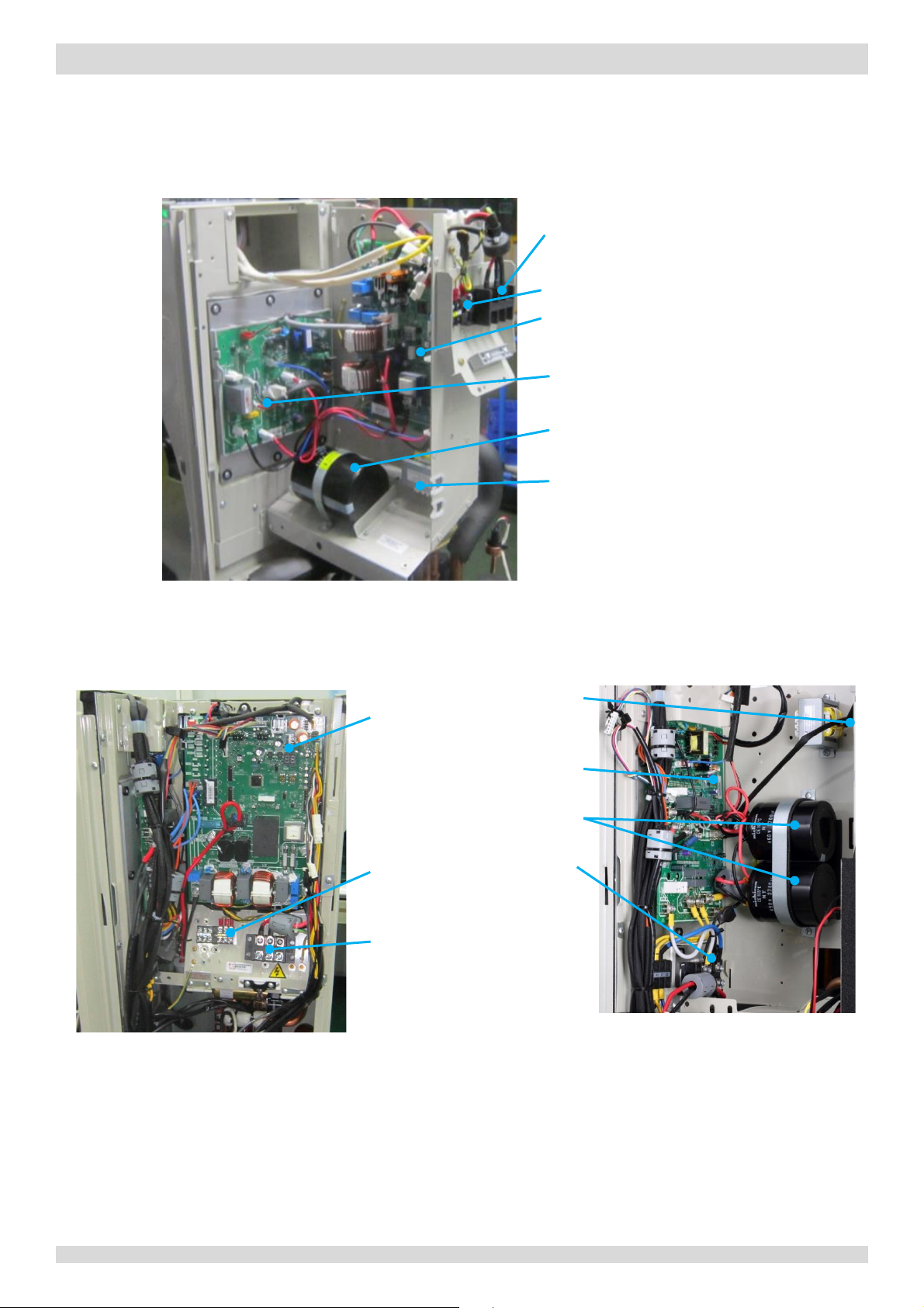
1 Electric Control Box Layout
Figure 4-1.1:
electric control box
P
Communication terminal blocks
M
Inverter module
C
Transfor
Figure
Figure 4-1.3:
side view
Transformer
M
module
ors
Communication
terminal blocks
ridge rectifier
Power supply
terminals
1.1 Outdoor Unit Electric Control Box Layout
Models 4 to 8kW
MUNDOCLIMA AEROTHERM V17 - BIBLOC
ower supply terminals
ain PCB
apacitor
mer
Models 10 to 16kW (1Ph)
4-1.2:
electric control box
ain PCB
Inverter
electric control box
Capacit
B
28 201703
 Loading...