


English
CL20390 to CL20391
www.mundoclima.com
Service manual
FLOOR STANDING
MUCO-H6T

Service Manual
Table of Contents
Part
Ⅰ
: T
echnical Information
.......................................................................... 4
1. Summary
......................................................................................................................... 4
2. Specications
............................................................................................................. 5
2.1 Specication Sheet ...
...........................................................................................................
5
2.2 Capacity Curve in Dif
ferent Outdoor
Temperature
.............................................................. 9
2.3 Cooling and Heating Data Sheet in Rated Frequency ........................................................ 9
3. Outline Dimension Diagram
..........................................................................10
3.1 Indoor Unit ...
.......................................................................................................................
10
3.2 Outdoor Unit .......................................................................................................................11
4. Refrigerant System Diagram
....................................................................... 12
5. Electrical Part
............................................................................................................ 13
5.1 Wiring Diagram ...
...............................................................................................................
13
5.2 PCB Printed Diagram ........................................................................................................ 17
6. Function and Control
......................................................................................... 19
6.1 Instructions of Control Buttons on Indoor Panel ...
.............................................................
19
6.2 Remote Controller Introduction ......................................................................................... 23
6.3 Introduction of Each Mode Function ...
...............................................................................
27
Part
Ⅱ
: Installation and Maintenance
.................................................... 35
7. Notes for Installation and Maintenance
............................................. 35
8. Installation
................................................................................................................... 37
8.1 Installation Dimension Diagram ...
......................................................................................
37
8.2 Installation Procedures ...
...................................................................................................
38
8.3 Installation Parts-Checking ...
............................................................................................
39
8.4 Selection of Installation Location ...
....................................................................................
39
8.5 Electric Connection Requirement ...
...................................................................................
39
8.6 Installation of Indoor Unit ...
................................................................................................
39
8.7 Installation of Outdoor Unit ...
.............................................................................................
41
8.8 V
acuum Pumping and Leak Detection
.............................................................................. 43
8.9 Check after Installation and
T
est Operation
...................................................................... 43

Service Manual
9. Maintenance
.............................................................................................................. 44
9.1 Error Code ........................................................................................................................ 44
9.2 Procedure of T
roubleshooting
.......................................................................................... 46
9.3 Maintenance Method for Normal Malfunction ................................................................... 50
10. Exploded View and Parts List
................................................................ 52
10.1 Indoor Unit ...................................................................................................................... 52
10.2 Outdoor Unit ................................................................................................................... 55
11. Removal Procedure
......................................................................................... 59
11.1 Removal Procedure of Indoor Unit ................................................................................. 59
11.2 Removal Procedure of Outdoor Unit .............................................................................. 66
Appendix:
.......................................................................................................................... 78
Appendix 1: Reference Sheet of Celsius and Fahrenheit ...................................................... 78
Appendix 2: Conguration of Connection Pipe ....................................................................... 78
Appendix 3: Pipe Expanding Method ..................................................................................... 79
Appendix 4: List of Resistance for T
emperature Sensor
........................................................ 80

Service Manual
1. Summary
Part
Ⅰ
: Technical Information
Indoor Unit:
Outdoor Unit:
Remote Controller:
YB1F2(XFAN)
FAN
AUTO
OPER
HEALTH
AIR
FILTER
TURBO
ON/OFF
X-FAN
HOUR
HUMIDITY
ON/OFF
MODE
FAN
X-FAN
TURBO
TEMP
TIMER
SLEEP
LIGHT
(CL96462)
MUCO-48-H6T
MUCO-60-H6T
MUCO-60-H6T
MUCO-48-H6T
4

Service Manual
2. Specications
2.1 Specication Sheet
Model
Product Code
Power
Supply
Rated V
oltage V~ 380-415
Rated Frequency Hz 50
Phases 3
Power Supply Mode Outdoor
Cooling Capacity W 12310
Heating Capacity W 12310
Cooling Power Input W 4900
Heating Power Input W 4400
Cooling Power Current A 9
Heating Power Current A 9
Rated Input W 6400
Rated Current A 13
Air Flow Volume(SH/H/M/L/SL) m
3
/h 1950/1900/1700/1530/-
Dehumidifying Volume L/h 5
EER W/W 2.51
COP W/W 2.80
SEER W/W /
HSPF W/W /
Application
Area m
2
55-85
Indoor Unit
Model of indoor unit
Indoor Unit Product Code
Fan Type Centrifugal
Diameter Length(DXL) mm Φ379X180.5
Fan Motor Cooling Speed(SH/H/M/L/SL) r/min 620/585/500/460/-
Fan Motor Heating Speed(SH/H/M/L/SL) r/min 620/585/500/460/-
Output of Fan Motor W 180
Fan Motor RLA A 1.5
Fan Motor Capacitor μF /
Input of Heater W /
Evaporator Form Aluminum Fin-copper
Tube
Pipe Diameter mm Φ7
Row-n Gap mm 2-1.4
Coil Length (LXDXW) mm 876.3X25.4X472
Swing Motor Model MP35AK/MP35AB
Output of Swing Motor W 2
Fuse A 5
Sound Pressure Level (SH/H/M/L/SL) dB (A) 55/53/49/45/-
Sound Power Level (SH/H/M/L/SL) dB (A) 65/63/59/55/-
Dimension (WXHXD) mm 581X1870X395
Dimension of Carton Box (LXWXH) mm 2080X735X530
Dimension of Package (LXWXH) mm 2083X738X545
Net Weight kg 58
Gross Weight kg 84
MUCO-48-H6T
CL20390
MUCO-48-H6T
UI20390
5

Service Manual
The above data is subject to change without notice; please refer to the nameplate of the unit.
Outdoor Unit
Model of Outdoor Unit
Outdoor Unit Product Code
Compressor Manufacturer/T
rademark Dalian SANYO Compressor Co.;Ltd.
Compressor Model C-SBP160H38C
Compressor Oil FV68S
Compressor T
ype Scroll
L.R.A. A 66
Compressor RLA A 7.58
Compressor Power Input W 4300
Overload Protector 37HM536-15
Throttling Method Capillary
Operation Temp
o
C 16~30
Ambient T
emp
(Cooling)
o
C 18~43
Ambient Temp (Heating)
o
C -7~24
Condenser Form Aluminum Fin-copper
Tube
Pipe Diameter mm Ф9.52
Rows-n Gap mm 2-1.4
Coil Length (LXDXW) mm 975X44X813
Fan Motor Speed rpm 850
Output of Fan Motor W 82
Fan Motor RLA
A 0.81
Fan Motor Capacitor μF 3.5
Air Flow Volume of Outdoor Unit m
3
/h 3600
Fan Type Axial-ow
Fan Diameter mm Ф480
Defrosting Method Automatic Defrosting
Climate T
ype T1
Isolation I
Moisture Protection IPX4
Permissible Excessive Operating Pressure for the
Discharge Side
MPa 4.3
Permissible Excessive Operating Pressure for the
Suction Side
MPa 2.5
Sound Pressure Level (H/M/L) dB (A) 59/-/-
Sound Power Level (H/M/L) dB (A) 69/-/-
Dimension (WXHXD) mm 840X1018X412
Dimension of Carton Box (LXWXH) mm 1100X450X880
Dimension of Package (LXWXH) mm 1103X453X1010
Net Weight kg 90
Gross Weight kg 100
Refrigerant R410A
Refrigerant Charge kg 3.1
Connection
Pipe
Length m 5
Gas Additional Charge g/m 100
Outer Diameter Liquid Pipe mm Ф12
Outer Diameter Gas Pipe mm Ф19
Max Distance Height m 20
Max Distance Length m 30
Note: The connection pipe applies metric diameter.
MUCO-48-H6T
UE20390
6

Service Manual
Model
Product Code
Power
Supply
Rated Voltage V~ 380-415
Rated Frequency Hz 50
Phases 3
Power Supply Mode Outdoor
Cooling Capacity W 15000
Heating Capacity W 17500
Cooling Power Input W 6000
Heating Power Input W 5850
Cooling Power Current A 9.61
Heating Power Current A 9.6
Rated Input W 8000(10500)
Rated Current A 13
Air Flow Volume(SH/H/M/L/SL) m
3
/h 2000
Dehumidifying Volume L/h 5.5
EER W/W 2.5
COP W/W 2.99
SEER W/W /
HSPF W/W /
Application
Area m
2
80-100
Indoor Unit
Model of indoor unit
Indoor Unit Product Code
Fan Type Centrifugal
Diameter Length(DXL) mm Ф379X180.5
Fan Motor Cooling Speed(SH/H/M/L/SL) r/min 620/585/500/460/-
Fan Motor Heating Speed(SH/H/M/L/SL) r/min 620/585/500/460/-
Output of Fan Motor W 180
Fan Motor RLA A /
Fan Motor Capacitor μF /
Input of Heater W 2500
Evaporator Form Aluminum Fin-copper
Tube
Pipe Diameter mm Ф7.94
Row-n Gap mm 3-1.5
Coil Length (LXDXW) mm 836X62X472
Swing Motor Model MP35AK
Output of Swing Motor W 4
Fuse A 5
Sound Pressure Level (SH/H/M/L/SL) dB (A) 52/50/46/44/-
Sound Power Level (SH/H/M/L/SL) dB (A) 62/60/56/54/-
Dimension (WXHXD) mm 581X1870X395
Dimension of Carton Box (LXWXH) mm 2080X735X530
Dimension of Package (LXWXH) mm 2083X738X545
Net Weight kg 61
Gross Weight kg 87
MUCO-60-H6T
CL20391
MUCO-60-H6T
UI20391
7

Service Manual
The above data is subject to change without notice; please refer to the nameplate of the unit.
Outdoor Unit
Model of Outdoor Unit
Outdoor Unit Product Code
Compressor Manufacturer/T
rademark Dalian SANYO Compressor Co.; Ltd.
Compressor Model C-SBP185H38A
Compressor Oil FV68S
Compressor
T
ype Scroll
L.R.A. A /
Compressor RLA A 9.31
Compressor Power Input W 5200
Overload Protector UP18RA052-550
Throttling Method Capillary
Operation Temp
o
C 16~30
Ambient T
emp
(Cooling)
o
C 18~43
Ambient Temp (Heating)
o
C -7~24
Condenser Form Aluminum Fin-copper
Tube
Pipe Diameter mm Ф9.52
Rows-n Gap mm 2-1.4
Coil Length (LXDXW) mm 975X44X813
Fan Motor Speed rpm 830
Output of Fan Motor W 68
Fan Motor RLA
A 0.8
Fan Motor Capacitor μF 3.5
Air Flow Volume of Outdoor Unit m
3
/h 3600
Fan Type Axial-ow
Fan Diameter mm Ф472
Defrosting Method Automatic Defrosting
Climate T
ype T1
Isolation I
Moisture Protection IPX4
Permissible Excessive Operating Pressure for the
Discharge Side
MPa 4.3
Permissible Excessive Operating Pressure for the
Suction Side
MPa 2.5
Sound Pressure Level (H/M/L) dB (A) 62/-/-
Sound Power Level (H/M/L) dB (A) 72/-/-
Dimension (WXHXD) mm 1032X1250X412
Dimension of Carton Box (LXWXH) mm 1100X450X1280
Dimension of Package (LXWXH) mm 1103X453X1295
Net Weight kg 114
Gross Weight kg 125
Refrigerant R410A
Refrigerant Charge kg 4.3
Connection
Pipe
Length m 5
Gas Additional Charge g/m 100
Outer Diameter Liquid Pipe mm Ф12
Outer Diameter Gas Pipe mm Ф19
Max Distance Height m 20
Max Distance Length m 30
Note: The connection pipe applies metric diameter.
MUCO-60-H6T
UE20391
8
Service Manual
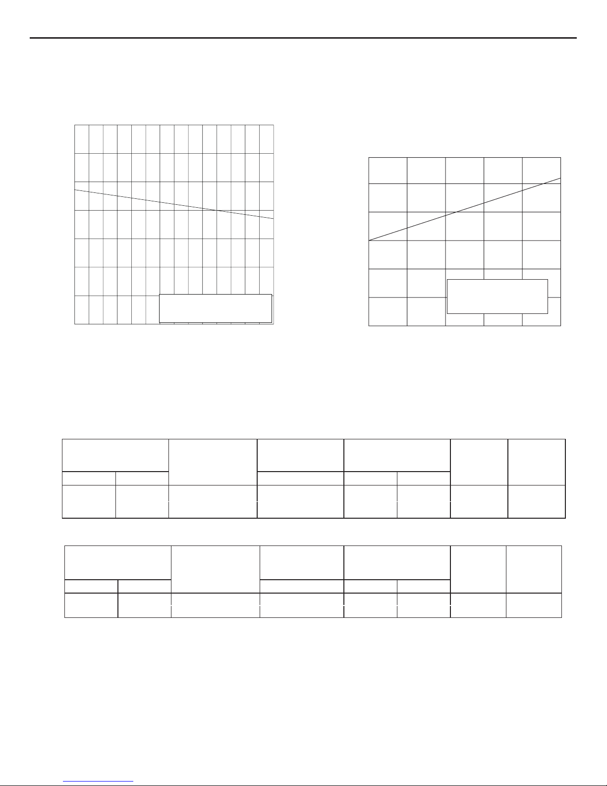
2.2 Capacity Curve in Different Outdoor Temperature
Cooling:
Heating:
2.3 Cooling and Heating Data Sheet in Rated Frequency
Rated cooling condition(°C)
(DB/WB)
Model
Pressure of gas pipe
connecting indoor and
outdoor unit
Inlet and outlet pipe
temperature of heat
exchanger
Fan speed of
indoor unit
Fan speed of
outdoor unit
Indoor Outdoor P
(MPa) T1 (°C)
T2 (°C)
27/19 35/24
48/60K
0.8~1.0 8.0~12
43~39
Super High High
Rated heating condition(°C)
(DB/WB)
Model
Pressure of gas pipe
connecting indoor
and outdoor unit
Inlet and outlet pipe
temperature of heat
exchanger
Fan speed of
indoor unit
Fan speed of
outdoor unit
Indoor Outdoor P (MPa) T1 (°C)
T2 (°C)
20/- 7/6
48/60K
1.7~1.8
44~42 -4~3
Super High High
Cooling:
Heating:
Instruction:
T1: Inlet and outlet pipe temperature of evaporator
T2: Inlet and outlet pipe temperature of condenser
P: Pressure at the side of big valve
Connection pipe length: 5m.
50
60
70
80
90
100
110
120
32 33 34 35 36 37 38 39 40 41 42 43 44 45 46
Outdoor temp.( )
Capacity ratio (%)
ConditionIndoor: DB27 ,WB19;
Indoor air flow: Super High Pipe
length: 5m.
0
-7 -5 -3 0 510
20
40
60
80
100
120
Outdoor Temp.(
)
Capacity ratio(%)
ConditionIndoor: DB20 ;
Indoor air flow: Super High Pipe
length: 5m.
°C °C
°C
°C
°C
9

Service Manual
3. Outline Dimension Diagram
3.1 Indoor Unit
1870
518
395
Unit:mm
MUCO-48-H6T
MUCO-60-H6T
10

Service Manual
3.2 Outdoor Unit
950
572
1250
412
1032
340
378
Unit:mm
Unit:mm
840
340
1018412
950
378
572
MUCO-48-H6T
MUCO-60-H6T
11

Service Manual
4. Refrigerant System Diagram
Connection pipe specication:
Liquid pipe:1/2" (12mm) Gas pipe:3/4" (19mm)
Indoor unit
Outdoor unit
COOLING
HEATING
4-Way valve
Discharge
Suction
Heat
exchanger
(evaporator)
Heat
exchanger
(condenser)
Valve
Valve
Liquid pipe
side
Gas pipe
side
Accumlator
Compressor
Strainer Strainer
Capillary
12

Service Manual
Symbol Symbol Color Symbol Symbol Color Symbol Name
WH White GN Green S AT OVERLOAD
YE Y
ellow BN Brown COMP Compressor
RD Red BU Blue Grounding wire
YEGN Yellow/Green BK Black C1 CBB65
VT Violet OG Orange C2 CBB61
5. Electrical Part
5.1 Wiring Diagram
● Instruction
●
Indoor Unit
600007000276
$335,17('&,5&8,7%2$5'
57
&211(&725
;
&1
57
$35(&(,9(5$1'',63/$<%2$5'
0
&1
&1
0
&1 &1
1&1&
75$16)250(5
7(50,1$/
%/2&.
Ė
ė
Ę
ę
3(
0
/
0$*1(7,&
5,1*
3(
3(
3(
&211(&725
287'22581,7
%8
%1
2+($7 ,+($7
.0
,+($72+($7
2+($7 ,+($7
%.
97
97
%8
/
;7
$&/
1
%1
1
/
/
%.
;
<(
2*
:+
<(*1
97
%.
%1
29&
/33
2)$1
:$<
&203
67(33,1*02725
83'2:1
/()75,*+7
67(33,1*02725
;
&211(&725
&1
%8
<(
:+
5'
6(1625
6(1625
52207(03
3,3(7(03
;
&1
&1
+($57(5
)87
)87
5'
%8
(+
(+
(+
5'
%8
6$7
6$7
5'
%8
%8
5'
%.
)$1
1287
/287
5'
%8
,)$1
1
&1
$3
<(*1
%.
5'
)$1
&1
&211(&725
;
<(*1
02725
%1
%8
.0
.0
δ9ε
MUCO-48-H6T
13

Service Manual
MUCO-60-H6T
600007000276
$335,17('&,5&8,7%2$5'
57
&211(&725
;
&1
57
$35(&(,9(5$1'',63/$<%2$5'
0
&1
&1
0
&1 &1
1&1&
75$16)250(5
7(50,1$/
%/2&.
Ė
ė
Ę
ę
3(
0
/
0$*1(7,&
5,1*
3(
3(
3(
&211(&725
287'22581,7
%8
%1
2+($7 ,+($7
.0
,+($72+($7
2+($7 ,+($7
%.
97
97
%8
/
;7
$&/
1
%1
1
/
/
%.
;
<(
2*
:+
<(*1
97
%.
%1
29&
/33
2)$1
:$<
&203
67(33,1*02725
83'2:1
/()75,*+7
67(33,1*02725
;
&211(&725
&1
%8
<(
:+
5'
6(1625
6(1625
52207(03
3,3(7(03
;
&1
&1
+($57(5
)87
)87
5'
%8
(+
(+
(+
5'
%8
6$7
6$7
5'
%8
%8
5'
%.
)$1
1287
/287
5'
%8
,)$1
1
&1
$3
<(*1
%.
5'
)$1
&1
&211(&725
;
<(*1
02725
%1
%8
.0
.0
δ9ε
14

Service Manual
Indoor unit
Outdoor unit
Accumlator
Discharge
Suction
Heat
exchanger
(evaporator)
Valve
Valve
Liquid pipe
side
Gas pipe
side
Compressor
Strainer
Capillary
Heat
exchanger
(condenser)
These wiring diagrams are subject to change without notice; please refer to the one supplied with the unit.
● Outdoor Unit
MUCO-48-H6T
32:(5
;7
<(*1
%8
97
%.
%1
1
/
/
/
/
/
/
1
7(50,1$/
;7
/$
1%
7
7
$&&217$&725
.%1%97
7
7
7
&203
&855(17
3527(&725
)$
97
%.
%1
.0
$
$
:
9
8
(
7
6
5
3+$6(
$
&
3527(&725
<(*1
%.
%1
%8
/
/
/
)$102725
3(
<(*1
0
%1
&$3
&
5' %8
%.
;
5(9(56(
29(5
;7
+,*+35(6685(
6:,7&+
<(*1
,1'22581,7
&211(&725
&211(&725
%/2&.
7(50,1$/
%/2&.
%1
%1
97
8%8%
%8
:+
%8
%8
3(
5($&725
/
<9
3
/2:35(6685(
6:,7&+
1
97
3(
3(
(+
%$1'+($7(5
&2035(6625
9$/9(
:$<
%8
%.97%8
%1
%1
;7
)87
%.
&203
/36
7(50,1$/
%/2&.
:+
<(
97
2*
%.
%8
7(50,1$/
%/2&.
7(03
',6&+$5*(
7(037(03
57
78%( 5220
;
57
;
57
;
6(1625 6(1625 6(1625
;
%.
:+
5'
:+
:+
:+
5'
%8
<(
3
+36
%.
/
/
0$*1(7,&
5,1*
0$*1(7,&
5,1*
600007000274
15

Service Manual
These wiring diagrams are subject to change without notice; please refer to the one supplied with the unit.
32:(5
;7
<(*1
%8
97
%.
%1
1
/
/
/
/
/
/
1
7(50,1$/
;7
/$
1%
7
7
$&&217$&725
.%1%97
7
7
7
&203
&855(17
3527(&725
)$
97
%.
%1
.0
$
$
:
9
8
(
7
6
5
3+$6(
$
&
3527(&725
<(*1
%.
%1
%8
/
/
/
)$102725
3(
<(*1
0
%1
&$3
&
5' %8
%.
;
5(9(56(
29(5
;7
+,*+
35(6685(
6:,7&+
<(*1
,1'22581,7
&211(&725
&211(&725
%/2&.
7(50,1$/
%/2&.
%1
%1
97
%8%8%8
:+
%8
%8
3(
5($&725
/
<9
3
/2:
35(6685(
6:,7&+
1
97
3(
3(
(+
%$1'+($7(5
&2035(6625
9$/9(
:$<
%8
%.97%8
%1
%1
;7
)87
%.
&203
/36
7(50,1$/
%/2&.
:+
<(
97
2*
%.
%8
7(50,1$/
%/2&.
7(03
',6&+$5*(
7(037(03
57
78%( 5220
;
57
;
57
;
6(1625 6(1625
6(1625
;
%.
:+
5'
:+
:+
:+
5'
%8
<(
%.
/
/
0$*1(7,&
5,1*
0$*1(7,&
5,1*
)$102725
3(
<(*1
0
%1
&$3
&
5' %8
%.
3
+36
:+:+
%1
%1
600007000361
MUCO-60-H6T
16

Service Manual
5.2 PCB Printed Diagram
● Top view
● Bottom view
No. Name
1 Output terminal 2 of transformer
2 Output terminal 1 of transformer
3 Terminal of high pressure switch
4 Terminal of low pressure switch
5
Input terminal of transformer
6 Fuse
7 Terminal of live wire
8 Control terminal of compressor
9 Control terminal of 4-way valve
10
Control terminal of electric
heating belt (only for the model
with this function)
11 Control terminal of outdoor fan
12 Terminal of neutral wire
13 Live wire terminal of indoor fan
14 Needle stand of indoor fan
15 Wiring terminal 1 of E-heater
16 Wiring terminal 2 of E-heater
17 Wiring terminal 3 of E-heater
1
2
3
4
5
6
7
89
10
11 12
13
14
15
16
17
MUCO-48-H6T
17

Service Manual
● Top view
● Bottom view
No. Name
1 Output terminal 2 of transformer
2 Output terminal 1 of transformer
3 T
erminal of high pressure switch
4 Terminal of low pressure switch
5
Input terminal of transformer
6 Fuse
7 Terminal of live wire
8 Control terminal of compressor
9 Control terminal of 4-way valve
10
Control terminal of electric
heating belt (only for the model
with this function)
11 Control terminal of outdoor fan
12 Terminal of neutral wire
13 Live wire terminal of indoor fan
14 Needle stand of indoor fan
15 Wiring terminal 1 of E-heater
16 Wiring terminal 2 of E-heater
17 Wiring terminal 3 of E-heater
1
2
3
4
5
6
7
89
10
11 12
13
14
15
16
17
MUCO-60-H6T
18

Service Manual
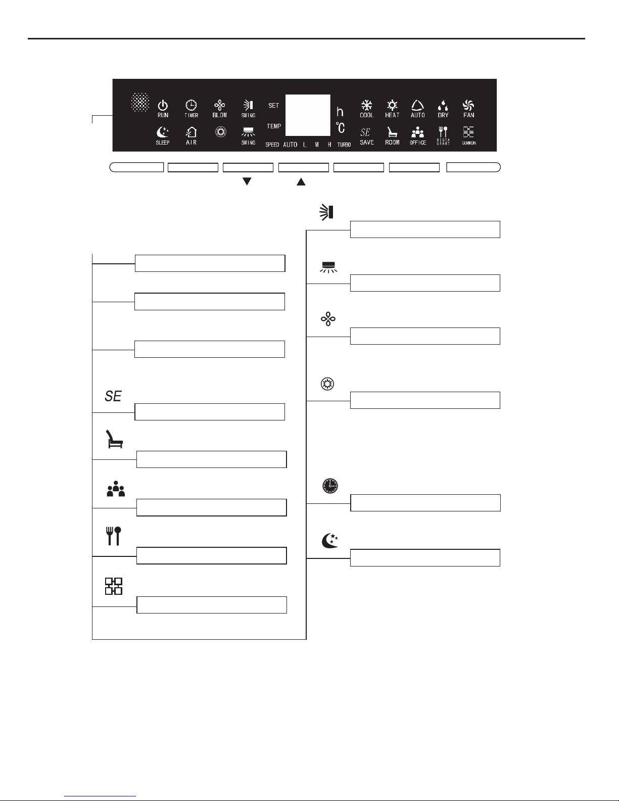
6.1 Instructions of Control Buttons on Indoor Panel
6. Function and Control
Model:GVA48AH-M3NNA5C
●
●
E-HEATER
Buttons function and displayer
and
and
●
●
●
Press this button, to turn on the unit.
When unit is turned on, the original
setting like Timer, Sleep function will
be canceled.Note: When the unit is
running in Dry mode, press ON/OFF
button that can turn on the unit directly.
ON/OFF
ON/OFF Button
●
When the unit start up running,
the status light will display in red
indicated as power turn-on and free-duty.
Mode
Mode Button
Press the button, the circulating changes
of mode are shown as below:
Auto Cooling Dehumidification
Heating
Air Supply
Auto: the controller will determine its
operation mode according to changes
of room temperatures under this mode.
Cooling: display cooling state.
Dehumidification: reduce temperature
and keep the setting room temperature
without any change.
Air supply: The compressor doesn't on
work and only the indoor blower is on
running under this mode.
Heating: Display the state of heating.
(Note: Single-cooling machine is not
equipped with heating mode)
Button
Under the situation without setting
the function, press
and
buttons,
the setting temperature goes up
and down 1 , the regulating range
is from 16 to 30
.
Under the conditions of setting the
functions, can proceed with the
round-trip option of this function (set
and
opposite direction of
circulation).
Keep pressing
and
buttons
for 3 seconds continuously, functions
of all buttons on the display panel
will be conductively-closed, and then
press any button, the buzzer will
ring once while "LC" is flashing for
three times on the location of double
8 and resume to normal display so
as to prompt users that the buttons
have been locked up.When keep
pressing again the two buttons for
another 3 seconds continuously,
the function of lockup will be removed
and resume to display in normal state.
Speed
Function AMB. Mode
ON/OFF
19

Service Manual
●
●
“
→
→
→
→
→
”
●
E-HEATER
Buttons function and displayer
Speed
Function AMB.
Mode ON/OFF
and
and Buttons (Continued)
After switch-on at first time, if without
any button input:1. consecutively press
twice of buttons in 20 seconds and
soon access to the running of forced
heating.After the blades of blowing up
and down opens to the minimum position,
start up running of all loads, indoor and
outdoor high-speed blowers. All characters
will be displayed when the non-inductive
thermometer bulb is broken down. The
fault codes of breakdown will be displayed
when the inductive thermometer bulb is
broken down and then the buzzer rings.
After shutdown for five minutes or
receiving shutdown signal within 5
minutes, it enter the status of normal
standby. 2. consecutively press twice
of buttons in 20 seconds and soon
access to the running of forced cooling.
After the blades of blowing up and down
opens to the minimum position,start up
running of all loads, indoor and outdoor
high-speed blowers besides the fourway valve and then the buzzer rings.
After shutdown for five minutes or
receiving shutdown signal within 5
minutes,it enter the status of normal
standby.
The 1 and 2 Functions are for trial use
only.
Speed
Speed Button
Press this button, the speed
can
shift in the circulation among of
Auto Low
Medium
High
Super
Auto
Note: the function of forced low
speed under operation of dehumi-
dification is not available.
AMB. Button
Press this button, AMB.
circulating
changes set forth below:
Energy saving
Living Room
Conference/Office
Restaurant
Normal
●
Adjustable method of AMB.
Button:
The switch-on of
AMB.
mode
at first time is the default of
normal
mode,when shutting down
and
starting up again,the AMB.
mod will
keep the setting status before
last
shutting down. Under the modes
of
energy-saving, conference/office
and restaurant,the sleep function
will be automatically cancelled.
And the sleep function is not
adjustable: sleep function is only
available on service for cooling,
dehumidification and heating under
normal mode.
AMB.
20

Service Manual
●
●
●
●
●
E-HEATER
Buttons function and displayer
Speed
Function
AMB.
Mode
ON/OFF
AMB.
AMB. Buttons (Continued)
Under the modes of living room,
restaurant, conference/office,The
setting temperature, speed,
blowing
up and down as well as left
and right
can be adjustable. If users
change
the
setting temperature,
speed,
blowing
up and down as well
as
left and right, the operation will run
in accordance with the status of setting
adjustment. The services setting of
blowing up and down as well as left
and right of next time start-up will be
remained before last shutdown while
the setting temperature and speed
will run with the default.
Under the energy-saving mode, while
the heating service is on running, the
setting temperature,
speed,
blowing
up and down as well as left
and
right can be adjustable. If users
change the setting speed, blowing
up and down as well as left and right,
it will run according the status of users'
setting adjustment.But the setting
temperature under the energy-saving
cooling function can not be adjusted.
T
he modes of living room, restaurant,
conference/office can only be called
out by pressing buttons of air con-
ditioner panel. If receiving the signal from remote control when the
air conditioner is running the modes
of living room, restaurant, conference/office, it will exit from the abo-
vementioned modes and run according to the modes of remote control.
Function
Function Button
Under the status of switch-on, Every
●
time press the function button, the
settings of up and down, left and right,
drying, concurrent heating, timing, air
renewal, setting and room temperature
can be shifted in sequence. When a
certain character is flashing, it in-
dicates can proceed its setting and
go on setting by press buttons.
The action will be confirmed if
without receiving other operating
order in 5 seconds. Or press the
function button to leave for the confirm.
Press the function button under the
status of running drying service
can directly proceed shutdown.
Press the function button under
the status of shutdown and nondrying can proceed timing setting.
AMB.
AMB.Buttons (Continued)
21
Service Manual
●
●
●
●
●
●
●
●
●
●
●
●
●
E-HEATER
Buttons function and displayer
Speed
Function
AMB.
Mode
ON/OFF
Setting
Display setting temperature.
Room temperature
Indicate temperature of indoor
circumstances.
Supper strong
When the typeface light is on, it
indicates setting the super strong
function.
Mode of save
Indicate mode of save.
Mode of room
Indicate mode of room.
Office mode
Indicate mode of office.
SAVE
ROOM
OFFICE
Mode of restaurant
Indicate mode of restaurant.
RESTAURANT
Common mode
Indicate common mode.
COMMON
Status of swing
Display status of swing.
Swing
BLOW Function
When the typeface light is on, it
indicates setting the BLOW function.
BLOW
TIMER Function
When the typeface light is on, it
indicates setting the timer function.
TIMER
SLEEP Function
When the typeface light is on, it
indicates setting the sleep function.
SLEEP
Status of swing
Display status of swing.
Swing
●
E-HEATER
This icon on the displayer turns
on,indicates that the E-HEATER
function turned on,the
electrical
heating, according to
a certain
condition, it can put into use.
FunctionE-HEATER
22
Service Manual
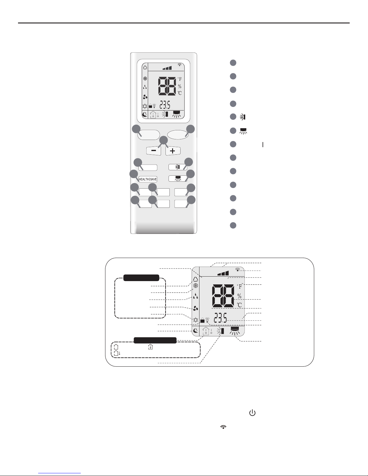
6.2 Remote Controller Introduction
Buttons on Remote Controller
Introduction
for Icons on Display Screen
Introduction for Buttons on Remote Controller
Note:
●
This is a
general use remote controller, it could be used for the air conditioners with multifunction; For some function, which
the model doesn't have, if press the corresponding button on the remote controller that the unit will keep the original running
status.
●
After putting through
the power, the air conditioner will give out a sound. Operation indictor "
" is
ON (red indicator). After
that, you can operate the air conditioner by using remote controller.
●
At ON status,
after each pressing button on remote controller, the signal icon“
”on remote controller
will ash once. Air
conditioner will give out a sound, which indicates the signal has been sent to air conditioner.
●
At OFF status, display screen on remote controller displays set temperature.
At on status, display screen on remote controller displays the corresponding startup function’s icon.
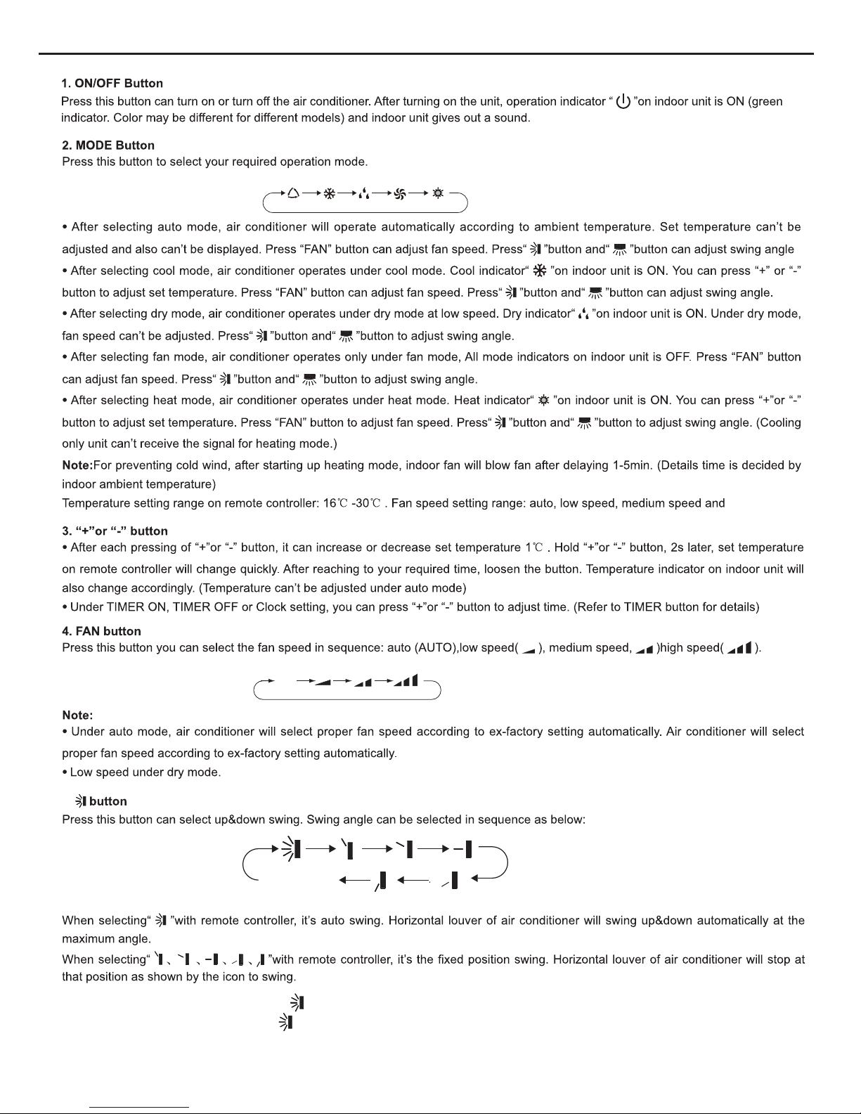
ON/OFF Button
2
3
1
5
6
4
9
10
8
12
13
11
MODE Button
+/- Button
X-FAN Button
TEMP Button
TURBO Button
SLEEP Button
LIGHT Button
Button
HEALTH SAVE Button
7
Button
TIMER Button
FAN Button
FAN
AUTO
OPER
HEALTH
AIR
FILTER
TURBO
ON/OFF
X-FAN
HOUR
HUMIDITY
ON/OFF
MODE
FAN
X-FAN
TURBO
TEMP
TIMER
SLEEP
LIGHT
2
10
7
9
12
8
3
11
6
5
13
4
1
Child lock
Left&right swing
Sleep mode
Auto mode
Air mode
Cool mode
Heat mode
Fan mode
Dry mode
Up&down swing
:Indoor ambient temp.:Set temp.
:Outdoor ambient tep.
FAN
OPER
AUTO
HEALTH
AIR
FILTER
TURBO
ON/OFF
X-FAN
HOUR
HUMIDITY
TIMER ON/TIMER OFF
Set time
Light
Send signal
Sleep mode
X-fan
Set fan speed
Set temperature
Turbo mode
Temp. display type
Operation mode
operation mode
Temp.display type
23
Service Manual
AUTO COOL DRYFAN HEAT
Auto
no display
(horizontal louvers
stops at current position)
high speed.
5.
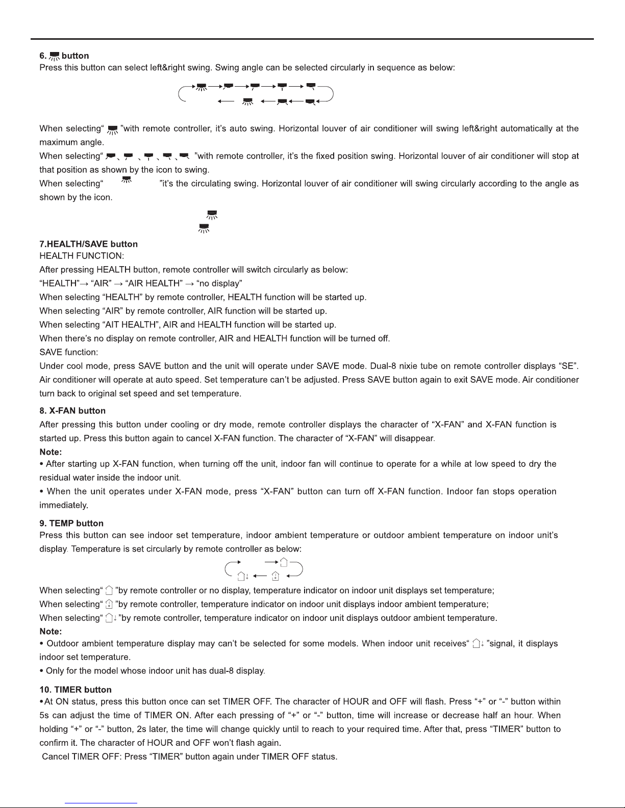
Under unit off status, press “+” button and button simultaneously to switch between simple swing setting and fixed-angle swing setting.
During switching the two swing settings, icon will blink for 2s.
24
Service Manual
no display
no display
(swing angle is
displayed dynamically)
(horizontal louvers
stops at current position)
(swing angle is
displayed dynamically)
Under unit off status, press “+” button and button simultaneously to switch between simple swing setting and fixed-angle swing setting.
During switching the two swing settings, icon will blink for 2s.
(Note:Health function is not available for some models.)
25

Service Manual
11. TURBO button
When pressing
this button under cooling or heating mode, air conditioner will enter into quick cooling or quick heating mode. The
character of “TURBO” is displayed on remote controller. Press this button again to exit turbo function and the character of “TURBO” will be
disappeared on remote controller.
13. LIGHT button
Press this button can turn off the light for indoor unit’s display“
”icon
on remote controller will disappear. Press this button again to turn
on the light for indoor unit’s display“
”icon on remote controller will be displayed.
12. SLEEP button
Press this
button under cooling, heating or drying mode can start up sleep function“
”icon will be displayed on remote controlle
r
. Press
this button again to cancel sleep function“
”icon on remote controller will be displayed.
●
At OFF status, press this button once can set TIMER ON. Please refer to TIMER of
f for detailed operation.
Cancel TIMER ON: Press “TIMER” button again under TIMER ON status.
Note:
●
Time setting range: 0.5-24 hours.
●
Time interval between two operations can’t exceed 5s. Otherwise, remote controller will exit the setting status automatically.
Press
“+” and “-” buttons simultaneously can turn on or turn off child lock function. When child lock function is started up“
”icon will be
displayed on remote controller. If operate remote controller“
”icon will ash three times, while remote controller won’t send signal.
Switchover function for temperature display:
After turning of
f the unit by remote controller, press “-” button and “MODE” button simultaneously to switch between ℃and ℉.
Function Introduction for Combination Buttons
Child lock function:
Note:
● During
operation, point the remote control signal sender at the receiving window on
indoor unit.
● The distance between signal sender and receiving window should be no more than 8m,
and there should be no obstacles between them.
● Signal may be interfered easily in the room where there is uorescent lamp or wireless
telephone; remote controller should be close to indoor unit during operation.
● Replace new batteries of the same model when replacement is required.
● When you don’t use remote controller for a long time, please take out the batteries.
● If the display on remote controller is fuzzy or there’s no display, please replace
batteries.
Signal sender
Battery
Cover of
battery box
Remove
Reinstall
1. After putting through the power, press “ON/OFF” button on remote controller to turn on the air conditioner.
2. Press "MODE" button to select your required mode:AUTO,COOL,DRY,FAN,HEAT.
3. Press “+” or “-“ button to set your required temperature. (Temperature can’t be
adjusted under auto mode).
4. Press ‘FAN” button to set your required fan speed: auto, low, medium and high speed.
5. Press “
”button and“ ”button to select fan blowing angle.
1.Press the back side of remote controller marked with“
”as shown in the g, and then push out the cover
of battery box along the arrow direction.
2. Replace two 7# (AAA
1.5V) dry batteries, and make sure the position of “+” polar and “-“ polar are correct.
3. Reinstall the cover of battery box.
Operation Guide
Replacement of Batteries in Remote Controller
26

Service Manual
6.3 Introduction of Each Mode Function
start cooling
original running status
stop cooling
compressor
outdoor fan
indoor fan
run
stop
setting fan speed
6mins
3mins
6mins
Tamb.
Tpreset+1
Tpreset
-1
cooling
drying
stop running
compressor
outdoor fan
indoor fan
run
stop
low fan speed
low fan speed
low fan speed
6mins
6mins
4mins
4mins
Tpreset+2
Tpreset
-2
Tamb.
1. Running Mode
1. cooling; 2. dry; 3. fan; 4: heating; 5. AUTO; 6. others (Freon recovery mode).
2.3.Temperature Para meter
1. Indoor ambient temperature Tamb. (adopt 15K temperature sensor, external connect 15K partial resistance);
2. Outdoor ambient temperature T
outdoor amb.
(adopt 15K temperature sensor, external connect 15K partial resistance);
3. Discharge temperature (Tdischarge)
4. Indoor evaporator tube temperature Te vaporator (adopt 20K temperature sensor, external connect 20K partial resistance);
5. Outdoor condenser tube temperature Tcondenser (adopt 20K temperature sensor, external connect 20K partial resistance).
Basic Functions of System
In all modes, once the compressor is started up, it will run within 6mins all the time; once the compressor is stopped, it can only be started
up after 3mins delayed.
(1) Cooli ng Mode
When Tamb.≥ Tpreset+1
, the unit will run in cooling mode. Meanwhile, compressor, outdoor fan will start running, and indoor will run at
setting fan speed;
When Ta mb.
Tpreset-1 , the unit is at OFF status in cooling mode. Meanwhile, compressor, outdoor fan will all stop running, while
indoor fan will run at setting fan speed;
When Tpreset-1
<Tamb.<Tpreset+1 , the unit will keep previous running status.
In this mode, the temperature setting range is 16 ~30 and the initial value is 25 .
(2) Dry Mode
When Tamb.>Tpreset+2
, the unit will run in cooling mode. Meanwhile, compressor and outdoor fan will start running, and indoor fan will
run at low fan speed;
When Tpreset-2
Tamb. Tpreset+2 , compressor and outdoor fan will run for 6mins and then stop for 4 mins, and they will run like that
circularly. Indoor fan will run at low fan speed;
When Tamb.<Tpreset-2
, compressor and outdoor fan will stop running, while indoor fan will run at low fan speed.
In this mode, the temperature setting range is 16 ~30 and the initial value is 25 .
1. Working conditions and process of cooling
1. Working conditions and process of dry
27

Service Manual
stop heating
original running status
start heating
stop run
compressor
outdoor fan
indoor fan
reversing valve
6mins
3mins
6mins
setting fan speed
10S
low fan speed
low fan speed
anti cold air
anti cold air
Tpreset+1
Tpreset
-1
(3) Heating Mode (this mode is not available for cooling onl y un it)
When Tamb.
Tpreset-1 , the unit will run in heating mode. Meanwhile, compressor and outdoor fan will start running. Indoor fan may
be start running after delayed for a period of time to prevent blowing out cold air. If the unit turns to heating mode for the first time or
switches to heating mode from other modes, the four-way valve will be energized after compressor was started up for the first time for20s.
When Tamb.≥Tpreset+1
, compressor and outdoor fan will stop running. The four-way valve is energized all the same and indoor fan
will stop running after running at low fan speed for 10s;
When Tpreset-1
<Tamb.<Tpreset+1 , the unit will keep original running status;
In this mode, the temperature setting range is 16 ~30 and the initial value is 25 . When tuning off theunit in heating mode or
switching to other modes from heating mode, the four-way valve will be de-energized after 2mins delayed.
When turning off the unit, if the complete unit is at running status in heating mode, the unit will stop running when reaching the
setting temperature and the unit will be turned off after lowing residual heat for 10s. If the unit is at the status of blowing residual
heat when the unit is stopped after reaching the temperature point, the unit will continue to blow residual heat and then it will be
turned off; if the unit is stopped after reaching the temperature and indoor fan is stopped, the unit will be turned off directly without
blowing residual heat.
System will defrost intelligently and automatically. When it’s detected that the system is reached the defrosting condition, the system will
turn to defrosting status;
After defrosting is started up, H1 will be displayed. If there’s auxiliary heating, auxiliary heating will be stopped and then compressor,
indoor fan and outdoor fan will stop running after 1min delayed. 3mins later, the four-way valve will be closed. After four-way valve has
closed for 30s, compressor will be started up.
After defrosting is finished, compressor will stop running, while the four-way valve will be start up. 30s later, compressor and outdoor fan
will be restarted up and turn to the next periods. Indoor fan is running at anti cold air status.
Defrosting time can’t exceeds 12mins at the most.
Auxiliary heating can be turned on/off by buttons.
If auxiliary heating is at ON status, when indoor fan is running, and indoor ambient temperature and air discharge temperature arelow,
auxiliary heater will start running;
When indoor fan isn’ t running, or indoor ambient temperature is high, or air discharge temperature is high, auxiliary heater will stop
running. Once the auxiliary heater is stopped, it can only be restarted up after 2mins delayed.
If auxiliary heating is set OFF, the auxiliary heating will be turned off directly.
4 Fan Mo de
Indoor fan is running at setting fan speed: auto fan speed low fan speed medium fan speed high fan speed
The temperature setting range is 16 ~30 and the initial value is 25 .
(5
) Auto Mode
In this mode, the system will select the running mode (cooling, dry, heating, fan) automatically according to the change of ambient
temperature.
Once the mode is started up, the unit will only switch to the running status under auto mode according to Ta mb after it has run for
30s at least.
1. Working condition and process for heating
3. Working condition for auxiliary heating
2. Defrosting condition and process
10S
28

Service Manual
(0°)
( 0 ) °
Freon Recovery Mode
Notice: 1. After refrigerant is recovered, if the recovery operation should be operated again, please cut off the power at first and then put
That’s the recovery operation method for refrigerant:
1. After the A/C is energized for the first time, set the A/C at FAN mode, low fan speed by remote controller and the indoo
r
temperature is set as 20
; Meanwhile, indoor fan will start running.
2. Press the light button on remote controller for twice successively within 5s; meanwhile, indoor fan and compressor will start runnin
g
automatically.
3. After compressor has run for 3mins, close the cut-off valve completely.
4. When the protector for Low-pressure switch has an action, compressor and outdoor unit will stop running automatically. Please close
the cut-off valve immediately.
5. After stopping blowing wind by remote controller, the refrigerant recovery operation is finished completely.
through the power again.
2. Above methods are applicable for the movement or reinstallation of indoor unit or outdoor unit; during this process, the low
voltage sw
itch c
an’t be short circuited.
4.
Other Controls
1. Sleep Function
Sleep in cooling mode:
When initial temperature is set as 16~23
, after sleep function is started up, the temperature will increase by 1 every 1hr. After the
temperature has increased by 3 , the unit will keep this temperature. After the uni t has run for 7hrs, the temperature will decrease 1
and then the unit will run at this temperature all the time.
When initial temperature is set as 24~27 , after sleep function is started up, the temperature will increase by 1 every 1hr. After the
temperature has increased by 2
, the unit will keep this temperature. After the unit has run for 7hrs, the temperature will decrease 1
and then the unit will run at this temperature all the time.
When initial temperature is set as 28~29
, after sleep function is started up, the temperature will increase by 1 every 1hr. After the
temperature has increased by 1
, the unit will keep this temperature. After the unit has run for 7hrs, the temperature will decrease 1
and then the unit will run at this temperature all the time.
When initial temperature is set as 30
, the unit will run at this temperature. After the unit has run for 7hrs, the temperature will
decrease by 1
and then the unit will run at this temperature all the time.
Sleep in heating mode:
When initial temperature is set as 16
, the unit will run at this temperature all the time;
When initial temperature is set as 17~20
, after sleep function is started up, the temperature will decrease by 1 every 1hr. After the
temperature has decreased for 1
, the unit will keep this temperature.
When initial temperature is set as 21~27
, after sleep function is started up, the temperature will decrease by 1 every 1hr.After the
temperature has decreased for 2
, the unit will keep this temperature.
When initial temperature is set as 28~30
, after sleep function is started up, the temperature will decrease by 1 every 1hr.After the
temperature has decreased for 3 , the unit will keep this temperature.
Sleep in dry mode:
When setting sleep function in dry mode, after the sleep function has run for 1hr, Tpreset will increase by 1
and it will increase by
another 1
after 2hrs. Tpreset will increase by 2 at all within 2hrs and then the unit will run at this temperature.
Sleep in fan mode and auto mode:
Sleep function is nor available in fan mode and auto mode.
2. Timer Function
Timer ON: Timer ON can be set at the OFF status of the unit. After timer ON is reached, controller will run according to the setting mode.
The time setting range is 0.5~25hrs and the interval is 0.5hr. If the time on display screen is less than 10hrs,the display interval is 0.5hr;
if the time is more than 10hrs, the display interval is 1hr.
Timer OFF: Timer OFF can be set at the ON status of the unit. After timer OFF is reached, the unit will be turned off. The time setting
range is 0.5~25hrs and the setting interval is 0.5hr. If the time on display screen is less than 10hrs, the display interval is 0.5hr; if the
time is more than 10hrs, the display interval is 1hr.
3. Swing Control
Swing motor can be turned on/off by pressing the swing button on remote controller. Swing is valid only when the indoor fan is running.
Right & left swing:
swing blade has 7 kinds of status:
angle 1, angle 2, angle 3,
angle 4, angle 5, swing, stop. After the unit is turned on by the ON/OFF button on
control panel every time, the default status of swing is OFF and the position is
angle 3.
After the unit is turned on by remote controller, the status of swing motor is basing on the
display status on remote controller After the unit is energized every time, right & left swing
motor will be reset.
UP & down swing: when turning off the unit, the swing blade will stop at the starting point (zero
position). When turning on the unit, there are 7 kinds of status: angle 1 (max position), angle
2,
angle 3, angle 4, angle 5 (min position), swing, stop. If turn on the unit by the
ON/OFF button on control panel, the setting swing status is basing on the status before turning off
the unit; while if turn on the unit by remote controller, the setting swing status is basing on the
status on remote controller (if the receiving remote controller is 35, 25, 24, 14 or 13, it’s
swing). When turning on the unit each time (including turn on the unit by remote controller or
control panel), if the setting swing status is not
stop, then it will at the actual swing status; if the
setting swing status is
stop, after turning the unit, it will be defaulted at angle 3 in cooling, angle
4 in heating and angle 3 in dry. As for mode switchover, it will also switch like that until the setting
swing status is not
stop, then the above compulsory default status will be cancelled.
set this place as the starting point
set this place as
the starting point
6
1.
2.
3.
4.
5.
29

Service Manual
When turning on the unit each time, the swing blade must be open to angle 5 (mini position), and then compressor, fan etc. can run.
When switching on controller or turning off the unit each time, the swing blade must be at OFF status.
4. Buzzer
Upon energization or operation, the buzzer will give out pleasant sound (digital chord).
5. Auto Fan Speed Control of Indoor fan
In auto fan speed, indoor fan will select high, medium or low fan speed automatically according to the change of ambient temper ature.
For the switchover between any two kinds of fan speed, the unit must be make sure that it has run at each fan speed for 3mins and 30s
at least.
6.
AIR Function
it’s reserved for some models
AIR function is invalid when the unit is turned off. Upon receiving the order for starting up AIR function from remote controller or control
panel, indoor fan will be turned on and the AIR function will be started up; once receiving the order for turning off AIR function, AIR
function will be turned off. After the unit is turned off, AIR function will be cleared automatically.
7. BLOW function
Blow function can be turned on/off by the FUNCTION button on control panel or BLOW·E-HEATER button on remote controller.
If start up BLOW function in cooling or dry mode, after the unit is turned off, indoor unit will still run for a few minutes to dry the water
inside the unit, and then the indoor unit will be turned off automatically.
8. Turbo Function
In cooling and heating mode, turbo function can be turned on/off (there’s no turbo function in auto, dry and fan mode) by the turbo button
After pressing turbo button for once, remote controller will display the characters of “turbo” and fan speed won’t change, Meanwhile,
indoor fan will run at super-high fan speed and display panel will display the super-high fan speed; After repressing turbo button, th
turbo function will be quitted and the characters of “turbo” on remote controller will be disappeared. Meanwhile, indoor fan will turn back
to setting fan speed. Super-high fan speed will also be quitted after operating the fan speed button and the fan speed will als o be
changed correspondingly. Display panel will display the setting fan speed.
Turbo function is default to be turned off when remote controller is energized.
When restarting up the unit or switching the mode, turbo function will be memorized.
When restarting up the unit by remote controller and controller or switch to cooling or heating mode, turbo function will be memorized.
While when switching to auto, dry or fan mode, the turbo function is unavailable.
9. Power-off Memory Function
When re-energizating the unit after power failure, the unit will run at the memory content. Memory content :mode, up&down swin
(7kinds of status), right and left swing (7 kinds of status), setting temperature, setting fan speed, light, timer, turbo, AIR, health and
environment mode.
If the unit is at ON status after power failure, compressor will be started up 3mins delayed after energization; if the unit is at OFF status,
compressor will be started up without 3mins delayed.
If the timer hasn’t been reached before power failure, the unit will time again according to the setting timer before power failure.
5.Protective Measures
When cooling in cooling mode or dry mode (that’s Tamb>Tpreset+2 ), if it’s detected that the evaporator tube temperature is too low
the system will turn to antifreezing protection status. Meanwhile, compressor and outdoor fan will stop running, while indoor fan and
swing motor will keep original status.When evaporator tube temperature resumes to normal range and compressor has stopped for
6mins, controller will run at the setting mode.
Buttons won’t be shielded during the antifreezing protection.
When the high-pressure protection is detected for 3s successively, all loads will be turned off. Meanwhile, all buttons and signal will be
shielded and E1 will be displayed. When it’s detected that the high-pressure protection of compressor has been released for 6s
successively, the shield for button and signal will be released and E1 will still be displayed. E1 can be cleared after pressing ON/OF
button to turn off the unit. The unit will resume running after repressing ON/OFF button.
This function is unavailable for some modes. But if the controller is the general controller and the shielded wire of low-pressur
protection is loosened or not connected well, it will take it as low-pressure protection by mistake. The details are as below:
1. After compressor is started up for 2mins, it will begin to detect the signal of low pressure switch. If it’s detected that the low pressure
switch is broken for 1mins successively, the complete unit will stop running. 3mins later, if the low pressure switch is resumed, the unit
will resume running automatically. If low pressure switch protection occurs for 2 times successively, E3 will be displayed andthe
can’t resume running automatically to warn users that it’s leaking. After restarting up the unit and low pressure switch is resumed, the
unit will resume running.
1. Indoor antifreezing protection
2. High-pressure protection of system
3. Low-pressure protection of system
30

Service Manual
Speed Function AMB. ModeON/OFF
2. When compressor is stopped, if it’s detected that the low pressure switch is broken for 30s successively, the complete unit will stop
running. Meanwhile, E3 will be displayed and the unit can’t resume running automatically. Only after restarting up the unit and the low
pressure switch is resumed, the unit can resume sunning.
3. When compressor hasn’t been start up after energization each time, if it’s detected that the low pressure switch is broken for 1s
successively
, all loads won’t be turned on after turning on the unit, and E3 will be displayed on the display screen. E3 will still be
displayed after restarting up the unit. Only when the low pressure switch is resumed, E3 will be cleared and then all loadswill run
normally.
4. In compulsory cooling or heating mode, it will begin to detect the signal of low pressure switch after compressor has starte d up for
2mins. When it’s detected that the low pressure switch is broken for 1s successively, the complete unit will stop running and E3 will be
displayed. During compulsory heating, if outdoor ambient temperature
0 , the detection for low pressure switch will be shielded.
Correct disposal method: after cutting off the power, insert the shielded wire again to make sure that the shielded wire is connected
firmly and then restart up the unit.
4. High temperature protection for discharge pipe
After the compressor is started up, if it’s detected that the discharge temperature is too high for 30s successively, the unit will stop
running when indoor ambient temperature is reached to setting temperature. When compressor has stopped for 3mins and discharge
temperature resumes to normal range Tdischarge <90
, the complete unit will resume running.
If above protection is occurred for twice successively, the complete unit can’t resume running and E4 will be displayed. When restarting
up the unit and Tdischarge <90
, the unit will run at setting mode.
If turning on the unit to turn to heating mode or switching to heating mode from other modes, discharge protection will be shie lded for
1min when compressor is started up for the first time.
5. Indoor high temperature resistance protection
In heating mode, when it’s detected that the evaporator tube temperature is to o high, outdoor fan will stop running; when evaporator
tube temperature resumes to normal range, outdoor fan will be started up.
6. Overcurrent protection
After compressor is started up, if it’s detected that the current is exceeds I
(
0 I0
=25A) for 3s successively, the unit will stop running when
Indoor ambient temperature is reached to setting temperature. After compressor has stopped for 3mins, the unit will resume original
running status. If protection times exceeds 6 times, indicator will blink and display E5 and the unit can’ t resume original running status.
The unit can only resume running after restarting up the unit.
7. Malfunction of temperature sensor
Under ON status, it will detect the malfunction of indoor tube temperature (exclude defrosting period and the period when defrosting is
finished for 5mins) and outdoor discharge temperature sensor (in heating mode, it starts detecting the malfunction after compressor has
started up for 1min; the malfunction won’ t be detected when compressor is stopped). It’s the malfunction when they are short circuit
or broken circuit for 30s successively. When there’ s malfunction of temperature sensor, the complete unit will stop running. Meanwhile
the indicator will blink and display the corresponding error code. Malfunction of temperature sensor won’ t shield the button and remote
controller.
8. Malfunction and protection code
E1: high-pressure protection of system;
E3: low-pressure protection of system;
E4: high temperature protection for discharge pipe;
E5: overcurrent protection;
F1: malfunction of indoor ambient temperature sensor;
F2: malfunction of indoor tube temperature sensor;
F3: malfunction of outdoor ambient temperature sensor
F4: malfunction of outdoor tube temperature sensor
F5: malfunction of discharge temperature sensor
When multiple malfunctions are occurred simultaneously, each malfunction error will be displayed for 3s and they be will displayed in
cycle.
6Button
When remote controlling by remote controller:
1.If the display mode for remote controller is the heating mode and A/C is the cooling only type, A/c won’t receive other signal except
the signal for turning off the unit.
2.If pressing the invalid button on remote controller, the buzze r will still give out a sound but the function won’t be carried out.
There are those buttons on the panel: ON/FF button, mode button, ambient setting button, ▲ button, ▼button, function button, fan
speed button.
Display screen:
31

Service Manual
1. ON/OFF button
Controller is turned on/off by pressing this button. After each pressing of this button, the on/off status will be switched for once.
2. Mode button
After pressing this button, it will be selected and displayed as below:
Auto cooling dry fan heating (heat pump type)
3. Ambient setting button
After pressing AMB. button, it will be selected as below:
SAVE mode room mode office mode restaurant mode common mode
In each mode, after pressing AMB. mode on cont rol panel, the ambient mode can be selected and cycled as : SAVE mode---room
mode---office mode---restaurant mode---common mode; when the unit is turned on for the first time, ambient mode is default as
common mode; when restarting up the unit, ambient mode will keep the setting status before turning off the unit.
When using the remote controller, the unit can only turn to SAVE mode or common mode after receiving the order from remote
controller, and the unit will run according to the order transmitted by remote controller all the time.
In SAVE mode, room mode, office mode or restaurant mode, sleep will be cancelled automatically and sleep can’t be adjusted;
Sleep is only valid in cooling, dry and heating mode under the common mode.
Room, restaurant and office modes
Cooling and heating mode: setting temperature, fan speed and swing will run at the default status. If users have adjusted the
parameters, they will run according to adjusting status. 30mins later, it will turn back to auto adjusting status; when restating the
unit, swing will keep the status before turning off the unit.
Fan, dry and auto mode: running status is the same as that in common mode.
SAVE mode
In cooling mode: setting temperature and fan speed can be adjusted automatically; if users have adjusted the setting temperature
and setting fan speed, it will run according to the adjusting status. 30mins later, it will turn back to auto adjusting status.
Heating, fan, dry and auto mode: the running status is the same as that in common mode.
Notice : room, restaurant and office mode can only be adjusted by buttons on control panel. If controller is receiving the order from
remote controller when it’s running in room, rest aurant or office mode, those modes will be quitted and it will run according to the
mode on remote controller.
4. Selection button for setting temperature (▲and▼)
(1) During the status when don’t set the function, after pressing ▲ button or ▼button for once, the setting temperature will increase or
decrease for 1
and the temperature setting range is 16 ~30 .
(2) During the status when setting the function, the function can be s
elected circularly. the circulatory direction for ▲and▼ is opposite
up & down swing swing, stop swinging.
right & left (swing): swing, stop swinging.
blow: start up blow, turn off blow.
E-HEATER: start up E-HEATER, turn off E-HEATER.
TIMER: set timer and it can be adjusted among 0~24hrs. If the time is less than 10hrs, the interval is 0.5hr; if the time is more than
10hrs, the interval is 1hr.
AIR: start up AIR, turn off AIR.
Sleep: start up sleep, turn off sleep.
Health: start up the electrostatic dedusting, turn off the electrostatic dedusting.
Turbo: start up turbo, turn off turbo.
32
Service Manual
Setting: default to display the setting temperature at ON status, default to display the setting temperature at off status
Room temperature: default to display room temperature at on status, default to display to room temperature at off status.
(3) After pressing ▲ button and ▼button simultaneously, all buttons on the display panel will be shielded. When pressing any buttons,
the buzzer will give out a sound and dual 8 will display “LC”. The display will resume normal after the dual 8 blinks 3 times to warn users
that the buttons are locked. When repressing those two buttons simultaneously, shield will be released and the displaywill resume
normal status.
(4) After the unit is energized for the first time, if there isn’t any input:
If pressing ▲ buttons within 20s successively, the unit will turn to compulsory heating immediately and up & down swing blade will
open to angle I
minimum position . Meanwhile, all loads will be started up and indoor fan and outdoor fan will run at high fan speed.
When there’s no malfunction of temperature sensor, all characters will be displayed. When there’s malfunction of temperature sensor,
dual 8 will display error codes circularly and the buzzer will give out sound. When the unit is stopped 5 mins later or the unit is stopped
after receiving the signal for turning off the unit within 5mins, the unit will turn to normal standby status.
If pressing ▼button within 20s successively, the unit will turn to compulsory cooling immediately and up & down swing blade will
open to angle I (minimum position). Meanwhile, all loads will be turned on except the four-way valve and the indoor fan and outdoor fan
will run at high fan speed. When there’s no malfunction of temperature sensor, all characters will be displayed. When there’s malfunction
of temperature sensor, dual 8 will display error codes circularly and the buzzer will give out sound. When the unit is stopped 5 mins later
or the unit is stopped after receiving the signal for turning off the unit within 5mins, the unit will turn to normal standby status.
After above tests are all displayed for 2s, it will begin to detect the malfunction of indoor ambient, indoor tube temperature, outdoor
ambient, outdoor ambient, outdoor tube temperature and discharge temperature sensor. When it’s detected that there are multiple
malfunctions, each error code will be displayed for 3s and they will be displayed circularly.
Item
and are only used for testing. During this period, high pressure, overcurrent and discharge protection won’t be detected.
5. Functi on but ton
In the
ON state of the unit, after each pressing of the function button, you can switch among up&down swing, right&left swing, blow,
E-HEATER, timer, AIR, sleep, health (this is unavailable for L-shape floor standing A/C), turbo, setting and room temperature setting in
sequence. When a certain character is blinking, it means that you can set this function and you can press “▲”butt on or “▼”button to
set it. The setting will be confirmed after the setting has been set for 5 mins and there’s no change for the operation.
In blow running status, the unit will be turned off after pressing the function button. If repressing the function button, you can set the
timer or health function.
After a function is selected by function button, if the unit hasn’t been turned off and it hasn’t received the signal from remote controller
within 2 mins, the unit will circulate starting from the original setting function after repressing the function button.2mins later or the unit is
turned off or the unit has received the signal from remote controller, the unit will circulate from the first icon after repressing function
button.
6. Fan Speed Button
After pressing speed button, it will be selected and displayed as: auto low medium high
Display Method
1.Middle Number Part
(1) When there’s malfunction protection (E1, E3, E4, E5, F2, F5), the unit only displays the error code and others won’tbe displayed.
When there’s multiple malfunctions, those malfunctions will be displayed circularly.
(2)In the normal running status, when setting temperature or timer is set, the unit will display the corresponding setting for 5s. After that,
the unit will display the setting temperature and it will default to display H1 during the time of defrosting. When setting the setting
temperature, timer and temperature display, they will be displayed in sequence as below: setting temperature, timer, temperature
display and defrosting H1 and each status will be displayed for 5s. If one status (setting temperature, timer, temperature display,
defrosting H1) isn’t exist, that status will be omitted and the display will stop at
the defaulted or setting temperature display. After the unit
is energized, it defaults to display the ambient temperature.
The corresponding character and icon will be displayed simultaneously.
2. Fan Speed
When setting auto, low, medium and low fan speed, the corresponding character for the selected fan speed will be bright, and others
won’t be bright.
When setting auto, cooling, dry, fan and heating mode, the corresponding character for the selected mode will be bright and others
won’t be bright. The character and icon for the selected mode will be bright simultaneously. In auto mode, the auto and actual running
mode will be displayed at the same time.
3. Ambient Mode
Ambient mode is including 5 kinds of mode: SAVE mode, room mode, office mode, restaurant mode and common mode. The selected
ambient mode will be bright, others won’t be bright.
Up&down swing: when setting up&down swing, the icon and characterwill blink; when selecting the up&down swing, the icon and
the character of (up&down) will be displayed. When there’s no up&down swing or the swing the stopped, the icon and the
character of “up&down” won’t be displayed.
Right&left swing: when setting right&left swing, the icon and characterwill blink; when selecting the right&left swing, the icon and
the character of (right&left swing) will be displayed. When there’s no right&left swing swing or the swing the stopped, the ico n and
the character of “right&left swing” won’t be displayed.
7.
33

Service Manual
Blow: when setting blow function, the icon and character will blink; when this function is selected, the icon and character wi ll be
displayed. If the blow function hasn’t been selected, the icon and character won’t be displayed. During the time of blow, only the
icon and character are displayed, others won’t be displayed.
E-HEATER: when setting E-HEATER function, the icon and character will blink; when this function is selected, the icon and
character will be displayed. If the E-HEATER function hasn’t been selected, the icon and character won’t be displayed.
Timer: when setting timer function, the icon and character will blink; when this function is selected, the icon and characterwill be
displayed. If the timer function hasn’t been selected, the icon and character won’t be displayed.
AIR: when setting AIR function, the icon and character will blink; when this function is selected, the icon and characterwill be
displayed. If the AIR function hasn’t been selected, the icon and character won’t be displayed.
Sleep: when setting AIR function, the icon and character will blink; when this function is selected, the icon and characterwill be
displayed. If the sleep function hasn’t been selected, the icon and character won’t be displayed.
Health: when setting AIR function, the icon and character will blink; when this function is selected, the icon and characterwill be
displayed. If the health function hasn’t been selected, the icon and character won’t be displayed.
Turbo: when setting turbo function, the character will blink; when this function is selected, the character will be displayed. If the
turbo function hasn’t been selected, the character won’t be displayed.
Setting: when setting function, the character of setting will blink; when this function is selected, the character will be displayed and
the dual 8 will display the setting temperature. If the setting function hasn’t been selected, the character and setting temperature
won’t be displayed.
Room temperature: when setting function, the character of room temperature will blink; when this function is selected, the
character will be displayed and the dual 8 will display the indoor room temperature. If the room temperature function hasn’t been
selected, the character and indoor room temperature won’t be displayed.
5. Indicator Control
When the unit is at standby status after energizing, thepower LED will be bright. After the unit is turned on, the running LED will be
bright. When any one of the circumstances as below are occurred, the running LED will blink: defrosting, overcurrent protection, high
pressure protection of compressor, low pressure protection of compressor, high temperature protection of discharge pipe malfunction of
indoor tube temperature sensor, malfunction of discharge temperature sensor.
6. Light Control
LED display can be turned off by the light button on remote controller. When using remote controller to cancel “light”, the complete LED
displayer screen will go out, except the running LED. When turning off the light, if there’s signal from button or remote controller, LED will
go out after displaying for 5s.
34

Service Manual
1. Select the
installation location according to the requirement of this manual.(See the requirements in installation
part)
2. Handle unit transportation with care; the unit should not
be carried by only one person if it is more than 20kg.
3. When installing the indoor unit and outdoor unit, a sufcient xing bolt must be installed; make sure the installation
support is rm.
4. Ware safety belt if the height of working is above 2m.
5. Use equipped components or appointed components during installation.
6. Make sure no foreign objects are left in the unit after nishing installation.
Electrical Safety Precautions:
7. Notes for Installation and Maintenance
Safety Precautions:
Important!
Please read the safety precautions carefully before
installation and maintenance.
The following
contents are very important for installation
and maintenance.
Please follow the instructions below.
●The installation or maintenance must accord with the
instructions.
●Comply with all national electrical codes and local
electrical codes.
●Pay attention to the warnings and cautions in this
manual.
●All electric work must be performed by a licensed
technician according to local regulations and the
instructions given in this manual.
●Be caution during installation and maintenance. Prohibit
incorrect operation to prevent electric shock, casualty and
other accidents.
1. Cut off the power supply of air conditioner before
checking and maintenance.
2. The air condition must apply specialized circuit and
prohibit share the same circuit with other appliances.
3. The air conditioner should be installed in suitable
location and ensure the power plug is touchable.
4. Make sure each wiring terminal is connected firmly
during installation and maintenance.
5. Have the unit adequately grounded. The grounding
wire can’t be used for other purposes.
6. Must apply protective accessories such as protective
boards, cable-cross loop and wire clip.
7. The live wire, neutral wire and grounding wire of
power supply must be corresponding to the live wire,
neutral wire and grounding wire of the air conditioner.
8. The power cord and power connection wires can’t be
pressed by hard objects.
9. If power cord or connection wire is broken, it must be
replaced .
1. Avoid
contact between refrigerant and re as it generates
poisonous gas; Prohibit prolong the connection pipe by
welding.
2. Apply specied refrigerant only. Never have it mixed with
any other refrigerant. Never have air remain in the refrigerant
line as it may lead to rupture or other hazards.
3. Make sure no refrigerant gas is leaking out when
installation is completed.
4. If there is refrigerant leakage, please take sufficient
measure to minimize the density of refrigerant.
5. Never touch the refrigerant piping or compressor without
wearing glove to avoid scald or frostbite.
Warnings
Refrigerant Safety Precautions:
Improper installation may lead to re hazard,
explosion, electric shock or injury.
Installation Safety Precautions:
Part
Ⅱ
: Installation and Maintenance
10. If
the power cord or connection wire is not long enough,
please get the specialized power cord or connection wire from
the manufacture or distributor. Prohibit prolong the wire by
yourself.
11. For the air conditioner without plug, an air switch must be
installed in the circuit. The air switch should be all-pole parting
and the contact parting distance should be more than 3mm.
12. Make sure all wires and pipes are connected properly and
the valves are opened before energizing.
13. Check if there is electric leakage on the unit body. If yes,
please eliminate the electric leakage.
14. Replace the fuse with a new one of the same specication
if it is burnt down; don’t replace it with a cooper wire or
conducting wire.
15. If the unit is to be installed in a humid place, the circuit
breaker must be installed.
35
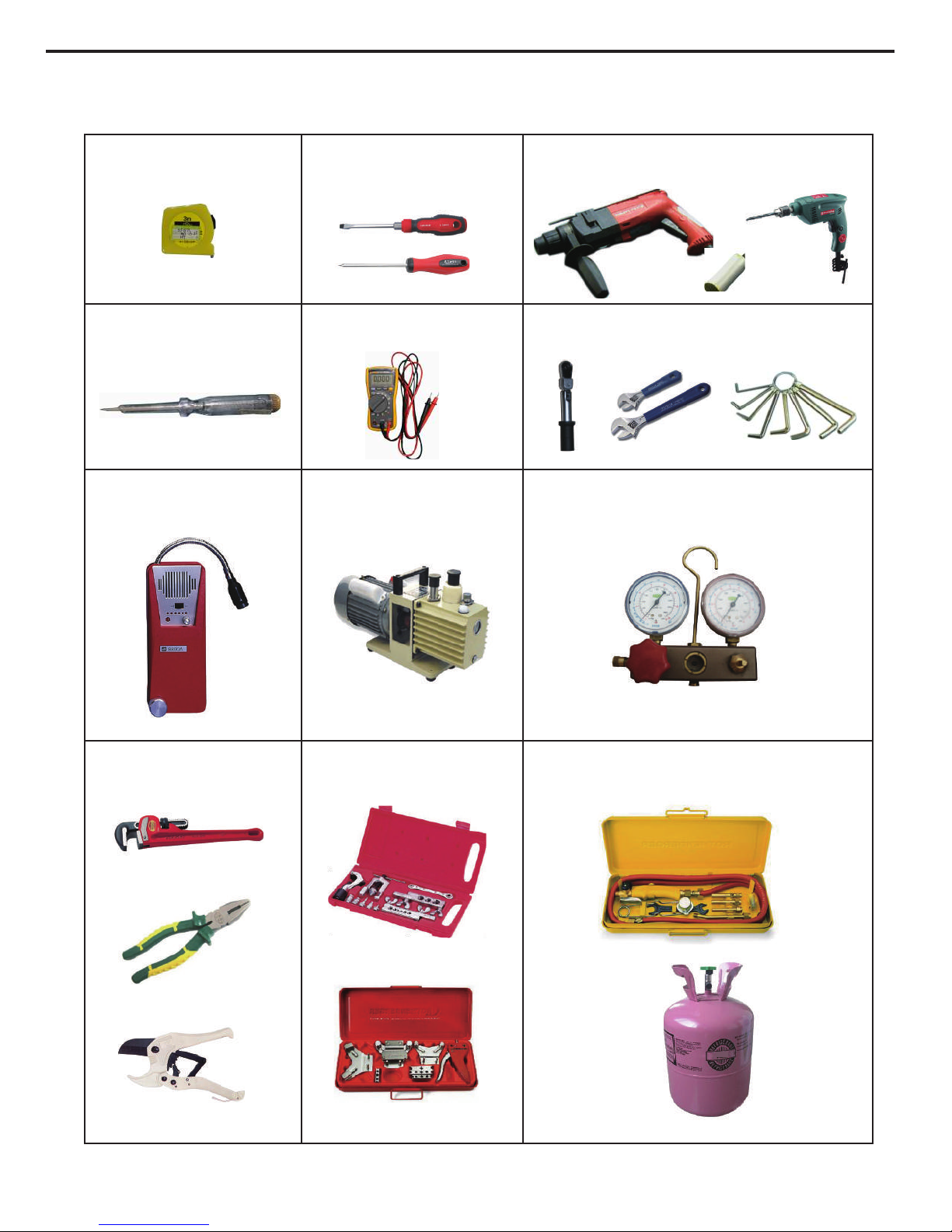
Service Manual
Main Tools for Installation and Maintenance
1. Measuring tape
4. Electroprobe
7. Electronic leakage detector
10. Pipe pliers, pipe cutter
2. Screw driver
5. Universal meter
8. V
acuum pump
11. Pipe expander
, pipe bender
3. Impact drill, drill head, electric drill
6. Torque wrench, open-end wrench, inner
hexagon spanner
9. Pressure meter
12. Soldering appliance, refrigerant container
36
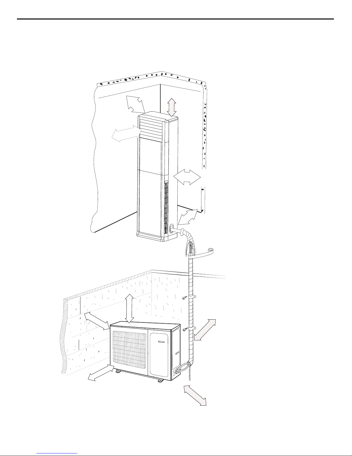
Service Manual
8. Installation
8.1 Installation Dimension Diagram
Away from obstacles
Away from wall (30cm at
Away from back side
Away from ceiling
least for piping side)
Away from wall (30cm
at least for piping side)
5cm above
10cm above
10cm above
200cm above
30cm
Away from obstacles
60cm above
Away from obstacles
10cm above
Away from obstacles
Away from obstacled
Away from wall
10cm above
60cm above
200cm above
37
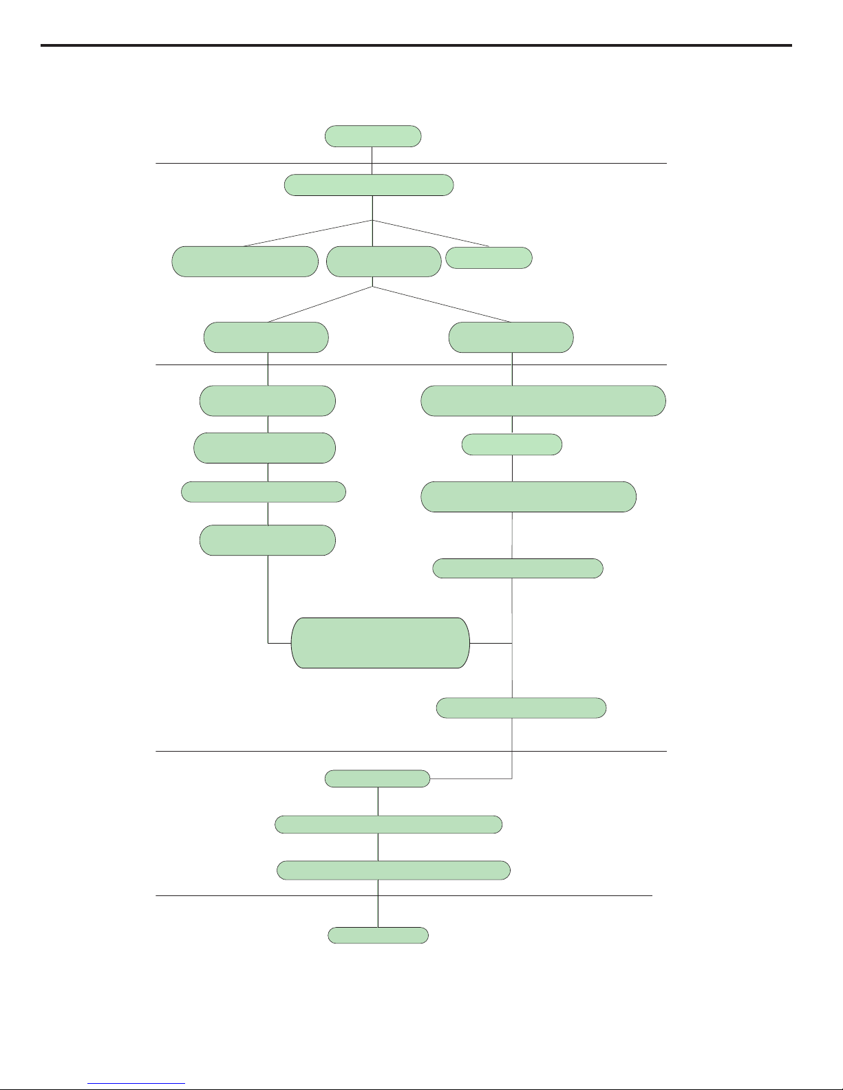
Service Manual
8.2 Installation Procedures
Preparation before installation
Prepare tools
Read the requirements
for electric connection
select installation
location
Select indoor unit
installation location
Drill wall holes
Connect pipes of indoor
unit and drainage pipe
Connect wires of indoor unit
Connect wires of outdoor unit
Bind up pipes
Make the bound pipes pass
through the wall hole and then
connect outdoor unit
Neaten the pipes
Vacuum pumping and leakage detection
Check after installation and test operation
Finish installation
Note: this flow is only for reference; please find the more detailed installation steps in this section.
Select outdoor unit
installation location
Install the support of outdoor unit
(select it according to the actual situation)
Install drainage joint of outdoor unit
(only for cooling and heating unit)
Connect pipes of outdoor unit
Start installation
Fix outdoor unit
38

Service Manual
Indoor
5-10
°
Outdoor
Φ70mm
Safety precaution:
1. Must
follow the electric safety regulations when installing the
unit.
2. If the supply cord is damaged, it must be replaced by the
manufacturer or its
service agent or a similarly qualied person in order to avoid a
hazard.
3. According to the local safety regulations, use qualied power
supply circuit and
4. A air switch having a contact separation of at least 3mm in
all poles should be air switch.
xed in xed wiring.
5. The appliance shall be installed in accordance with national
wiring regulation.
6. The air switch must have the functions of magnetic tripping
and heat tripping in order to prevent short circuit or overload.
Please install the air switch with suitable capacity according to
the sheet below.
7. Make sure the power supply matches with the requirement
of air conditioner.
8. Properly connect the live wire, neutral wire and grounding
wire of power socket.
9. Be sure to cut off the power supply before proceeding any
work related to electric safety.
10. Do not put through the power before nishing installation.
Unstable power supply or incorrect wiring may result in electric
shock, re hazard or malfunction. Please install proper power
supply cables before using the air conditioner.
Grounding Requirement:
1. The air conditioner is rst class electric appliance. It must
be properly grounded with specialized grounding device by
a professional. Please make sure it is always grounded
effectively, otherwise it may cause electric shock.
2. The yellow-green wire in air conditioner is grounding wire,
which can't be used for other purposes.
3. The grounding resistance should comply with national
electric safety regulations.
8.3 Installation Parts-Checking
8.6 Installation of Indoor Unit
8.4 Selection of Installation Location
8.5 Electric Connection Requirement
Model Capacity of air switch
48/60K 25A
Model Piping hole
48/60K Φ70mm
Basic Requirement:
Installing the unit in the following places may cause
malfunction. If it is unavoidable, please consult the local dealer:
1.The place with strong heat sources, vapors, flammable or
explosive gas, or volatile objects spread in the air.
2.The place with high-frequency devices (such as welding
machine, medical equipment).
3. The place near coast area.
4. The place with oil or fumes in the air.
5. The place with sulfureted gas.
6. Other places with special circumstances.
7. Please try your best to keep way from uorescent lamp.
Step one: Choosing Installation Iocation
Recommend the installation location to the client and then
conrm it with the client.
Step two: open piping hole
1.Choose the position of piping hole according to the direction
of outlet pipe.
2.Open a piping hole with the diameter of Φ70mm on the
selected outlet pipe position. In order to drain smoothly, slant
the piping hole on the wall slightly downward to the outdoor
side with the gradient of 5-10°. (As show in Fig.1)
Indoor Unit:
1. Avoid installing the indoor unit in a place where generated or
leaked inammable gas will stay.
2. Avoid installing the indoor unit in a moist place or in a place
where oil may be splashed on the unit.
3. Select a location where outlet air may reach each corner of
the room.
4. Select a location where connection pipe can be led to
outdoor conveniently.
5. Select a location where air inlet and outlet won't be blocked.
6. Select a location with least affection of outdoor air.
7. Select a location with rm and at oor.
8. Retain sufcient space for maintenance and installation.
9. Ensure the installation meets the requirement of installation
dimension diagram.
10.Do not use the unit in the immediate surroundings of a
laundry a bath a shower or a swimming pool.
Outdoor Unit:
1. Select a location where the noise and outow air emitted by
the outdoor unit will not affect neighborhood.
2. The location should be well ventilated and dry, in which the
outdoor unit won't be exposed directly to sunlight or strong
wind.
3. The location should be able to withstand the weight of
outdoor unit.
4. Make sure that the installation follows the requirement of
installation dimension diagram.
5. Select a location which is out of reach for children and far
away from animals or plants. If it is unavoidable, please add
fence for safety purpose.
6. The height difference between indoor unit and outdoor unit
should be within 5m. The length of connection pipe should be
within 10m.
Fig.1
No. Name No. Name
1 Indoor unit 7 Sealing gum
2 Outdoor unit 8 Wrapping tape
3 Connection pipe 9
Support of outdoor
unit
4 Drainage pipe 10 Fixing screw
5
Connecting
cable(power cord)
11
Drainage plug(cooling
and heating unit)
6 Wall pipe 12
Owner’s manual,
remote controller
1.Please contact the local agent for installation.
2.Don't use unqualied power cord.
Note:
39
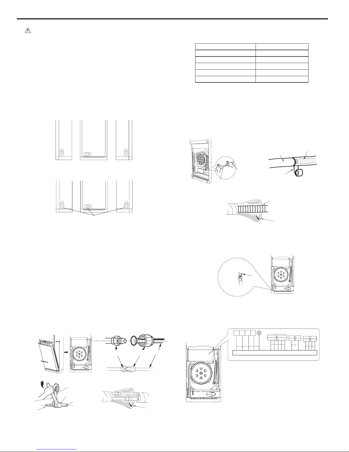
Service Manual
1.Pay attention to
dust prevention and take relevant
safety measures when opening the hole.
2.The plastic expansion particles are not provided and
should be bought locally.
Note:
Step three: outlet pipe
1. The pipe
can be led out in the direction of left, right or rear.
(As show in Fig.2)
2. After confirming the direction of outlet pipe, loosen the
screws at the upper and lower adjusting baffle to let the
connection pipe/drain pipe connects the indoor unit. (As show
in Fig.3)
Fig.2
Fig.3
left back
right
upper and lower adjusting baffle
left back
right
insulating pipe
torque wrench
open-end wrench
indoor pipe
pipe
union nut
union nutpipe joint
pipe
Step four: connect the pipe of indoor unit
1. Take
out the left and right screw cover and then remove
the screws on air-inlet panel to remove the panel.(As show in
Fig.4)
2. Aim the pipe joint at the corresponding bellmouth.(As show
in Fig.5)
3. Pretightening the union nut with hand.
4. Adjust the torque force by referring to the following sheet.
Place the open-end wrench on the pipe joint and place the
torque wrench on the union nut. Tighten the union nut with
torque wrench.(As show in Fig.6)
5. Wrap the indoor pipe and joint of connection pipe with
insulating pipe, and then wrap it with tape. (As show in Fig.7)
Refer to the following table for wrench moment of force
:
Fig.5
Fig.6
Fig.4
Fig.7
screw
air-inlet
panel
Hex nut diameter(mm) Tightening torque(N m)
Φ6(1/4") 15~20
Φ9.52(3/8") 30~40
Φ12(1/2") 45~55
Φ16(5/8") 60~65
Φ19(3/4") 70~75
drain hose
tape
outlet pipe
outlet pipe
drain hose
Step ve: install drain hose
1.
Connect
the
drain hose to the outlet pipe of indoor unit.(As
show in Fig.8)
2. Bind the joint with tape.(As show in Fig.8)
3.Add insulating pipe in the indoor drain hose in order to
prevent condensation.(As show in Fig.10)
Fig.10
drain hose
insulating pipe
Fig.8
.
Fig.9
Step six: connect wire of indoor unit
1. Make the
power connection wire go through the cable-
cross hole of indoor unit(As show in Fig.11)
2. Remove the wire clip; connect the power connection wire
to the wiring terminal according to the color; tighten the screw
and then x the power connection wire with wire clip.(As show
in Fig.12)
Fig.11
power
connection
wire
cable-cross
hole
blue
brown
black
vioet
yellowgreen
L1 L2 L3 N
Outdoor unit connection
Fig.12
40

Installation and Maintenance
Service Manual
3.(a)Wire clip :Connection wire (type B) (5X0.75).
(b)Wire clip (grey):Connection wire (type
A/5 core)(5G1.0).
(c)Wire clip :Connection wire (type B) (4X0.75).
(As show in Fig.13)
Note: the wiring connection is for reference
only, please refer to the actual one.
Relationship between wire clip and connection wire. Fig.13
(a)
(b)
(c)
blue
brown
black
vioet
yellow-
green
L1 L2 L3 N
Outdoor unit connection
blue
brown
black
vioet
yellow-
green
L1 L2 L3 N
Outdoor unit connection
blue
black
vioet
yellow-
green
L1 L2 L3 N
Outdoor unit connection
GVH48AD-M3NNA9B/I
GVA48AD-M3NNA9C/I
GVA48AH-M3NNA5B/I
GVA60AH-M3NNA5B/I
brown
4. Adjust the
position of upper and lower adjusting bafe;
clamp the connection pipe and drain pipe as firm as
possible.
5. Tighten the screws.
All wires of indoor unit and outdoor unit should be connected
by a professional.
1.If the length of power connection wire is insufcient, please
contact the supplier for a new one. Avoid extending the wire
by yourself.
2.For the air conditioner with plug, the plug should be
reachable after nishing installation.
3.For the air conditioner without plug, an air switch must be
installed in the line. The air switch should be all-pole parting
and the contact parting distance should be more than 3mm.
Note:
Step seven: bind up pipe
1. Bind
up the connection pipe, power cord and drain hose with
the band.(As show in Fig.14)
2. Reserve a certain length of drain hose and power cord for
installation when binding them. When binding to a certain
degree, separate the indoor power and then separate the drain
hose.(As show in Fig.15)
3. Bind them evenly.
4. The liquid pipe and gas pipe should be bound separately at
the end.
indoor unit
gas pipe
indoor and outdoor power cord
liquid pipe
drain hose
band
drain hose
band
connection pipe
indoor power cord
Fig.14
Fig.15
1.The power cord and control wire can't be crossed or winding.
2.The drain hose should be bound at the bottom.
Note:
Step eight: place the indoor unit
1.Put
the
bound
pipes in the wall pipe and then make them
pass through the wall hole.
2. Stuff the gap between pipes and wall hole with sealing gum.
(As show in Fig.16)
3. Fix the wall pipe.
4.Check if the indoor unit is installed rmly.
Do not bend the drain hose too excessively in order to
prevent blocking.
indoor outdoor
wall pipe
sealing gum
Fig.16
Note:
Step on
e: fix the support of outdoor unit (select it
according to the actual installation situation)
1. Select installation location according to the house structure.
2. Fix the support of outdoor unit on the selected location with
expansion screws.
8.7 Installation of Outdoor Unit
1.Take
sufficient protective measures when installing the
outdoor unit.
2.Make sure the support can withstand at least four times the
unit weight.
3.The outdoor unit should be installed at least 3cm above the
oor in order to install drain joint.(As show in Fig.17)
4.For the unit with cooling capacity of 2300W~5000W,
6 expansion screws are needed; for the unit with cooling
capacity of 6000W~8000W, 8 expansion screws are needed;
for the unit with cooling capacity of 10000W~16000W, 10
expansion screws are needed.
Note:
41

Service Manual
Fig.17
At least 3cm above the floor
Step four: connect indoor and outdoor pipes
1. Remove the front side plate.(As show in Fig.20)
2. Remove the
screw cap of valve and aim the pipe joint at the
bellmouth of pipe.(As show in Fig.21)
3. Pretightening the union nut with hand.
4. Tighten the union nut with torque wrench by referring to the
sheet below.
union nut
pipe joint
gas pipe
liquid pipe
liquid valve
gas valve
Fig.21
.
Hex nut diameter(mm) Tightening torque(N m)
Φ6(1/4") 15~20
Φ9.52(3/8") 30~40
Φ12(1/2") 45~55
Φ16(5/8") 60~65
Φ19(3/4") 70~75
foot holes
foot holes
Fig.19
Fig.20
Fig.18
Step
two: install drain joint (only for cooling and heating
unit)
1. Connect the outdoor drain joint into the hole on the chassis,
as shown in the picture below.
2. Connect the drain hose into the drain vent.(As show in
Fig.18)
Step three: x outdoor unit
1. Place the outdoor unit on the support.
2. Fix the foot holes of outdoor unit with bolts.(As show in
Fig.19)
chassis
outdoor drain joint
drain hose
drain vent
Front side
plate
Step ve: connect outdoor electric wire
1.Remove the wire
clip; connect the power connection wire
and signal control wire (only for cooling and heating unit) to the
wiring terminal according to the color; x the power connection
wire with screws.(As show in Fig.22)
2.Fix the power connection wire and signal control wire (only
for cooling and heating unit) with wire clip.
Note: the wiring connection is for reference only,
to the actual one.
please refer
U-shaped curve
Wall
Drain hose
3. (a) Wire clip (grey) xes connection wire (type B, 5X0.75)
and connection wire (type B, 4X0.75).
(b) Wire clip xes connection wire (type
A, 5 core)(5G1.0).
(c) Wire clip xes connection wire (type
A, 5 core)(5G2.5).
(As show in Fig.23).
(a)(b)
(c)
Figure of wire clip location.
Fig.23
Fig.24
Fig.25
the drain hose can't
raise upwards.
1. After tightening
the screw, pull the power cord slightly to
check if it is rm.
2. Never cut the power connection wire to prolong or shorten
the distance.
Note:
Step six: neaten the pipes
1.
The pipes
should be placed along the wall, bent reasonably
and hidden possibly. Min. semidiameter of bending the pipe is
10cm.
2. If the outdoor unit is higher than the wall hole, you must set
a U-shaped curve in the pipe before pipe goes into the room,
in order to prevent rain from getting into the room. (As show in
Fig.24)
Indoor unit connection
brownblackvioletblue
yellowgreen
NL3L2L1
NL3
POWER
L2 L1
brownblackvioletblue
yellowgreen
NL3L2L1
Fig.22
42

Service Manual
1.The
through-wall
height
of drain hose shouldn't be higher
than the outlet pipe hole of indoor unit.(As show in Fig.25)
2. Slant the drain hose slightly downwards. The drain hose
can't be curved, raised and uctuant, etc. (As show in Fig.26)
3.The water outlet can't be placed in water in order to drain
smoothly.(As show in Fig.27)
Note:
The drain hose
can't be fluctuant
The drain
hose can't
be fluctuant
The water outlet
can't be fluctuant
vacuum pump
piezometer
Lo Hi
nut of refrigerant
charging vent
valve cap
valve cap
refrigerant
charging vent
inner
hexagonspanner
close
open
liquid valve
gas valve
Use vacuum pump
1.
Remove the
valve caps on the liquid valve and gas valve
and the nut of refrigerant charging vent.
2. Connect the charging hose of piezometer to the refrigerant
charging vent of gas valve and then connect the other charging
hose to the vacuum pump.
3. Open the piezometer completely and operate for 10-15min
to check if the pressure of piezometer remains in -0.1MPa.
4.Close the vacuum pump and maintain this status for 1-2min
to check if the pressure of piezometer remains in -0.1MPa. If
the pressure decreases, there may be leakage.
5. Remove the piezometer, open the valve core of liquid valve
and gas valve completely with inner hexagon spanner.
6. Tighten the screw caps of valves and refrigerant charging
vent. (As show in Fig.28)
Leakage Detection
1. With leakage detector
Check if there is leakage with leakage detector.
2.With soap water:
If leakage detector is not available, please use soap water for
leakage detection. Apply soap water at the suspected position
and keep the soap water for more than 3min. If there are air
bubbles coming out of this position, there's a leakage.
Fig.28
Fig.26
Fig.27
8.8 Vacuum Pumping and Leak Detection
The water
outlet can't
be placed
in water
NO. Items to be checked Possible malfunction
1
Has the unit been
installed rmly?
The unit may drop, shake or
emit noise.
2
Have you done the
refrigerant leakage test?
It may cause insufcient cooling
(heating) capacity
.
3
Is heat insulation of
pipeline sufcient?
It may cause condensation and
water dripping.
4 Is water drained well?
It may cause condensation and
water dripping.
5
Is the voltage of power
supply according to the
voltage marked on the
nameplate?
It may cause malfunction or
damage the parts.
6
Is electric wiring and
pipeline installed
correctly?
It may cause malfunction or
damage the parts.
7
Is the unit grounded
securely?
It may cause electric leakage.
8
Does the power cord
follow the specication?
It may cause malfunction or
damage the parts.
9
Is there any obstruction
in air inlet and air outlet?
It may cause insufcient cooling
(heating).
10
The dust and
sundries caused
during installation are
removed?
It may cause malfunction or
damaging the parts.
11
The gas valve and liquid
valve of connection pipe
are open completely?
It may cause insufcient cooling
(heating) capacity.
1. Check after Installation
Check
according to the following requirement after finishing
installation.
2. Test Operation
(1) Preparation of test operation
The client approves the air conditioner installation.
Specify the important notes for air conditioner to the client.
(2) Method of test operation
Put through the power, press ON/OFF button on the remote
controller to start operation.Press MODE button to select AUTO,
COOL, DRY, FAN and HEAT to check whether the operation is
normal or not.If the ambient temperature is lower than 16°C, the
air conditioner can’t start cooling.
8.9 Check aft
er Installation and Test
Operation
43

Service Manual
9. Maintenance
9.1 Error Code
No.
Malfunction
Name
Display
Method
of Indoor
Unit
A/C Status Possible Causes Maintenance measures
Nixie
tube
display
1
High pressure
protection
E1
During cooling and drying
operation, except IDU
fan motor operates, all
loads stop operation.
During heating operation,
the complete unit stops
and operation of remote
controller or buttons is
unavailable.
1.
The mainboard and the display board
are not connected well;
Refer to Malfunction
Detection Flowchart
2. The OVC terminal on mainboard is not
connected well with the high pressure
switch on the complete unit;
3.
The wiring terminal between high
pressure switch and maiboard is loosened
or the high pressure switch is broken;
4. Refrigerant is superabundant;
5. Poor heat exchange (including blocked
heat exchanger and bad radiating
environment );
6. Ambient temperature is too high; (if it is
3-phase unit, the high pressure protection
may be caused by overcurrent protection
due to this reason);
7. The supply voltage is abnormal (if it is
3-phase unit, the high pressure protection
may be caused by overcurrent protection
due to this reason);
8. The air intake and air discharge at
indoor / outdoor heat exchanger are not
smooth;
9. Filter and heat exchange ns of indoor/
outdoor units are blocked;
10. The pipeline is blocked;
11. The gas valve and liquid valve for
outdoor unit are not completely opened;
12. The OVC input is at high level.
2
Low pressure
protection of
compressor
E3 The complete unit stops.
1.The mainboard and display board are
not connected well;
Refer to Malfunction
Detection Flowchart
2. The LPP terminal on the mainboard is
not connected well with the high pressure
switch;
3. The wiring of high pressure switch
is loosened or high pressure switch is
damaged.
4. The refrigerant is insufcient;
5. The LPP input is at high level.
3
High discharge
temperature
protection of
compressor
E4
During cooling and drying
operation, compressor and
ODU fan motor stop while
IDU fan motor operates.
During heating operation,
all loads stop.
1. The system is abnormal. (e.g.:
blockage, etc)
Refer to Malfunction
Detection Flowchart
2. Abnormal rotation speed of outdoor
motor (cooling );
3. Abnormal outdoor air intake (cooling);
4. System is normal, but the compressor
discharge temperature sensor is broken
or poorly contacted (Please check it
by referring to the resistance table for
temperature sensor).
44

Service Manual
4
Overcurrent
protection
E5
During cooling and drying
operation, compressor and
ODU fan motor stop while
IDU fan motor operates.
During heating operation,
all loads stop.
1. Unstable supply voltage. Normal
uctuation shall be within 10% of the
rated voltage on the nameplate;
Refer to Malfunction
Detection Flowchart
2. Supply voltage is too low and load is
too high;
3. Measure the current of live wire on
mainboard. If the current isn’t higher than
the overcurrent protection value, please
check the mainboard;
4. The indoor and outdoor heat
exchangers are too dirty, or the air inlet
and air outlet are blocked;
5.
The fan speed of fan motor is too low
or the fan motor doesn’t run;
6. The compressor is not running
normally. There is abnormal sound, oil
leakage or the temperature of the shell is
too high, etc;
7. There’s blockage in the system (lth
blockage, ice blockage, greasy blockage
or valve hasn’t been opened completely).
45

Service Manual
1. High pressure protection (E1)
Start
Are the display board and mainboard
connected tightly?
Are the OVC terminal on the mainboard
connected well with the high pressure switch
on the complete unit ?
Is the wiring of high pressure switch loosened? Is the high
pressure switch broken or poorly contacted?
Connect the display board with the mainboard well
Is the refrigerant superabundant?
Is there poor heat exchange? (Including filth
blockage of heat exchanger and bad radiating
environment )
Is the supply voltage normal? (If it is a 3-phase unit, high
pressure protection may be caused by overcurrent
protection due to this)
Are the air
intake and air discharge at indoor / outdoor heat
exchanger smooth?
Is there filth blockage on the filter or on the
heat exchanger fins of indoor / outdoor unit?
Are the gas valve and liquid valve for
outdoor unit opened completely?
yes
yes
no
no
no
no
yes
yes
no
Replace the mainboard
yes
End
no
Malfunction is eliminated.
no
Connect the OVC terminal on the main board with the high
pressure switch on the complete unit well
no
Malfunction is eliminated.
no
If the wire of high pressure switch is loosened, please
connect the wires according to the circuit diagram.
If the high pressure switch is broken or poorly contacted,
please replace it.
yes
Malfunction is eliminated.
no
Adjust the volume of refrigerant according to the
requirement of the system
yes
Malfunction is eliminated.
no
Adjust the unit to improve the heat exchange of unit
yes
Malfunction is eliminated.
no
The ambient temperature exceeds normal operation range;
high pressure protection will occur once turning on the unit,
which is a normal phenomenon
yes
Malfunction is eliminated.
no
The normal fluctuation is within 10% of the rated voltage on
the nameplate
no
Malfunction is eliminated.
Adjust the system to make the air intake and air discharge of
indoor and outdoor heat exchangers smooth
no
Malfunction is eliminated.
no
Remove the blockage.
yes
Malfunction is eliminated.
Open the outdoor gas valve and liquid valve completely
no
Malfunction is eliminated.
no
yes
yes
yes
yes
yes
yes
yes
yes
yes
yes
no
no
Is the ambient temperature too high?
(If it is a 3-phase unit, high pressure protection may be caused
by overcurrent protection due to this)
9.2 Procedure of Troubleshooting
46

Service Manual
2. Compressor low pressure protection (E3)
Start
Is the terminal of low
pressure switch is properly connected?
no
Reconnect it firmly to make
sure it is properly contacted
no
no
no
no
no
yes
yes
yes
yes
yes
yes
yes
Malfunction is
eliminated
Malfunction is
eliminated
Malfunction is
eliminated
End
Is the system pressure higher
than the operation pressure value of
low pressure switch?
Charge refrigerant according
to the system requirement
Replace the low
pressure switch
In power-off status, check if
the two terminals led out from the switch are
put through?
The mainboard is abnormal;
replace the mainboard
47

Service Manual
3. High discharge temperature protection of compressor (E4)
mainboard
Check the wiring
and fan capacitor;
replace motor
48
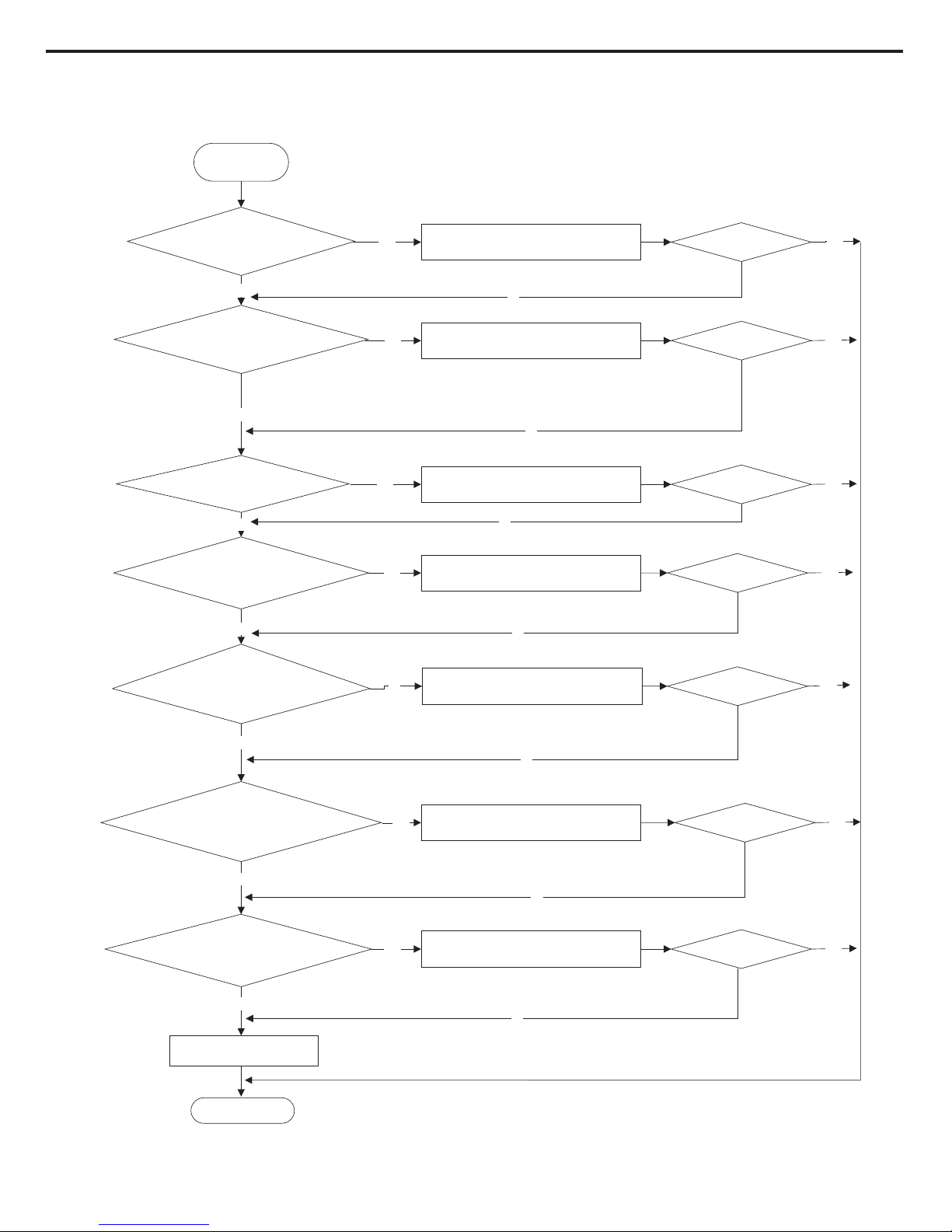
Service Manual
4.
Malfunction of Overcurrent Protection (E5)
no
no
no
no
yes
no
no
End
yes
Malfunction is
eliminated
Is the supply voltage unstable
with big fluctuation?
Is the supply voltage too low
with overload?
The fan is abnormal? Fan
speed is too low or fan doesn’t rotate
Measure the
current of live wireon the main
board with a clamp ampere meter. Is the
current higher than the value of the
overcurrent protection?
Is there blockage inside
the system? (Filth blockage, ice plug,
greasy blockage, the Y-valve hasn’t been opened
completely)
Is the compressor running
abnormally? Is there abnormal sound or oil
leakage; is the temperature of the shell
too high, etc.?
Is the indoor / outdoor
heat exchanger too dirty,or are the air inlet
and outlet blocked?
Normal fluctuation is within 10 % of the rated
voltage on the nameplate
Malfunction is
eliminated
.
no
yes
.
no
yes
.
no
yes
no
no
no
yes
no
yes
.
no
yes
yes
yes
yes
yes
yes
yes
Malfunction is
eliminated
Malfunction is
eliminated
Malfunction is
eliminated
Malfunction is
eliminated
Malfunction is
eliminated
Malfunction is
eliminated
Troubleshooting
for E5 malfunction
Adjust the supply voltage to maintain it within
normal range
Clean the indoor and outdoor heat exchangers
and remove the blockage of air inlet and outlet
Check the motor and reinstall the motor to have
the fan run normally
Replace the mainboard with the same model
Replace the mainboard with the same model
Flush the heat exchangers with high pressure
nitrogen
Replace the mainboard with
the same model
49

Service Manual
Possible Causes Discriminating Method (Air conditioner Status) Troubleshooting
Set temperature is improper Observe the set temperature on remote controller Adjust the set temperature
Rotation speed of the IDU fan
motor is set too low
Small wind blow Set the fan speed at high or medium
Filter of indoor unit is blocked Check the lter to see it's blocked Clean the lter
Installation position for indoor unit
and outdoor unit is improper
Check whether the installation postion is proper
according to installation requirement for air
conditioner
Adjust the installation position, and install the
rainproof and sunproof for outdoor unit
Refrigerant is leaking
Discharged air temperature during cooling is
higher than normal discharged wind temperature;
Discharged air temperature during heating is
lower than normal discharged wind temperature;
Unit's pressure is much lower than regulated
range
Find out the leakage causes and deal with it.
Add refrigerant.
Malfunction of 4-way valve Blow cold wind during heating Replace the 4-way valve
Malfunction of capillary
Discharged air temperature during cooling is
higher than normal discharged wind temperature;
Discharged air temperature during heating is
lower than normal discharged wind temperature;
Unit't pressure is much lower than regulated
range. If refrigerant isn’t leaking, part of capillary
is blocked
Replace the capillary
Flow volume of valve is
insufcient
The pressure of valves is much lower than that
stated in the specication
Open the valve completely
Malfunction of horizontal louver Horizontal louver can’t swing
Refer to point 3 of maintenance method for
details
Malfunction of the IDU fan motor The IDU fan motor can’t operate
Refer to troubleshooting for H6 for maintenance
method in details
Malfunction of the ODU fan motor The ODU fan motor can't operate
Refer to point 4 of maintenance method for
details
Malfunction of compressor Compressor can't operate
Refer to point 5 of maintenance method for
details
9.3 Maintenance Method for Normal Malfunction
1. Air Conditioner Can't be Started Up
2. Poor Cooling (Heating) for Air Conditioner
3. Horizontal Louver Can't Swing
Possible Causes Discriminating Method (Air conditioner Status) Troubleshooting
No power supply, or poor
connection for power plug
After energization, operation indicator isn’t bright
and the buzzer can't give out sound
Conrm whether it's due to power failure. If yes,
wait for power recovery
. If not, check power
supply circuit and make sure the power plug is
connected well.
Wrong wire connection between
indoor unit and outdoor unit,
or poor connection for wiring
terminals
Under normal power supply circumstances,
operation indicator isn't bright after energization
Check the circuit according to circuit diagram
and connect wires correctly. Make sure all
wiring terminals are connected rmly
Electric leakage for air conditioner
After energization, room circuit breaker trips off at
once
Make sure the air conditioner is grounded
reliably
Make sure wires of air conditioner is connected
correctly
Check the wiring inside air conditioner. Check
whether the insulation layer of power cord is
damaged; if yes, place the power cord.
Model selection for air switch is
improper
After energization, air switch trips off Select proper air switch
Malfunction of remote controller
After energization, operation indicator is bright,
while no display on remote controller or buttons
have no action.
Replace batteries for remote controller
Repair or replace remote controller
Possible Causes Discriminating Method (Air conditioner Status) Troubleshooting
Wrong wire connection, or poor
connection
Check the wiring status according to circuit
diagram
Connect wires according to wiring diagram to
make sure all wiring terminals are connected
rmly
Stepping motor is damaged Stepping motor can't operate Repair or replace stepping motor
Main board is damaged
Others are all normal, while horizontal louver
can't operate
Replace the main board with the same model
50
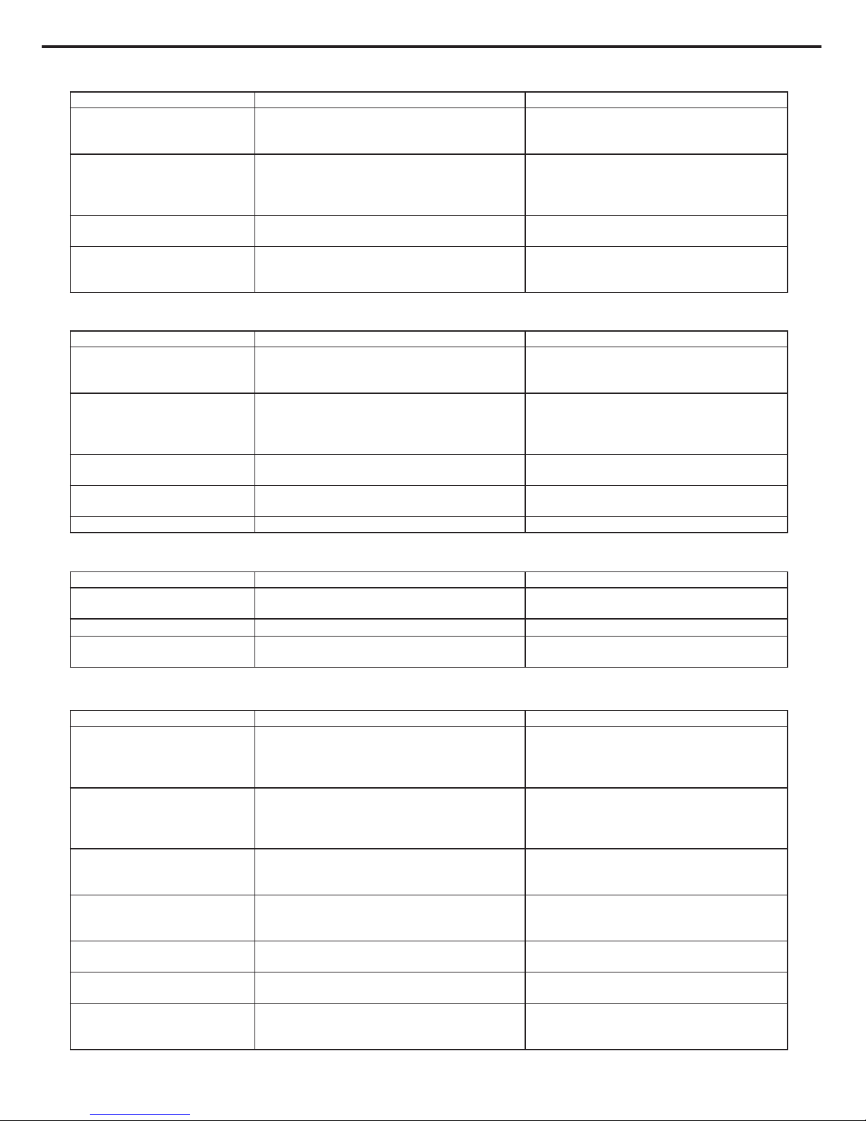
Service Manual
7. Abnormal Sound and Vibration
Possible causes Discriminating method (air conditioner status) Troubleshooting
When turn on or turn off the unit,
the panel and other parts will
expand and there's abnormal
sound
There's the sound of "P
APA"
Normal phenomenon. Abnormal sound will
disappear after a few minutes.
When turn on or turn off the unit,
there's abnormal sound due
to ow of refrigerant inside air
conditioner
Water-running sound can be heard
Normal phenomenon. Abnormal sound will
disappear after a few minutes.
Foreign objects inside the indoor
unit or there're parts touching
together inside the indoor unit
There's abnormal sound fro indoor unit
Remove foreign objects. Adjust all parts'
position of indoor unit, tighten screws and stick
damping plaster between connected parts
Foreign objects inside the outdoor
unit or there're parts touching
together inside the outdoor unit
There's abnormal sound fro outdoor unit
Remove foreign objects. Adjust all parts'
position of outdoor unit, tighten screws and
stick damping plaster between connected parts
Short circuit inside the magnetic
coil
During heating, the way valve has abnormal
electromagnetic sound
Replace magnetic coil
Abnormal shake of compressor Outdoor unit gives out abnormal sound
Adjust the support foot mat of compressor,
tighten the bolts
Abnormal sound inside the
compressor
Abnormal sound inside the compressor
If add too much refrigerant during maintenance,
please reduce refrigerant properly. Replace
compressor for other circumstances.
6. Air Conditioner is Leaking
Possible causes Discriminating method (air conditioner status) Troubleshooting
Drain pipe is blocked Water leaking from indoor unit
Eliminate
the foreign objects inside the drain
pipe
Drain pipe is broken Water leaking from drain pipe Replace drain pipe
Wrapping is not tight
Water leaking from the pipe connection place of
indoor unit
Wrap it again and bundle it tightly
5. Compressor Can't Operate
Possible causes Discriminating method (air conditioner status) Troubleshooting
Wrong wire connection, or poor
connection
Check the wiring status according to circuit
diagram
Connect wires according to wiring diagram to
make sure all wiring terminals are connected
rmly
Capacity of compressor is
damaged
Measure the capacity of fan capacitor with an
universal meter and nd that the capacity is out of
the deviation range indicated on the nameplate of
fan capacitor.
Replace the compressor capacitor
Power voltage is a little low or
high
Use universal meter to measure the power supply
voltage. The voltage is a little high or low
Suggest to equip with voltage regulator
Coil of compressor is burnt out
Use universal meter to measure the resistance
between compressor terminals and it's 0
Repair or replace compressor
Cylinder of compressor is blocked Compressor can't operate Repair or replace compressor
4. ODU Fan Motor Can't Operate
Possible causes Discriminating method (air conditioner status) Troubleshooting
Wrong wire connection, or poor
connection
Check the wiring status according to circuit
diagram
Connect wires according to wiring diagram to
make sure all wiring terminals are connected
rmly
Capacity of the ODU fan motor is
damaged
Measure the capacity of fan capacitor with an
universal meter and nd that the capacity is out of
the deviation range indicated on the nameplate of
fan capacitor.
Replace the capacity of fan
Power voltage is a little low or
high
Use universal meter to measure the power supply
voltage. The voltage is a little high or low
Suggest to equip with voltage regulator
Motor of outdoor unit is damaged
When unit is on, cooling/heating performance
is bad and ODU compressor generates a lot of
noise and heat.
Change compressor oil and refrigerant. If no
better, replace the compressor with a new one
51

Service Manual
10. Exploded View and Parts List
10.1 Indoor Unit
The component picture is only for reference; please refer to the actual product.
819
42322212826263534333231303
12 34 51213206 7181
7252
157
37
169101411
29
38
MUCO-48-H6T
MUCO-60-H6T
52

Service Manual
Above data is subject to change without notice.
No.
Description
Part Code
Qty
Product Code
1 Rear
Plate Assy 01304500 1
2 Left Side Plate Sub-Assy 0130451901 1
3 Right Side Plate Sub-Assy 0130451801 1
4
Top Cover Sub-Assy 22244152 1
5 Breakwater Sub-Assy 01364154P 1
6 Evaporator Assy 0100427201 1
7 Capillary Sub-assy (Heating) 03004012 1
8 Ambient Temperature Sensor 3900019003 1
9 Crank 73014023 1
10 Rear Grill 01474057 1
11 Electric Heater 32004124 1
12 Step Motor 1521400803 1
13 Step Motor 1521401601 1
14 Swing Lever 10584218 1
15 Guide Blade Lever 10584089 1
16 Display Board 30563195 1
17 Propeller HousingPress Plate Sub-assy 01384061 1
18 Air Guard Assy 01364509 1
19 Latch 70810302 1
20 Air Outlet Panel Assy 008014000020 1
21 Air Intake Panel Assy 20004536 1
22 Filter Sub-Assy 11124100 1
23 Electric Box Cover Sub-Assy 01404388 1
24 Main Board 300002000040 1
25 Capacitor CBB61 / /
26 Terminal Board 42010052 1
27 Transformer 43110287 1
28 Electric Box Assy 100002000367 1
29 Protective Covering 01474027 1
30 Diversion Circle 10374435 1
31 Propeller Housing Sub-assy 12104058 1
32 Centrifugal Fan 10314401 1
33 Fan Motor 1501442502 1
34 Chassis 22224020 1
35 Water Tray Sub-Assy 12314811 1
36 Bafe Plate 2611454401 3
37 Rear Cover 2224422201 3
38 Connecting Cable 4002053910 1
MUCO-48-H6T
UI20390
53
Service Manual
Above data is subject to change without notice.
No.
Description
Part Code
Qty
Product Code
1 Rear
Plate Assy 01304500 1
2 Left Side Plate Sub-Assy 0130451901 1
3 Right Side Plate Sub-Assy 0130451801 1
4
Top Cover Sub-Assy 22244152 1
5 Breakwater Sub-Assy 01364503P 1
6 Evaporator Assy 011001000168 1
7 Capillary Sub-assy (Heating) 030006000230 1
8 Ambient Temperature Sensor 3900019003 1
9 Crank 73014023 1
10 Rear Grill 01474057 1
11 Electric Heater 32004124 1
12 Step Motor 1521401601 1
13 Step Motor 1521400803 1
14 Swing Lever 10584218 1
15 Guide Blade Lever 10584089 1
16 Display Board 30563195 1
17 Propeller HousingPress Plate Sub-assy 01384061 1
18 Air Guard Assy 01364509 1
19 Latch 70810302 1
20 Air Outlet Panel Assy 008014000020 1
21 Air Intake Panel Assy 20004536 1
22 Filter Sub-Assy 11124100 1
23 Electric Box Cover Sub-Assy 01404388 1
24 Main Board 300002000040 1
25 Capacitor CBB61 / 1
26 Terminal Board 42010052 1
27 Transformer 43110287 1
28 Electric Box Assy 100002000367 1
29 Protective Covering 01474027 1
30 Diversion Circle 10374435 1
31 Propeller Housing Sub-assy 12104058 1
32 Centrifugal Fan 10314401 1
33 Fan Motor 1501442502 1
34 Chassis 22224020 1
35 Water Tray Sub-Assy 12314811 1
36 Bafe Plate 2611454401 3
37 Rear Cover 2224422201 3
38 Connecting Cable 400205396 1
MUCO-60-H6T
UI20391
54

Service Manual
10.2 Outdoor Unit
The component picture is only for reference; please refer to the actual product.
2
3
4 5 1413
11
10
20
18
23
3437
12
16
22
38
24
26
31
32
33
30
29
28
27
25
36 35
21
19
15
17
1
768 9
MUCO-48-H6T
55
Service Manual
Above data is subject to change without notice.
No.
Description
Part Code
Qty
Product Code
1 Front Grill 01475401 1
2 Left Handle 26235401 1
3 Cabinet 01435103P
1
4 Axial Flow Fan 10335401 1
5 Fan Motor 15010100000101 1
6 Motor Support 01705401 1
7 Ambient T
emperature Sensor 39000199 1
8 Sensor Support 24215101 1
9 Condenser Assy 011002000212 1
10 Coping 01255012P 1
11 Clapboard Sub-Assy 01235403 1
12 Rear Grill 01473003 1
13 Rear Side Plate Sub-Assy 01303290 1
14 Outdoor Tube Sensor 39000194 1
15 Handle 26235253 2
16 Assistant Capillary Sub-Assy 03133489 1
17 4-Way Valve Assy 030152000131 1
18 Magnet Coil 4300040022 1
19 Pressure Protect Switch 4602000603 1
20 Inhalation Tube Assy 03735085 1
21 Pressure Protect Switch 46020007 1
22 Air-out Temp Sensor 39000163 1
23 Cut off Valve Sub-Assy 07130212 1
24 Valve Support Sub-Assy 01715402 1
25 Gas Valve Sub-Assy / /
26 Compressor and Fittings 00105065 1
27 Capacitor CBB61 3301074705 1
28 Terminal Board 42010052 2
29 Over Current Protector 46020112 1
30 Terminal Board 42011103 2
31 Anti-phase Protector 46020052 1
32 AC Contactor 44010226 1
33 Electric Box Assy 100002000129 1
34 Chassis Sub-assy 012054026P 1
35 Drainage Connecter 06123401 1
36 Drainage Hole Cap 06813401 2
37 Front Side Plate Sub-Assy 01305507 1
38 Electrical Heater 7651540413 1
MUCO-48-H6T
UE20390
56
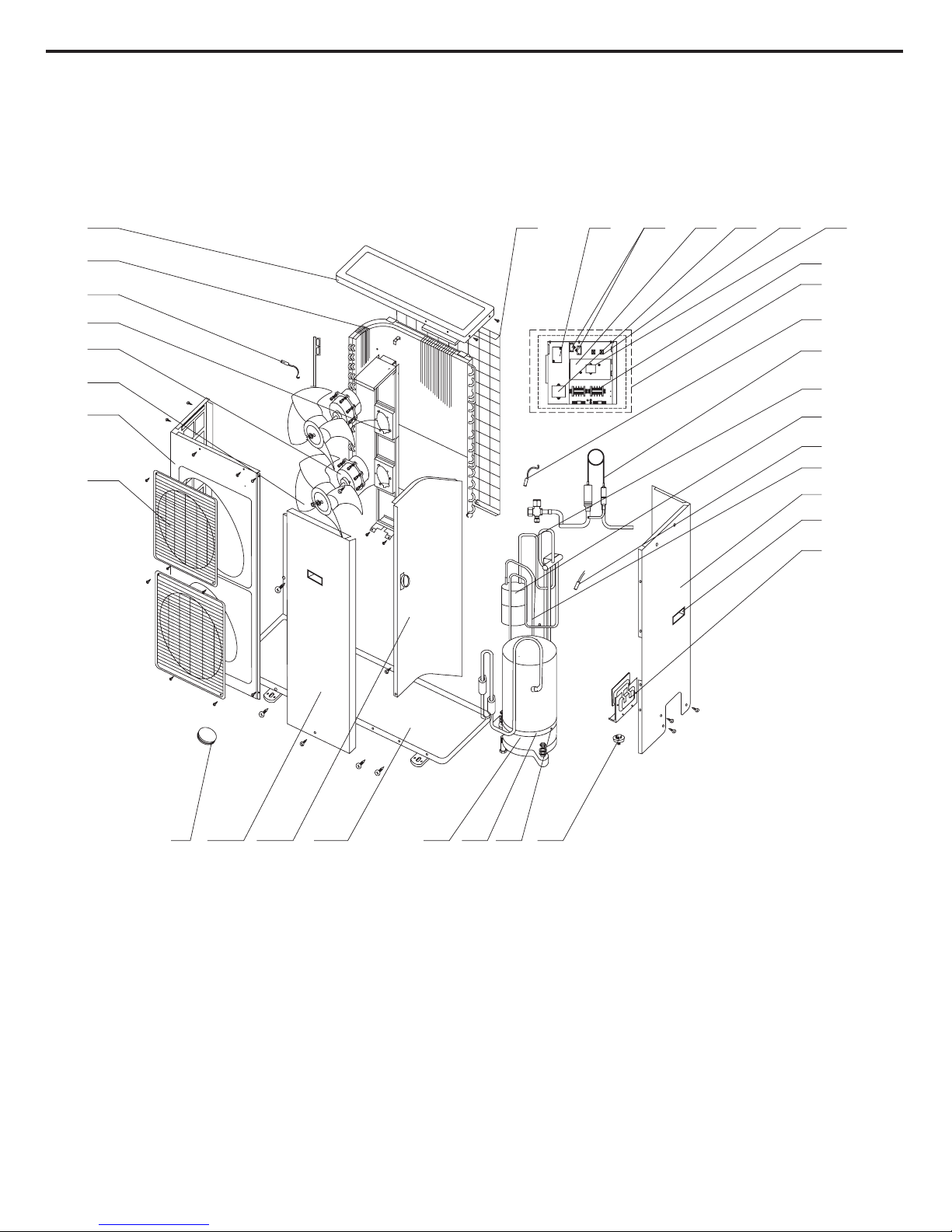
Service Manual
MUCO-60-H6T
The component picture is only for reference; please refer to the actual product.
27
13
1
2
3
4
5
8
91112
14
10
33 32 31
30
23
25
24
26
20
15
19
21
22
18
17
7
6
29 2834
16
57

Service Manual
Above data is subject to change without notice.
No.
Description
Part Code
Qty
Product Code
1 Front grill 01473001 2
2 Cabinet 0143543601 1
3 Axial Flow Fan 10434100004 2
4 Fan Motor 1501506715 2
5 Motor Support Sub-Assy 01705070 1
6 Ambient T
emperature Sensor 39000199 1
7 Condenser
Assy 01105734 1
8 Top Cover 01255013P 1
9 Rear Grill 01475006 1
10 AC Contactor 44010226 1
11 Capacitor CBB61 3301074705 2
12 Over Current Protector 46020112 1
13 Phase Reverse Protector 46020052 1
14 Terminal Board 42010052 2
15 Terminal Board 42010052 2
16 Transformer 43110325 1
17 Electric Box Assy 100002000518 1
18 Outdoor Tube Sensor / 1
19 Capillary Sub-assy 030036000003 1
20 4-Way Valve Assy 030152000162 1
21 Gas-liquid Separator Sub-Assy 07225016 1
22 Air-out Temp Sensor 39000163 1
23 Inhalation tube Assy 03001000271 1
24 Rear Side Plate Sub-Assy 01305102 1
25 Handle 26235253 3
26 Valve Support Sub-Assy 01715001 1
27 Drainage Connecter 06123401 1
28 Terminal Board 42010052 2
29 Electric Heater(Compressor) 7651540410 1
30 Compressor and Fittings 00105066 1
31 Chassis Sub-assy 0120543311P 1
32 Clapboard Sub-Assy 0124526201 1
33 Front Side Plate 01305431 1
34 Drainage Plug 06813401 3
MUCO-60-H6T
UE20391
58

Service Manual
11. Removal Procedure
11.1 Removal Procedure of Indoor Unit
Caution: discharge the refrigerant completely before removal.
Steps Procedure
1. Remove air-inlet panel
Remove the screw stopper;remove the
screws fixing air-inlet panel and pull the
upper part of air-inlet panel outwards.
2. Remove air-outlet panel
Remove the screws fixing the top and
lower part of air-outlet panel; push the
air-outlet panel upwards slightly and
then remove the air-outlet panel.
screw
air-inlet panel
air-outlet panel
59

Service Manual
Steps Procedure
3. Remove displayboard, horizontal
swing motor and vertical swing motor
Remove the screws fixing controller box;
remove the controller box cover to
remove the displayboard; remove the
screw fixing motor in the air-outlet panel
sub-assy; remove the horizontal swing
motor and vertical swing motor.
4. Remove air guard
Remove the screw fixing air guard and
then remove the air guard.
display board
step motors
air guard
60

Service Manual
Steps Procedure
5. Remove electric box assy
Remove the screw fixing electric box
cover to remove the electric box cover;
disconnect each wiring terminal; remove
the relevant electrical elements
according to the requirement; remove
the screw fixing electric box to remove
the electric box assy.
air guard
electric box cover
61

Service Manual
Steps Procedure
6. Remove top cover
Remove the screw fixing top cover to
remove the top cover.
7. Remove evaporator assy
Remove the screws fixing the top connection
plate and lower connection plate of
evaporator; pull the left side plate and right
side plate outwards slightly to remove the
evaporator, water guard and water tray; after
removing the evaporator, remove the left and
right air guard and water guard at the top side
of evaporator.
top cover
evaporator
water tray
water guard
62

Service Manual
Steps Procedure
8. Remove propeller housingclamp
Remove the screws fixing propeller housing
clamp and then pull the propeller housing
clamp outwards to remove the propeller
housing clamp.
9. Remove propeller housingsub-assy
Remove the screws fixing propeller housing
to remove the propeller housing sub-assy.
propeller housing clamp
propeller housing sub-assy
63

Service Manual
Steps Procedure
10. Remove centrifugal blade
Remove the nut fixing centrifugal blade to
remove the centrifugal blade.
11. Remove motor
Remove the remove the wire clamp on the
rear plate; disconnect the motor wire and
remove the screws fixing motor to remove
the motor.
centrifugal blade
nut
motor
64
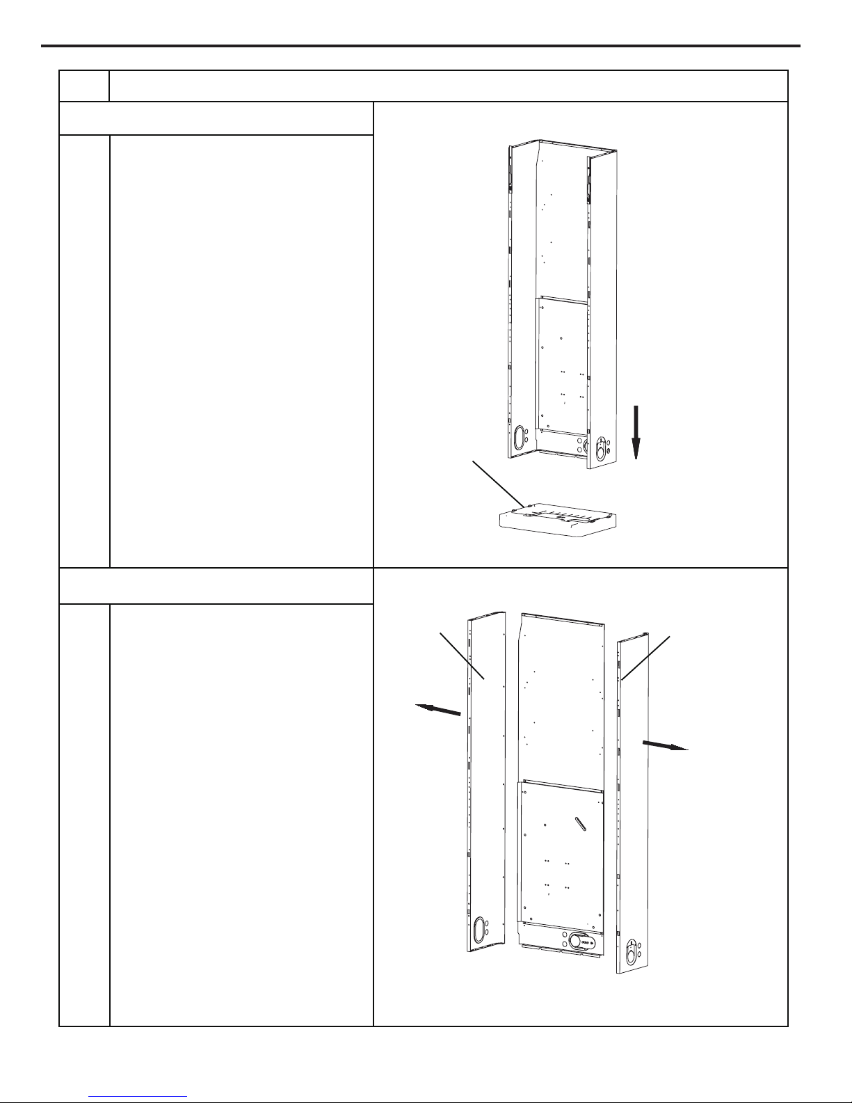
Service Manual
Steps Procedure
12. Remove chassis
Remove the screws fixing chassis to remove
the chassis.
13. Remove left side plate and right side plate
Remove the screws fixing left side plate and
right side plate to remove the left side plate
and right side plate sub-assy.
chassis
left side plate
right side plate
65

Service Manual
11.2 Removal Procedure of Outdoor Unit
top panel
front side plate
3.Remove front side plate
1.Before disassembly of unit
2.Remove top panel
Twist off the screws used for fixing the top cover
with screwdriver, lift up the top cover and then
remove the top cover.
Twist off the screws used for fixing the front side
plate, pull the front side plate forward and
outward and then remove the front side plate.
StepProcedure
MUCO-48-H6T
66

Service Manual
ProcedureStep
guard grille
grille
panel
4.Remove guard grille
5.Remove grille
6.Remove panel
Twist off the screws used for fixing the guard
grille, pull the guard grille outward and then
remove the guard grille.
Twist off the screw used for fixing the grille,
loosen the clasp, pull out the grille outward and
then remove the grille.
Twist off the screw used for fixing the outer case,
pull the panel outwardand then remove the panel.
67
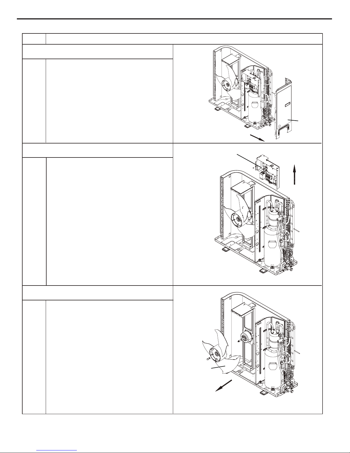
Service Manual
erudecorPpetS
right side
plate
electric box
axial flow blade
7.Remove right side plate
8.Remove electric box
9.Remove axial flowblade
Twist off the nuts used for fixing the axial flow
blade, pull the axial flowblade outwardand then
remove the blade.
Cut off the tieline, pull out the wiring terminal,
remove all the connecting wires, twist off the
screws used for fixing the electric box, pull it
upward and then remove the electric box.
Twist off the screw used for fixing the right side
plate and then pull the right side plate outward.
68
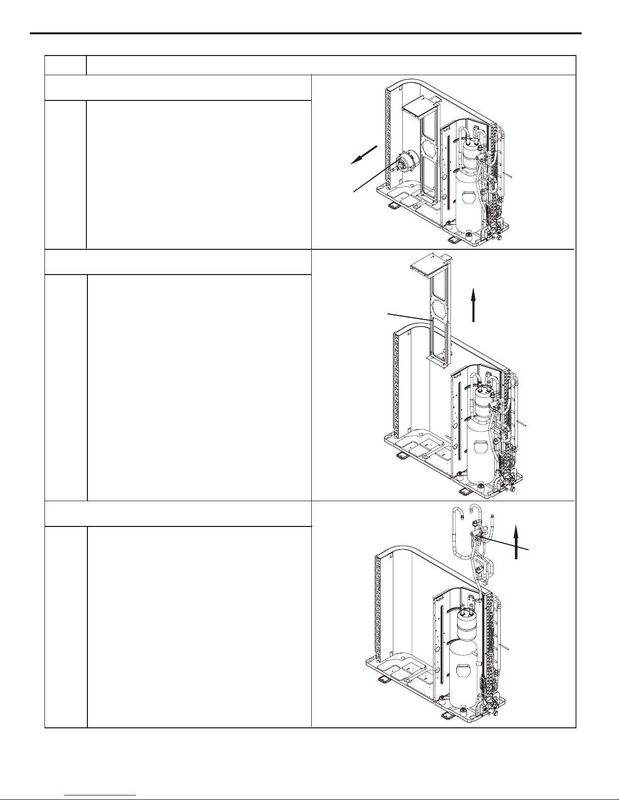
Service Manual
erudecorPpetS
motor
motor support
four-way valve
10.Remove motor
11.Remove motor support
12.Remove four-way valve and air intake pipe
Twist off the screws used for fixing the motor,
pull out the motor wire and pull it outward,then
remove the motor.
Twist off the screws used for fixing the motor
support, pull it upward and then remove the
motor support.
Release the refrigerant completely, unsolder the
air intake pipe of compressor, outlet pipe of
condenser, connecting pipe of gas valve and
gas and liquid separator, then pull the four-way
valve and air intake pipe.
69

Service Manual
Step
Procedure
gas and liquid seperator
compressor
isolation sheet
13.Remove gas and liquid separator
14.Remove compressor
15.Remove middle isolation sheet
Loosen the two screws used for fixing the gas
and liquid separator, pull it upward and then
remove the gas and liquid separator.
Twist off the nuts used for fixing the compressor
withwrench, pull the compressor upward to
remove it.
Twist off the screws used for fixing the middle
isolation sheet, pull it upward and then remove
the isolation sheet.
70

Service Manual
Step
Procedure
16.Remove condenser and capillary
condenser
capillary
17.Remove gas valve and valve support
valve support
gas valve
Twist off thescrews used for fixing the condenser,
unsolder the spot weld between capillary and
condenser (notice: before soldering, the refrigerant
should be released completely), pull it outward
and then remove the condenser and capillary.
Twist off the bolts used for fixing the gas valve
and valve support, and thenremove the gas
valve;
Twist off the screws used for connecting the
valve support and chassis, pull it upward and
then remove thevalve support.
71

Service Manual
1. Remove the
Steps Procedure
rear grille
Remove the tapping screws connecting the
back grille with the back-side plate, the front
case and the chassis. Remove the back
grille.
2. Remove the top cover
Remove the screws fixing the top cover.
Raise the top cover to remove it.
3. Remove the
front side plate
Remove the 3 tapping screws fixing the
front side plate. Take the front side plate
outward to remove it.
front side plate
top cover
screws
screws
rear grille
MUCO-60-H6T
72
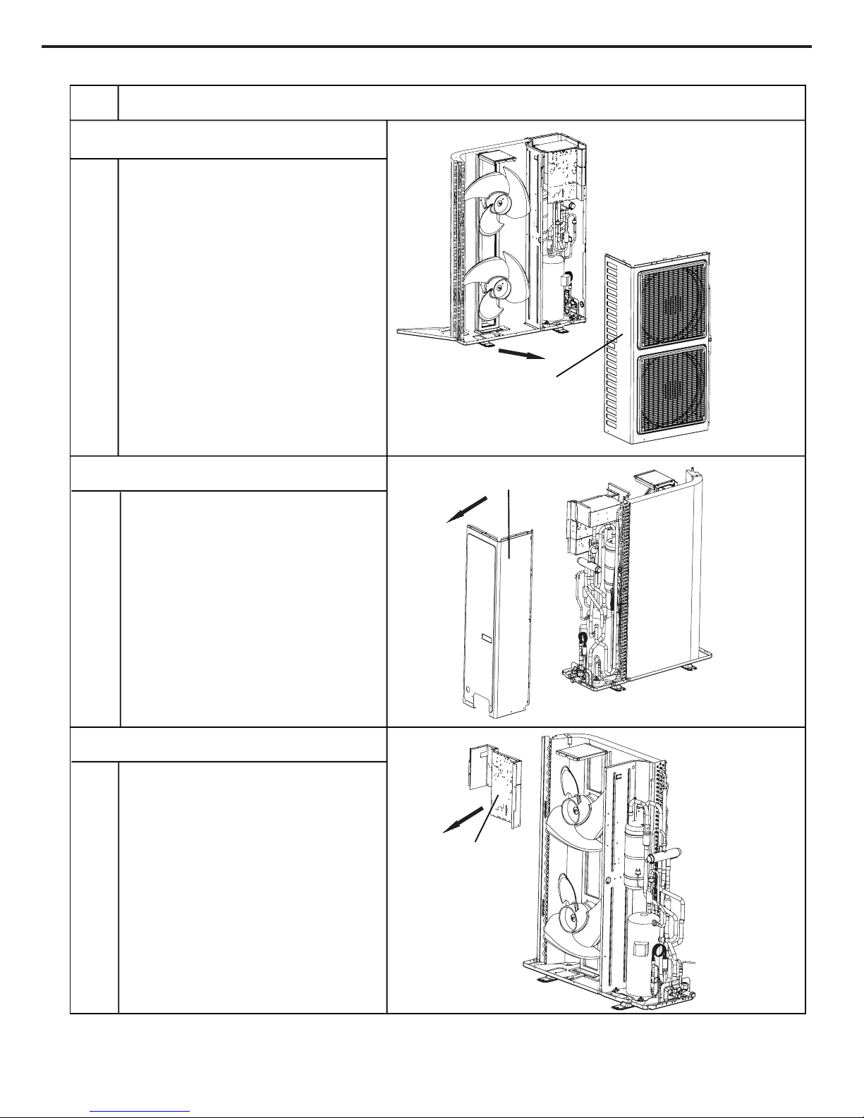
Service Manual
4. Remove the cabinet
Remove the connecting screws fixing the
cabinet. Remove the cabinet.
5. Remove
right side plate subassembly
Remove the screws fixing the right side plate.
Remove the right side plate.
6. Remove electric box subassembly
Remove the screws fixing the electric box
cover. Disconnect the wire terminals and
remove the electric box.
electric box subassembly
right side plate
cabinet
Steps Procedure
73

Service Manual
7. Remove axial flow blades
Remove the nut on the axial flow blades.
Remove the blades.
8. Remove the motors
Remove the 4 screws fixing the motors.
Disconnect the leading wire inserts of the
motors. Remove the motors.
9. Remove the motor support
Remove the screws connecting the motor
support and the chassis. Raise the motor
support to remove it.
motor support
motors
axial flow blades
Steps Procedure
74

Service Manual
10. Remove the 4-way valve
(Only available for heat pump unit)
Remove the nut on the 4-way valve coil and
then remove the coil. Wrap the 4-way valve
with a wet cloth. Unsolder the 4-way valve
quickly and remove it. Ensure that the cloth
keeps wet and do not burn the compressor
lead. (Recover the refrigerant before
unsoldering)
11. Remove the compressor
Unsolder the pipes connected to the
compressor and
liquid tank. Remove the 4
foot bolts of the compressor. Raise the liquid
tank and compressor to remove them.
compressor
liquid tank
4-way valve
Steps Procedure
75

Service Manual
12. Remove the valve
Remove the 2 bolts fixing the gas valve.
Unsolder the welding joint between the gas
valve and the return air pipe. Remove the
gas valve. Remove the 2 bolts fixing the
liquid valve. Unsolder the welding joint
between the liquid valve and the Y- type
connecting pipe. Remove the liquid valve.
(Note: During unsoldering, wrap the gas
valve with a wet cloth to avoid damage to the
valve caused by high temperature.)
13. Remove the isolation sheet
Remove the screws connecting the isolation
sheet with the right side plate of condenser
and the chassis. Remove the isolation sheet.
isolation sheet
valve
Steps Procedure
76

Service Manual
14. Remove condenser subassembly
Remove the screws connecting the
condenser and the chassis. Raise the
condenser subassembly to remove it.
15. Remove valve support subassembly
Remove the screw connecting the valve
support and the chassis. Remove the valve
support subassembly.
valve support subassembly
condenser
subassembly
Steps Procedure
77

Service Manual
Appendix:
1.Standard length of connection pipe
● 5m, 7.5m, 8m.
2.Min. length of connection pipe is 3m.
3.Max. length of connection pipe and max. high difference.
4.The additional
refrigerant oil and refrigerant charging required after
prolonging connection pipe
● After the length of connection pipe is prolonged for 10m at the basis
of standard length, you should add 5ml of refrigerant oil for each
additional 5m of connection pipe.
● The calculation method of additional refrigerant charging amount (on
the basis of liquid pipe):
Appendix 1: Reference Sheet of Celsius and Fahrenheit
Appendix 2: Conguration of Connection Pipe
Cooling capacity
Max length of
connection pipe
Max height
dif
ference
5000 Btu/h(1465 W) 15 m 5 m
7000 Btu/h(2051 W) 15 m 5 m
9000 Btu/h(2637 W) 15 m 10 m
12000 Btu/h(3516 W) 20 m 10 m
18000 Btu/h(5274 W) 25 m 10 m
24000 Btu/h(7032 W) 25 m 10 m
28000 Btu/h(8204 W) 30 m 10 m
36000 Btu/h(10548 W) 30 m 20 m
42000 Btu/h(12306 W) 30 m 20 m
48000 Btu/h(14064 W) 30 m 20 m
Set temperature
Conversion formula for Fahrenheit degree and Celsius degree: Tf=Tcx1
.8+32
Ambient temperature
Fahrenheit
display
temperature
(℉)
Fahrenheit
(℉)
Celsius
(℃)
Fahrenheit
display
temperature
(℉)
Fahrenheit
(℉)
Celsius
(℃)
Fahrenheit
display
temperature
(℉)
Fahrenheit
(℉)
Celsius
(℃)
32/33 32 0 55/56 55.4 13 79/80 78.8 26
34/35 33.8 1 57/58 57.2 14 81 80.6 27
36 35.6 2 59/60 59 15 82/83 82.4 28
37/38 37.4 3 61/62 60.8 16 84/85 84.2 29
39/40 39.2 4 63 62.6 17 86/87 86 30
41/42 41 5 64/65 64.4 18 88/89 87.8 31
43/44 42.8 6 66/67 66.2 19 90 89.6 32
45 44.6 7 68/69 68 20 91/92 91.4 33
46/47 46.4 8 70/71 69.8 21 93/94 93.2 34
48/49 48.2 9 72 71.6 22 95/96 95 35
50/51 50 10 73/74 73.4 23 97/98 96.8 36
52/53 51.8 11 75/76 75.2 24 99 98.6 37
54 53.6
12 77/78 77 25
Fahrenheit
display
temperature
(℉)
Fahrenheit
(℉)
Celsius
(℃)
Fahrenheit
display
temperature
(℉)
Fahrenheit
(℉)
Celsius
(℃)
Fahrenheit
display
temperature
(℉)
Fahrenheit
(℉)
Celsius
(℃)
61 60.8 16 69/70 69.8 21 78/79 78.8 26
62/63 62.6 17 71/72 71.6 22 80/81 80.6 27
64/65 64.4 18 73/74 73.4 23 82/83 82.4 28
66/67 66.2 19 75/76 75.2 24 84/85 84.2 29
68 68 20 77 77 25 86 86 30
Additional refrigerant charging amount for R22, R407C, R410A and R134a
Diameter of connection pipe Outdoor unit throttle
Liquid pipe(mm) Gas pipe(mm) Cooling only(g/m) Cooling and heating(g/m)
Ф6 Ф9.5 or Ф12 15 20
Ф6 or Ф9.5 Ф16 or Ф19 15 20
Ф12 Ф19 or Ф22.2 30 120
Ф16 Ф25.4 or Ф31.8 60 120
Ф19 / 250 250
Ф22.2 / 350 350
● When
the length of connection pipe is above 5m, add refrigerant according to the prolonged length of liquid pipe. The additional
refrigerant charging amount per meter is different according to the diameter of liquid pipe. See the following sheet.
● Additional refrigerant charging amount = prolonged length of liquid pipe X additional refrigerant charging amount per meter
78

Service Manual
F:Inspection
● Check the
quality of expanding port. If there is any blemish, expand the
port again according to the steps above.
The length is equal
Improper expanding
leaning
damaged
surface
crack uneven
thickness
Smooth surface
Downwards
Pipe
Shaper
Union pipe
Pipe
Expander
Hard
mold
Pipe
Pipe
Pipe cutter
Leaning Uneven Burr
Improper
pipe
expanding
is the main cause of refrigerant leakage.Please
expand the pipe according to the following steps:
A:Cut the pip
● Conrm the pipe length according to the distance of indoor unit and outdoor unit.
● Cut the required pipe with pipe cutter.
B:Remove the burrs
● Remove the burrs with shaper and prevent the burrs from getting into the pipe.
C:Put on suitable insulating pipe
D:Put on the union nut
● Remove the union nut on the indoor connection pipe and outdoor valve; install
the union nut on the pipe.
E:Expand the port
● Expand the port with expander.
● "A" is different according to the diameter, please refer to the sheet below:
Outer diameter(mm)
A(mm)
Max Min
Ф6 - 6.35 (1/4") 1.3 0.7
Ф9.52 (3/8”) 1.6 1.0
Ф12 - 12.70 (1/2”) 1.8 1.0
Ф16 - 15.88 (5/8”) 2.4 2.2
Appendix 3: Pipe Expanding Method
Note:
Note:
79
Service Manual
Appendix 4: List of Resistance for Temperature Sensor
Resistance Table of Ambient T
emperature Sensor for Indoor and Outdoor Units(15K)
T
emp(
o
C) Resistance(kΩ) T
emp(
o
C) Resistance(kΩ) T
emp(
o
C) Resistance(kΩ) T
emp(
o
C) Resistance(kΩ)
-19 138.1 20 18.75 59 3.848 98 1.071
-18 128.6 21 17.93 60 3.71
1 99 1.039
-17 121.6 22 17.14 61 3.579 100 1.009
-16 11
5 23 16.39 62 3.454 101 0.98
-15 108.7 24 15.68 63 3.333 102 0.952
-14 102.9 25 15 64 3.217 103 0.925
-13 97.4 26 14.36 65 3.105 104 0.898
-12 92.22 27 13.74 66 2.998 105 0.873
-
11 87.35 28 13.16 67 2.896 106 0.848
-10 82.75 29 12.6 68 2.797 107 0.825
-9 78.43 30 12.07 69 2.702 108 0.802
-8 74.35 31 11.57 70 2.611 109 0.779
-7 70.5 32 11.09 71 2.523 110 0.758
-6 66.88 33 10.63 72 2.439 111 0.737
-5 63.46 34 10.2 73 2.358
112 0.717
-4 60.23 35 9.779 74 2.28 113 0.697
-3 57.18 36 9.382 75 2.206 11
4 0.678
-2 54.31 37 9.003 76 2.133 11 5 0.66
-1 51.59 38 8.642 77 2.064 11 6 0.642
0 49.02 39 8.297 78 1.997 117 0.625
1 46.6 40 7.967 79 1.933 118 0.608
2 44.31 41 7.653 80 1.871 119 0.592
3 42.14 42 7.352 81 1.811 120 0.577
4 40.09 43 7.065 82 1.754 121 0.561
5 38.15 44 6.791 83 1.699 122 0.547
6 36.32 45 6.529 84 1.645 123 0.532
7 34.58 46 6.278 85 1.594 124 0.519
8 32.94 47 6.038 86 1.544 125 0.505
9 31.38 48 5.809 87 1.497 126 0.492
10 29.9 49 5.589 88 1.451 127 0.48
11 28.51 50 5.379 89 1.408 128 0.467
12 27.18 51 5.197
90 1.363 129 0.456
13 25.92 52 4.986 91 1.322 130 0.444
14 24.73 53 4.802 92 1.282 131 0.433
15 23.6 54 4.625 93 1.244 132 0.422
16 22.53 55 4.456 94 1.207 133 0.412
17 21.51 56 4.294 95 1.171 134 0.401
18 20.54 57 4.139 96 1.136 135 0.391
19 19.63 58 3.99 97 1.103 136 0.382
80

Service Manual
Resistance Table of Tube T
emperature Sensors for Indoor and Outdoor (20K)
Temp(oC) Resistance(kΩ) Temp(oC) Resistance(kΩ) Temp(oC) Resistance(kΩ) Temp(oC) Resistance(kΩ)
-19 181.4 20 25.01 59 5.13 98 1.427
-18 171.4 21 23.9 60 4.948 99 1.386
-17 162.1 22 22.85 61 4.773 100 1.346
-16 153.3 23 21.85 62 4.605 101 1.307
-15 145 24 20.9 63 4.443 102 1.269
-14 137.2 25 20 64 4.289 103 1.233
-13 129.9 26 19.14 65 4.14 104 1.198
-12 123 27 18.13 66 3.998 105 1.164
-
11 116.5 28 17.55 67 3.861 106 1.131
-10 1
10.3 29 16.8 68 3.729 107 1.099
-9 104.6 30 16.1 69 3.603 108 1.069
-8 99.13 31 15.43 70 3.481 109 1.039
-7 94 32 14.79 71 3.364 110 1.01
-6 89.17 33 14.18 72 3.252 111 0.983
-5 84.61 34 13.59 73 3.144
112 0.956
-4 80.31 35 13.04 74 3.04 113 0.93
-3 76.24 36 12.51 75 2.94 11
4 0.904
-2 72.41 37 12 76 2.844 11 5 0.88
-1 68.79 38 11.52 77 2.752 11 6 0.856
0 65.37 39 11.06 78 2.663 11 7 0.833
1 62.13 40 10.62 79 2.577 11 8 0.811
2 59.08 41 10.2 80 2.495 119 0.77
3 56.19 42 9.803 81 2.415 120 0.769
4 53.46 43 9.42 82 2.339 121 0.746
5 50.87 44 9.054 83 2.265 122 0.729
6 48.42 45 8.705 84 2.194 123 0.71
7 46.11 46 8.37 85 2.125 124 0.692
8 43.92 47 8.051 86 2.059 125 0.674
9 41.84 48 7.745 87 1.996 126 0.658
10 39.87 49 7.453 88 1.934 127 0.64
11 38.01 50 7.173 89 1.875 128 0.623
12 36.24 51 6.905
90 1.818 129 0.607
13 34.57 52 6.648 91 1.736 130 0.592
14 32.98 53 6.403 92 1.71 131 0.577
15 31.47 54 6.167 93 1.658 132 0.563
16 30.04 55 5.942 94 1.609 133 0.549
17 28.68 56 5.726 95 1.561 134 0.535
18 27.39 57 5.519 96 1.515 135 0.521
19 26.17 58 5.32 97 1.47 136 0.509
81
Service Manual
Resistance Table of Discharge Temperature Sensor for Outdoor(50K)
Temp(oC) Resistance(kΩ) Temp(oC) Resistance(kΩ) Temp(oC) Resistance(kΩ) Temp(oC) Resistance(kΩ)
-29 853.5 10 98 49 18.34 88 4.75
-28 799.8 11 93.42 50 17.65 89 4.61
-27 750 12 89.07 51 16.99 90 4.47
-26 703.8 13 84.95 52 16.36 91 4.33
-25 660.8 14 81.05 53 15.75 92 4.20
-24 620.8 15 77.35 54 15.17 93 4.08
-23 580.6 16 73.83 55 14.62 94 3.96
-22 548.9 17 70.5 56 14.09 95 3.84
-21 516.6 18 67.34 57 13.58 96 3.73
-20 486.5 19 64.33 58 13.09 97 3.62
-19 458.3 20 61.48 59 12.62 98 3.51
-18 432 21 58.77 60 12.17 99 3.41
-17 407.4 22 56.19 61 1
1.74 100 3.32
-16 384.5 23 53.74 62 11.32 101 3.22
-15 362.9 24 51.41 63 10.93
102 3.13
-14 342.8 25 49.19 64 10.54 103 3.04
-13 323.9 26 47.08 65 10.18 104 2.96
-12 306.2 27 45.07 66 9.83 105 2.87
-
11 289.6 28 43.16 67 9.49 106 2.79
-10 274 29 41.34 68 9.17 107 2.72
-9 259.3 30 39.61 69 8.85 108 2.64
-8 245.6 31 37.96 70 8.56 109 2.57
-7 232.6 32 36.38 71 8.27 11 0 2.50
-6 220.5 33 34.88 72 7.99 111 2.43
-5 209 34 33.45 73 7.73 11
2 2.37
-4 198.3 35 32.09 74 7.47 11 3 2.30
-3 199.1 36 30.79 75 7.22 11 4 2.24
-2 178.5 37 29.54 76 7.00 11 5 2.18
-1 169.5 38 28.36 77 6.76 11 6 2.12
0 161 39 27.23 78 6.54 117 2.07
1 153 40 26.15 79 6.33 118 2.02
2 145.4 41 25.11
80 6.13 11 9 1.96
3 138.3 42 24.13 81 5.93 120 1.91
4 131.5 43 23.19 82 5.75 121 1.86
5 125.1 44 22.29 83 5.57 122 1.82
6 119.1 45 21.43 84 5.39 123 1.77
7 1
13.4 46 20.6 85 5.22 124 1.73
8 108 47 19.81 86 5.06 125 1.68
9 102.8 48 19.06 87 4.90 126 1.64
82

ASK FOR MORE INFORMATION
Phone: (+34) 93 446 27 81
eMail: info@mundoclima.com
TECHNICAL ASSIST
ANCE
Phone: (+34) 93 652 53 57
www.mundoclima.com
 Loading...