

mundoclima H6M SERIE Service Manual
MULTI INVERTER SERIE H6M
Service manual
www.mundoclima.com
Th
ank you very much for purchasing our products.
Please read this manual carefully before installing
and using the unit.
CL20440 to CL20452
English

CONTENTS
1. General information of Outdoor Units .......................................... 3
2. Features ................................................................ .......................... 4
3. Dimensions ..................................................................................... 5
4. Refrigeration Cycle Diagram ......................................................... 6
5. Wiring diagram ............................................................................... 8
6. Indoor units combination ............................................................ 11
7. Sound Levels ................................................................................ 13
8. Installation Details ........................................................................ 14
8.1 Wrench torque sheet for installation .......................................................................................... 14
8.2 Connecting the cables ............................................................................................................... 14
8.3 Pipe length and the elevation .................................................................................................... 14
8.4 Installation for the first time ........................................................................................................ 15
8.5 Adding the refrigerant after running the system for many years ............................................... 19
8.6 Re-installation while the indoor unit need to be repaired .......................................................... 20
8.7 Re-installation while the outdoor unit need to be repaired ........................................................ 22
9. Electronic control function ........................................................ 24
10. Troubleshooting ........................................................................ 29

3
1. General information of Outdoor Units
Model name Dimension (mm) Compressor
MUEX-14-H6.2
MUEX-18-H6.2
MUEX-21-H6.3
MUEX-27-H6.3
MUEX-28-H6.4
MUEX-36-H6.4
MUEX-42-H6.5
800x333x554
800x333x554
845x363x702
845x363x702
946x410x810
946x410x810
946x410x810
ASN108D22UEZ
ASM135D23UFZ
ASM135D23UFZ
ATF235D22UMT
ATF235D22UMT
ATF310D43UMT
ATF310D43UMT
Outdoor unit
Discharge pipe temperature protection
4
2. Features
Power relay control
Low noise air flow system
Hydrophilic aluminum fin
The hydrophilic fin can improve the heating efficiency at operation mode.
4 way valve control
It is only operated in the heating operation mode except defrosting operation.
Anti-rust cabinet
Valve protection cover
It protects the valves and prevents water from dripping.
5
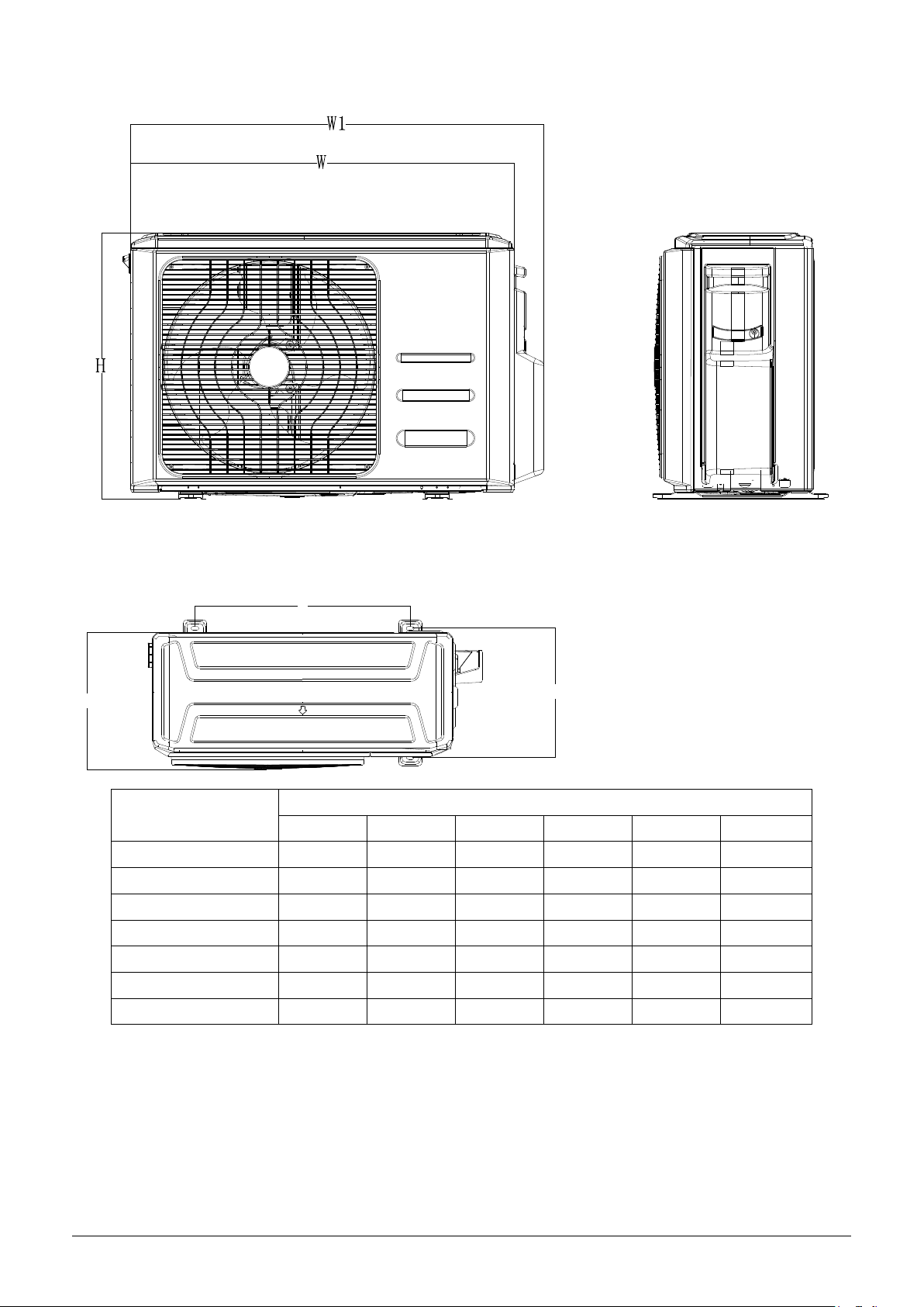
3. Dimensions
A
D
Model
W D H W1 A B
MUEX-14-H6.2 800 333 554 860 514 340
MUEX-18-H6.2 800 333 554 860 514 340
MUEX-21-H6.3 845 363 702 923 540 350
MUEX-27-H6.3 845 363 702 923 540 350
MUEX-28-H6.4 946 410 810 1034 673 403
MUEX-36-H6.4 946 410 810 1034 673 403
MUEX-42-H6.5 946 410 810 1034 673 403
B
Unit: mm
6
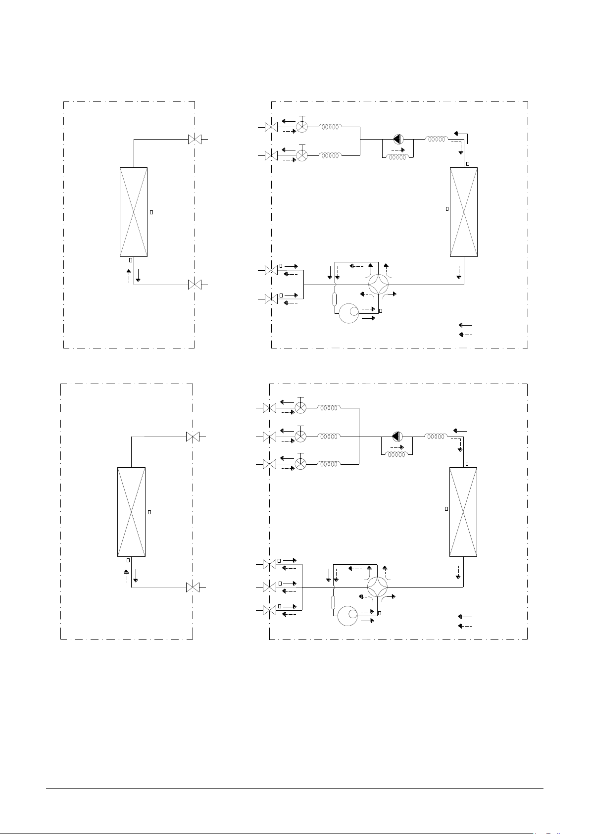
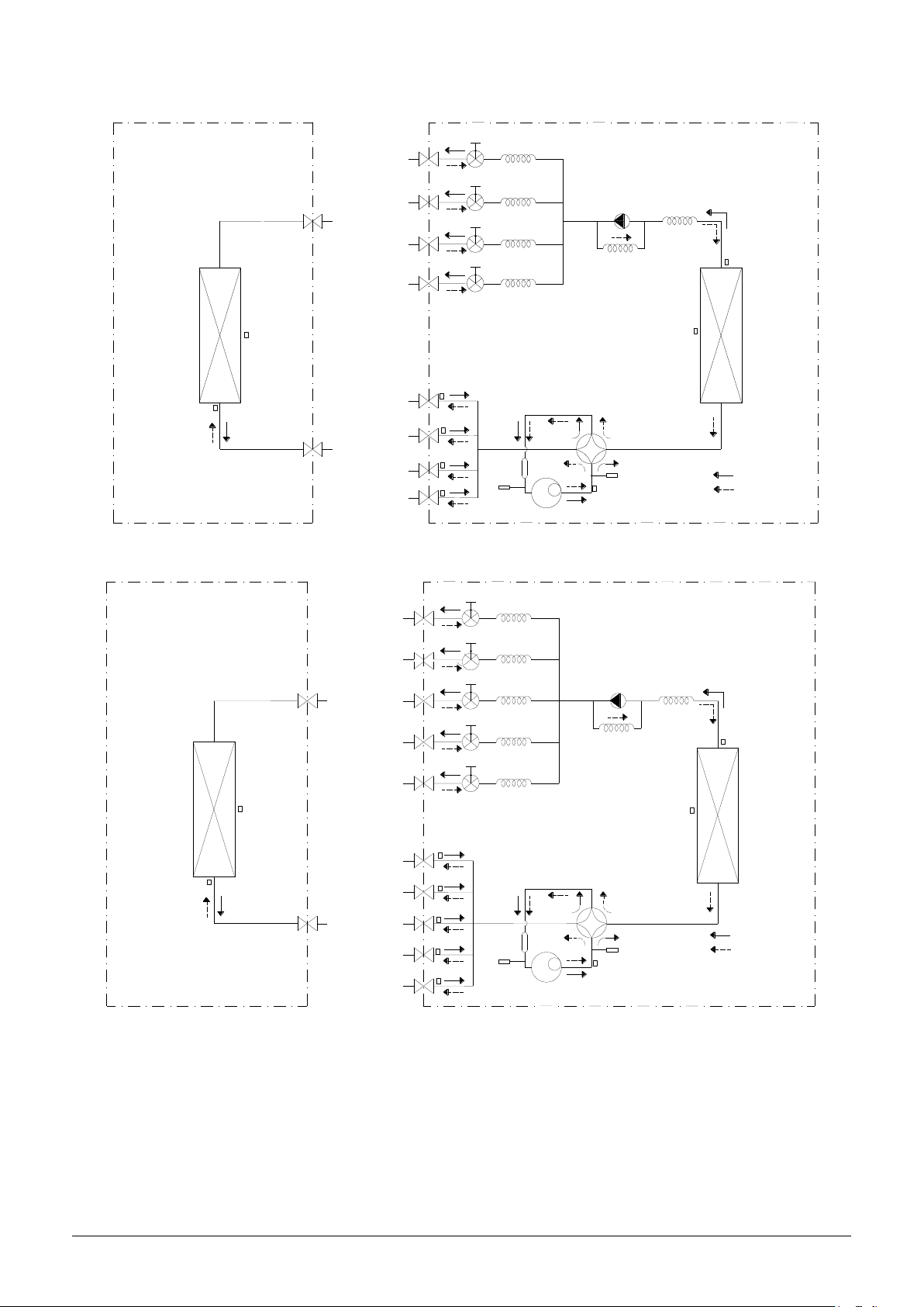
4. Refrigeration Cycle Diagram
4.1 Refrigeration circuit drawing of inverter 1 drive 2 type
INDOOR OUTDOOR
CAPILIAR
EXV
A
CAPILIAR
EXV
B
T2B-
A
Evaporator
temp. sensor outlet
Accumulator
HEAT
EXCHANGE
(EVAPORATOR)
T2
E
vaporator
temp. sensor
middle
T1 Room
temp. sensor
LIQU
ID
VALVE A
LIQU
ID
VALVE B
GAS VALVE A
GAS VALVE B
T2B-B
4.2 Refrigeration circuit drawing of inverter 1 drive 3 type
INDOOR OUTDOOR
CAPILIARY A
V
A
LIQU
ID
VALVE A
EX
Y A
Y B
Compressor
CHECK V
CAPILIARY TUBE
T5 Discharge
temp. sensor
A
4-
WA
LVE
T4 Ambient
temp. sensor
Y VALVE
T3
Condenser
temp. sensor
HEAT
EXCHANGE
(CONDENSER)
COOLING
HEATING
HEAT
EXCHANGE
(EVAPORATOR)
E
vaporator
T2
temp. sensor
middle
T1 Room
temp. sensor
VALVE B
ID
LIQU
LIQUID VALVE C
GAS VALVE A
GAS VALVE B
S
VALVE C
GA
CAPILIARY B
B
V
EX
CAPILIARY C
V
C
EX
A Evaporator
B-
T2
temp. sensor outlet
T2B-B
T2B-C
Accumulator
Compressor
K VALVE
EC
CH
CAPILIARY TUBE
T4 Ambient
temp. sensor
VALVE
Y
4-WA
T5 Discharge
temp. sensor
T3
Condenser
temp. sensor
HEAT
EXCHANGE
(CONDENSER)
COOLING
HEATING
7
4.3 Refrigeration circuit drawing of inverter 1 drive 4 type
INDOOR OUTDOOR
CA
A
LIQUID V
LIQUID V
LVE A
A
LVE B
LIQUID VALVE C
LIQUID VALVE D
EXV A
EXV B
EXV
EXV
CA
CA
C
CA
D
PIL
IARY A
PIL
IARY B
PILIARY C
PILIARY D
EC
K VALVE
CH
CAPILIARY TUBE
T3
Condense
. sensor
temp
r
HEAT
EXCHANGE
(EVAPORATOR)
Evaporator
2
T
temp. sensor
middle
T1 Room
temp. sensor
GAS VALVE A
GAS VALVE B
V
ALVE C
GAS
V
ALVE D
GAS
T2B-A Evaporator
temp. sensor outlet
T2B-B
T2B-C
T2B-D
Ac
Lo
switch
c
umulator
w pressu
4.4 Refrigeration circuit drawing of inverter 1 drive 5 type
INDOOR OUTDOOR
PILIARY A
CA
EXV
A
CA
B
C
D
E
PILIARY B
CA
PILIARY C
PILIARY D
CA
PILIARY E
CA
EXV
EXV
EXV
EXV
T2B-A Evaporator
temp. sensor outlet
HEAT
EXCHANGE
(EVAPORATOR)
T1 Room
temp. sensor
LIQ
D VALVE A
UI
LIQ
UI
D VALVE B
LIQUID VALVE C
LIQUID VALVE D
LIQUID VALVE E
GAS VALVE A
re
Compressor
T4 Ambient
temp. sensor
W
AY VALVE
4-
gh
pressure
Hi
switch
T5 Discharge
temp. sensor
CH
K VALVE
EC
CAPILIARY TUBE
T4 Ambient
temp. sensor
HEAT
EXCHANGE
(CONDENSER)
COOLING
HEATING
T3
Conden
r
se
temp. sensor
HEAT
EXCHANGE
(CONDENSER)
T2 Evaporator
temp. sensor
middle
GAS VALVE B
GA
S VALVE
GA
S VALVE
GA
VALVE E
S
T2B-B
T2B-C
C
Acc
um
Lo
w pre
switch
ulator
ssure
Com
pres
sor
T2B-D
D
T2B-E
4-
W
AY VALVE
Hig
h pre
switch
T5
arge
Disch
temp. sensor
ssure
CO
NG
OLI
HEATING
8
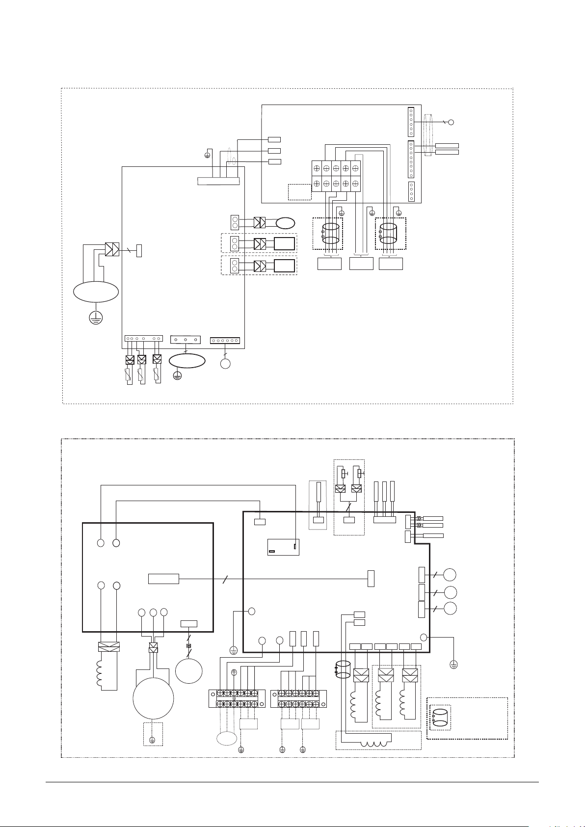
5. Wiring diagram
MUEX-14-H6.2 / MUEX-18-H6.2
BLUE
RED
BLACK
V
W
U
COMPRESSOR
Y/G
DISCHARGE TEMP. SENSOR
CN 50
3
CN 21
CONDENSER TEMP. SENSOR
AMBIENT TEMP. SENSOR
CN 7
3
DC-FAN
Y/G
CN 1A
CN 31
ELECTRONIC
EXPANSION
VALVE
CN 60
CN 17
CN 15
VALVE-B
5/6
BLACK
BLUE
BROWN
OPTIONAL
OPTIONAL
S
N
L
4-WAY
CRANKCASE
HEATER
PAN
HEATER
CN 1-3
CN 1-2
CN 1-1
NOTE:
S(1);S(2)
NO USED
CN 2
S(A)
S(2)
S(1)
S(B)
OPTIONAL
TO B
VALVE-A
CN 4
L(A)
N(A)
N
L(B)
N(B)
L
CN 3
TESTPORT
CN 7
5/6
ELECTRONIC
EXPANSIVE
VALVE
INDOOR PIPE
A
OUT TEMP
B
OPTIONAL
POWER
SUPPLY
TO A
Y/G
MUEX-21-H6.3 / MUEX-27-H6.3
RED(BROWN)
BLUE
CN4
CN2
BLUE
CN5
~
~
IPM BOARD
CN3
BLUE
BLUE
CN1
U
W
V
CN14
BLACK
RED
3
3
16022300001333
16022300000913
C
A
B
LOW PRESSURE PROTECT
RED
YELLOW
4
CN14
LOW/HIGH
MAIN BOARD
P1
P2
WHITE
WHITE
CN20
CN1
4-WAY
CN2
COM(3)
S-A
L-OUT
CN25
S-B
RY2
CN23
CN12
CompTop
S-C
CN29
ON(4)
5
P-1
N-IN
Y/G
L-IN
CN3
CN4
INDOOR PIPE
HIGH PRESSURE PROTECT
OUT TEMP
CN15
CN17
T2B
CN7
VALVE-C
VALVE-B
VALVE-A
HEAT2
CN9
CN22
CN19
CN18
P-2
CN8
CN21
CN6
HEAT1
CN5
OUTDOOR AMBIENT
TEMPERATURE SENSOR
T4
CONDENSER
T3
TEMPERATURE SENSOR
DISCHARGE SENSOR
6
6
6
Y/G
ELECTRONIC
EXPANSIVE
VALVE
ELECTRONIC
EXPANSIVE
VALVE
ELECTRONIC
EXPANSIVE
VALVE
Y/G
W(C)
DC FAN
RED
L
POWER
SUPPLY
BLACK
Y/G
N
L(A)
L(A)
BROWN
N(A)
N(A)
TO A
Y/G
S(A)
S(A)
BLUE
BLACK
BROWN
N(B)
L(B)
TO B
Y/G
BLUE
S(B)
BLACK
BROWN
L(C)
BLUE
N(C)
TO C
Y/G
BLACK
S(C)
4-WAY
HEATER1
OPTIONAL
REACT0R2 R05094A
OPTIONAL
HEATER2
NOT E:Use t he magn etic ri ng
(no t suppl ied, op tiona l part)
to hi tch the c onnec tive ca ble
of in door an d outdo or unit s
aft er inst allat ion. on e magne tic
rin g is used f or one ca ble.
REACTOR
V(S)
U(R)
COMPRESSOR
9
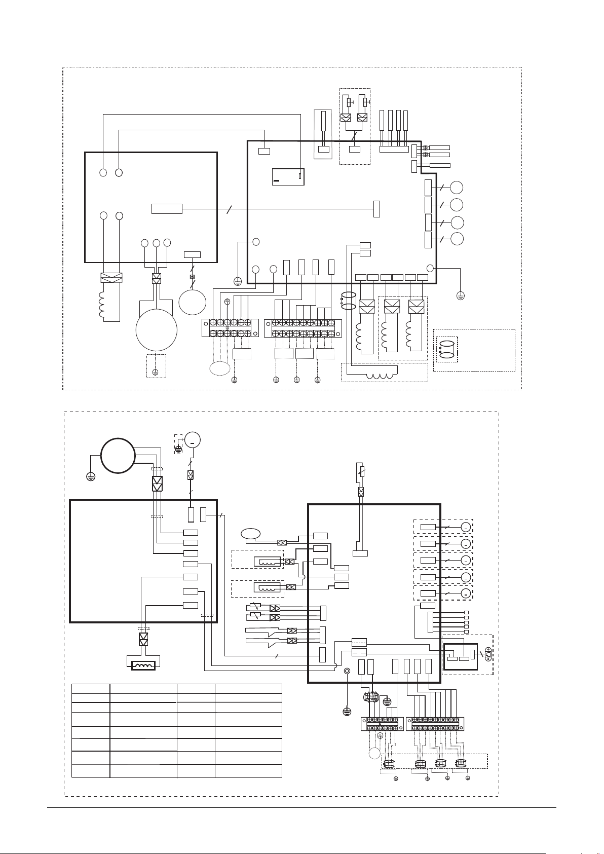
MUEX-28-H6.4
CN4
CN2
BLUE
CN5
~
~
IPM BOARD
CN3
BLUE
BLUE
16022300000803
C
A
D
RED(BROWN)
BLUE
CN29
LOW PRESSURE PROTECT
RED
4
CN14
CN12
CompTop
LOW/HIGH
L-OUT
ON(4)
CN1
U
W
V
CN14
BLACK
RED
3
5
P-1
N-IN
L-IN
Y/G
CN3
CN4
3
S-A
COM(3)
CN25
S-B
RY2
CN23
S-C
CN20
MAIN BOARD
S-D
WHITE
WHITE
CN16
CN1
B
HIGH PRESSURE PROTECT
YELLOW
CN15
T2B
VALVE-D
VALVE-C
CN21
VALVE-B
P1
P2
HEAT1
4-WAY
CN2
CN6
CN9
CN5
INDOOR PIPE
OUT TEMP
CN17
CN7
CN24
CN22
CN19
VALVE-A
CN18
P-2
HEAT2
CN8
OUTDOOR AMBIENT
TEMPERATURE SENSOR
T4
CONDENSER
T3
TEMPERATURE SENSOR
DISCHARGE SENSOR
6
6
6
6
Y/G
ELECTRONIC
EXPANSIVE
VALVE
ELECTRONIC
EXPANSIVE
VALVE
ELECTRONIC
EXPANSIVE
VALVE
ELECTRONIC
EXPANSIVE
VALVE
REACTOR
MUEX-36-H6.4
W
COMP
Y/G
DRIVER BOARD
CODE PART NAME
COMP
CAP1
EEV
FM1
FAN1
HEAT
H-PRO
U
YELLOW
COMPRESSOR
FAN MOTOR CAPACITOR
ELECTRIC EXPANSIVE
VALVE
OUTDOOR DC FAN
OUTDOOR AC FAN
CRANKCASE HEATING
HIGH PRESSURE SWITCH
V(S)
U(R)
COMPRESSOR
BLACK
RED
V
BLUE
L
Y/G
YELLOW
BLACK
RED
BLUE
BLUE
BLUE
W(C)
Y/G
DC FAN
FM1
3
CN1 9
W
V
U
CN5 4
CN5 1
CN5 3
CN5 2
L-PRO
RED
BLACK
L
N
POWER
SUPPLY
3
CN5 5
7
RED
BLACK
PFC INDUCTOR
L
LOW PRESSURE SWITCH
EXHAUST
TP
TEMPERATURE SENSOR
SV
CONDENSER
T3
TEMPERATURE SENSOR
OUTDOOR AMBIENT
T4
TEMPERATURE SENSOR
HEATSINK
TH
TEMPERATURE SENSOR
BROWN
BLUE
Y/G
S(A)
S(A)
N(A)
N(A)
L(A)
L(A)
TO A
Y/G
4-WAY1
SV
BLUE
HEAT_Y
HEAT_D
T3
T4
H-PRO
L-PRO
PART NAMECODE
4-WAY VALVE
BLACK
BLUE
OPTIONAL
OPTIONAL
BROWN
N(B)
L(B)
TO B
Y/G
7
BLUE
BLACK
S(B)
BLUE
BROWN
L(C)
BLACK
BLACK
BLUE
N(C)
TO C
Y/G
BLACK
S(C)
BROWNBROWN
L(D)
TO D
Y/G
CN3
BLUE
CN4
CN1 0
RDE
RDE
N(D)
CN8
CN9
CN7
BLUE
BLACK
S(D)
CN2 2
CN4 0
CN4 4
BLACK
Y/G
4-WAY
REACT0R2 R05094A
TP
CN3 3
MAIN BOARD
CN5
RED
CN6
CN1
CN2
P-1
RED
BLACK
L
N
POWER
SUPPLY
L(A) N(A) S(A)
TO A
HEATER1
OPTIONAL
OPTIONAL
CN3 0
BLUE
BROWN
Y/G
CN2 9
BLACK
HEATER2
5(6 )
CN2 0
A
5(6 )
CN2 1
B
5(6 )
CN1 7
C
5(6 )
CN1 8
D
5(6 )
CN1 9
E
CN1 6
T2B-A B C D E
CN13
CN5
CN2 7
CN2 8
BLUE
BROWN
L(B) N(B) S(B) L(C) N(C) S(C) L(D) N(D) S(D)
TO B
BLACK
BROWN
Y/G
TO C
BLUE
BLACK
BROWN
DR BOARD
BLUE
Y/G
NOT E:Use t he magn etic ri ng
(no t suppl ied, op tiona l part)
to hi tch the c onnec tive ca ble
of in door an d outdo or unit s
aft er inst allat ion. on e magne tic
rin g is used f or one ca ble.
M
M
M
EEV
M
M
INDOOR
PIPE OUT
TEMP A B C D E
OPTIONAL
RJ45
CN2
4
CN1
FOR USER
TO CONNECT
BLACK
OPTIONAL
TO D
Y/G
10
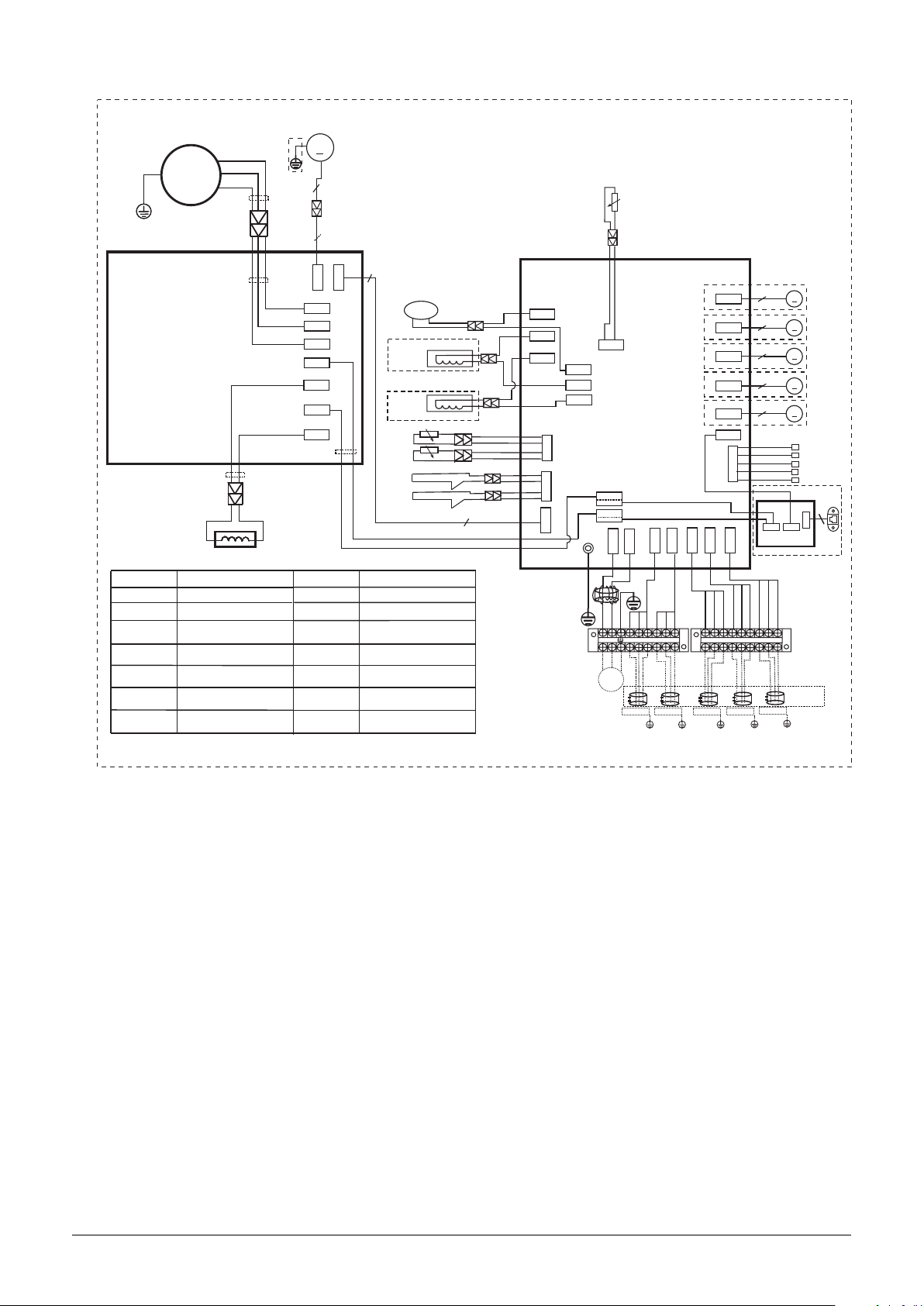
MUEX-42-H6.5
COMP
Y/G
DRIVER BOARD
YELLOW
CODE PART NAME
COMP
H-PRO
FAN MOTOR CAPACITOR
CAP1
EEV
FM1
FAN1
HEAT
HIGH PRESSURE SWITCH
ELECTRIC EXPANSIVE
VALVE
OUTDOOR DC FAN
OUTDOOR AC FAN
CRANKCASE HEATING
BLACK
W
RED
V
BLUE
U
L
COMPRESSOR
BLACK
RED
BLUE
BLUE
BLUE
YELLOW
Y/G
FM1
3
CN1 9
W
V
U
CN5 4
CN5 1
CN5 3
CN5 2
3
L
L-PRO
TP
SV
T3
T4
TH
CN5 5
7
SV
RED
BLACK
PART NAMECODE
PFC INDUCTOR
LOW PRESSURE SWITCH
EXHAUST
TEMPERATURE SENSOR
4-WAY VALVE
CONDENSER
TEMPERATURE SENSOR
OUTDOOR AMBIENT
TEMPERATURE SENSOR
HEATSINK
TEMPERATURE SENSOR
4-WAY1
BLUE
HEAT_Y
HEAT_D
T3
T4
H-PRO
L-PRO
BLUE
OPTIONAL
OPTIONAL
BLACK
BLACK
CN3
BLUE
CN4
CN1 0
RDE
RDE
CN8
CN9
CN7
BLUE
7
TP
CN3 3
CN2 2
CN4 0
CN4 4
MAIN BOARD
BLACK
CN5
RED
CN6
CN1
P-1
Y/G
RED
BLACK
L
N
POWER
CN2
L(A)
TO A
BLUE
BROWN
N(A)
S(A)
CN3 0
BLACK
BROWN
L(B)
N(B)
TO B
Y/G
CN2 8
CN2 9
BLACK
BLUE
L(C) N(C) S(C) L(D) N(D) S(D) L(E) N(E) S(E)
S(B)
TO C
Y/G
A
B
C
D
E
CN2 7
BROWN
CN2 0
CN2 1
CN1 7
CN1 8
CN1 9
CN1 6
BLUE
Y/G
5(6 )
5(6 )
5(6 )
5(6 )
5(6 )
T2B-A B C D E
CN13
CN2 6
BLACK
BLUE
BROWN
BLACK
TO D
Y/G
CN5
DR BOARD
BLACK
BLUE
BROWN
TO E
M
M
M
EEV
M
M
PIPE OUT
TEMP A B C D E
OPTIONAL
CN2
CN1
OPTIONAL
Y/G
INDOOR
RJ45
4
FOR USER
TO CONNECT
11
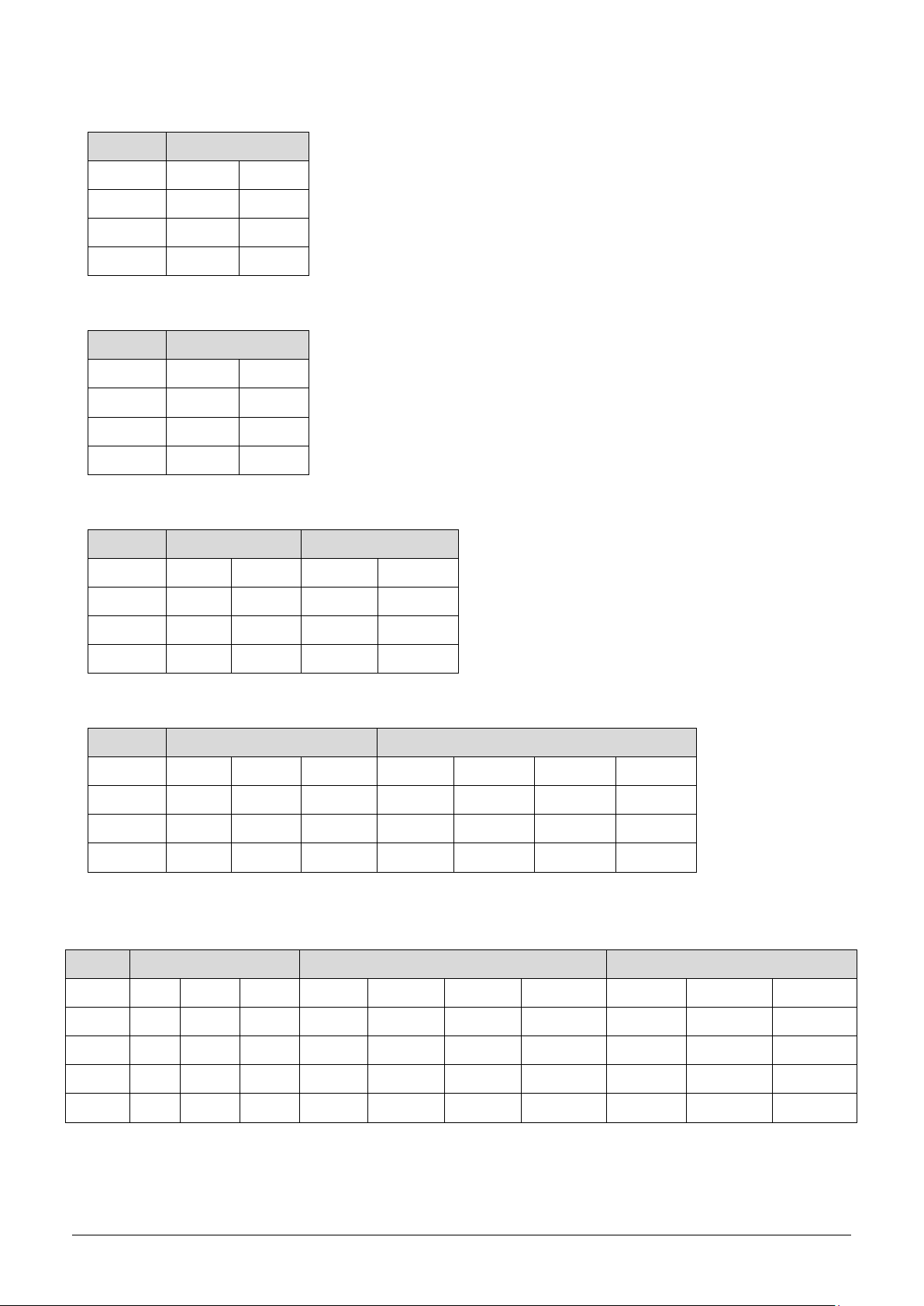
6. Indoor units combination
6.1 Indoor unit combination for MUEX-14-H6.2
One unit Two unit
7 7+7 9+9
9 7+9 9+12
12 7+12
18
6.2 Indoor unit combination for MUEX-18-H6.2
One unit Two unit
7 7+7 9+9
9 7+9 9+12
12 7+12 9+18
18 7+18 12+12
6.3 Indoor unit combination for MUEX-21-H6.3
One unit Two unit Three unit
7 7+7 9+9 7+7+7 7+9+12
9 7+9 9+12 7+7+9 9+9+9
12 7+12 9+18 7+7+12 9+9+12
18 7+18 12+12 7+9+9 7+12+12
6.4 Indoor unit combination for MUEX-27-H6.3
One unit Two unit Three unit
7 7+7 9+9 12+18 7+7+7 7+9+9 7+12+18 9+12+12
9 7+9 9+12 18+18 7+7+9 7+9+12 9+9+9 9+12+18
12 7+12 9+18 7+7+12 7+9+18 9+9+12 12+12+12
18 7+18 12+12 7+7+18 7+12+12 9+9+18
6.5 Indoor unit combination for MUEX-28-H6.4
One unit Two unit Three unit Four unit
7 7+7 9+9 12+18 7+7+7 7+9+9 7+12+18 9+12+18 7+7+7+7 7+7+9+9 7+9+9+12
9 7+9 9+12 12+24 7+7+9 7+9+12 9+9+9 12+12+12 7+7+7+9 7+7+9+12 7+9+12+12
12 7+12 9+18 18+18 7+7+12 7+9+18 9+9+12 12+12+18 7+7+7+12 7+7+9+18 9+9+9+9
18 7+18 12+12 7+7+18 7+9+24 9+9+18 7+7+7+18 7+7+12+12 9+9+9+12
24 7+24 9+24 7+7+24 7+12+12 9+12+12 7+9+9+9

One Unit
Two Unit
Three Unit
7
7+7
9+18
7+7+7
7+9+18
9+9+12
12+12+12
9
7+9
9+24
7+7+9
7+9+24
9+9+18
12+12+18
12
7+12
12+12
7+7+12
7+12+12
9+9+24
12+12+24
18
7+18
12+18
7+7+18
7+12+18
9+12+12
12+18+18
24
7+24
12+24
7+7+24
7+12+24
9+12+18
9+9
18+18
7+9+9
7+18+18
9+12+24
9+12
7+9+12
9+9+9
9+18+18
Four Unit
7+7+7+7
7+7+9+18
7+9+9+12
7+12+12+12
9+9+12+12
7+7+7+9
7+7+9+24
7+9+9+18
7+12+12+18
9+9+12+18
7+7+7+12
7+7+12+12
7+9+9+24
7+12+12+24
9+9+12+24
7+7+7+18
7+7+12+18
7+9+12+12
9+9+9+9
9+12+12+12
7+7+7+24
7+7+12+24
7+9+12+18
9+9+9+12
9+12+12+18
7+7+9+9
7+7+18+18
7+9+12+24
9+9+9+18
12+12+12+12
7+7+9+12
7+9+9+9
7+9+18+18
9+9+9+24
12+12+12+18
Five Unit
7+7+7+7+7
7+7+7+9+18
7+7+9+9+24
7+9+9+12+12
9+9+9+12+12
7+7+7+7+9
7+7+7+9+24
7+7+9+12+18
7+9+9+12+18
9+9+9+12+18
7+7+7+7+12
7+7+7+12+18
7+7+12+12+12
7+9+12+12+12
9+9+12+12+12
7+7+7+7+18
7+7+7+18+18
7+7+12+12+18
7+9+12+12+18
9+12+12+12+12
7+7+7+7+24
7+7+9+9+9
7+9+9+9+9
9+9+9+9+9
9+12+12+12+18
7+7+7+9+9
7+7+9+9+12
7+9+9+9+12
9+9+9+9+12
12+12+12+12+12
7+7+7+9+12
7+7+9+9+18
7+9+9+9+18
9+9+9+9+18
Two unit
Three unit
Four unit
7
7+7
9+18
7+7+7
7+9+18
9+9+12
12+12+12
7+7+7+7
7+7+9+24
7+9+12+12
9+9+12+12
9
7+9
9+24
7+7+9
7+9+24
9+9+18
12+12+18
7+7+7+9
7+7+12+12
7+9+12+18
9+9+12+18
12
7+12
12+12
7+7+12
7+12+12
9+9+24
12+12+24
7+7+7+12
7+7+12+18
7+9+18+18
9+12+12+12
18
7+18
12+18
7+7+18
7+12+18
9+12+12
12+18+18
7+7+7+18
7+7+18+18
7+12+12+12
9+12+12+18
24
7+24
12+24
7+7+24
7+12+24
9+12+18
7+7+7+24
7+9+9+9
7+12+12+18
12+12+12+12
9+9
18+18
7+9+9
7+18+18
9+12+24
7+7+9+9
7+9+9+12
9+9+9+9
12+12+12+18
9+12
7+9+12
9+9+9
9+18+18
7+7+9+12
7+9+9+18
9+9+9+12
7+7+9+18
7+9+9+24
9+9+9+18
12
6.6 Indoor unit combination for MUEX-36-H6.4
6.7 Indoor unit combination for MUEX-42-H6.5
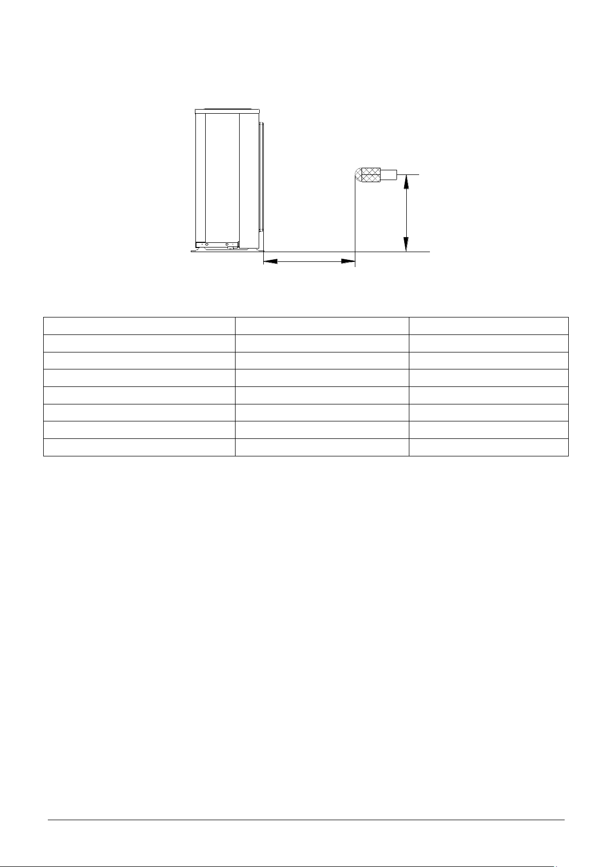
H
1.0m
Outdoor Unit
Microphone
Model
Noise Power dB(A)
Noise level dB(A)
MUEX-14-H6.2
MUEX-18-H6.2
65
56.5
MUEX-21-H6.3
65
57.5
MUEX-27-H6.3
68
59.5
MUEX-28-H6.4
66
60
MUEX-36-H6.4
68
63.5
MUEX-42-H6.5
68
62
13
7. Sound Levels
Note: H= 0.5 × height of outdoor unit
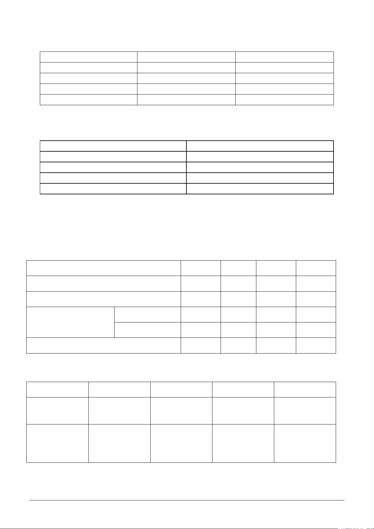
Outside diameter
Torque
Additional tightening torque
mm
N.cm
N.cm
Ф6.35
1500(153kgf.cm)
1600(163kgf.cm)
Ф9.52
2500(255kgf.cm)
2600(265kgf.cm)
Ф12.7
3500(357kgf.cm)
3600(367kgf.cm)
Rated current of appliance
Nominal cross-sectional area (mm²)
>3 and ≤6
0.75
>6 and ≤10
1
>10 and ≤16
1.5
>16 and ≤25
2.5
1 drive 2
1 drive 3
1 drive 4
1 drive 5
Max. length for all rooms (m)
30
45
60
75
Max. length for one IU (m)
20
25
30
30
Max. height difference
between IU and OU (m)
OU higher than IU
10
10
10
10
OU lower than IU
15
15
15
15
Max. height difference between IUs (m)
10
10
10
10
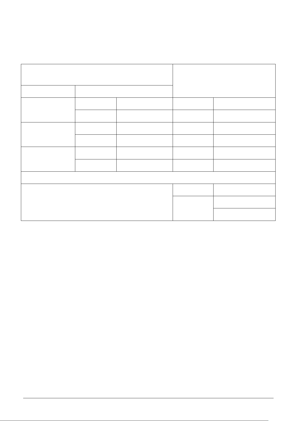
1 drive 2
1 drive 3
1 drive 4
1 drive 5
Chargeless pipe
length (m)
10
15
20
25
Additional
refrigerant charge
(g)
15 x (length for all
rooms - 10)
15 x (length for all
rooms - 15)
15 x (length for all
rooms - 20)
15 x (length for all
rooms - 25)
14
8. Installation Details
8.1 Wrench torque sheet for installation
8.2 Connecting the cables
The power cord of connect should be selected according to the following specifications sheet.
The cable size and the current of the fuse or switch are determined by the maximum current indicated on the
nameplate which located on the side panel of the unit. Please refer to the nameplate before selecting the
cable, fuse and switch.
8.3 Pipe length and the elevation
Maximum piping length and height difference
Additional refrigerant charge
Caution:
Indoor unit
Extension pipe diameter (mm/inch)
Model
Pipe diameter (mm/inch)
7K9K12K
Liquid
6.35(1/4)
Liquid
6.35(1/4)
Gas
9.52(3/8)
Gas
9.52(3/8)
18K
Liquid
6.35(1/4)
Liquid
6.35(1/4)
Gas
12.7(1/2)
Gas
12.7(1/2)
24K
Liquid
9.52(3/8)
Liquid
9.52(3/8)
Gas
15.9(5/8)
Gas
15.9(5/8)
Outdoor unit union diameter (mm/inch)
Indoor unit A/B/C/D/E
Liquid
6.35(1/4)
Gas
9.52(3/8)
12.7(1/2)
15
● Refrigerant pipe diameter is different according to indoor unit to be connected. When using the
extension pipe, refer to the tables below.
● When refrigerant pipe diameter is different from that of outdoor unit union (for 18K indoor unit), additional
transfer connector needs to be used on outdoor unit union.
8.4 Installation for the first time
Air and moisture in the refrigerant system have undesirable effects as below:
● Pressure in the system rises.
● Operating current rises.
● Cooling or heating efficiency drops.
● Moisture in the refrigerant circuit may freeze and block capillary tubing.
● Water may lead to corrosion of parts in the refrigerant system.
Therefore, the indoor units and the pipes between indoor and outdoor units must be leak tested and
evacuated to remove gas and moisture from the system.
Gas leak check (Soap water method):
Apply soap water or a liquid neutral detergent on the indoor unit connections or outdoor unit
connections by a soft brush to check for leakage of the connecting points of the piping. If bubbles come out,
the pipes have leakage.
1. Air purging with vacuum pump

(Indoor unit)
(Liquid side)
(Gas side)
Vacuum
pump
Vacuum
pump
Lo
Hi
Handle Hi
Two-way valve
Close
Manifold valve
Compound meter
Pressure
gauge
-0.1MPa
Handle Lo
Charge hose
Charge hose
(Outdoor unit)
Close
Three-way valve
16
1) Completely tighten the flare nuts of the indoor and outdoor units, confirm that both the 2-way and 3-way
valves are set to the closed position.
2) Connect the charge hose with the push pin of handle lo to the 3-way valves gas service port..
3) Connect the charge hose of handle hi connection to the vacuum pump.
4) Fully open the handle Lo of the manifold valve.
5) Operate the vacuum pump to evacuate.
6) Make evacuation for 30 minutes and check whether the compound meter indicates -0.1Mpa. If
the meter does not indicate -0.1Mpa after pumping 30 minutes, it should be pumped 20 minutes more. If the
pressure can’t achieve -0.1Mpa after pumping 50 minutes, please check if there are some leakage points.
Fully close the handle Lo valve of the manifold valve and stop the operation of the vacuum pump. Confirm
that the gauge needle does not move (approximately 5 minutes after turning off the vacuum pump).
7) Turn the flare nut of the 3-way valves about 45° counterclockwise for 6 or 7seconds after the gas
coming out, then tighten the flare nut again. Make sure the pressure display in the pressure indicator is a
little higher than the atmosphere pressure. Then remove the charge hose from the 3 way valve.
8) Fully open the 2 way valve and 3 way valve and securely tighten the cap of the 3 way valve.
17
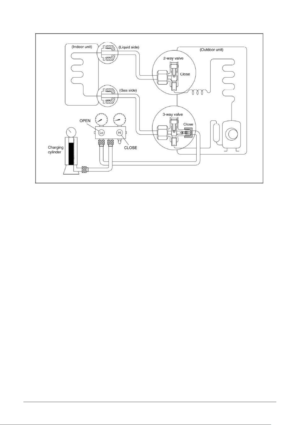
2. Air purging by refrigerant
Procedure:
1). Confirm that both the 2-way and 3-way valves are set to the closed position.
2). Connect the charge set and a charging cylinder to the service port of the 3-way valve.
3). Air purging.
Open the valves on the charging cylinder and the charge set. Purge the air by loosening the flare nut on the
2-way valve approximately 45’ for 3 seconds then closing it for 1 minute; repeat 3 times.
After purging the air, use a torque wrench to tighten the flare nut on the 2-way valve.
4). Check the gas leakage.
Check the flare connections for gas leakage.
5). Discharge the refrigerant.
Close the valve on the charging cylinder and discharge the refrigerant by loosening the flare nut on the
2-way valve approximately 45’ until the gauge indicates 0.3 to 0.5 Mpa.
6). Disconnect the charge set and the charging cylinder, and set the 2-way and 3-way valves to the open
position.
Be sure to use a hexagonal wrench to operate the valve stems.
7). Mount the valve stems nuts and the service port cap.
Be sure to use a torque wrench to tighten the service port cap to a torque 18N·m.
Be sure to check the gas leakage.
 Loading...