

mundoclima H6M, MUEX-18-H6.2, MUEX-14-H6.2, MUEX-27-H6.3, MUEX-28-H6.4 Owner's Manual
...
MULTI INVERTER SERIE H6M
Installation and owner's
manual
www.mundoclima.com
Thank you very much for purchasing our products.
Please read this manual carefully before installing
and using the unit.
CL20440 to CL20457
English

CONTENT
INSTALLATION MANUAL ............................................................................................ 3
Safety precautions ........................................................................................................ 4
Indoor unit installation ................................................................................................... 5
Outdoor unit installation ................................................................................................ 6
Refrigerant pipe connection .......................................................................................... 8
Electrical installation .....................................................................................................10
Drain joint installation ...................................................................................................12
Start up and performance testing .................................................................................12
Function of automatic wiring/piping correction .............................................................13
OWNERS MANUAL .................................................................................................... 14
Safety precautions .......................................................................................................15
Description and operating instructions .........................................................................16
Care and maintenance ................................................................................................ 20
Troubleshooting ........................................................................................................... 22
Disposal ....................................................................................................................... 24
REMOTE CONTROLLER ............................................................................................ 25
IMPORTANT
Thank you for selectiong super quality Air Conditiones. To ensure satisfactory operation for many ears to come,
this manual should be read carefully before the installation and before using the air conditioner. After reading,
store it a safe place. Please refer to the manual for questions on use or in the event that any irregularities occur.
This Air Conditioner should be used for hosehold use.
This unit must be installed by a professional according RD 795/2010, RD 1027/2007 and RD 238/2013.
WARNING
The power supply must be SINGLE-PHASE (one phase (L) and one neutral (N)) with his grounded power (GND)
and his manual switch. Any breach of these specifications involve a breach of the warranty conditions provided by
the manufacturer.
NOTE
In line with the company's policy of continual product improvement, the aesthetic and dimensional characteristics,
technical data and accessories of this appliance may be changed without notice.
ATTENTION
Read this manual carefully before installind or operating you new air conditioning unit. Make sure to save this
manual for future reference.
2

INSTALLATION MANUAL
Before using your air conditioner, please read
this manual carefully and keep it for future reference..
INVERTER SPLIT-TYPE
ROOM AIR CONDITIONER
The design and specifications are subject to
change without prior notice for
product improvement. Consult with the sales
agency or manufacturer for details.
Read This Manual:
Inside you will find many helpful hints on how to use and
maintain your air conditioner properly.
Just a little preventative care on your part can save you
a great deal of time and money over the life of your air
conditioner.
You'll find manyanswers to common problems in the
chart of troubleshooting tips. If you review the chart of
Troubleshooting Tips first, you may not need to call for
service.
3

SAFETY PRECAUTIONS
1. Safety precautions
Read the follow SAFETY PRECAUTIONS carefully before installation.
Electrical work must be installed by a l ic en se d el ectrician. Be sure to use the correct rating
of the power plug and main circu it f or t he m od el t o be i ns ta lled.
Incorrect installation due to igno ri ng o f th e in st ru ction will cause harm or damage.
The seriousness is classified by the following indications.
WARNING
CAUTION
This symbol indicates the possibility of death or serious injury.
This symbol indicates the possibility of injury or damage to property.
The items to be followed are classified by the symbols:
Symbol with background white denotes item that is PROHIBITED from doing.
WARNING
1) Engage dealer or specialist for installation. If installation done by the user is defective, it will cause water
leakage, electrical shock fire.
2) Install according to this installation instructions strictly. If installation is defective, it will cause water
leakage, electrical shock fire.
3) Use the attached accessories parts and specified parts for installation. otherwise, it will cause the set to fall,
water leakage, electrical shock fire.
4) Install at a strong and firm location which is able to withstand the set s weight. If the strength is not enough
or installation is not properly done, the set will drop and cause injury.
5) For electrical work, follow the local national wiring standard, regulation and this installation instructions. An
independent circuit and single outlet must be used. If electrical circuit capacity is not enough or defect found
in electrical work, it will cause electrical shock fire.
6) Use the specified cable and connect tightly and clamp the cable so that no external force will be acted on
the terminal. If connection or fixing is not perfect, it will cause heat-up or fire at the connection.
7) Wiring routing must be properly arranged so that control board cover is fixed properly. If control board cover
is not fixed perfectly, it will cause heat-up at connection point of terminal, fire or electrical shock.
8) When carrying out piping connection, take care not to let air substances other than the specified
refrigerant go into refrigeration cycle. Otherwise, it will cause lower capacity, abnormal high pressure
in the refrigeration cycle, explosion and injury.
9) Do not modify the length of the power supply cord or use of extension cord, and do not share the
single outlet with other electrical appliances. Otherwise, it will cause fire or electrical shock.
,
CAUTION
1) This equipment must be earthed and installed with earth leakage current breaker. It may cause electrical
shock if grounding is not perfect.
2) Do not install the unit at place where leakage of flammable gas may occur. In case gas leaks and
accumulates at surrounding of the unit, it may cause fire.
3) Carry out drainage piping as mentioned in installation instructions. If drainage is not perfect, water
may enter the room and damage the furniture.
4
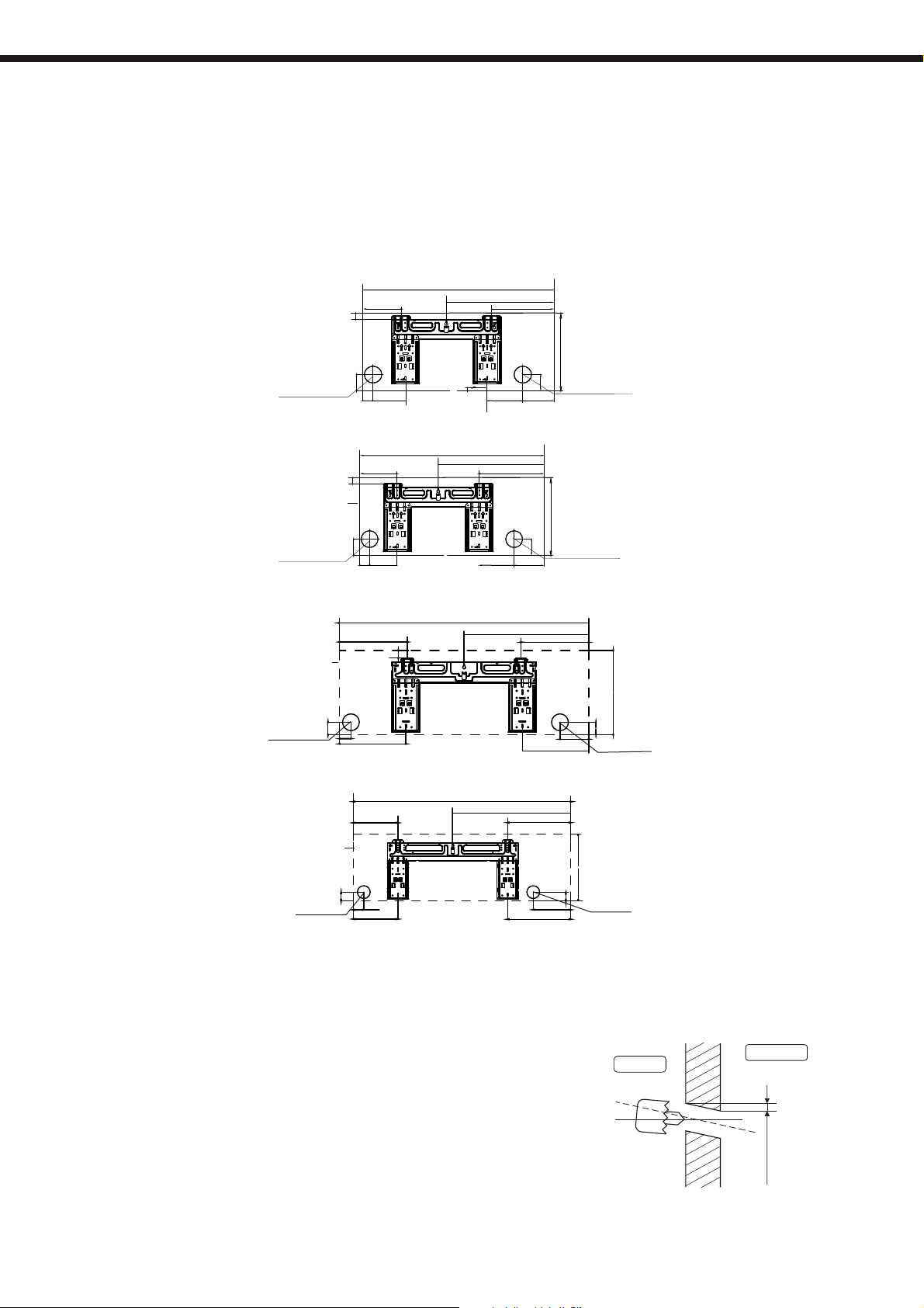
INDOOR UNIT INSTALLATION
2. Indoor unit installation
Fit the installation plate
1)
Fit the installation plate horizontally on structural parts of the wall with spaces
arround the installation plate.
2)
If the wall is made of brick, concrete or like, drill five or eight 5mm diameter holes
in the wall. Insert Clip anchor for appropiates mounting screws.
Dimensiones
unidad interior
Agujero lado
izquierdo 65 mm
Dimensiones
unidad interior
Agujero lado
izquierdo 65 mm
Dimensiones
unidad interior
Agujero lado
izquierdo 65 mm
128 mm
27 mm
63 mm
107 mm 137 mm
39 mm
MUPR-09-H6M
163 mm
27 mm
53 mm
128 mm 112 mm
48 mm
39 mm
262.2 mm
29.2 mm
44 mm
256.6 mm
MUPR-12-H6M
717 mm
805 mm
964 mm
412 mm
11mm(0.43in)
427.9 mm
MUPR-18-H6M
237 mm
224.6 mm
113 mm
481.6 mm
117 mm
53 mm
262 mm
256.6 mm
302 mm
Agujero lado derecho
63 mm
65 mm
302 mm
Agujero lado
derecho
65 mm
48 mm
111 mm
Agujero lado
derecho 65mm
325 mm
Dimensiones
unidad interior
Agujero lado
izquierdo 65 mm
45 mm
227.8 mm
53.7 mm
227.8 mm
1106 mm
MUPR-24-H6M
598.4 mm
Drill a hole in the w all
1. Determine hole positions according to left and right
side of the installation plate. The hole center is obtained
by measuring the distance as shown in the diagram above.
2. Dirll the piping plate hole with φ65mm hole-core drill.
3. Drill the piping hole at either the right or the left and the
hole should be slightly slanted to the outdoor side.
4. Always take steps to protect the pipe when drilling metal
grid, metal plate or the like.
5
319.5 mm
189.4 mm
319.5 mm
45 mm
342 mm
Agujero
lado derecho 65 mm
Wall
Outdoor
Indoor
5-7mm
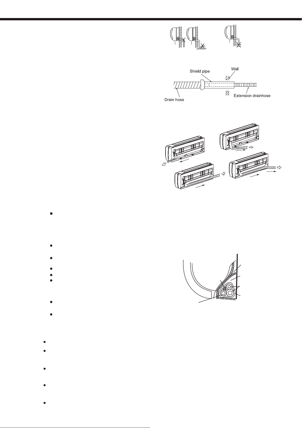
INDOOR AND OUTDOOR UNIT INSTALLATION
Connective pipe and drainage installation
1. Run the drain hose sloping downward.
Do not install the drain hose as
illustrated in Fig.7.
2. When connecting extension drain hose,
insulate the connecting part of extension
drain hose with a shield pipe, do not let
the drain hose slack.
Connective pipe installation
1. For the left-hand and right-hand piping,
remove the pipe cover from the side
panel.
2. For the rear-right-hand and rear-left-hand
piping, install the piping as shown in Fig.10.
3. Fix the end of the connective pipe. (Refer
to Tightening Connection in REFRIGERANT
PIPING CONNECTION)
Piping and w rapping
Bundle the tubing, connecting cable, and drain
hose with tape securely, evenly as shown in
Fig.11.
Because the condensed water from rear of the
indoor unit is gathered in ponding box and is
piped out of room. Do not put anything else in
the box.
Do not block water flow by a rise.
Right-hand piping
Left-hand piping
Fig.9
Do not put the end of
drain hose into water.
Fig.8
Rear-right piping
Rear-left piping
Fig.10
Caution
Connect the indoor uni t fi rs t, t he n th e
outdoor unit.
Do not allow the piping to let out fro m
the back of the indoor unit.
Be careful not to let the drain hose sla ck .
Heat insulated both of the aux il ia ry p ip ing.
Be sure that the drain hose is loc at ed a t
the lowest side of the bundl e. L oc at in g
at the upper side can cause drain pa n
to overflow inside the unit.
Never intercross nor i nt er tw is t th e po we r
wire with any other wiring .
Run the drain hose sloped do wn wa rd t o
drain out the condensed wa te r sm oo th ly.
3. Outdoor unit installation
Install the outdoor unit on a rigid base to
Determine the air outlet direction where the
the installation place is exposed to strong wind
properly by putting the unit lengthwise along the
Specially in windy area, install the unit to prevent
installation, the installation bracket should
installation bracket diagram.
The installation wall should be solid brick,
actions to reinforce, damping supporting should
wall, bracket and the air conditioner should be
Be sure there is no obstacle which block
prevent increasing noise level and vibration.
Indoor unit
Connective
cable
.
.
.
.
.
.
.
.
.
.
. .
.
.
.
.
.
.
.
.
.
.
.
.
.
.
.
.
.
.
.
.
Ponding box
Pipe room
Connective
pipe
Wrapping belt
Drain hose
Fig.11
discharged air is not blocked. In the case that
such as a seaside, make sure the fan operating
wall or using a dust or shield plates.
the admission of wind. If need suspending
accord with technique requirement in the
concrete or the same intensity construction, or
be taken. The connection between bracket and
firm, stable and reliable.
radiating air.
6
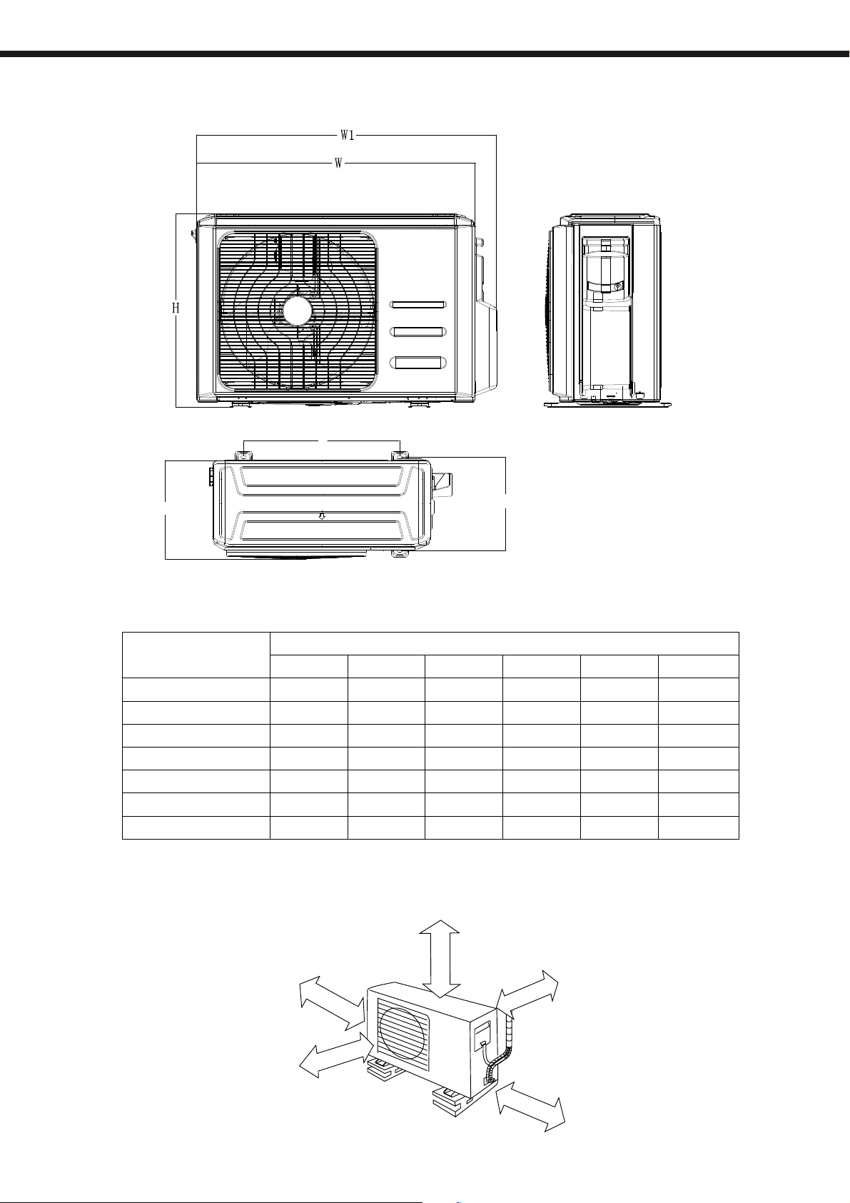
Dimensions
OUTDOOR UNIT INSTALLATION
A
D
Model
W D H W1 A B
MUEX-14-H6.2 800 333 554 860 514 340
MUEX-18-H6.2 800 333 554 860 514 340
MUEX-21-H6.3 845 363 702 923 540 350
MUEX-27-H6.3 845 363 702 923 540 350
MUEX-28-H6.4 946 410 810 1034 673 403
MUEX-36-H6.4 946 410 810 1034 673 403
MUEX-42-H6.5 946 410 810 1034 673 403
B
Space for installation and maintenance
Unit: mm
> 60 cm
> 30 cm
> 30 cm
> 200 cm
> 60 cm
7
REFRIGERANT PIPE CONNECTION
30
45
60
75
25
30
35
35
15
15
15
15
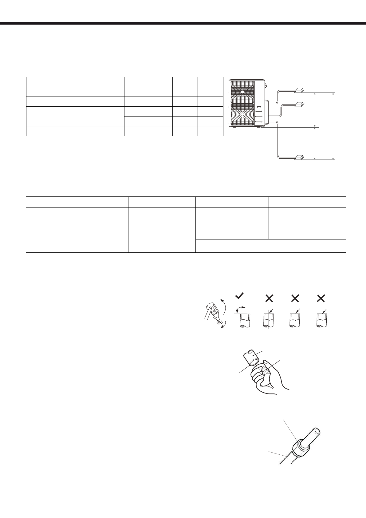
4. Refrigerant pipe connection
Before installing, make sure that the height difference, the length of refrigerant pipe and number of bends
between indoor and outdoor units, meet the following specifications.
UNIT
Max. Length for al l roo ms (m)
Max. Length for on e ind oor u nit (m)
Max. height diff ere nt be twe en
indoor and outdoor un it (m)
Max. height diff ere nt be twe en in doo r uni ts (m)
OU higher than IU
OU lower than IU
Additional charge (R410A)
2 x 1 (H6.2)
3 x 1 (H6.3)
15 15 15 15
10 10 10 10
4 x 1 (H6.4)
5 x 1 (H6.5)
Outdoor unit
Indoor unit
Indoor unit
Indoor unit
Max. height difference
15m
10m
15m
UNIT
Charged until
Additional
charge
(g)
2 x 1 (H6.2)
15m
(Total Liquid Length 1/4")
Total Liquid Length 1/4":
15 x (Total length - 15)
(Total Liquid Length 1/4")
3 x 1 (H6.3)
22,5m
Total Liquid Length 1/4":
15 x (Total length - 22,5)
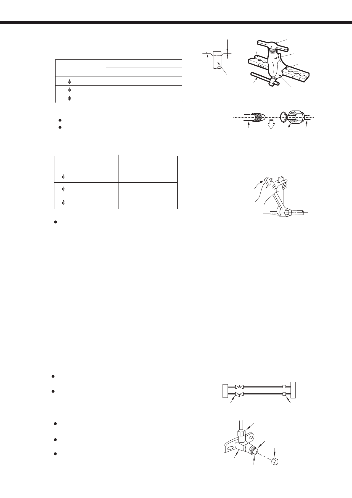
1. Flaring work
Main cause for refrigerant leakage
is due to defect in the flaring work.
Carry out correct flaring work
using the following procedure:
A: Cut the pipes and the cable.
1. Use the piping kit accessory or pipes
purchased locally.
2. Measure the distance between the indoor
and the outdoor unit.
3. Cut the pipes a little longer than the
measured distance.
4. Cut the cable 1.5m longer than the pipe
length.
4 x 1 (H6.4)
30m (Total Liquid Length 1/4")
7,5m (Total Liquid Length 3/8")
Total Liquid Length 1/4":
15 x (Total length - 30) 15 x (Total length - 37,5)
Total Liquid Length 3/8":
30 x (total length - 7,5)
。
90
Point down
37,5m (Total Liquid Length 1/4")
7,5m (Total Liquid Length 3/8")
Total Liquid Length 1/4":
Oblique
Fig.5 4
Pipe
Reamer
Fig.5 5
5 x 1 (H6.5)
Roughness
Burr
B: Burr removal
Flare nut
1. Completely remove all bur rs f ro m th e cu t
cross section of pipe/tube.
2. Put the end of the copper tube/pipe i n a
downward direction as you re mo ve b ur rs i n
order to avoid dropping bu rr s in to t he t ub in g.
Copper tube
C: Putting nut on
Remove flare nuts attached to indoor a nd
Fig.5 6
outdoor unit, then put them on pipe/tube
having completed burr remo va l. (n ot p os si ble
to put them on after flaring work)
8
REFRIGERANT PIPE CONNECTION
D: Flaring work
Firmly hold copper pip e in a d ie i n th e
dimension shown in the table b el ow.
Outer diam.
(mm)
A(mm)
Max.
6.35 1.3
9.53
12.7
12.7
1.6 1.0
1.8
1.8
Tightening connection
Align the center of the pipes.
Sufficiently tighten the flare
nut with fingers, and then tighten
it with a spanner and torque wrench
as shown in Fig.58 & 59
Outer
diam.
6.35
9.52
12.7
Tightening
torque(N.cm)
1500
(153kgf.cm)
2500
(255kgf.cm)
3500
(357kgf.cm)
Additional tightening
torque(N.cm)
1600
(163kgf.cm)
2600
(265kgf.cm)
3600
(367kgf.cm)
Caution
Excessive torque can break nut
depending on installation conditions.
Min.
0.7
1.0
1.0
Bar
"A"
Copper pipe
Clamp handle
Indoor unit tubing Flare nut Pipings
Handle
Bar
Yoke
Cone
Red arrow mark
Fig.5 7
Fig.5 8
Fig.5 9
Air purging
Air and moisture in the refrig er an t sy st em h av e undesirable effects as indicated below:
● Pressure in the system rises.
● Operating current rises.
● Cooling or heating efficiency drops.
● Moisture in the refrigerant circ ui t ma y fr ee ze a nd b lock capillary tubing.
● Water may lead to corrosion of parts in the refrigeration system.
Therefore, the indoor unit and tub in g be tw ee n th e in door and outdoor unit must be leak tested
and evacuated to remove an y no nc on de nsables and moisture from the system.
Air purging w ith vacuum pump
●
Preparation
Check that each tube(both liqu id a nd g as s id e tu be s) between the indoor and outdoor units
have been properly con ne ct ed a nd a ll w iring for the test run has been completed. Remove
the service valve caps fro m bo th t he g as a nd t he l iq uid side on the outdoor unit. Note that
both the liquid and the gas side ser vi ce v al ve s on the outdoor unit are kept closed at this
stage.
●
Pipe length and refriger an t am ou nt :
When relocate the unit to another place,
perform evacuation using vacuum pump.
Make sure the refrigerant added into the air
conditioner is liquid form in any case.
Outdoor
unit
Packed valve
Refrigerant
A
B
Gas side
Liquid side
Half union
Indoor
unit
C
D
Fig.6 5
Caution in handling the pack ed valve
Open the valve stem until it hits against the
stopper. Do not try to open it further.
Securely tighten the valve stem cap with a
spanner or the like.
Valve stem cap tightening torque (See
Tightening torque table in previous page ).
Valve body
Flare nut
Stopper
Valve stem
Cap
Fig.6 6
9
ELECTRICAL INSTALLATION
5. Electrical installation
Safety standards
- The supply voltage must be within a range of 90% to 110% of nominal value.
- The thermal circuit breaker and breaker should be 1.5 times the nominal consumption.
- All installation and wiring must comply with local and national average and the installation should
be performed by qualified personnel.
- The minimum section of wiring should be as follows according to consumption.
Connect the cable to the outdoor unit
1. Remove the electrical control board cover
from the outdoor unit by loosening the screw
as shown in figure.
2. Connect the connective cables to the
terminals as identified with their respective
matched numbers on the terminal block of
indoor and outdoor units.
3. Secure the cable onto the control board with
the cord clamp.
4. To prevent the ingress of water, from a loop
of the connective cable as illustrated in the
installation diagram of indoor and outdoor
units.
5. Insulate unused cords (conductors) with
PVC-tape.Process them so they do not
touch any electrical or metal parts.
Screw
Cover
Model ICP
MUEX-14-H6.2
MUEX-18-H6.2
MUEX-21-H6.3
MUEX-27-H6.3
MUEX-28-H6.4
MUEX-36-H6.4
MUEX-42-H6.5
Pow er W ire
2 x 2,5 + T mm
2 x 2,5 + T mm
2 x 4 + T mm
2 x 4 + T mm
2 x 4 + T mm
2 x 6 + T mm
2 x 6 + T mm
2
2
2
2
2
2
2
Indoor unit connection
a) Wall mounted MUPR-H6M
W
Empty
Note:
The wall mounted indoor unit has terminal , that can not be connected.
2(N)
1(L)
L N S T
S
b) Duct MUCR-H6M
L(L1)
N(2)
L N S T
W
Differential sw itch
16 A 2P 30mA
16 A 2P 30mA
20 A 2P 30mA
20 A 2P 30mA
20 A 2P 30mA
25 A 2P 30mA
25 A 2P 30mA
c) Cassette MUCSR-H6M
L
S
N
L N S T
S
10
2 x 1
MUEX-14-H6.2
MUEX-18-H6.2
ELECTRICAL INSTALLATION
L(A)
N
L
N(A)
S(A)
L(B)
N(B)
S(B)
3 x 1
MUEX-21-H6.3
MUEX-27-H6.3
POWER
N
L
POWER
W 1(L) 2(N) S W 1(L) 2(N) S
TO A TO B
L(A)
N(A)
S(A)
W 1(L) 2(N) S
TO A
L(C)
S(B)
L(B)
W 1(L) 2(N) S
N(B)
N(C)
W 1(L) 2(N) S
TO B TO C
S(C)
4 x 1
5 x 1
MUEX-28-H6.4
MUEX-36-H6.4
MUEX-42-H6.5
N
L
POWER
N
L
POWER
L(A)
W 1(L) 2(N) S
TO A
L(A)
N(A)
N(A)
S(A)
S(A)
L(B)
N(B)
S(B)
L(B)
W 1(L) 2(N) S
TO B
N(B)
S(B)
L(C)
L(C)
N(C)
N(C)
W 1(L) 2(N) S
TO C
S(C)
S(C)
L(D)
L(D)
N(D)
N(D)
S(D)
S(D)
W 1(L) 2(N) S
TO D
L(E)
N(E)
S(E)
W 1(L) 2(N) S
TO A
W 1(L) 2(N) S
TO B
11
W 1(L) 2(N) S
TO C
W 1(L) 2(N) S
TO D
W 1(L) 2(N) S
TO E

DRAIN JOINT and
START UP AND PERFORMANCE TESTING
6 . Drain joint installation
Fit the seal into the drain joint, then insert the
drain joint into the base pan hole of outdoor unit,
rotate 90 to securely assemble them.
。
Connecting the drain joint with an extension drain
hose (Locally purchased), in case of the water
draining off the outdoor unit during the heating
mode.
NOTE: The drain joint differ from appl ia nc e
to appliance.
7. Start up and performance testing
Prior check s
Seal
(1)
Drain joint
(2)
Base pan hole of
outdoor unit
Seal
Drain pipe
-
Measure the voltage supply and make sure it is within the specified range.
-
Testing must be performed in all modes of operation.
-
To operate in cool mode, press the ON/OFF button of the remote controller to place the unit in
cooling mode and select a temperature below room temperature.
-
To operate in heat mode, press the ON/OFF button of the remote controller to place the unit in
heating mode and select a temperature above room temperature.
-
You can also check the manual button. This is used when you do not have the remote controller and
and is located under the front panel.
12
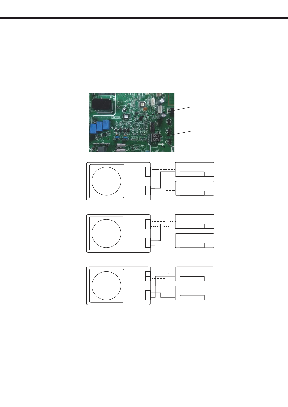
AUTOMATIC WIRING/PIPING CORRECTION
8. Function of automatic wiring/piping correction
Automatic Wiring/Piping Correction Function:
More recent models now feature automatic correction of wiring/piping errors. Press the "check
switch" on the outdoor unit PCB board for 5 seconds until the LED displays "CE”, indicating that this
function is working, Approximately 5-10 minutes after the switch is pressed, the "CE" disappears,
meaning that the wiring/piping error is corrected and all wiring/piping is properly connected.
Check switch
LED display
Correct wiring
Terminal
block
Liquid/
Gas pipe
Outdoor unit
Incorrect wiring
B
A
Indoor unit B
B
A
Indoor unit A
Terminal
block
Liquid/
Gas pipe
Outdoor unit
Incorrect wiring
Terminal
block
Liquid/
Gas pipe
Outdoor unit
B
A
Indoor unit B
B
A
Indoor unit A
B
A
Indoor unit B
B
A
Indoor unit A
How To Activate This Function:
1. Check that outside temperature is above 5℃.
(This function does not work when outside temperature is not above 5℃)
2. Check that the stop valves of the liquid pipe and gas pipe are open.
3. Turn on the breaker and wait at least 2 minutes.
4. Press the check switch on the outdoor PCB board unit LED display "CE".
13

OWNER´S MANUAL
Before using your air conditioner, please read
this manual carefully and keep it for future reference..
INVERTER SPLIT-TYPE
ROOM AIR CONDITIONER
The design and specifications are subject to
change without prior notice for
product improvement. Consult with the sales
agency or manufacturer for details.
Read This Manual:
Inside you will find many helpful hints on how to use and
maintain your air conditioner properly.
Just a little preventative care on your part can save you
a great deal of time and money over the life of your air
conditioner.
You'll find manyanswers to common problems in the
chart of troubleshooting tips. If you review the chart of
Troubleshooting Tips first, you may not need to call for
service.
14
SAFETY PRECAUTIONS
1. Safety precautions
Read the follow SAFETY PRECAUTIONS carefully before installation.
Electrical work must be installed by a l ic en se d el ectrician. Be sure to use the correct rating
of the power plug and main circu it f or t he m od el t o be i ns ta lled.
Incorrect installation due to igno ri ng o f th e in st ru ction will cause harm or damage.
The seriousness is classified by the following indications.
WARNING
CAUTION
This symbol indicates the possibility of death or serious injury.
This symbol indicates the possibility of injury or damage to property.
The items to be followed are classified by the symbols:
Symbol with background white denotes item that is PROHIBITED from doing.
WARNING
1) Engage dealer or specialist for installation. If installation done by the user is defective, it will cause water
leakage, electrical shock fire.
2) Install according to this installation instructions strictly. If installation is defective, it will cause water
leakage, electrical shock fire.
3) Use the attached accessories parts and specified parts for installation. otherwise, it will cause the set to fall,
water leakage, electrical shock fire.
4) Install at a strong and firm location which is able to withstand the set s weight. If the strength is not enough
or installation is not properly done, the set will drop and cause injury.
5) For electrical work, follow the local national wiring standard, regulation and this installation instructions. An
independent circuit and single outlet must be used. If electrical circuit capacity is not enough or defect found
in electrical work, it will cause electrical shock fire.
6) Use the specified cable and connect tightly and clamp the cable so that no external force will be acted on
the terminal. If connection or fixing is not perfect, it will cause heat-up or fire at the connection.
7) Wiring routing must be properly arranged so that control board cover is fixed properly. If control board cover
is not fixed perfectly, it will cause heat-up at connection point of terminal, fire or electrical shock.
8) When carrying out piping connection, take care not to let air substances other than the specified
refrigerant go into refrigeration cycle. Otherwise, it will cause lower capacity, abnormal high pressure
in the refrigeration cycle, explosion and injury.
9) Do not modify the length of the power supply cord or use of extension cord, and do not share the
single outlet with other electrical appliances. Otherwise, it will cause fire or electrical shock.
,
CAUTION
1) This equipment must be earthed and installed with earth leakage current breaker. It may cause electrical
shock if grounding is not perfect.
2) Do not install the unit at place where leakage of flammable gas may occur. In case gas leaks and
accumulates at surrounding of the unit, it may cause fire.
3) Carry out drainage piping as mentioned in installation instructions. If drainage is not perfect, water
may enter the room and damage the furniture.
15
 Loading...