

mundoclima CL23400, CL23407 Installation Manual
MVD
Ceiling Floor MVD DC
Installation manual
www.mundoclima.com
CL23400 to CL23407
English
Installation manual Ceiling Floor
CONTENTS PAGE
PRECAUTIONS.......................................................................................1
INSTALLATION INFORMATION................................................................2
ATTACHED FITTINGS.............................................................................2
INDOOR UNIT INSTALLATION.................................................................3
INSTALL THE CONNECTING PIPE..........................................................5
CONNECT THE DRAIN PIPE...................................................................6
WIRING.................................................................................................7
CONTROL OPERATION............................................................................8
TEST OPERATION................................................................................11
1. PRECAUTIONS
Be sure to be in conformity with the local, national and
international laws and regulations.
Read "PRECAUTIONS" carefully before installation.
The following precautions include important safty items.
Observe them and never forget.
Keep this manual with the owner's manual in a handy place
for future reference.
The safty precautions listed here are divided into two categories. In
either case, important safty information is listed which must be read
.
carefully
WARNING
Failure to observe a warning may result in death.
CAUTION
Failure to observe a caution may result in injury or
damage to the equipment.
After completing the installation, make sure that the unit operates
properly during the start-up operation. Please instruct the customer
on
to
how
customers that they should store this installation manual along with
the owner's manual for future reference.
operate the unit and keep it maintained.Also, inform
ARNING
W
Be sure only trained and qualified service personnel to
install, repair or service the equipment.
Improper installation, repair, and maintenance may result in
electric shocks, short-circuit, leaks, fire or other damage to
the equipment.
Install according to this installation instructions strictly.
If installation is defective, it will cause water leakage,
electrical shock and fire.
When installing the unit in a small room, take measures
against to keep refrigerant concentration from exceeding
allowable safety limits in the event of refrigerant leakage.
Contact the place of purchase for more information.
Excessive refrigerant in a closed ambient can lead to oxygen
deficiency.
Use the attached accessories parts and specified parts
for installation.
otherwise,
electrical shock and fire.
Install at a strong and firm location which is able to
withstand the set' s weight.
If the strength is not enough or installation is not properly
done, the set will drop to cause injury.
The appliance shall not be installed in the laundry.
Before obtaining access to terminals, all supply circuits
must be disconnected.
The appliance must be positioned so that the plug is
accessible.
The enclosure of the appliance shall be marked by word,
or by symbols, with the direction of the fluid flow.
For electrical work, follow the local national wiring
standard, regulation and this installation instructions. An
independent circuit and single outlet must be used.
If electrical circuit capacity is not enough or defect in
electrical work, it will cause electrical shock fire.
Use the specified cable and connect tightly and clamp
the cable so that no external force will be acted on the
terminal.
If connection or fixing is not perfect, it will cause heat-up or
fire at the connection.
Wiring routing must be properly arranged so that control
board cover is fixed properly.
If control board cover is not fixed perfectly, it will cause
heat-up at connection point of terminal, fire or electrical
shock.
If the supply cord is damaged, it must be replaced by the
manufacture or its service agent or a similarly qualified
person in order to avoid a hazard.
An all-pole disconnection switch having a contact
separation of at least 3mm in all poles should be
connected in fixed wiring.
When carrying out piping connection, take care not to let
air substances go into refrigeration cycle.
Otherwise, it will cause lower capacity, abnormal high
pressure in the refrigeration cycle, explosion and injury.
Do not modify the length of the power supply cord or use
of extension cord, and do not share the single outlet with
other electrical appliances.
Otherwise, it will cause fire or electrical shock.
Carry out the specified installation work after taking into
account strong winds, typhoons or earthquakes.
Improper installation work may result in the equipment falling
and causing accidents.
it will cause the set to fall, water leakage,
1
Installation manual
Ceiling Floor
If the refrigerant leaks during installation, ventilate the
area immediately
T
oxic gas may be produced if the refrigerant comes into the
place contacting with fire.
The temperature of refrigerant circuit will be high, please
keep the interconnection cable away from the copper
tube.
completing
After
refrigerant does not leak.
Toxic gas may be produced if the refrigerant leaks into the
room and comes into contact with a source of fire, such as a
fan heater, stove or cooker.
.
the installation work, check that the
CAUTION
Ground the air conditioner
Do not connect the ground wire to gas or water pipes,
lightning rod or a telephone ground wire.Incomplete
grounding may result in electric shocks.
Be sure to install an earth leakage breaker.
Failure to install an earth leakage breaker may result in
electric shocks.
Connect the outdoor unit wires , then connect the indoor
unit wires.
ou are not allow to connect the air conditioner with the
Y
power source until wiring and piping the air conditioner is
done.
While following the instructions in this installation
manual, install drain piping in order to ensure proper
drainage and insulate piping in order to prevent
condensation.
Improper drain piping may result in water leakage and
property damage.
Install the indoor and outdoor units, power supply wiring
and connecting wires at least 1 meter away from
televisions or radios in order to prevent image
interference or noise.
Depending on the radio waves, a distance of 1 meter may not
be sufficient enough to eliminate the noise.
The appliance is not intended for use by young children
or inferm persons without supervision.
Don't install the air conditioner in the following locations:
There is petrolatum existing.
There is salty air surrounding (near the coast).
There is caustic gas (the sulfide, for example) existing
in the air (near a hot spring).
The Volt vibrates violently (in the factories).
In buses or cabinets.
In kitchen where it is full of oil gas.
There is strong electromagnetic wave existing.
There are inflammable materials or gas.
There is acid or alkaline liquid evaporating.
Other special conditions.
The appliance shall not be installed in the laundry.
.
2. INST
T
first.
The air conditioner must be installed by qualified persons.
When installing the indoor unit or its tubing, please follow
this manual as strictly as possible.
If the air conditioner is installed on a metal part of the
building, it must be electrically insulated according to the
relevant standards to electrical appliances.
When all the installation work is finished, please turn on
the power only after a thorough check.
Regret for no further announcement if there is any change
of this manual caused by product improvement.
INST
3. A
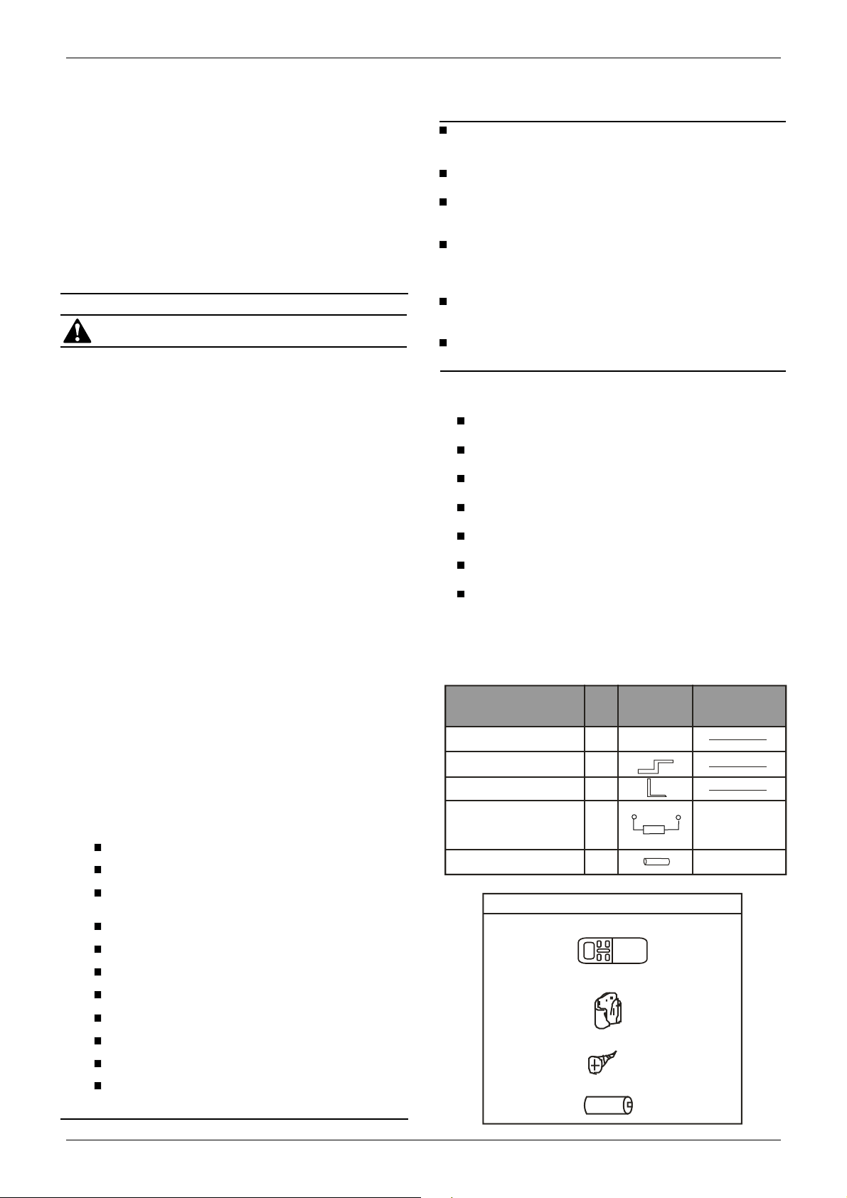
Please check whether the following fittings are of full scope.
If there are some spare fittings , please restore them carefully
Name of
Accessories
Installation manual
Hook
Hanging arm
Network matching wire
Drainage pipe
ALLATION INFORMATION
o install properly, please read this "installation manual" at
ALLATION ORDER
Select the location;
Install the indoor unit;
Install the outdoor unit;
Install the connecting pipe ;
Connect the drain pipe;
Wiring;
T
est operation.
TTACHED FITTINGS
ty
Q
Remote controller & Its Frame
1
. Remote controller .....................................1
2. Remote controller holder..........................1
3. Mounting screw (ST2.9x10-C-H)..............2
4. Alkaline dry battery(AM4) .........................2
(This manual)
1
2
2
1
1
Outline
Usage
The indoor unit which at the
terminal of communication system should connect a impedance between port P
d port Q.
Drainage
.
an-
2
Installation manual
Ceiling Floor
Mounting screw B
ST2.9x10-C-H
Remote controller
holder
Remote
controller
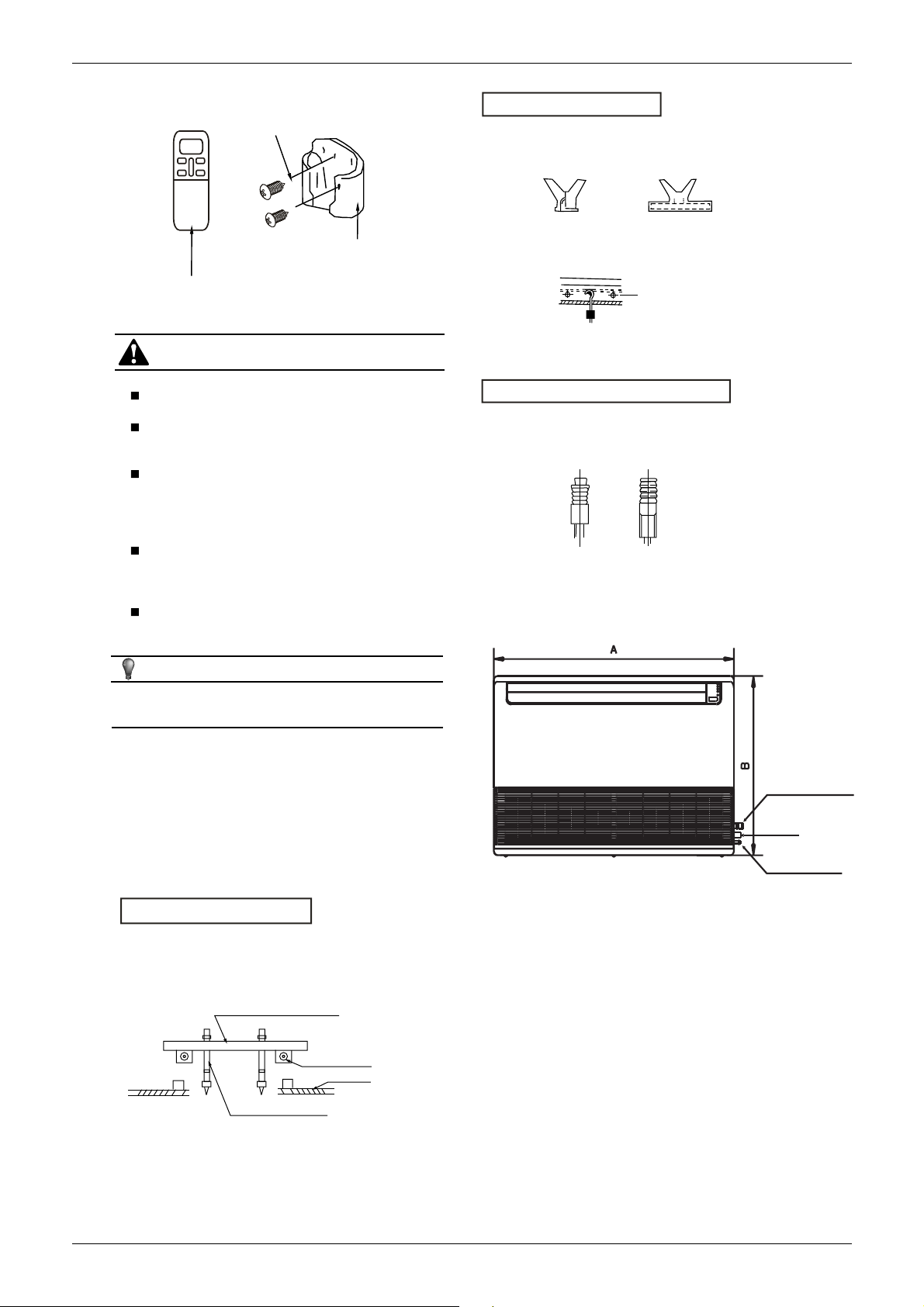
Fig.3-1
CAUTION
Never throw or beat the controller
Before installation, operate the remote controller
to determine its location in a reception range.
Keep the remote controller at least 1m apart from
the nearest
necessary
TV set or stereo equipment. (it is
to
prevent image disturbances or
noise interferences.)
Do not install the remote controller in a place
exposed to direct sunlight or close to a heating
source, such as a stove.
Note that the positive and negative poles are
right positions when loading batteries.
.
NEW CONCRETE BRICKS
Inlaying or embedding the screw bolts.
(Blade shape
insertion)
Embedding screw bolt
(Pipe hanging and embedding screw bolt)
FOR ORIGINAL
CONCRETE BRICKS
Install the hanging hook with expansible bolt into the concrete
deep to 45~50mm to prevent loose.
4.2 W
all Mounting Installation
(Slide insertion)
Fig.4-2
Steel bar
Fig.4-3
Fig.4-4
NOTE
This manual is subject to changes due to technological
improvement without further notices.
4. INDOOR UNIT INST
ALLATION
4.1 The units may be mounted vertically, provided that
the correct clearances for positioning are maintained.
(Refer to Fig. 4-1 )
WOODEN CONSTRUCTION
Put the square timber traversely overthe roof beam, then install
the hanging screw bolts.
Timber over the beam
Roof beam
Ceiling
Hanging screw bolts
Fig.4-1
I. Connecting point of
refrigerant pipe
(I. gas side)
Drain point
J.
Connecting point of
refrigerant pipe
(J. Liquid side)
Fig.
4-5
3
Installation manual
Fig.
4-6
Ceiling Floor
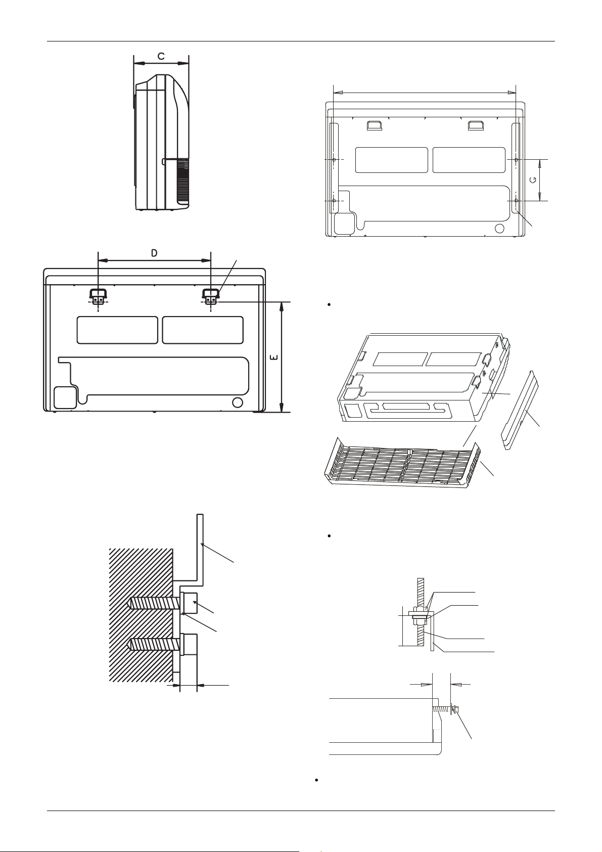
4.3 Ceiling Installation
F
Hanging arm
Hook
Fig. 4-7
1.Fix the hook with tapping screw onto the wall.(Refer to Fig. 4-8)
Hook
Fig.4-9
Remove the side board and the grille.(Refer to Fig. 4-10)
(For models 140 and 160, do not remove the grille.)
Side board
Grille
Fig. 4-10
Locate the hanging arm on the hanging screw bolt.
(Refer to Fig. 4-1
1)
Prepare the mounting bolts on the unit.( Refer to Fig. 4-12)
2.Hang
the indoor unit on the hook.
apping screw
T
W
asher
<6mm
Fig. 4-8
Screw nut
W
20~25mm
asher
Hanging
screw bolt
Hanging arm
8~13mm
INDOOR UNIT
Mounting bolt(max.40mm)
Hang the unit on the hanging arm by sliding backward. Securely
tighten the mounting bolts on both sides.(Refer to Fig. 4-13)
4
Fig.4-1
Fig. 4-12
1
 Loading...