

mundoclima CL23380, CL23383, CL23390, CL23394 Installation Manual
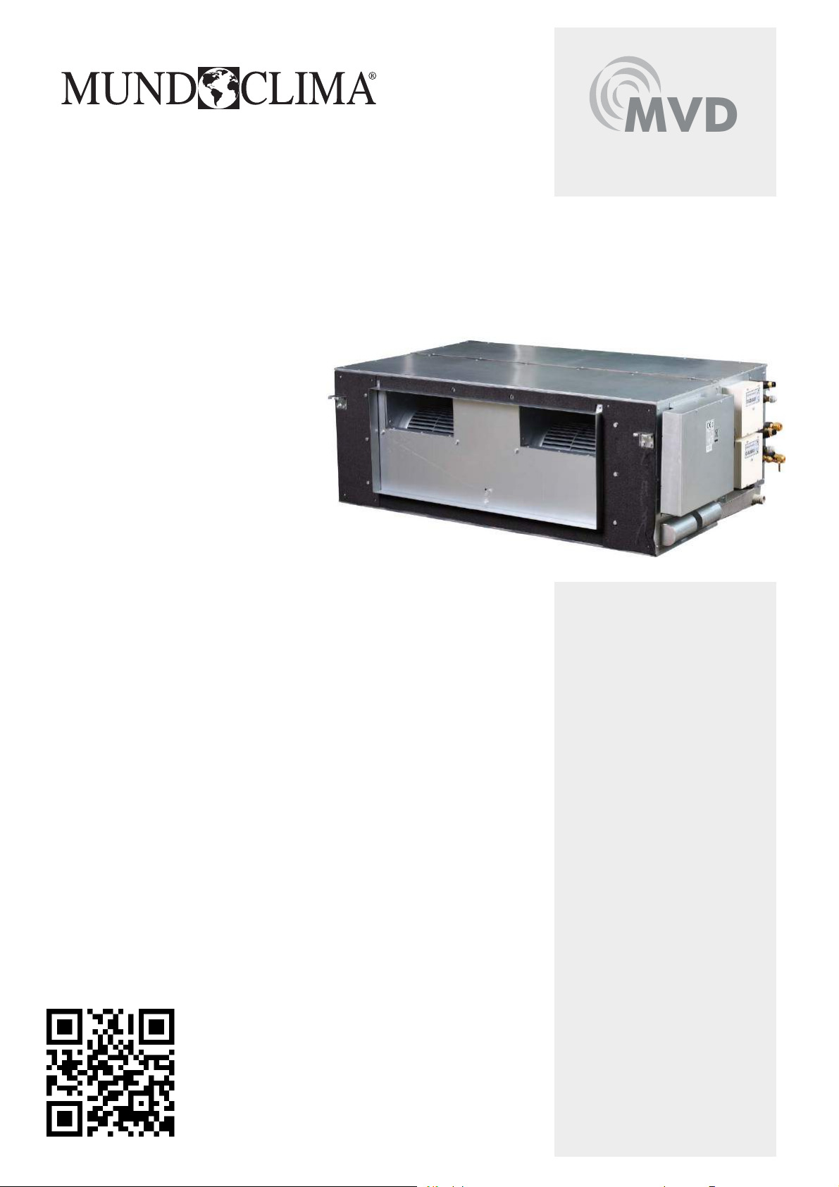
MVD
High Pressure Duct MVD DC
Installation manual
www.mundoclima.com
CL23380 to CL23383
English
Installation manual High pressure duct
CONTENTS P
INSTALLATION PRECAUTION...............................................................1
INSTALLATION PLACE.........................................................................1
ACCESSORIES......................................................................................2
INDOOR UNIT INSTALLATION ..............................................................2
INSTALLATION SPACE.......................................................................10
REFRIGERANT PIPE............................................................................10
DUCT DESIGN....................................................................................11
INSTALL THE CONNECTING PIPE.....................................................13
REFRIGERANT PIPE CONNECTION...................................................14
CONNECT THE DRAIN PIPE..............................................................15
WIRING..............................................................................................16
CONTROL...........................................................................................17
TROUBLE SHOOTING.........................................................................20
INSTALL ELECTRICTHROTTLE PART..................................................21
INSTALL BRANCH PIPE.....................................................................21
TEST OPERATION..............................................................................22
1. INSTALLA
To install properly
TION PRECAUTION
, please read this manual at first.
AGE
If the supply cord is damaged, it must be replaced by the
manufacturer or its service agent or a similarly qualified person
in order to avoid a hazard.
An all-pole disconnection switch having a contact separation of
at least 3mm in all poles should be connected in fixed wiring.
The appliance shall be installed in accordance with national
wiring regulations.
The temperature of refrigerant circuit will be high, please keep
the interconnection cable away from the copper tube.
An all-pole disconnection device which has at least 3mm
separation distance in all pole and a residual current
device(RCD) with the rating of above 10mA
in the fixed wiring according to the national rule.
The power cord type designation is H05RN-R/H07RN-F or above.
shall be incorporated
2. INSTALLATION PLACE
Indoor Unit
●
Enough room for installation and maintenance.
●
The ceiling is horizontal and it can afford the weight of the indoor
unit.
The air conditioner must be installed by qualified persons.
When installing the indoor unit or its tubing, please follow this
manual as strictly as possible.
When all the installation work is finished, please turn on the power
only after a thorough check.
No further announcement if there is any change of this manual
caused by product improvement.
NOTE
The installor
and maintain the air-conditioner, as well as remind users to
carefully read and keep both Installation Manual and Owner's
Manual well.
should illustrate to users how to correctly use
CAUTION
DISPOSAL˖Do not dispose this product as unsorted municipal
waste. Collection of such waste separately for special treatment
is necessary.
●
The air inlet and outlet are not impeded and does not af
outdoor air too much.
●
The air flow can reach every part of the room.
●
The connecting pipe and drainpipe can be easily extracted out.
●
There is no direct radiation from heat source.
Outdoor Unit
●
Enough room for installation and maintenance.
●
The air inlet and outlet are not impeded and does not af
outdoor air too much.
●
Dry and well ventilated place.
●
The
supporter is flat and horizontal and can afford the weigh of
outdoor unit, without noise and vibration.
●
The noise and the outlet air will not influence your neighbor.
●
No combustible gas.
●
Place convenient for piping and wiring.
Please keep away from the following places, or malfunction may
●
be caused.(if unavoidable, please consult the professionals):
fected by
fected by
This appliance is not intended for use by persons (including
children) with reduced physical, sensory or mental capabilities,
or lack of esperience and knowledge ,unless they have been
given supervision or instruction concerning use of the appliance
by a person responsible for their safety
Children should be supervised to ensure that they do not play
with the appliance.
Disconnect the power supply before cleaning and maintenance.
The appliance must be installed 2,3m above floor.
The appliance shall not be installed in the laundry.
.
There is mineral oil like the oil of cutting machine.
●
There is much salty air. (Near the coast)
●
There is caustic gas such as sulfuric gas. (Near the hotspring.)
●
Factory where the voltage fluctuate greatly.
In the car or in the cabin.
●
In the kitchen or a place full of oil steam.
●
There is strong electromagnetic wave.
●
1
Installation manual
●
There is combustible gas or materials.
●
There is much evaporating acid or alkaline gas.
●
Other special areas.
●
Notes Before Installation
Select the correct carry-in path.
Move this unit as originally packaged as possible.
●
If the air conditioner is installed on a metal part of the building, it
●
must be electrically insulated according to the relevant standards
to electrical appliances.
●
●
Avoid installing it in a narrow sapce which has a high requirement
to noise.
NOTE
Remark per
For to prevent flicker impressions during the start of the
compressor (technical process), following installation
conditions apply.
●
The power connection for the air conditioner has to be done
at the main power distribution.The distribution has to be of
a low impedance, normally the required impedance reaches
at a 32A fusing point.
●
No other equipment has to be connected with this power
line.
●
For detailed installation acceptance, please refer to your
contract with the power supplier if restrictions do apply for
products like washing machines, air conditioners or
electrical ovens.
For power
●
plate of the product.
EMC Directive 89/336/EEC
details of the air conditioner, refer to the rating
High pressure duct
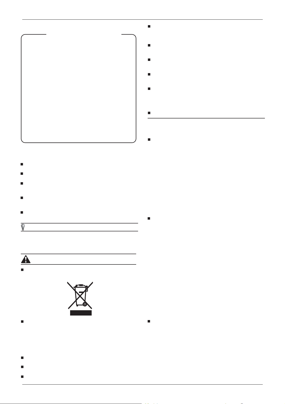
The following are selectable accessories
Remote controller & Its Frame
Remote controller....................................1
1.
2. Remote controller holder.........................1
3. Mounting screw
(ST2.9x10-C-H)................................ ........2
4. Alkaline dry battery(AM4)
..................................................................2
3
Mounting screw
1
ote
Rem
controller
Cautions on remote controller installation
●
Never throw or beat the controller.
●
Before
installation, operate the remote controller to determine
its location in a reception range.
Keep the remote controller at least 1m apart from the nearest
●
TV set or stereo equipment. (It is necessary to prevent
image disturbances or noise interferences.)
2
Remote controller
ho lder
Fig.3-1
For any question contact your local dealer.
●
3. ACCESSORIES
Table.3-1
Nam
e of
Accessories
Inst
allation manual
Wire controller
Pipe insulation material
Water outlet joint
Clasp
Water connecting pipe
Adhesive tape
for seal
Network matching wire
Copper nut
7.1-16.0
20.0-28.0
7.1-16.0
20.0-28.0
7.1-16.0
20.0-28.0
Q‘t
1
1
2
4
1
1
1
1
1
2
y
1
Outl
ine
(T
his manual)
Usag
e
Wire
control the
air-conditioner
Heat insulation
For drainage
Chucking the joint which
connect the drain hose
and the outlet of indoor
unit
To connect drain pipe
To connect drain pipe
The indoor unit which at
the terminal of
communication system
should connect a
impedance between port
P and port Q
Use for pipe connection
of engineering installation
●
Do not install the remote controller in a place exposed to
direct sunlight or close to a heatingsource, such as a stove.
Note that the positive and negative poles are in right positions
when loading batteries.
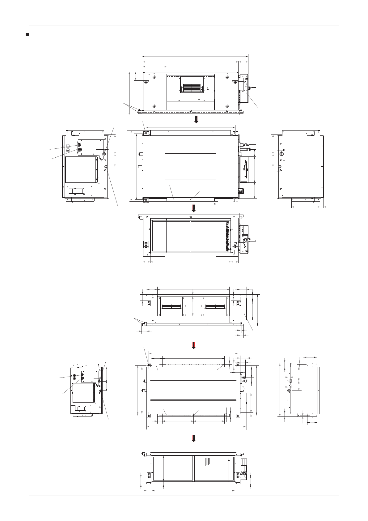
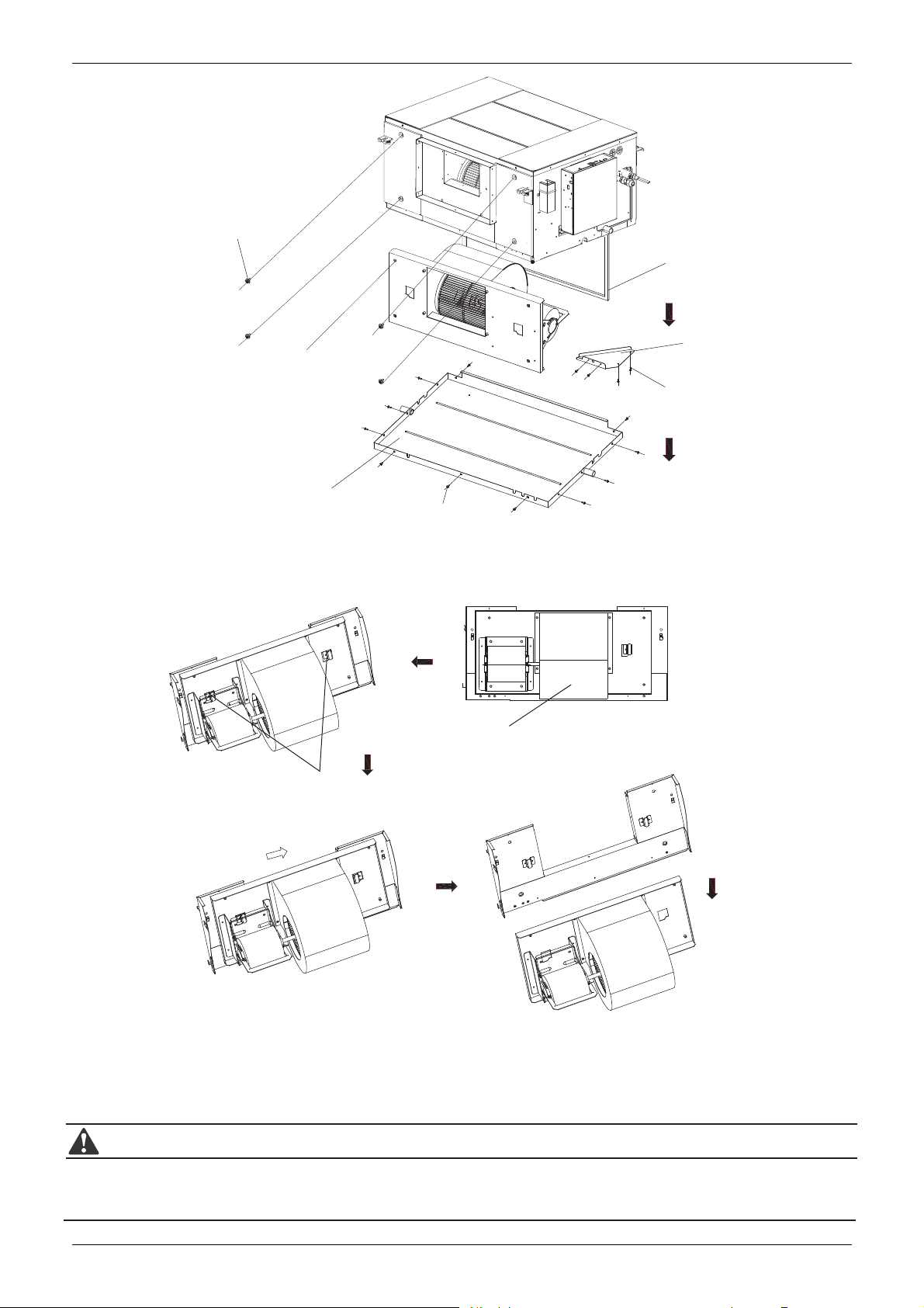
4. INDOOR UNIT INSTALLA
Installing Φ10 Hanging Screw Bolts (4 Bolts)
refer
Please
measurement between the screw bolts.
Please install with screw bolts.
The handling to the ceiling varies from the constructions, consult
the construction personnels for the specific procedures.
The size of the ceiling to be handledDo keep the ceiling flat. Con-
●
solidate the roof beam for possible vibration.
●
Cut off the roof beam.
Strengthen the place cut off, and consolidate the roof beam.
●
Carry out the pipe and line operation in the ceiling after
finishing the installation of the main body. While choosing where
to start the operation, determine the direction of the pipes to be
drawn out. Especially in case there is a ceiling, position the
refrigerant pipes, drain pipes, indoor & outdoor lines to the connection places before hanging up the machine.
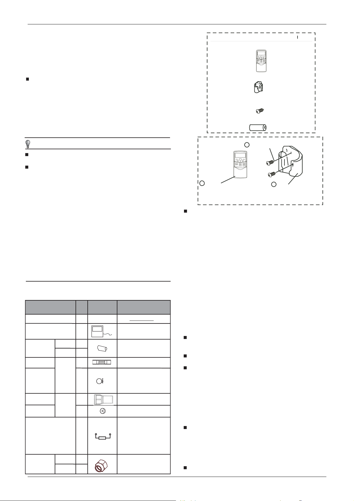
The installation of hanging screw bolts.
to the following figure for the distance
TION
2
Installation manual
Wooden construction
Put the square timber traversely over the roof beam, then
install the hanging screw bolts. (Refer to
Timber over the beam
Roof beam
Hanging screw bolt s
New concrete bricks
Inlaying or embedding the screw bolts (Refer to
Ceiling
Fig.4-1
)
Fig.4-1
Fig.4-2)
High pressure duct
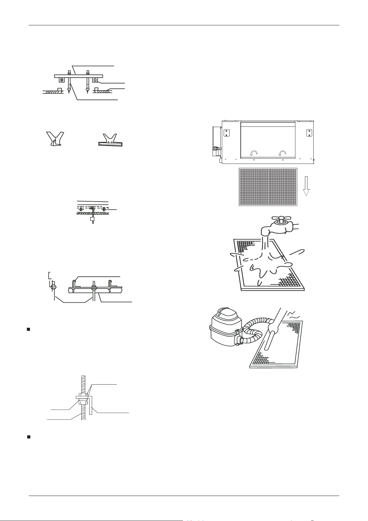
Take out the air-in grill.
ĸ
Ĺ
Dismantle the air filter
Clean the air filter (Vacuum cleaner or pure water may be
ĺ
used to clean the air filter. If the dust accumulation is too
heavy , please use soft brush and mild detergent to clean it
and dry out in cool place).
The air-in side should face down when using water.
Ļ
(See Fig.4-7)
ļ
The air-in side should face up when using vacuum cleaner.
(See Fig.4-8)
Blade shape insertion Slide insertion
Fig.4-2
For original concrete bricks
Use embeding screw bold, crock and stick harmness (refer
to
Fig.4-3)
Steel bar
bedding screw bolt
Em
(Pipe hanging and embedding screw bolt)
Fig.4-3
Steel roof beam structre
Install and use directly the supporting angle steel. (refer to
Fig.4-4)
Ha
Hanging bolts
nging screw bolt
Supporting
steel
angle
Fig.4-4
Overhanging the indoor unit
Fig.4-6
Fig.4-7
●
Overhang the
indoor unit onto the hanging screw bolts with
block.
●
Position the indoor unit in a flat level by using the level indicator,
unless it may cause leakage.
Screw nut
washer
Hanging
screw bolt
Overhang part
Fig.4-5
Install the main body
●
Installing the dust proof net and canvas air passage
Open the air-in grill
ķ
Anti-clockwise the
bolts as indicated in follow figure
sketch.Then pull down the air-in grill.
Fig.4-8
●
Pipe Connection
The static
pressure outside the unit is 200Pa , the length of
the air pipe attached is determined by this parameter.
●
The positioning of ceiling hole and indoor unit and hanging
screw bolts
Routine method of installation: the size of installation for indoor
ķ
unit following Fig.4-9
ĸ
Please install with Φ10 hanging screw bolts.
Carry out the pipe and line operation in the ceiling after finishing
Ĺ
the installation of the main body. While choosing where to start
the operation,
determine the direction of the position the
refrigerant pipes, drain pipes, indoor & outdoor lines and linecontrolled lines to the connection places before.
3
Installation manual
The positioning of ceiling hole and indoor unit and hanging screw bolts
routine method of installation: the size of installation for indoor unit following the Fig.4--9 and Fig.4-10
High pressure duct
Unit: mm
7.1~11.2 kW
REFRIGERANT-PIPE FLANED
CONNECTION Φ9.52(3/8)
REFRIGERANT-PIPE FLANED
CONNECTION Φ16(5/8)
952
214
85
420
PLASTIC COVER
CONNECTING POINT OF
DRAIN PIPE
189123
43
61
75
SAFETY DRAIN CONNECTING PIPE
4-12*25 OBLONG SUSPENTION BOLT HOLES
690
642
AIR OUTLET DUCT FLANGE
856
AIR INTAKE
800
4-Φ5HOLES FOR AIR
INTAKE DUCT CONNECTION
AIR OUTLET
86
ELECTRICAL CONTROL BOX
189123
44253155
26
255 33
14~16 kW
REFRIGERANT-PIPE FLANED
CONNECTION Φ9.52(3/8)
REFRIGERANT-PIPE FLANED
CONNECTION Φ16(5/8)
339
Fig.4-9
72265
135 88
82
PLASTIC COVER
68
4-12*25 OBLONG SUSPENTION BOLT HOLES
CONNECTING POINT OF
DRAIN PIPE
189123
43
638
61
75
SAFETY DRAIN CONNECTING PIPE
137
AIR INTAKE DUCT FLANGE
600
AIR OUTLET DUCT FLANGE
65
400
930
29
249
AIR INTAKE
8
114
800
4-Φ5 HOLES FOR AIR
OUTLET DUCT CONNECTION
6-Φ5 HOLES FOR
AIR
DUCT CONNECTION
OUTLET
400
1300
65
Unit: mm
82
15
50
37
15
56
420
270
24
ELECTRICAL
CONTROL
46
90
69
136
14
253
17
BOX
169
15
52
179
28
11
638
691
123
35
125
136
AIR OUTLET
339
82
31
64
1073
82
Fig.4-10
4
Installation manual
High pressure duct
The method of installation: Adopt following method if the air-conditioning’
installtionsite.
7.1~11.2 kW
s size of installationsite is limited and the indoor unit can’t put into the
1
Fig.4-1
ray
Water T
1. The whole unit status show as Fig.4-11
2. Remove the all 1
3. Take off the tray along the direction of the arrow show in Fig.4-12
4. Clean the tray and evaporator.
5. Re-install the unit follow the reverse above orders.
screw
from fixed Safety Drain T
1
, and then take off the tray as figure showed in Fig.5-11.
ray
CAUTION
Safety Drain T
ray
Position A
Position B
11-Screw
Fig.4-12
1. Please shut down the unit and cut off power cable before maintain the motor.
2. Don’t heavy pull the foam tray, when dismounting; otherwise the foam tray would break.
5
Installation manual
Maintenance of motor:
4 Bolts
For fixing the fan assembly
High pressure duct
Filter
Inside of structure
Side view of fan assembly
installation state
Motor Asseembly
Safety Drain Tray
Pothook
11-Screw
For fixing the satety drain tray
Front view of fan assembly installation state
Scroll
Fortified panel
4 Screw
For fixing the reinforced panel
Fig.4-13
Fan assembly should
push horizontally to the
end (about 18mm), and
then take of
1. Refer to Fig.4-13, remove all 1
2. Refer to Fig.4-13, remove all 4 bolts from reinforced panel, and take off the panel.
3. Refer to Fig.4-13, remove all 4 bolts from fan assembly, see Fig.4-14, according to which orders to take off the fan assembly.
4. Refer to Fig.4-14, horizontal pushing the fan assembly, until it cannot not move any further, and then lift up slightly and take down to remove it.
5. After motor maintenance, reinstall the fan assemblies as per the reverse above orders. And connect the motor with electric control box,
as motor with power cable of capacity.
f it.
Move 18mm
Move
The state after fan assembly is taken off
1 bolts from safety drain tray, and take off the safety drain tray.
CAUTION
1. Please shut down the unit and cut off power cable before maintain the motor.
2. Before dismount the fan assembly, you must remove the motor and electric control box, as well as connective wires between
motor and capacity assembly.
3. Fan subassembly is very heavy, please be careful during maintaining, otherwise physical injury would be caused.
6
Fig.4-14
Installation manual
14~16 kW
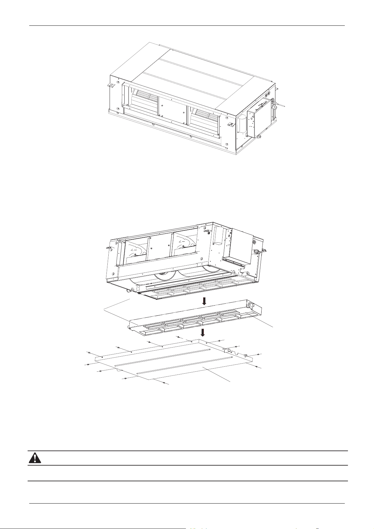
High pressure duct
g.4-15
Fi
er Tray
Wat
1.
The whole unit status show as Fig.4-15.
2. Remove the all 11
3. Take off the tray along the direction of the arrow show in Fig.4-16.
4. Clean the tray and evaporator.
5. Re-install the unit follow the reverse above orders.
1. Please shut down the unit and cut off power cable before maintain the motor.
2. Don’t heavy pull the foam tray, when dismounting; otherwise the foam tray would break.
scre
f
w
om fixed Safety Drain Tray, and then take off the tray as figure showed in Fig.4-16.
r
CAUT
ION
12 S
For fixing the safety drain tray
Safety Drain Tray
ition A
Pos
Position B
crew
Fi
g.4-16
7
 Loading...