

mundoclima Bibloc Aerotherm V17 Service Manual
BIBLOC UNIT - AEROTHERM V17
Service Manual
www.mundoclima.com
Thank you very much for purchasing our product.
Before using your unit, please read this manual carefully
and keep it for future reference.
SO30160 to SO30172
English

Service Manual
Aerotherm V17
Content
1. General Information ..................................................................................... 3
1.1 Measurements ............................................................................... 3
1.2 External appearance ..................................................................... 4
1.3 Nomenclature ................................ ................................ ................ 5
2. Features ....................................................................................................... 6
3. Specifications ............................................................................................... 8
3.1 220-240/1/50 products ................................................................... 8
3.2 380-415/3/50 products ................................................................. 12
3.3 Hydronic box ............................................................................... 14
4. Operation range ......................................................................................... 15
5. Sound pressure levels ............................................................................... 16
6. Accessories ................................................................................................ 17
6.1 Accessories for outdoor unit ........................................................ 17
6.2 Accessories for hydronic box ....................................................... 17
7. Performance data ...................................................................................... 18
7.1 Heating capacity for 220-240/1/50 products ................................ 18
7.2 Heating capacity for 380-415/3/50 products ................................ 25
8. System diagram ......................................................................................... 28
8.1 System diagram for outdoor unit ................................................. 28
8.2 System diagram for hydronic box ................................................ 29
9. Wiring diagrams ......................................................................................... 30
9.1 Wring diagram for outdoor unit .................................................... 30
9.2 Wring diagram for hydronic box ................................................... 34
10. Overview of the unit ................................................................................. 36
10.1 Overview of the outdoor unit ...................................................... 36
10.2 Overview of hydronic box .......................................................... 37
10.3 Electric box lay out for outdoor unit ........................................... 40
10.4 Electric box lay out for hydronic box .......................................... 46
1

Service Manual
Aerotherm V17
1. Installation ................................................................................................ 47
1
11.1 Installation for outdoor unit ........................................................ 47
11. 2 Installation for hydronic box ...................................................... 51
11.3 Refrigerant pipework .................................................................. 54
11.4 Electrical wiring .......................................................................... 57
11.4 Water pipework .......................................................................... 59
11.5 Fill the water .............................................................................. 67
11.6 Piping insulation ......................................................................... 67
11.7 Field wiring ................................................................................ 67
12. Start-up and configuration ........................................................................ 78
12.1 Climate related curves ............................................................... 78
12.2 DIP switch settings .................................................................... 81
12.3 Initial start-up at low outdoor ambient temperatures .................. 81
12.4 Pre-operation checks ................................................................. 82
12.5 Powering up the unit .................................................................. 83
12.6 Setting the pump speed ............................................................. 83
12.7 Failure diagnosis at the moment of first installation ................... 86
12.8 Field setting ............................................................................... 87
12.9 Test run and final check ........................................................... 106
13. Maintenance and service ....................................................................... 107
14. Troubleshooting ..................................................................................... 109
14.1 General symptoms description ................................................ 109
14.2 Parameters check.................................................................... 111
14.3 Error codes and troubleshooting ............................................. 115
2
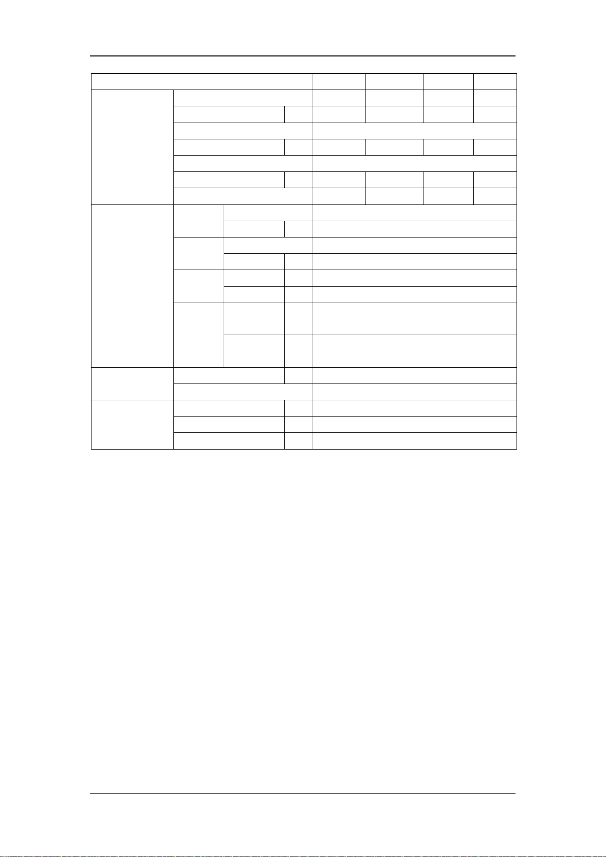
1. General Information
Model name
Dimension
(mm)
Net/Gross
weight (kg)
Power supply
Width: 960
Height: 860
Depth: 380
60/72
220~240-50Hz 1Ph
76/88
220~240-50Hz 1Ph
99/112
220~240-50Hz 1Ph
Width: 900
Height: 1327
Depth: 400
115/128
380~415-50Hz 3Ph
Model name
Dimension
(mm)
Net/Gross
weight (kg)
Power supply
Width: 400
Height: 865
Depth: 427
51/57
220~240-50Hz 1Ph
Width: 400
Height: 865
Depth: 427
54/60
220~240-50Hz 1Ph
Width: 400
Height: 865
Depth: 427
54/60
380~415-50Hz 3Ph
Service Manual
Aerotherm V17
1.1 Measurements
1.1.1 Outdoor units
UE BIBLOC AEROTHERM V17 (4KW)
UE BIBLOC AEROTHERM V17 (6KW)
Width: 1075
UE BIBLOC AEROTHERM V17 (8KW)
UE BIBLOC AEROTHERM V17 (10KW)
UE BIBLOC AEROTHERM V17 (12KW)
UE BIBLOC AEROTHERM V17 (14KW)
UE BIBLOC AEROTHERM V17 (16KW)
UE BIBLOC AEROTHERM V17 (12KW)
(TRIF.)
UE BIBLOC AEROTHERM V17 (14KW)
(TRIF.)
UE BIBLOC AEROTHERM V17 (16KW)
(TRIF.)
1.1.2 Hydronic box
Height: 965
Depth: 395
Width: 900
Height: 1327
Depth: 400
UI BIBLOC AEROTHERM V17 (4 ~ 8KW)
UI BIBLOC AEROTHERM V17 (10 ~ 16KW)
UI BIBLOC AEROTHERM V17 (10 ~ 16KW)
(TRIF.)
3
Service Manual
Aerotherm V17
1.2 External appearance
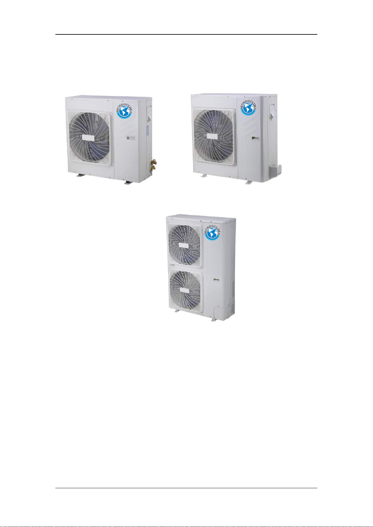
1.2.1 Outdoor units
4/6kW 8kW
1Ph 10-16kW & 3Ph 12-16kW
4
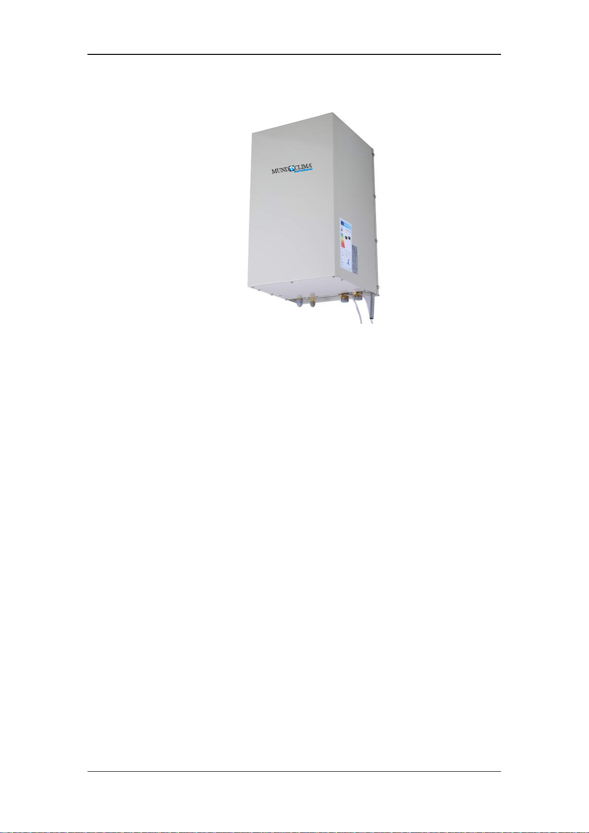
1.2.1 Hydronic box
Service Manual
Aerotherm V17
5
2. Features
Service Manual
Aerotherm V17
Outdoor unit
Compact structure, independent hydronic box, flexible installation.
Refrigerant pipes run indoors from the outdoor unit, no need extra
insulation of water piping to protect from freezing up.
No need extra refrigerant within 10m refrigerant pipe length.
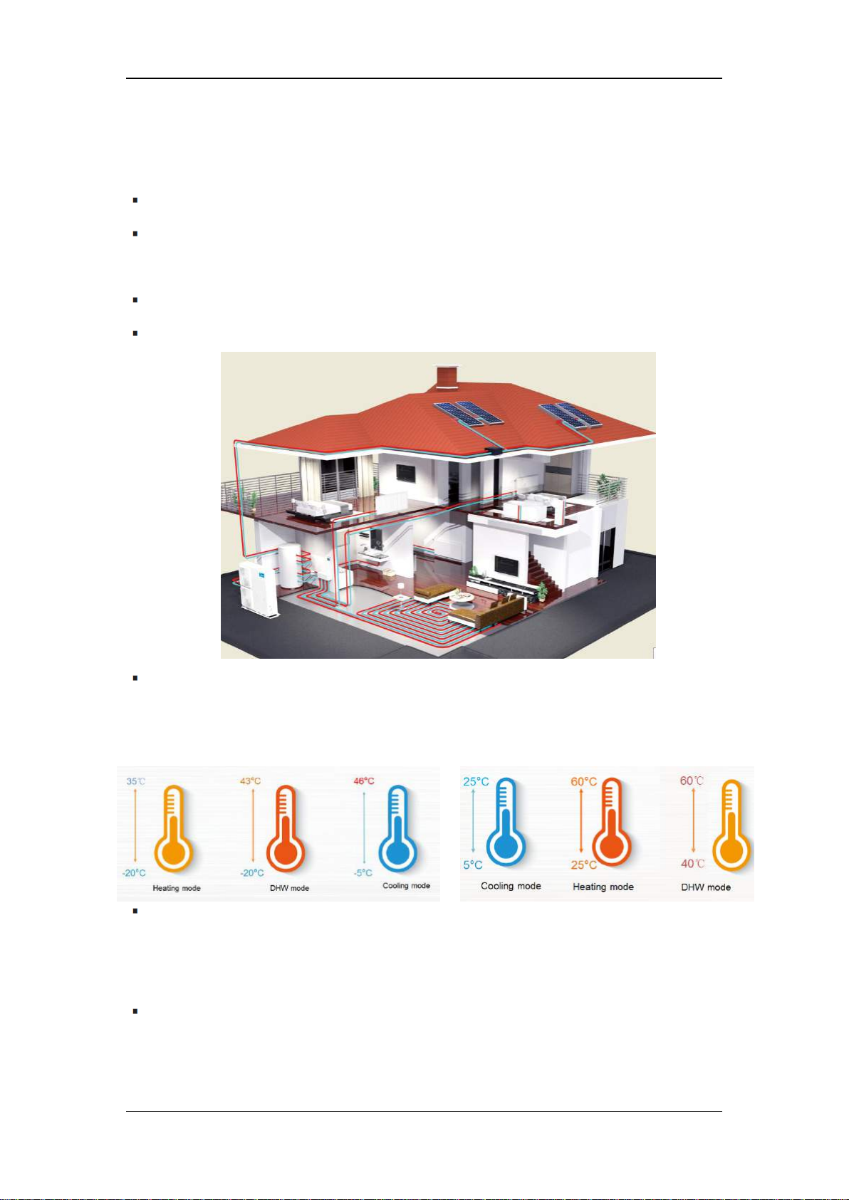
Heating, cooling & domestic hot water, total heat solution
Wide operation ambient temperature range & Wide water outlet
temperature range
Ambient Temp. range Water outlet Temp. range
DC inverter technology to guarantee optimal operational reliability and
efficiency. Offers heating capacity of 80% at -7°C thanks to the large heat
exchanger and large compressor.
Compatible with additional heat sources (AHS), including solar energy,
fuel boiler, gas boiler and so on. AHS can work together with heat pump or
alternative for space heating and domestic hot water dependent on the
system control.
6
Service Manual
Aerotherm V17
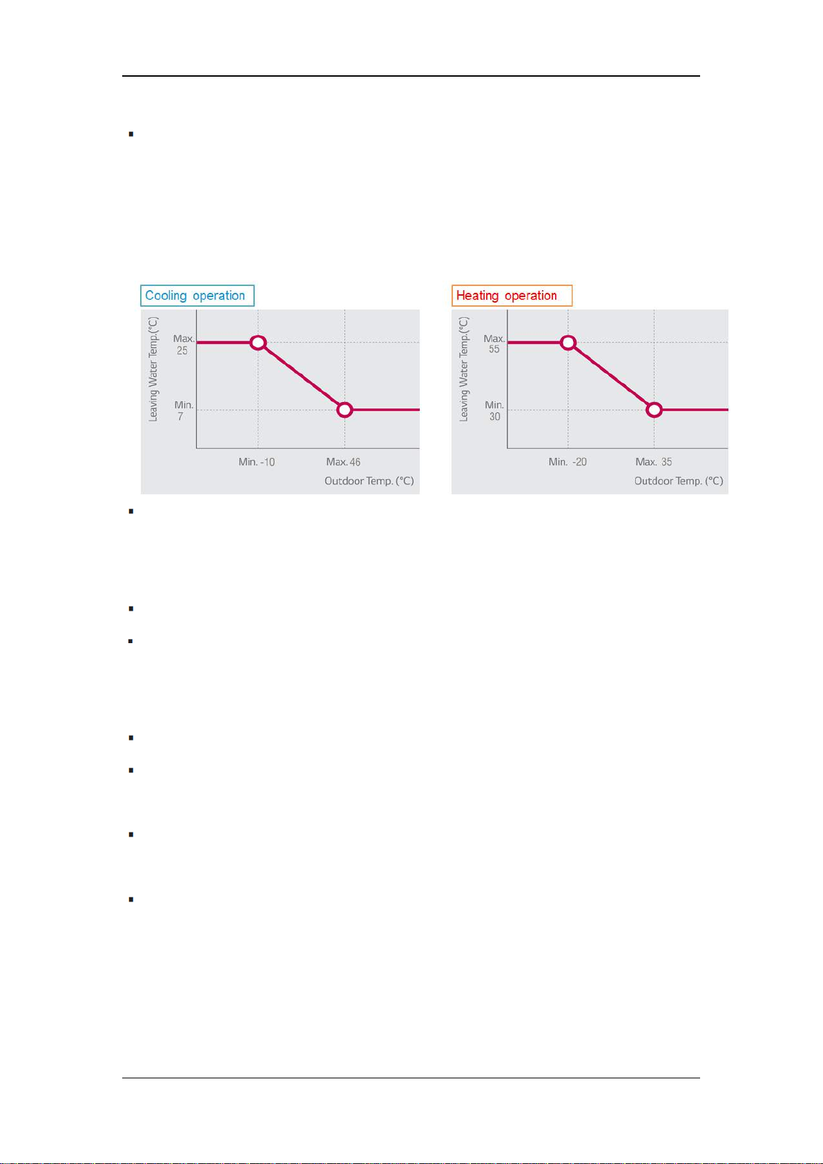
Weather dependent operation with climate correlation to ensure absolute
comfort
Climate correlation curve curves for choice. Once the curve is selected,
the unit set the outlet water temperature automatically according to the
outdoor ambient temperature.
Two zones control for more flexibility
Temperature of each zone is separately controlled. Two zones control
reduces water pump cycle time and save energy.
Priority setting function and multi modes choice
Special functions such as air purge, preheating for floor and floor drying up
for special use
Independent hydronic box
All hydronic components are pre-assembled, easy for installation.
All parts are easy to reach for maintenance thanks to the rotatory electric
box design.
Backup E-heater for additional heating during extremely cold outdoor
temperatures. The capacity of E-heater is adjustable.
Standard drain pan in the hydronic box, no worry about condensate water.
7
Outdoor Split type (Bibloc)
Heating1
Capacity
kW
4.10
6.10
8.00
Rated input
kW
0.82
1.29
1.73
COP
5.00
4.73
4.62
Heating2
Capacity
kW
4.01
5.96
7.34
Rated input
kW
1.13
1.68
2.13
COP
3.55
3.55
3.45
Cooling1
kW
4.10
6.10
8.00
kW
0.79
1.31
1.78
5.19
4.66
4.49
Cooling2
kW
4.12
6.15
6.44
kW
1.30
2.08
2.24
3.17
2.96
2.88
Seasonal space heating energy eff.
Class (average climate general)
A++
A++
A++
A+
A+
A+
Power supply
V/Ph/Hz
220-240/1/50
Maximum Overcurrent Protection (MOP)
A
20.0
22.0
Minimum Circuit Amps (MCA)
A
18.0
20.0
Dimension (W×H×D)
mm
960×860×380
1075×965×395
Packing (W×H×D)
mm
1040×1000×430
1120×1100×435
Net/gross weight
kg
60/72
76/88
Sound pressure level3
Heating
dB(A)
62
64
Cooing
dB(A)
62
64
Compressor
Brand
Mitsubishi
GMCC
Model
SNB172FJFMC
ATF250D22UMT
Type
Twin rotary DC inverter
Poles 6 6
6
Speed
10~130rps
10~130rps
12~120rps
Max.
frequency
Hz
5400
5400
7645
Outdoor fan
Brand
Panisonic/Nidec/WELLING
Motor type
Brushless DC motor
Model
ZKSP-72-8-1
ZKSP-170-8-1
Number of fans
1 1 1
Air flow
m3/h
3180
3180
5120
Service Manual
Aerotherm V17
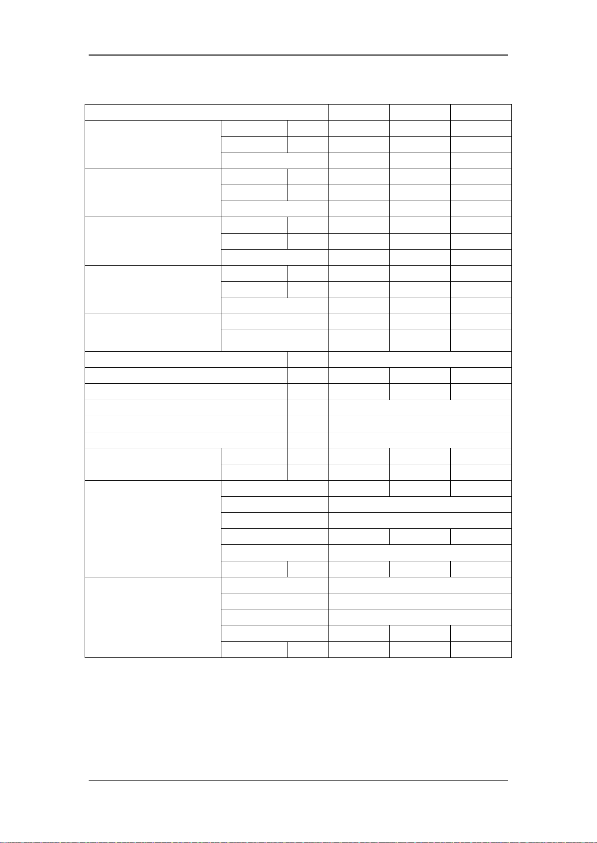
3. Specifications
3.1 220-240/1/50 products
4KW 6KW 8KW
Capacity
Rated input
EER
Capacity
Rated input
EER
Water outlet @ 35℃
Water outlet @ 55℃
8
Air side heat exchanger
Number of rows
2 2 2
Tube pitch(a)x row pitch(b)
mm
25.4/22
25.4/22
25.4/22
Tube dia. and type
Φ9.52 inner grooved copper
Fin space
mm
1.4
1.4
1.8
Fin type (code)
Hydrophilic aluminum
Coil length x height
mm
760×813
760×813
880×914
Number of circuits
5 5
8
Piping connections
Liquid
Type
Flaring
Flaring
Dia.(OD)
mm
Φ9.5
Φ9.5
Flaring
Flaring
mm
Φ15.9
Φ15.9
m 2 2
m
20
30
m
10
20
m 8 15
Refrigerant
kg
R410A/2.5
R410A/2.8
Electric expansion valve
Ambient temperature
range
Cooling ℃ -5~46
-5~46
Heating ℃ -20~35
-20~35
Sanitary hot water
℃
-20~43
-20~43
4KW 6KW 8KW
Outdoor Split type (Bibloc)
Service Manual
Aerotherm V17
Gas
Piping length
Installation
height
difference
Type/Quantity
Throttle type
MOP: Maximum Overcurrent Protection MCA: Minimum Circuit Amps
Nominal capacity is based on the following conditions:
1.Evaporator air in 7℃ ℃85% R.H., Condenser water in/out 30/35℃
2.Evaporator air in 7℃ ℃85% R.H., Condenser water in/out 40/45℃
3.Condenser air in 35℃. Evaporator water in/out23/18℃
4.Condenser air in 35℃. Evaporator water in/out 12/7℃
5. At 1m in open field fan side (sound pressure)
6.The above data test reference standard EN14511:2013; EN14825:2013; EN50564:2011; EN12102:2011; (EU)
No:811:2013; (EU)No:813:2013; OJ 2014/C 207/02:2014
Type
Dia.(OD)
Min.
Max.
Outdoor unit upside
Outdoor unit downside
9

Heating1
Capacity
kW
10.00
12.10
14.00
15.50
Rated input
kW
2.17
2.74
3.39
3.82
COP
4.61
4.42
4.13
4.06
Heating2
Capacity
kW
10.12
11.85
14.05
16.05
Rated input
kW
2.93
3.48
4.41
5.03
COP
3.45
3.41
3.19
3.19
Cooling1
Capacity
kW
10.00
11.80
13.00
14.00
Rated input
kW
2.07
2.65
3.23
3.62
EER
4.83
4.45
4.02
3.87
Cooling2
9.39
11.02
12.49
12.85
3.26
4.17
5.07
5.39
2.88
2.64
2.46
2.38
Seasonal space heating
energy eff. Class
(average climate
general)
A++
A++
A++
A++
A+
A+
A+
A+
Power supply
220-240/1/50
Maximum Overcurrent Protection (MOP)
35
35
35
35
Minimum Circuit Amps (MCA)
A
30
30
32
32
Dimension (W×H×D)
mm
900×1327×400
Packing (W×H×D)
mm
1030×1457×435
Net/gross weight
kg
99/112
Sound pressure level3
Heating
dB(A)
65
66
69
71
Cooing
dB(A)
65
66
69
71
Compressor
Brand
GMCC
GMCC
GMCC
GMCC
Model
ATQ420D1UMU
Type
Twin rotary DC inverter
Poles 6 6 6 6
Speed
12~120rps
Max.
Hz
13000
13000
13000
13000
Outdoor fan
Brand
Panisonic/Nidec/WELLING
Motor type
Brushless DC motor
Model
ZKSP-100-8-1
Number of fans
2 2 2
2
Air flow
m3/h
6500
6500
6500
6500
Outdoor Split type (Bibloc)
Service Manual
Aerotherm V17
Capacity kW
Rated input kW
EER
Water outlet @ 35℃
Water outlet @ 55℃
10KW 12KW 14KW 16KW
V/Ph/Hz
A
10
Air side heat
exchanger
Number of rows
2 2 2
2
Tube pitch(a)x row pitch(b)
mm
25.4/22
25.4/22
25.4/22
25.4/22
Tube dia. and type
Φ9.52 inner grooved copper
Fin space
mm
1.6
1.6
1.6
1.6
Fin type (code)
Hydrophilic aluminum
Coil length x height
mm
845×1270
845×1270
845×1270
845×1270
Number of circuits
9 9 9
9
Piping connections
Liquid
Type
Flaring
Dia.(OD)
mm
Φ9.5
Flaring
mm
Φ15.9
m
2
m
50
m
30
m
25
Refrigerant
kg
R410A/3.9
Throttle type
Electric expansion valve
Ambient temperature
range
Cooling
℃
-5~46
Heating
℃
-20~35
Sanitary hot water
℃
-20~43
Outdoor Split type (Bibloc)
Service Manual
Aerotherm V17
10KW 12KW 14KW 16KW
Gas
Piping length
Installation
height
difference
Type/Quantity
MOP: Maximum Overcurrent Protection MCA: Minimum Circuit Amps
Nominal capacity is based on the following conditions:
1.Evaporator air in 7℃ ℃85% R.H., Condenser water in/out 30/35℃
2.Evaporator air in 7℃ ℃85% R.H., Condenser water in/out 40/45℃
3.Condenser air in 35℃. Evaporator water in/out23/18℃
4.Condenser air in 35℃. Evaporator water in/out 12/7℃
5. At 1m in open field fan side (sound pressure)
6. The above data test reference standard EN14511:2013; EN14825:2013; EN50564:2011; EN12102:2011; (EU)
No:811:2013; (EU)No:813:2013; OJ 2014/C 207/02:2014
Type
Dia.(OD)
Min.
Max.
Outdoor unit
upside
Outdoor unit
downside
11
Heating1
Capacity
kW
12.10
14.00
15.50
Rated input
kW
2.68
3.26
3.79
COP
4.51
4.29
4.09
Heating2
Capacity
kW
11.97
13.93
15.48
Rated input
kW
3.50
4.21
4.87
COP
3.42
3.31
3.18
Cooling1
Capacity
kW
12.10
13.00
14.00
kW
2.82
3.21
3.68
4.29
4.05
3.80
Cooling2
kW
11.70
12.53
12.91
kW
4.65
5.21
5.52
2.52
2.40
2.34
Seasonal space heating energy eff.
Class (average climate general)
A++
A++
A++
A+
A+
A+
Power supply
V/Ph/Hz
380-415/3/50
Maximum Overcurrent Protection (MOP)
A
18
18
18
Minimum Circuit Amps (MCA)
A
15
15
16
Dimension (W×H×D)
mm
900×1327×400
Packing (W×H×D)
mm
1030×1457×435
Net/gross weight
kg
115/128
Sound pressure level3
Heating
dB(A)
66
69
71
Cooing
dB(A)
66
69
71
Compressor
Brand
GMCC
GMCC
GMCC
Model
ATQ420D2UMU
Type
Twin rotary DC inverter
Poles 6 6
6
Speed
12~120rps
Max. frequency
Hz
13000
13000
13000
Outdoor fan
Brand
Panisonic/Nidec/WELLING
Motor type
Brushless DC motor
Model
ZKSP-100-8-1
Number of fans
2 2 2
Air flow
m3/h
6500
6500
6500
Outdoor Split type (Bibloc)
Service Manual
Aerotherm V17
3.2 380-415/3/50 products
Rated input
EER
Capacity
Rated input
EER
Water outlet @ 35℃
12KW 14KW 16KW
Water outlet @ 55℃
12
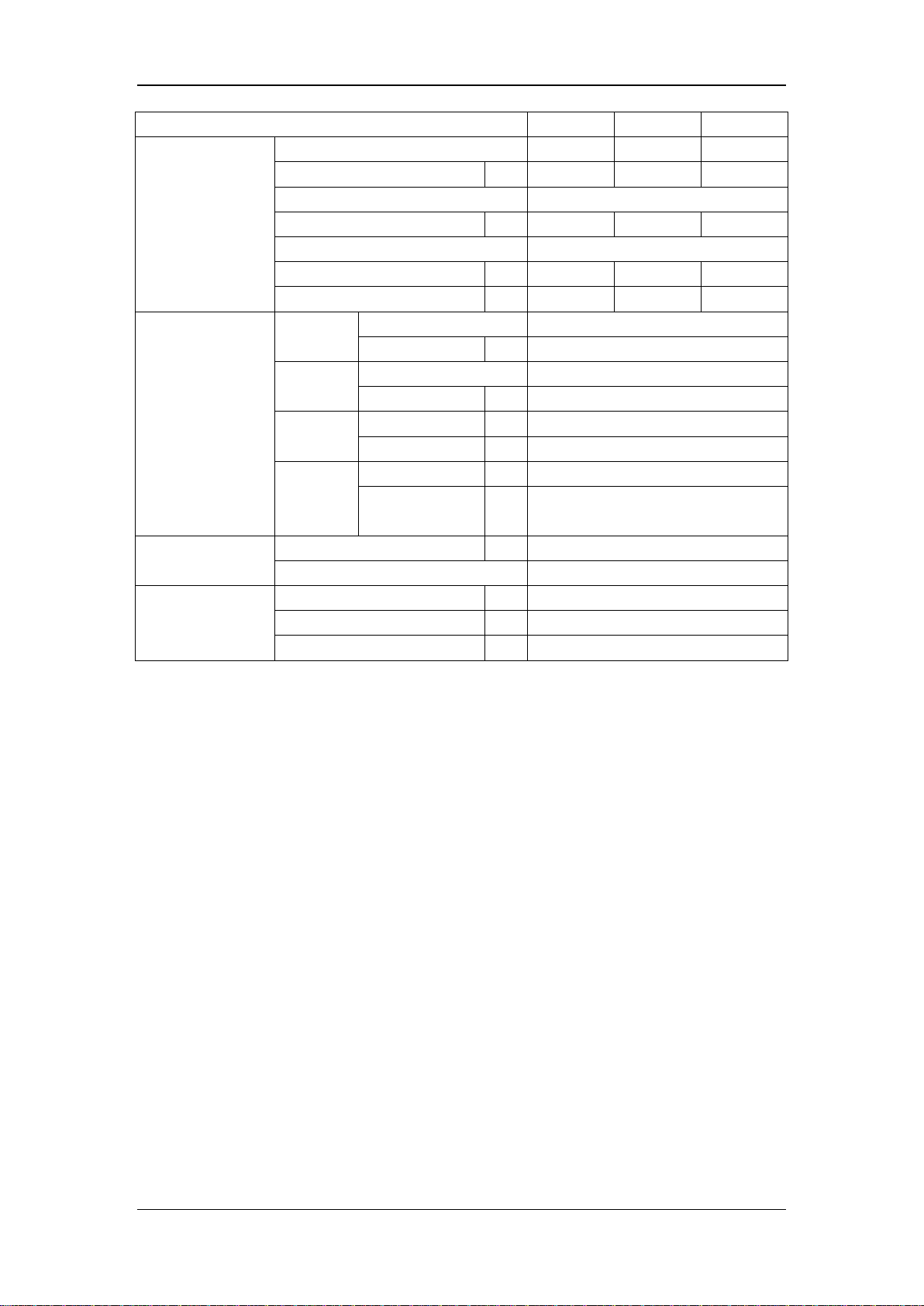
Air side heat exchanger
Number of rows
2 2 2
Tube pitch(a)x row pitch(b)
mm
25.4/22
25.4/22
25.4/22
Tube dia. and type
Φ9.52 inner grooved copper
Fin space
mm
1.6
1.6
1.6
Fin type (code)
Hydrophilic aluminum
Coil length x height
mm
845×1270
845×1270
845×1270
Number of circuits
9 9
9
Piping connections
Liquid
Type
Flaring
Dia.(OD)
mm
Φ9.5
Flaring
mm
Φ15.9
m
2
m
50
m
30
m
25
Refrigerant
kg
R410A/4.2
Electric expansion valve
Ambient temperature
range
Cooling
℃
-5~46
Heating
℃
-20~35
Sanitary hot water ℃ -20~43
Outdoor Split type (Bibloc)
Service Manual
Aerotherm V17
12KW 14KW 16KW
Gas
Piping length
Installation
height
difference
Type/Quantity
Throttle type
MOP: Maximum Overcurrent Protection MCA: Minimum Circuit Amps
Nominal capacity is based on the following conditions:
1.Evaporator air in 7℃ ℃85% R.H., Condenser water in/out 30/35℃
2.Evaporator air in 7℃ ℃85% R.H., Condenser water in/out 40/45℃
3.Condenser air in 35℃. Evaporator water in/out23/18℃
4.Condenser air in 35℃. Evaporator water in/out 12/7℃
5. At 1m in open field fan side (sound pressure)
6. The above data test reference standard EN14511:2013; EN14825:2013; EN50564:2011; EN12102:2011; (EU)
No:811:2013; (EU)No:813:2013; OJ 2014/C 207/02:2014
Type
Dia.(OD)
Min.
Max.
Outdoor unit upside
Outdoor unit
downside
13
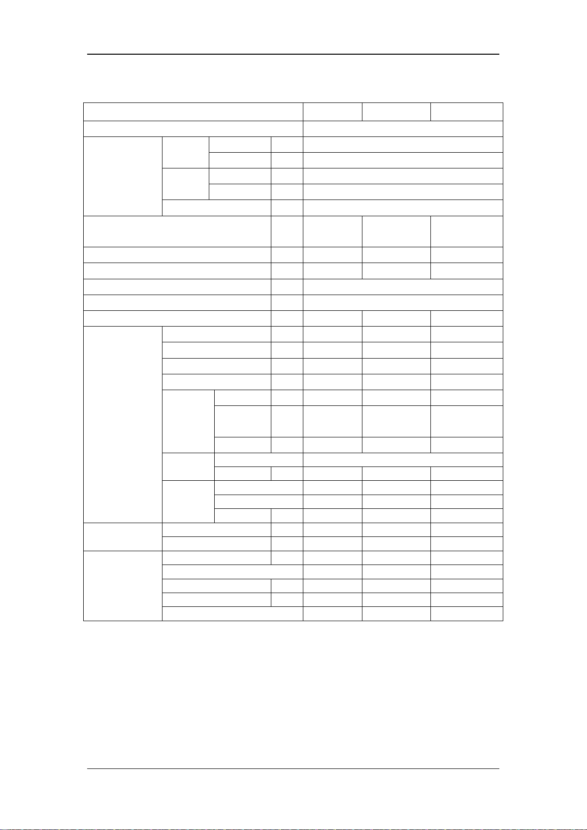
3.3 Hydronic box
Type
Heating & Cooling
Leaving water
temperature range
Space
heating
Low
°C
25~55, default 35
High
°C
35~60, default 45
Space
cooling
Low
°C
7~25, default 7
High
°C
18~25, default 18
Sanitary hot water
°C
40~60, default 45
Power supply
V/Ph/
Hz
220-240/1/50
220-240/1/50
380-415/3/50
MOP A 19
19
13.0
MCA A 17
17
10.0
Dimension (W×H×D)
mm
400×865×427
Packing (W×H×D)
mm
495×1040×495
Net/gross weight
kg
43/51
54/62
54/62
Water circuit
Piping connections Dia.
mm
DN25
DN25
DN25
Safety valve
kPa
300
300
300
Total water volume
L
4.7 5 5
Drainage pipe
mm
Ф16
Ф16
Ф16
Expansion
tank
Volume L 3 3 3
Max. water
pressure
kPa
800
800
800
Pre pressure
kPa
150
150
150
Water side
exchanger
Type
Plate type heat exchanger
Volume L 0.7 1 1
Water
pump
Brand
Wilo
Wilo
Wilo
Model
RS15/6 RKC
RS25/7.5 RKC
RS25/7.5 RKC
Pump head
m 6 7.5
7.5
Refrigerant circuit
Liqiud side Dia.
mm
Φ9.5
Φ9.5
Φ9.5
Gas side Dia.
mm
Φ15.9
Φ15.9
Φ15.9
Mounted Back-up
E-heater
Size
kW
3.0 3 4.5
Step 2 2
2
MOP A 17
17
12.0
MCA A 15
15
9.0
Power supply
220-240/1/50
220-240/1/50
380-415/3/50
Indoor Split type (Bibloc)
Service Manual
Aerotherm V17
4 ~ 8KW
10 ~ 16KW 10 ~ 16KW (TRIF.)
MOP: Maximum Overcurrent Protection MCA: Minimum Circuit Amps
Nominal capacity is based on the following conditions
1. Condition 1: Heating mode air inlet at 7°C and water outlet at 35°C with ΔT at 5°C, Cooling mode air inlet at 35°C
and water outlet at 18°C with ΔT at 5°C
2. Condition 2: Heating mode air inlet at 7°C and water outlet at 45°C with ΔT at 5°C, Cooling mode air inlet at 35°C
and water outlet at 7°C with ΔT at 5°C
3. Noise level is test at 1m in open field fan side, in heating mode with air inlet at 7°C and water outlet at 35°C with Δ
T at 5°C
4. The above data test reference standard EN14511
14

Service Manual
Aerotherm V17
4. Operation range
Heating mode Cooling mode
T1: Leaving water temperature (℃) T4 : Ambient temperature(℃)
■ No heat pump operation, backup E-heater or boiler only.
Domestic hot water mode
T4
43
30
-2
-
20
5 12
T1: Leaving water temperature (℃) T4 : Ambient temperature(℃)
5040 60
■ No heat pump operation, backup E-heater or boiler only.
T1
15
Model
Heating dB(A)
Cooling dB(A)
62
62
62
62
64
64
65
65
66
66
69
69
71
71
66
66
69
69
71
71
Micro
phone
Service Manual
Aerotherm V17
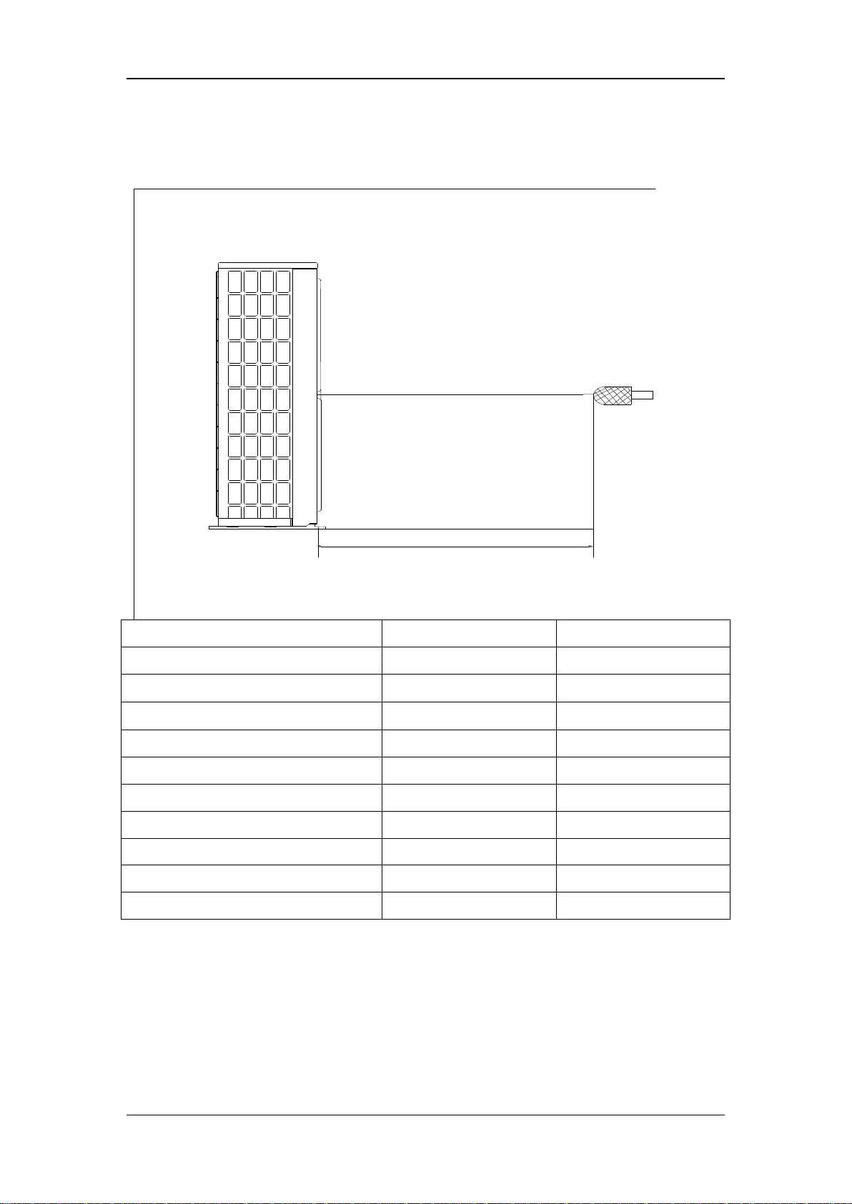
5. Sound pressure levels
Outdoo
r Unit
1.4m
UE BIBLOC AEROTHERM V17 (4KW)
UE BIBLOC AEROTHERM V17 (6KW)
UE BIBLOC AEROTHERM V17 (8KW)
UE BIBLOC AEROTHERM V17 (10KW)
UE BIBLOC AEROTHERM V17 (12KW)
UE BIBLOC AEROTHERM V17 (14KW)
UE BIBLOC AEROTHERM V17 (16KW)
UE BIBLOC AEROTHERM V17 (12KW)
UE BIBLOC AEROTHERM V17 (14KW)
UE BIBLOC AEROTHERM V17 (16KW)
(TRIF.)
(TRIF.)
(TRIF.)
Note:
1.0m
It is tested 1 meter away from the machine in a semi-anechoic room (sound
pressure).
16
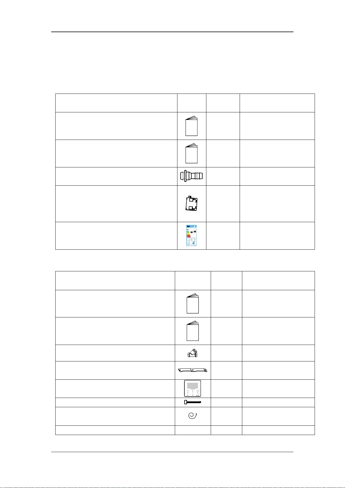
6. Accessories
6.1 Accessories for outdoor unit
NC-30
6.2 Accessories for hydronic box
Service Manual
Aerotherm V17
Name Shape Quantity Note
Outdoor unit installation &owner’s manual
Product technical manual
1
1 For Erp description
For outdoor unit
installation
Drainage pipe connector
1 For drainage
Only for 1 Phase 10~16
Magnet ring
1
kW, used on the signal
wire between outdoor
unit and hydronic box
Energy label
1 For hydronic box
Name Shape Quantity Note
Indoor unit installation & owner’s manual
User interface installation & owner’s
manual
Y-shape filter
Mounting bracket
User interface
M8 expansion screws
T5 temperature sensor for domestic hot
water tank
Copper nut - 1
17
1
For hydronic box
installation instruction
1 For operation instruction
1
1
For mounting hydronic
box
1
5
1
LWE
Tamb
30
35
45
50
55
60
HC
PI
COP
HC
HC
PI
COP
HC
PI
COP
HC
PI
COP
HC
-20/-
1.85
0.88
2.10
1.65
-15/-
2.10
0.82
2.57
2.08
0.89
2.35
2.08
0.94
2.22
2.12
1.05
2.01
-7/-8
3.51
1.04
3.39
3.32
1.08
3.08
3.16
1.14
2.76
2.98
1.24
2.41
2.83
1.18
2.39
2.66
1.13
2.35
2/1
4.38
1.04
4.21
4.08
1.07
3.81
3.82
1.11
3.45
3.50
1.16
3.02
2.82
0.96
2.95
2.20
0.78
2.83
1.60
0.60
2.66
7/6
5.87
1.09
5.38
5.28
1.09
4.86
4.71
1.08
4.37
4.12
1.07
3.85
3.32
1.00
3.33
2.43
0.89
2.73
1.59
0.74
2.16
15/12
4.86
0.83
5.87
4.12
0.76
5.42
3.52
0.77
4.56
2.71
0.73
3.71
2.19
0.67
3.26
1.95
0.72
2.72
1.43
0.61
2.35
20/15
4.72
0.79
5.99
4.22
0.78
5.39
3.78
0.75
5.03
3.22
0.71
4.55
2.64
0.67
3.94
2.05
0.63
3.28
1.42
0.55
2.58
25/18
4.81
0.79
6.08
4.38
0.82
5.31
4.03
0.74
5.42
3.55
0.65
5.50
2.91
0.61
4.79
2.19
0.54
4.02
1.45
0.44
3.30
35/24
4.71
0.76
6.21
4.45
0.83
5.37
4.26
0.72
5.95
4.02
0.62
6.48
3.24
0.59
5.52
2.45
0.55
4.49
Service Manual
Aerotherm V17
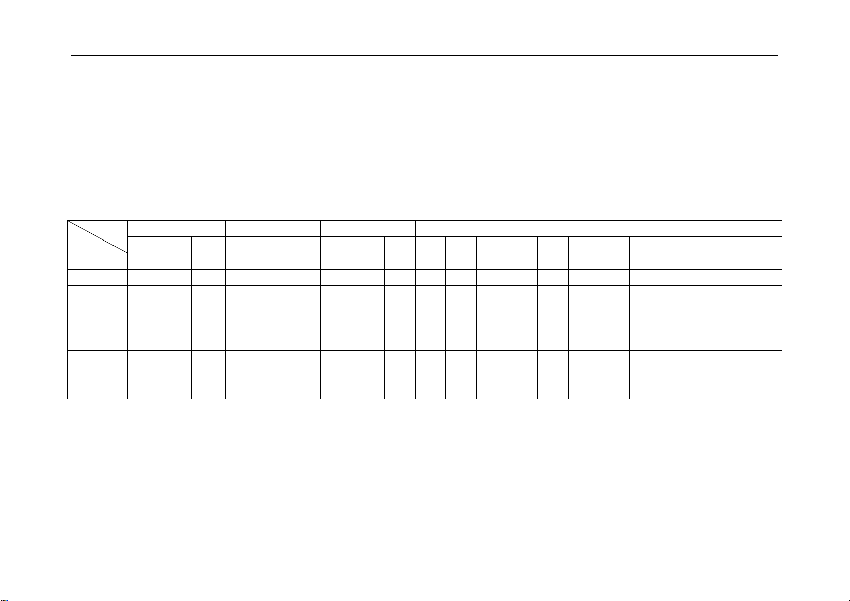
7. Performance data
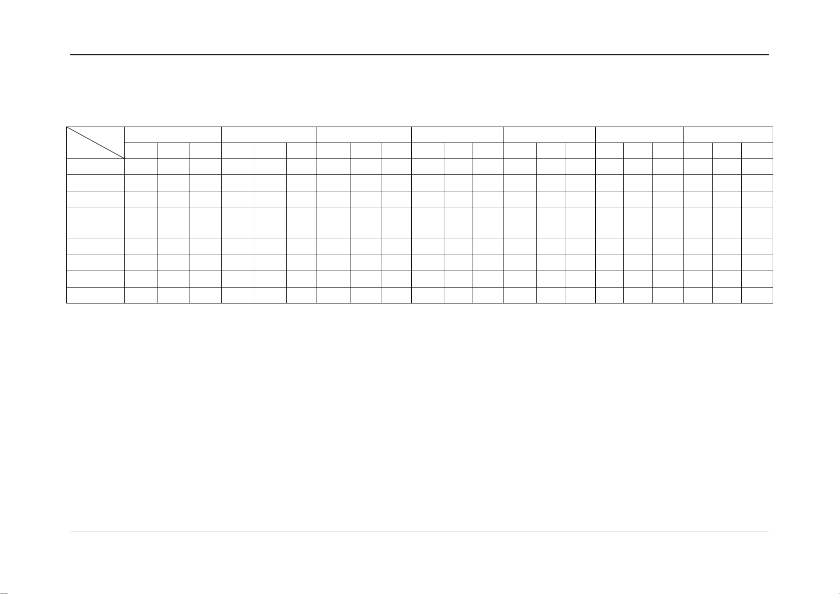
7.1 Heating capacity for 220-240/1/50 products
Model:
BIBLOC AEROTHERM V17 (4KW)
Integrated value capacity table
40
PI COP HC PI COP
0.88 1.88 1.51 0.88 1.72
PI COP
Integrated value takes into consideration the capacity drop during frosting and defrosting periods. The capacity is tested in free frequency situation.
Remark:
LWE: Leaving water temperature (℃) Tamb : Ambient temperature(℃)
HC: Heating capacity (kW) PI : Power input (kW)
18
LWE
Tamb
30
35
40
45
50
55
60
HC
PI
COP
HC
PI
COP
HC
PI
COP
HC
PI
COP
HC
PI
COP
HC
PI
COP
HC
PI
COP
-20/-
2.61
1.31
1.99
2.32
1.31
1.77
2.15
1.34
1.61
-15/-
3.08
1.27
2.43
3.06
3.02
1.59
1.90
-7/-8
5.24
1.62
3.23
4.95
4.38
1.92
2.28
4.21
1.86
2.26
3.94
1.78
2.21
2/1
6.55
1.64
4.00
6.10
5.20
1.81
2.87
4.28
1.53
2.79
3.26
1.21
2.69
2.25
7/6
8.81
1.72
5.11
7.93
6.17
1.68
3.67
4.95
1.57
3.16
3.59
1.38
2.60
2.28
15/12
7.27
1.30
5.60
6.19
4.03
1.15
3.51
3.25
1.05
3.10
2.28
0.88
2.60
1.45
20/15
7.08
1.24
5.70
6.32
4.80
1.10
4.35
3.96
1.06
3.75
2.98
0.96
3.11
2.01
25/18
7.20
1.24
5.80
6.57
1.30
5.07
6.02
1.17
5.15
5.31
1.02
5.21
4.35
0.96
4.55
3.27
0.86
3.82
2.12
0.68
3.11
35/24
7.09
1.20
5.91
6.72
1.31
5.12
6.42
1.13
5.68
5.99
0.97
6.20
4.88
0.92
5.28
3.62
0.85
4.26
Service Manual
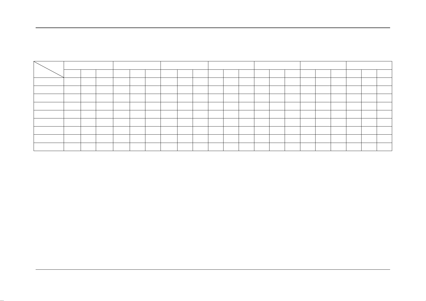
Aerotherm V17
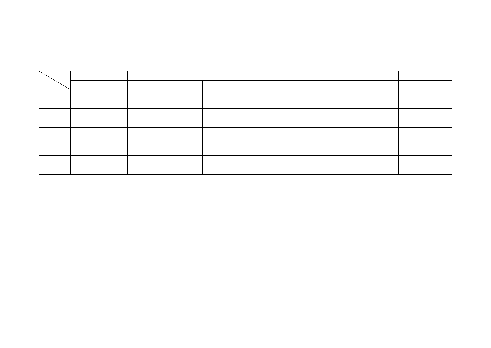
Model:
BIBLOC AEROTHERM V17 (6KW)
Integrated value capacity table
1.36 2.25 3.05 1.46 2.09
1.70 2.91 4.71 1.80 2.62
1.69 3.62 5.71 1.74 3.28
1.71 4.63 7.05 1.69 4.17
1.20 5.15 5.25 1.20 4.36
1.23 5.12 5.65 1.18 4.77
0.89 2.52
1.11 2.05
0.67 2.16
0.82 2.45
Integrated value takes into consideration the capacity drop during frosting and defrosting periods. The capacity is tested in free frequency situation.
Remark:
LWE: Leaving water temperature (℃) Tamb : Ambient temperature(℃)
HC: Heating capacity (kW) PI : Power input (kW)
19

LWE
Tamb
30
35
40
45
50
55
60
HC
PI
COP
HC
PI
COP
HC
PI
COP
HC
PI
COP
HC
PI
COP
HC
PI
COP
HC
PI
COP
-20/-
3.12
1.73
1.80
3.00
2.07
1.45
2.25
1.73
1.30
-15/-
3.25
1.62
2.01
3.07
3.81
2.53
1.51
-7/-8
6.22
2.32
2.68
6.22
5.64
2.93
1.92
5.05
3.01
1.68
4.25
2.93
1.45
2/1
9.00
2.20
4.09
8.40
6.81
2.76
2.47
5.82
2.79
2.09
4.68
2.82
1.66
3.43
7/6
12.66
2.58
4.90
10.75
7.55
2.40
3.14
6.25
2.36
2.65
5.15
2.23
2.31
4.26
15/12
11.30
1.97
5.75
9.72
6.79
1.81
3.74
5.44
1.98
2.75
4.14
1.70
2.44
2.95
20/15
12.98
2.00
6.48
10.81
7.41
1.71
4.33
6.12
1.72
3.55
4.87
1.62
3.01
3.99
25/18
14.69
2.05
7.17
11.94
1.87
6.39
9.72
1.72
5.64
7.98
1.62
4.92
6.76
1.60
4.23
6.03
1.69
3.56
5.44
1.86
2.92
35/24
15.21
1.76
8.65
13.10
1.70
7.72
10.66
1.53
6.98
9.12
1.46
6.26
7.68
1.50
5.12
6.53
1.54
4.23
Service Manual
Aerotherm V17
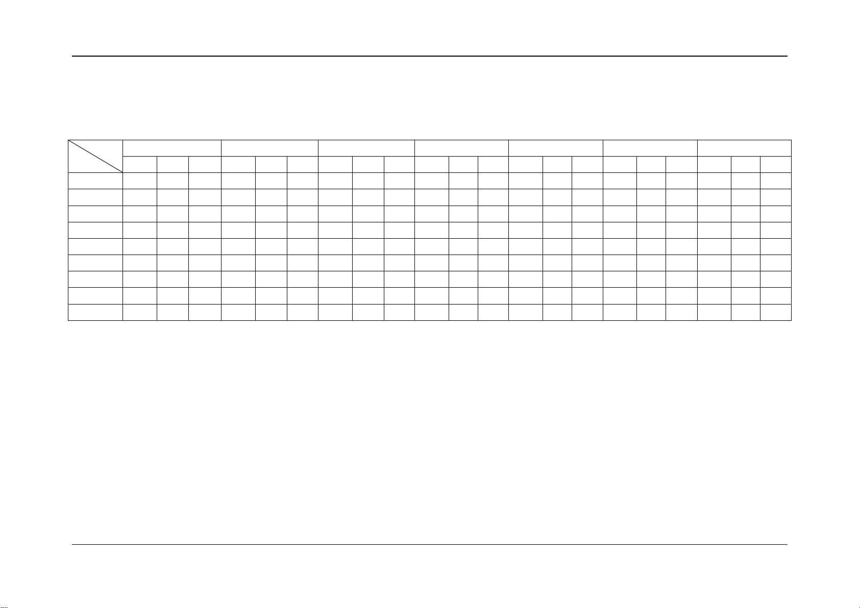
Model:
BIBLOC AEROTHERM V17 (8KW)
Integrated value capacity table
1.97 1.56 3.45 2.25 1.53
2.57 2.42 6.04 2.79 2.17
2.41 3.48 7.68 2.57 2.99
2.59 4.15 9.05 2.51 3.60
1.92 5.07 8.23 1.97 4.19
1.89 5.73 8.92 1.80 4.95
2.47 1.39
2.24 1.90
1.47 2.00
1.66 2.41
Integrated value takes into consideration the capacity drop during frosting and defrosting periods. The capacity is tested in free frequency situation.
Remark:
LWE: Leaving water temperature (℃) Tamb : Ambient temperature(℃)
HC: Heating capacity (kW) PI : Power input (kW)
20
LWE
Tamb
30
35
40
45
50
55
60
HC
PI
COP
HC
PI
COP
HC
PI
COP
HC
PI
COP
HC
PI
COP
HC
PI
COP
HC
PI
COP
-20/-
3.96
2.11
1.88
3.73
-15/-
5.24
2.17
2.41
4.99
4.24
2.47
1.72
-7/-8
8.04
2.73
2.94
8.25
7.39
3.47
2.13
7.13
3.26
2.19
6.02
3.34
1.80
2/1
9.31
2.73
3.41
8.98
9.09
3.51
2.59
8.17
3.40
2.40
7.67
3.49
2.20
3.87
7/6
11.60
2.74
4.24
11.31
12.13
3.51
3.46
10.57
3.25
3.25
8.06
2.87
2.81
5.09
15/12
12.12
2.04
5.95
10.75
9.26
2.25
4.12
8.75
2.48
3.53
7.98
2.71
2.94
4.62
20/15
11.79
1.54
7.68
10.32
1.57
6.58
8.54
1.49
5.73
8.09
1.68
4.81
7.57
1.88
4.03
7.04
2.09
3.37
6.13
2.08
2.95
25/18
11.93
1.42
8.43
10.55
1.46
7.25
8.99
1.39
6.47
8.54
1.58
5.42
8.34
1.79
4.67
7.84
1.98
3.96
7.21
2.10
3.44
35/24
12.28
1.31
9.39
10.77
1.40
7.72
9.36
1.33
7.02
8.88
1.49
5.95
8.49
1.70
4.98
7.94
1.93
4.11
Service Manual
Aerotherm V17
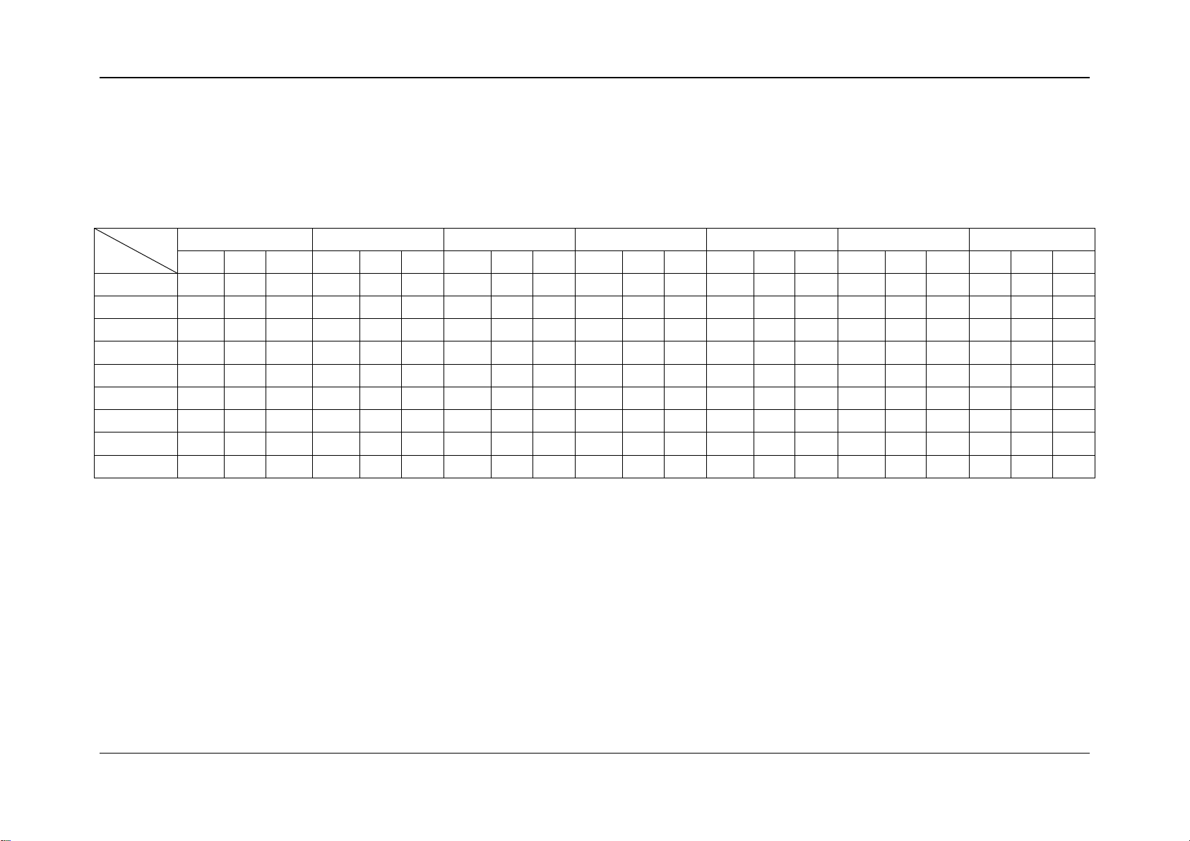
Model:
BIBLOC AEROTHERM V17 (10KW)
Integrated value capacity table
2.25 1.66 3.09 1.99 1.55
2.34 2.13 4.44 2.30 1.93
3.04 2.71 7.94 3.27 2.43
2.93 3.07 9.12 3.19 2.86
2.79 4.05 12.46 3.24 3.84
1.91 5.64 9.87 2.04 4.85
2.24 1.73
2.15 2.37
2.04 2.26
Integrated value takes into consideration the capacity drop during frosting and defrosting periods. The capacity is tested in free frequency situation.
Remark:
LWE: Leaving water temperature (℃) Tamb : Ambient temperature(℃)
HC: Heating capacity (kW) PI : Power input (kW)
21
LWE
Tamb
30
35
40
45
50
55
60
HC
PI
COP
HC
PI
COP
HC
PI
COP
HC
PI
COP
HC
PI
COP
HC
PI
COP
HC
PI
COP
-20/-
4.68
2.59
1.81
4.40
2.73
1.61
3.66
2.44
1.50
-15/-
6.19
2.67
2.32
5.90
5.01
3.02
1.66
-7/-8
9.51
3.35
2.84
9.75
8.73
4.24
2.06
8.42
3.99
2.11
7.12
4.12
1.73
2/1
11.00
3.34
3.29
10.61
10.74
4.31
2.49
9.65
4.18
2.31
9.07
4.28
2.12
4.57
7/6
13.71
3.35
4.09
13.37
14.33
4.29
3.34
12.49
3.98
3.14
9.53
3.52
2.71
6.01
15/12
14.32
2.49
5.74
12.70
10.95
2.76
3.97
10.34
3.04
3.40
9.43
3.32
2.84
5.46
20/15
13.94
1.88
7.41
12.20
9.56
2.06
4.64
8.95
2.30
3.89
8.32
2.55
3.26
7.24
25/18
14.10
1.73
8.14
12.47
1.78
6.99
10.62
1.70
6.24
10.09
1.93
5.23
9.86
2.19
4.51
9.27
2.43
3.82
8.52
2.57
3.32
35/24
14.51
1.60
9.06
12.73
1.71
7.45
11.06
1.63
6.78
10.50
1.83
5.74
10.03
2.09
4.81
9.38
2.37
3.96
Model:
Service Manual
Aerotherm V17
BIBLOC AEROTHERM V17 (12KW)
Integrated value capacity table
2.86 2.06 5.25 2.82 1.86
3.74 2.61 9.39 4.01 2.34
3.57 2.97 10.78 3.91 2.76
3.42 3.91 14.72 3.98 3.70
2.33 5.44 11.66 2.49 4.68
1.92 6.35 10.09 1.83 5.52
2.74 1.67
2.62 2.29
2.50 2.18
2.54 2.85
Integrated value takes into consideration the capacity drop during frosting and defrosting periods. The capacity is tested in free frequency situation.
Remark:
LWE: Leaving water temperature (℃) Tamb : Ambient temperature(℃)
HC: Heating capacity (kW) PI : Power input (kW)
22

LWE
Tamb
30
35
40
45
50
55
60
HC
PI
COP
HC
PI
COP
HC
PI
COP
HC
PI
COP
HC
PI
COP
HC
PI
COP
HC
PI
COP
-20/-
5.22
3.05
1.71
4.91
-15/-
6.91
3.14
2.20
6.58
5.59
3.56
1.57
-7/-8
10.60
3.96
2.68
10.88
9.74
5.02
1.94
9.40
4.72
1.99
7.94
4.84
1.64
2/1
12.27
3.95
3.11
11.84
11.98
5.08
2.36
10.77
4.92
2.19
10.12
5.06
2.00
5.10
7/6
15.29
3.95
3.87
14.91
15.98
5.06
3.16
13.94
4.69
2.97
10.63
4.15
2.56
6.71
15/12
15.98
2.94
5.43
14.17
12.21
3.25
3.76
11.53
3.58
3.22
10.51
3.92
2.68
6.09
20/15
15.54
2.22
7.00
13.60
2.27
6.00
11.26
2.16
5.22
10.66
2.43
4.38
9.98
2.72
3.67
9.28
3.01
3.08
8.07
3.00
2.69
25/18
15.73
2.05
7.69
13.91
2.10
6.61
11.85
2.01
5.90
11.26
2.28
4.94
11.00
2.58
4.26
10.34
2.86
3.61
9.50
3.03
3.14
35/24
16.19
1.89
8.56
14.20
2.02
7.04
12.33
1.92
6.41
11.71
2.16
5.43
11.19
2.46
4.54
10.47
2.79
3.75
Service Manual
Aerotherm V17
Model:
BIBLOC AEROTHERM V17 (14KW)
Integrated value capacity table
3.23 1.52 4.08 2.87 1.42
3.39 1.94 5.86 3.33 1.76
4.40 2.47 10.47 4.72 2.22
4.23 2.80 12.02 4.61 2.61
4.04 3.69 16.42 4.69 3.50
2.76 5.14 13.01 2.94 4.42
3.23 1.58
3.09 2.17
2.96 2.06
Integrated value takes into consideration the capacity drop during frosting and defrosting periods. The capacity is tested in free frequency situation.
Remark:
LWE: Leaving water temperature (℃) Tamb : Ambient temperature(℃)
HC: Heating capacity (kW) PI : Power input (kW)
23
LWE
Tamb
30
35
40
45
50
55
60
HC
PI
COP
HC
PI
COP
HC
PI
COP
HC
PI
COP
HC
PI
COP
HC
PI
COP
HC
PI
COP
-20/-
5.75
3.40
1.69
5.42
-15/-
7.62
3.52
2.17
7.26
6.17
3.97
1.55
-7/-8
11.70
4.42
2.65
12.00
10.74
5.59
1.92
10.37
5.27
1.97
8.76
5.41
1.62
2/1
13.53
4.41
3.07
13.06
13.22
5.67
2.33
11.88
5.51
2.16
11.16
5.63
1.98
5.63
7/6
16.87
4.42
3.82
16.45
17.64
5.65
3.12
15.38
5.24
2.93
11.73
4.63
2.53
7.40
15/12
17.63
3.29
5.36
15.63
13.47
3.63
3.71
12.72
4.00
3.18
11.60
4.37
2.65
6.72
20/15
17.15
2.48
6.92
15.01
2.53
5.93
12.42
2.41
5.16
11.76
2.72
4.33
11.01
3.04
3.63
10.24
3.37
3.04
8.91
3.35
2.66
25/18
17.35
2.28
7.60
15.35
2.35
6.53
13.07
2.24
5.83
12.42
2.55
4.88
12.14
2.88
4.21
11.41
3.20
3.57
10.48
3.38
3.10
35/24
17.86
2.11
8.46
15.67
2.25
6.96
13.61
2.15
6.33
12.92
2.41
5.36
12.35
2.75
4.49
11.55
3.12
3.70
Model:
Service Manual
Aerotherm V17
BIBLOC AEROTHERM V17 (16KW)
Integrated value capacity table
3.61 1.50 4.50 3.21 1.40
3.78 1.92 6.46 3.70 1.74
4.92 2.44 11.55 5.27 2.19
4.72 2.77 13.27 5.15 2.58
4.50 3.65 18.12 5.23 3.46
3.08 5.08 14.36 3.29 4.37
3.61 1.56
3.45 2.14
3.29 2.04
Integrated value takes into consideration the capacity drop during frosting and defrosting periods. The capacity is tested in free frequency situation.
Remark:
LWE: Leaving water temperature (℃) Tamb : Ambient temperature(℃)
HC: Heating capacity (kW) PI : Power input (kW)
24
LWE
Tamb
30
35
40
45
50
55
60
HC
PI
COP
HC
HC
PI
COP
HC
PI
COP
HC
PI
COP
HC
-20/-
4.93
2.72
1.81
4.64
-15/-
6.71
2.78
2.41
6.19
5.27
3.03
1.74
-7/-8
10.29
3.41
3.02
9.87
9.14
4.25
2.15
7.92
4.30
1.84
6.57
4.35
1.51
2/1
12.20
3.47
3.52
11.90
11.67
4.34
2.69
11.09
4.30
2.58
10.45
4.28
2.44
4.76
7/6
13.27
3.50
3.79
14.09
15.76
4.57
3.45
13.26
4.14
3.20
10.49
3.59
2.92
6.19
15/12
14.28
2.28
6.26
13.43
2.46
5.45
12.62
2.66
4.74
11.80
2.87
4.11
11.14
3.09
3.60
10.39
3.40
3.06
5.67
2.51
2.26
20/15
14.04
1.92
7.33
12.82
1.99
6.44
11.64
2.09
5.57
10.51
2.19
4.79
9.87
2.37
4.17
9.19
2.62
3.51
7.41
2.58
2.87
25/18
14.06
1.77
7.94
13.01
1.85
7.05
12.05
1.95
6.19
11.12
2.06
5.40
10.70
2.24
4.78
10.22
2.48
4.12
8.64
2.59
3.34
35/24
14.37
1.61
8.95
13.38
1.70
7.89
12.46
1.81
6.87
11.55
1.95
5.93
10.99
2.13
5.17
10.35
2.40
4.31
Service Manual
Aerotherm V17
7.2 Heating capacity for 380-415/3/50 products
Model:
BIBLOC AEROTHERM V17 (12KW) (TRIF.)
Integrated value capacity table
PI COP HC PI COP
2.70 1.72 4.50 2.69 1.67
2.85 2.17 5.77 2.94 1.96
3.64 2.71 9.53 3.87 2.46
3.67 3.24 11.81 3.96 2.98
3.85 3.66 15.08 4.26 3.54
PI COP
2.75 1.73
2.63 2.35
Integrated value takes into consideration the capacity drop during frosting and defrosting periods. The capacity is tested in free frequency situation.
Remark:
LWE: Leaving water temperature (℃) Tamb : Ambient temperature(℃)
HC: Heating capacity (kW) PI : Power input (kW)
25
LWE
Tamb
30
35
40
45
50
55
60
HC
PI
COP
HC
PI
COP
HC
PI
COP
HC
PI
COP
HC
PI
COP
HC
PI
COP
HC
PI
COP
-20/-
5.68
3.25
1.75
5.34
3.24
1.65
5.17
3.21
1.61
-15/-
7.72
3.31
2.33
7.13
6.06
3.63
1.67
-7/-8
11.84
4.07
2.91
11.36
10.51
5.08
2.07
9.11
5.12
1.78
7.56
5.18
1.46
2/1
14.04
4.14
3.39
13.70
13.43
5.19
2.59
12.76
5.12
2.49
12.03
5.12
2.35
5.47
7/6
15.27
4.17
3.66
16.21
18.14
5.45
3.33
15.26
4.95
3.08
12.08
4.28
2.82
7.13
15/12
16.44
2.72
6.04
15.45
13.58
3.43
3.96
12.82
3.69
3.47
11.96
4.05
2.95
6.53
20/15
16.16
2.29
7.07
14.75
12.10
2.62
4.62
11.36
2.83
4.02
10.57
3.13
3.38
8.52
25/18
16.18
2.11
7.66
14.97
2.20
6.80
13.86
2.32
5.97
12.80
2.46
5.21
12.31
2.67
4.61
11.76
2.96
3.97
9.94
3.09
3.22
35/24
16.54
1.92
8.63
15.40
2.02
7.61
14.34
2.16
6.63
13.29
2.32
5.72
12.65
2.54
4.98
11.91
2.86
4.16
Model:
Service Manual
Aerotherm V17
BIBLOC AEROTHERM V17 (14KW) (TRIF.)
Integrated value capacity table
3.41 2.09 6.64 3.51 1.89
4.35 2.61 10.96 4.62 2.37
4.39 3.12 13.59 4.74 2.87
4.59 3.53 17.35 5.09 3.41
2.94 5.26 14.52 3.17 4.58
2.38 6.21 13.40 2.50 5.37
3.30 1.66
3.14 2.27
3.00 2.18
3.08 2.77
Integrated value takes into consideration the capacity drop during frosting and defrosting periods. The capacity is tested in free frequency situation.
Remark:
LWE: Leaving water temperature (℃) Tamb : Ambient temperature(℃)
HC: Heating capacity (kW) PI : Power input (kW)
26
LWE
Tamb
30
35
40
45
50
55
60
HC
PI
COP
HC
PI
COP
HC
PI
COP
HC
PI
COP
HC
PI
COP
HC
PI
COP
HC
PI
COP
-20/-
6.07
3.55
1.71
5.71
3.52
1.62
5.53
3.21
1.58
-15/-
8.25
3.62
2.28
7.62
6.48
3.95
1.64
-7/-8
12.66
4.44
2.85
12.15
11.24
5.55
2.03
9.74
5.60
1.74
8.09
5.67
1.43
2/1
15.01
4.52
3.32
14.64
14.36
5.65
2.54
13.64
5.59
2.44
12.86
5.59
2.30
5.85
7/6
16.32
4.56
3.58
17.33
19.39
5.94
3.26
16.31
5.40
3.02
12.91
4.68
2.76
7.62
15/12
17.57
2.97
5.91
16.52
14.52
3.74
3.88
13.70
4.03
3.40
12.78
4.42
2.89
6.98
20/15
17.27
2.50
6.92
15.77
12.93
2.86
4.52
12.14
3.08
3.94
11.30
3.41
3.31
9.11
25/18
17.30
2.31
7.50
16.00
2.40
6.66
14.82
2.53
5.85
13.68
2.68
5.10
13.16
2.92
4.51
12.57
3.23
3.89
10.63
3.37
3.15
35/24
17.68
2.09
8.45
16.46
2.21
7.45
15.33
2.36
6.49
14.21
2.54
5.60
13.52
2.77
4.88
12.73
3.13
4.07
Service Manual
Aerotherm V17
Model:
BIBLOC AEROTHERM V17 (16KW) (TRIF.)
Integrated value capacity table
3.72 2.05 7.10 3.70 1.85
4.75 2.56 11.72 5.05 2.32
4.78 3.06 14.53 5.17 2.81
5.00 3.46 18.55 5.55 3.34
3.21 5.15 15.52 3.46 4.48
2.59 6.08 14.32 2.72 5.26
3.60 1.63
3.43 2.22
3.28 2.13
3.36 2.71
Integrated value takes into consideration the capacity drop during frosting and defrosting periods. The capacity is tested in free frequency situation.
Remark:
LWE: Leaving water temperature (℃) Tamb : Ambient temperature(℃)
HC: Heating capacity (kW) PI : Power input (kW)
27
Service Manual
Aerotherm V17
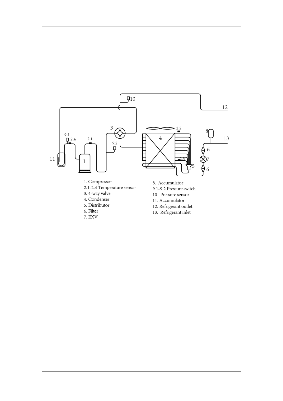
8. System diagram
8.1 System diagram for outdoor unit
28
Service Manual
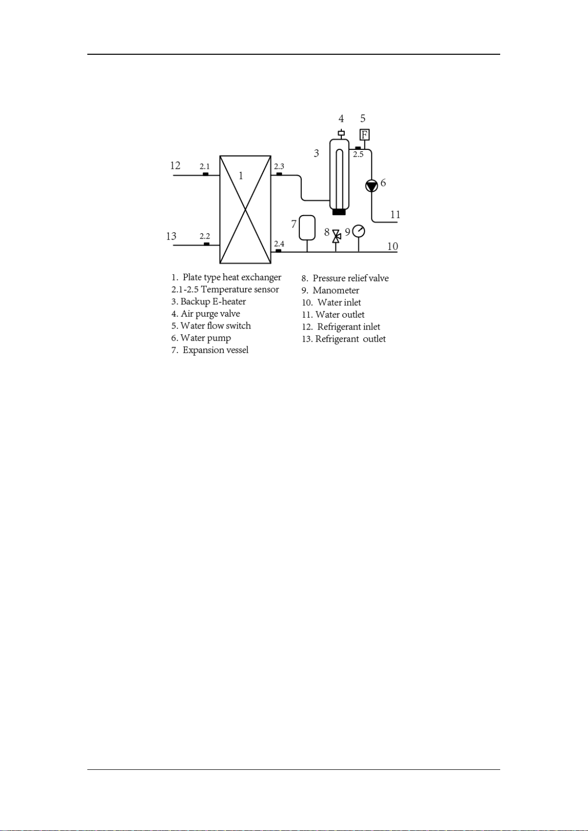
Aerotherm V17
8.2 System diagram for hydronic box
29
 Loading...