

MUND CLIMA MH-10-V5 Service Manual
HU10530 to HU10531
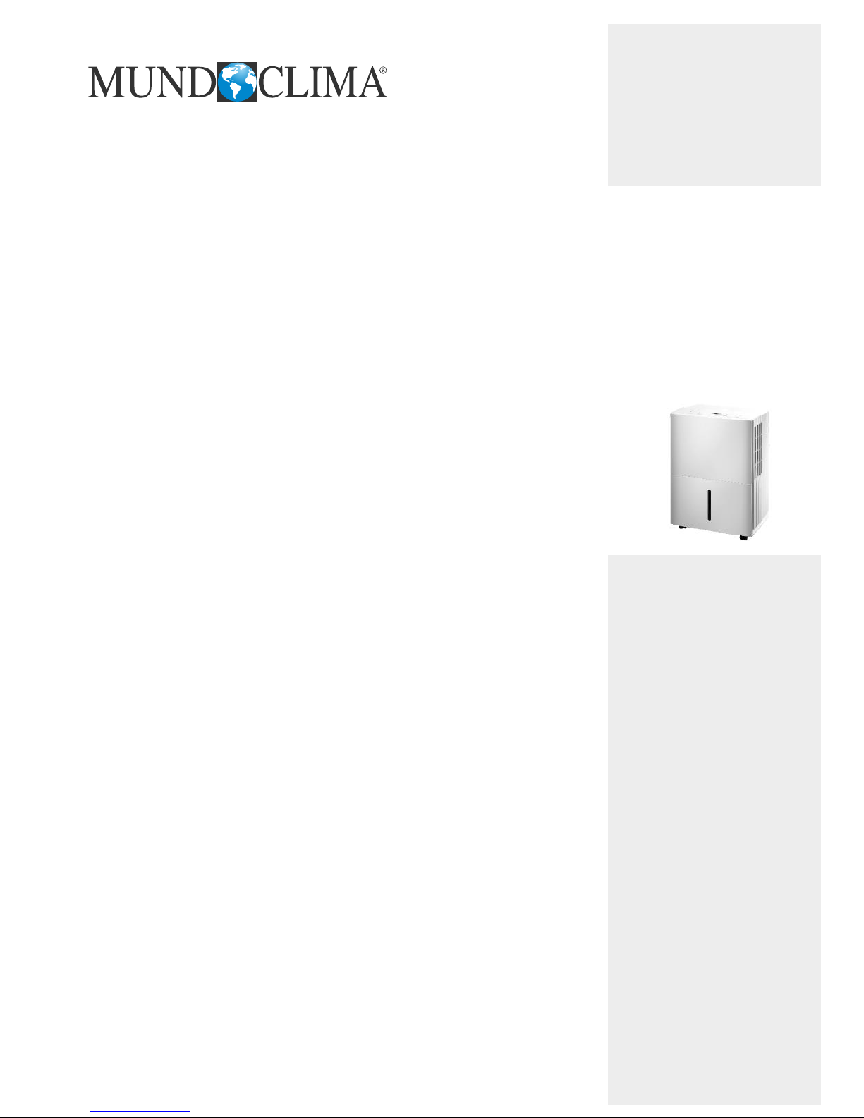
DESHUMIDIFIER MH-V5
Service manual
English
MH-10-V5
MH-20-V5

Service Manual
Table of Contents
Part
Ⅰ
: Technical Information
............................................................ 3
1.Summary
...................................................................................................... 3
2.Specications
........................................................................................... 4
3.Outline Dimension Diagram
..............................................................
6
4.Refrigerant System Diagram
............................................................7
5.Electrical Part
............................................................................................8
5.1 Wiring Diagram
...........................................................................................8
5.2 PCB Printed Diagram
..................................................................................9
6.Function and Control
.......................................................................... 11
6.1 Control Panel Instruction
........................................................................... 11
6.2 Introduction of Basic Mode Function
......................................................... 12
Part
Ⅱ
: Maintenance
............................................................................ 14
7.Notes Maintenance
.............................................................................. 14
8.Maintenance
............................................................................................. 15
8.1 Error Code
................................................................................................. 15
8.2 Malfunction Detection Flowchart
............................................................... 16
8.3 Maintenance Method for Common Malfunction
........................................ 18
9.Exploded View and Parts List
........................................................ 20
10.Removal Procedure
........................................................................... 23
Appendix:
...................................................................................................... 30
Appendix 1: Reference Sheet of Celsius and Fahrenheit
............................... 30
Appendix 2: Resistance T
able of Temperature Sensor
................................... 31
Appendix 3: Resistance Value
Table of Humidity Sensor
............................... 36
2
1.Summary
Part
Ⅰ
: Technical Information
Models
MH-10-V5
MH-20-V5
Service Manual
3
The above data is subject to change without notice; please refer to the nameplate of the unit.
Model
Product Code CK051024000
Power Supply
Rated Voltage V~ 220-240
Rated Frequency Hz 50
Phases 1
Rated Dehumidifying V
olume L/h 0.17
Power Input W 220
Power Current A 1.20
Set Humidity Range % 35~80
Air Flow Volume(H/M/L) m
3
/h 150/120/100
Fan Motor Speed (H/M/L) r/min 930/800/650
Output of Fan Motor W 6
Fan Motor Capacitor μF 1.0
Fan T
ype Centrifugal
Diameter Length(DXL) mm Φ180X76.5
Throttling Method Capillary
Fuse A 3.15
Sound Pressure Level (H/M/L) dB (A) 43/41/39
Sound Power Level ((H/M/L) dB (A) 53/51/49
Climate Type T1
Isolation I
Moisture Protection IPX0
Permissible Excessive Operating Pressure for the
Discharge Side
MPa 1.7
Permissible Excessive Operating Pressure for the
Suction Side
MPa 0.6
Dimension (WXHXD) mm 343X525X262
Dimension of Carton Box (LXWXH) mm 391X310X569
Dimension of Package (LXWXH) mm 394X313X584
Application Area m
2
14
Net Weight kg 13
Gross W
eight kg 14.5
Refrigerant R134a
Refrigerant Charge kg 0.08
Bucket Capacity L 4.0/4.6
Control Type Electronic
Evaporator
Form Aluminum Fin-copper Tube
Pipe Diameter mm Φ7
Row-n Gap mm 1-1.3
Coil Length (LXDXW) mm 235X12.7X190.5
Condenser
Form Aluminum Fin-copper Tube
Pipe Diameter mm Φ7
Rows-n Gap mm 1-1.4
Coil Length (LXDXW) mm 235X12.7X190.5
Compressor
Compressor Manufacturer/Trademark
Shanghai Hitachi Electrical
Appliances Co.,Ltd/HIGHLY
Model BSA418CV-R1AUA
Type Rotary
Power Input W 213
Overload Protector
URP-191-78
L.R.A. A 3.4
W
orking Current A 1.1
MH-10-V5
2.Specications
Service Manual
4
The above data is subject to change without notice; please refer to the nameplate of the unit.
Model
Product Code CK051023800
Power Supply
Rated Voltage V~ 220-240
Rated Frequency Hz 50
Phases 1
Rated Dehumidifying V
olume L/h 0.41
Power Input W 300
Power Current A 1.5
Set Humidity Range % 35~80
Air Flow Volume(H/M/L) m
3
/h 180/160/140
Fan Motor Speed (H/M/L) r/min 950/860/740
Output of Fan Motor W 7
Fan Motor RLA A 0.13
Fan Motor Capacitor μF 1
Fan T
ype Centrifugal
Diameter Length(DXL) mm Φ180X76.5
Throttling Method Capillary
Fuse A 3.15
Sound Pressure Level (H/M/L) dB (A) 45/43/41
Sound Power Level ((H/M/L) dB (A) 55/53/51
Climate Type T1
Isolation I
Moisture Protection IPX0
Permissible Excessive Operating Pressure for the
Discharge Side
MPa 1.7
Permissible Excessive Operating Pressure for the
Suction Side
MPa 0.6
Dimension (WXHXD) mm 343X525X262
Dimension of Carton Box (LXWXH) mm 391X310X569
Dimension of Package (LXWXH) mm 394X313X584
Application Area m
2
28
Net W
eight kg 15.5
Gross W
eight kg 17
Refrigerant R134a
Refrigerant Charge kg 0.2
Bucket Capacity L 4.0/4.6
Control Type Electronic
Evaporator
Form Aluminum Fin-copper Tube
Pipe Diameter mm Φ7
Row-n Gap mm 1-1.3
Coil Length (LXDXW) mm 235X12.7X190.5
Condenser
Form Aluminum Fin-copper Tube
Pipe Diameter mm Φ7
Rows-n Gap mm 2-1.4
Coil Length (LXDXW) mm 235X12.7X190.5
Compressor
Compressor Manufacturer/Trademark
RECHI PRECISION CO.,LTD/
RECHI
Model 39E073HR&F^YA
Type Rotary
Power Input
W 300
Overload Protector UP3-017
L.R.A. A 5.5
W
orking Current A 1.4
MH-20-V5
Service Manual
5

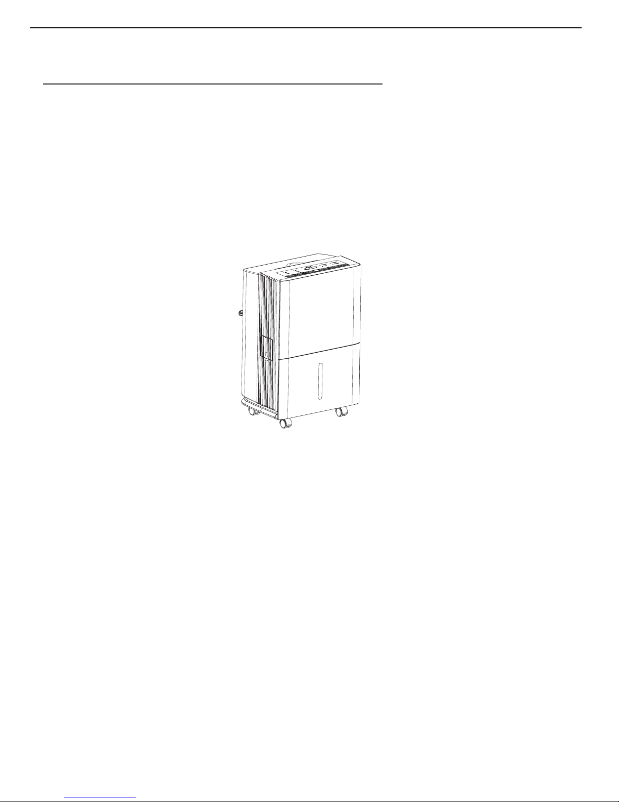
Service Manual
262
525
343
unit:mm
3.Outline Dimension Diagram
6
Service Manual
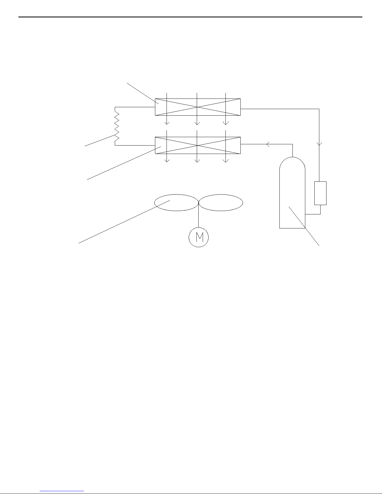
4.Refrigerant System Diagram
air in
evaporator
capillary
condenser
fan motor
air out
compressor
Dehumidifying principle of dehumidier:
When temperature is decreased to the temperature point of dew, water vapor in humid air will condensate. Dehumidier is
dehumidifying the air by using this principle.
During operation of the system, air will pass through evaporator and condenser in turn and then be discharged due to centrifugal
blade. When the air is passing through evaporator
, refrigerant will absorb the heat in air to let its temperature decrease to the
temperature point of dew, water vapor in air will condensate. Condensate water comes into water tank through water tray, or is
discharged directly through drainage hose. The saturated low-temperature air passed through the evaporator will absorb the heat
when owing along the condenser, and then become the dry air. Under normal condition, the nearby air will become warm during
operation of dehumidier.
7
Symbol Symbol Color Symbol Symbol Color Symbol Name
WH White GN Green COMP Compressor
YE Yellow BN Brown Grounding wire
RD Red BU Blue / /
YEGN Y
ellow/Green BK Black / /
VT Violet OG Orange / /
5.Electrical Part
5.1 Wiring Diagram
●Instruction
These circuit diagrames are subject to change without notice ,please refer to the one supplied with the unit.
PE
YEGN
CN4
SENSOR
ST
HUMIDITY
AC-L
YEGN
C1
C
RD
YEGN(GN)
BU(WH)
BN(BK)
CN1
AP2
CN1
CN3
AP1
L
N
COMP.
M
WA
TER LEVEL SWITCH
N1
PE
POWER
FAN
MOT
OR
PE
YEGN
PE
COMP
SA
COM
NO
BU
BN
CN2
K1
N
PE
TUBE
RT1
TUBE
TEMP.SENSOR
ELECTRIC
BOX
C2
YE
BU
BU
R
S
Service Manual
8
Service Manual
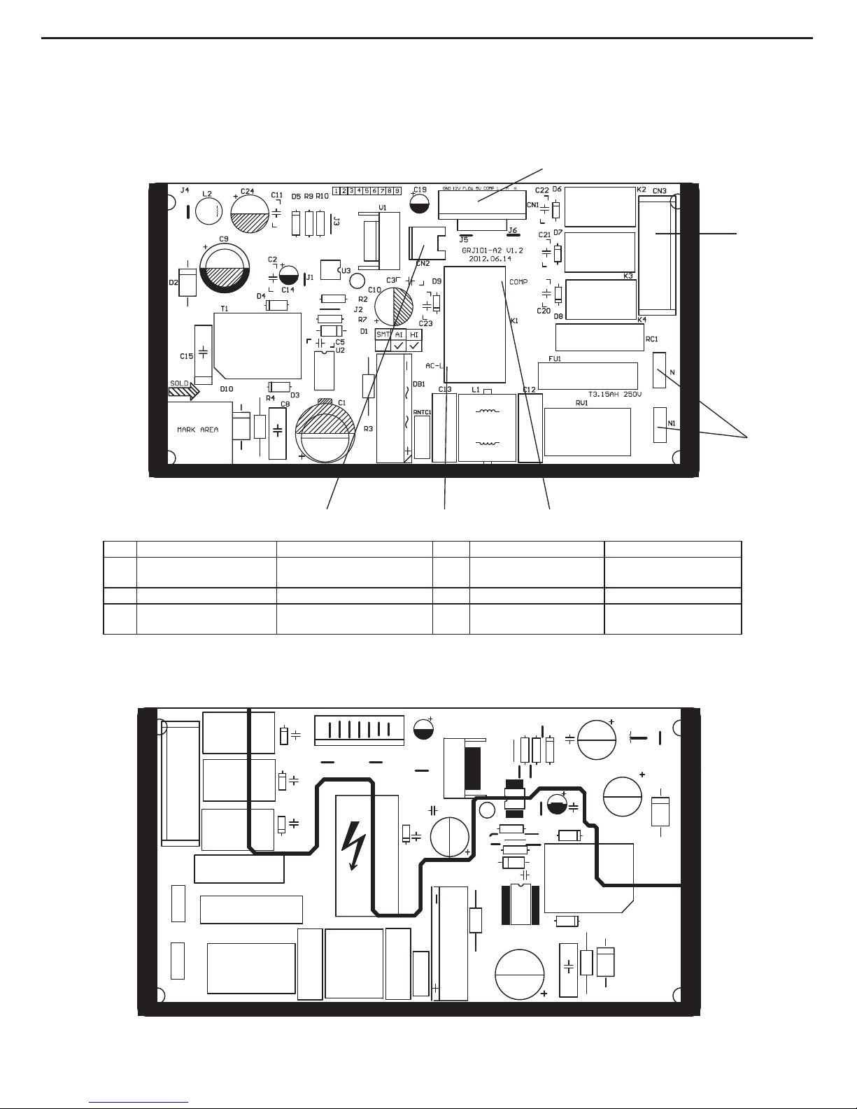
Silk Screen on Main Board
5.2 PCB Printed Diagram
● Top view
●
Bottom view
No. Name Description No. Name Description
1
Needle stand of board
connection wire
Connect to display board 4 Interface of neutral wire
Connect to neutral wire
of commercial wire
2 Needle stand of fan Connect to fan 5 Interface of compressor Connect to compressor
3 Interface of live wire
Connect to live wire of
commercial wire
6
Needle stand of water
blow protection switch
Connect to water blow
protection switch
6 3 5
4
1
2
9
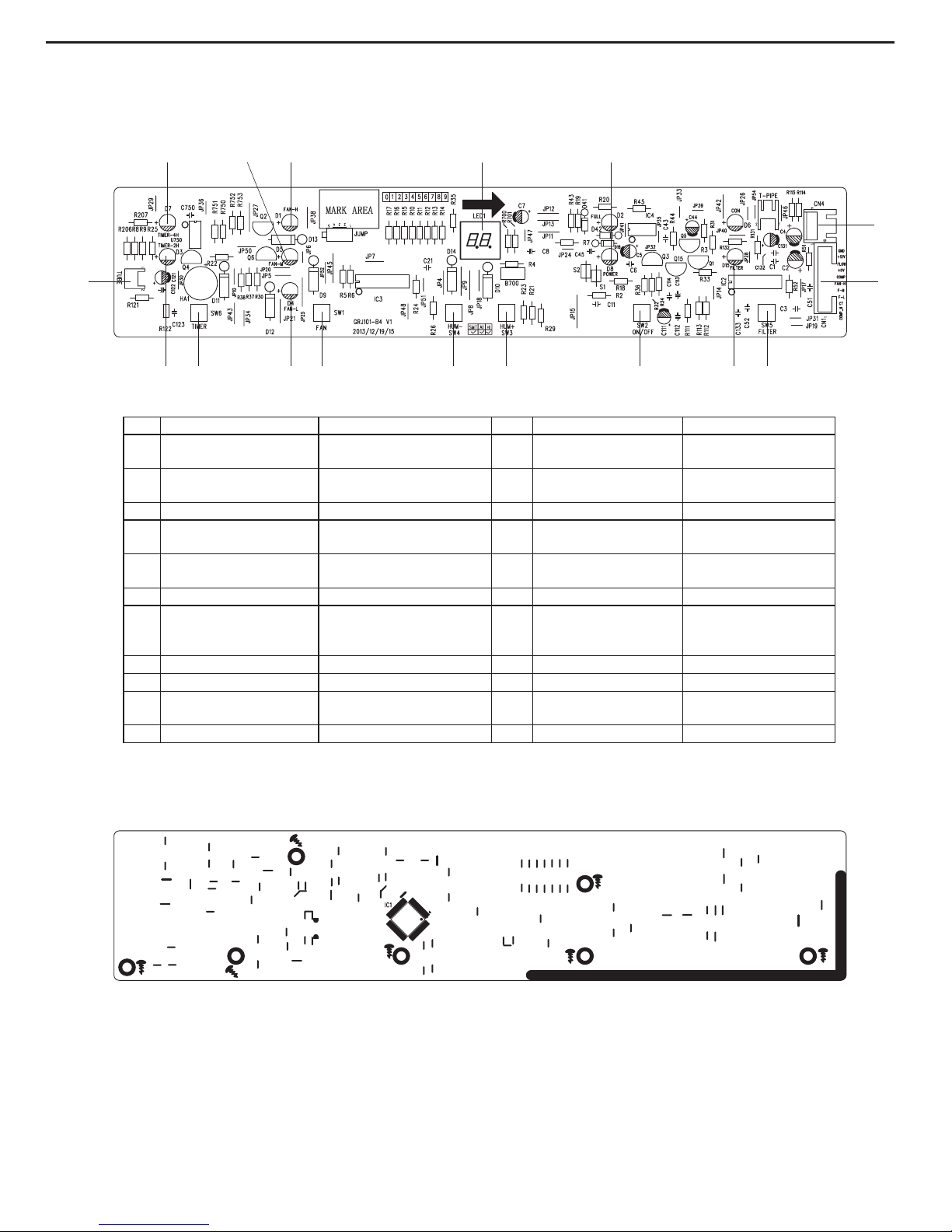
Silk Screen on Display Board
● Top view
●
Bottom view
No. Name Description No. Name Description
1
Needle stand of pipe
temperature sensor
Co
nnect to pipe temperature
sensor
12 Set humidity button
Increase set humidity
button
2 Timer 4H indicator Timer 4H indicator is on 13 Set humidity button
Decrease set humidity
button
3 Med fan step indicator Med fan step indicator is on 14 Fan speed button Preset fan speed button
4 High fan step indicator High fan step indicator is on 15 Low fan step indicator
Low fan step indicator is
on
5 Dual-8 digital display tube
Display ambient humidity or
preset temperature
16 Timer button Preset timer time button
6 Power supply indicator Power supply indicator is on 17 Timer 2H indicator Timer 2H indicator is on
7
Neddle stand of humidity
and ambient temperature
sensor
Connect to humidity and
ambient temperature sensor
/ / /
8 Connection wire of board Connect to mainboard / / /
9 Filter reset button Filter reset button / / /
10
Remind indicator of
cleaning lter
Remind indicator of cleaning
lter is on
/ / /
11 On/off button On/off button / / /
1
2
3 4 5 6
7
8
9101
112
1314151617
Service Manual
10
Service Manual
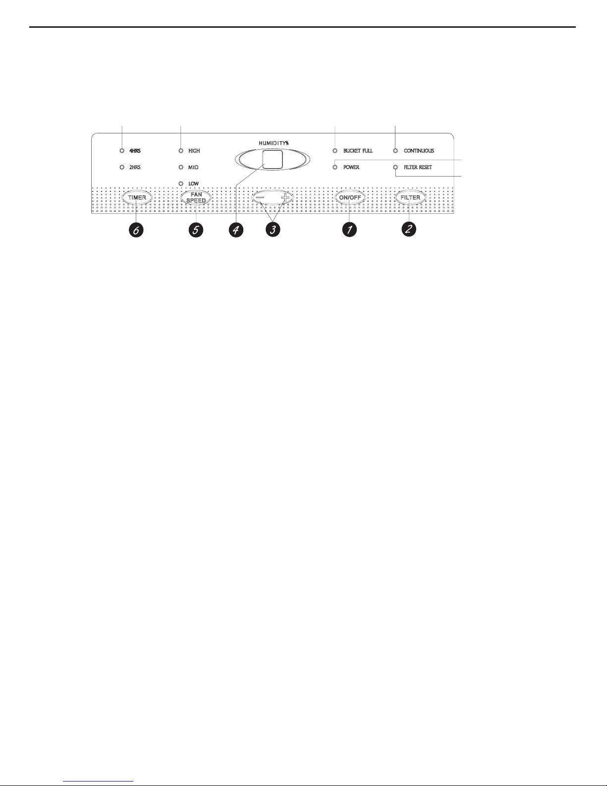
6.Function and Control
6.1 Control Panel Instruction
Clean the Filter
indicator light
Continuous operation on
indicator light
Bucket full light indicates
bucket needs to be emptied
or it is not in the proper place.
4 hour or 2 hour
delay on/off
indicator lights
High,Mid and Low fan
indicator lights
Power On
indicator light
1.ON/OFF Pad
Press to turn the dehumidier on or off.
2.FIL
TER Pad
After 250
hours of operation, the Clean the Filter indicator light will glow to remind you to clean the lter. Remove the lter and
clean it. Press to turn off the Clean the Filter light. See the Care and Cleaning section.
3.Humidity Set Control Pads
The humidity
level can be set within a range of 80% RH (Relative Humidity) to 35% RH (Relative Humidity) in 5% reduce or at
CO for continuous operation.
NOTE: If CO (Continuous) is selected, the dehumidier will operate continuously at its maximum dehumidication settings if
attached to a hose to drain or until the bucket is full.
For drier air, press the - pad and set to a lower percent value (%).
For damper air, press the + pad and set to a higher percent value (%).
When you first use the dehumidifier, set the humidity control to 45% or 50%. Allow at least 24 hours for the dehumidifier to
achieve the humidity level. If you still have damper air than desired, set the humidity level to a lower setting or select Continuous
for maximum dehumidication.
This unit has 3-min lag due to the device for protecting circuit .In order to prolong the compressors working life, the compressor
will not start until the unit has run for 3 minutes.
4.Display
Shows the set % humidity level while setting, then shows the actual (+/– 5% accuracy) room % humidity level.
5.F
AN SPEED Pad
Controls the fan speed. Press to select High or Mid or Low fan speed.
Se
t the fan control to High for maximum moisture removal. When the humidity has been reduced and quiet operation is preferred,
set the fan control to Mid or Low.
6.TIMER Pad
If unit
is turned on and running in timer mode for 2hr or 4hr,can turn off the unit. When unit stand by and running in timer mode
for 2hr or 4hr can turn on the unit.
Other Features
BUCKET FULL
Light
Glows when the bucket is ready to be emptied, or when the bucket is removed or not replaced in the proper position.
Alarm
If the
bucket is full or missing for more than three minutes, an alarm will sound for about 10 seconds to remind you to empty and
replace the bucket.
Auto Shut Off
The W
ater Level Control Switch shuts off the dehumidier when the bucket is full, or when the bucket is removed or not replaced
in the proper position.
Auto Defrost
Wh
en frost builds up on the evaporator coils, the compressor will cycle off and the fan will continue to run until the frost
disappears.
Power Outage
In
the case of a power outage or interruption, the unit will automatically re-start, in the settings last used, after the power is
restored.
11

6.2 Introduction of Basic Mode Function
1. Basic Function
1) Dry conditions and process
a. When HUMIDITYpreset≤HUMIDITY
amb.-5%, compressor and fan will run.
b. When HUMIDITYpreset≥HUMIDITYamb.+5%, compressor stop to run and fan will stop operation after 3min.
c. When DEHUMITYamb.-5%<HUMIDITYpreset<HUMIDITYamb.+5%, when compressor is operation, it will run with condition a; when
compressor stops, it will run with condition b. If under this condition when the unit is on, the compressor is off and fan will stop to run
after 3min delay.
2) Humidity Range
a. 5% is one step, it can be adjusted continuously from CO, 35%-80% (CO stands for dehumidify continuously).
b. Adjust preset temperature by “+” and “-”.
2. Protection Function
(1) Working temperature range
a.
Detect the unit after energized, when 2℃≤Tamb. ≤45℃, the unit is running normally; when Tamb. <2℃ or Tamb.> 45℃, the
compressor stops, and fan will run with the detected temperature humidity;
b. During operation, when Tamb. <2℃ or Tamb.> 45℃, the compressor stops, and fan will run with the detected temperature humidity;
when 2℃≤Tamb. ≤45℃, the compressor will be started up.
(2) Compressor Protection
a. After energization, under any situation and after compressor stops, it will restart 3min delay at least.
b. Under operation state except temperature sensor malfunction, on/off button, water-blow protection, after compressor starts up, it will
stop after it runs for 3min at least.
(3) Detection for temperature sensor malfunction (Temperature sensor malfunction is AD value≤5 or 250≤AD value)
a. When the unit is energized, it is detected that the ambient temperature sensor is open or short circuit for 30s, compressor and fan
stops, LED indicator is off, buttons are invalid, and nixie tube displays “F1”.
b. It is detected that the pipe temperature sensor is open or short circuit for 30s, compressor and fan stops, LED indicator is off, buttons
are invalid, and nixie tube displays “F2”.
c. When it detected that the humidity sensor is short-circuited for 30s successively, compressor and fan will stop operation. Meanwhile,
LED will be off, buttons are invalid and dual-8 nixie tube will display L1.
d. When theres multiple malfunctions, the error codes will be displayed in turn.
(4) Water blow protection (off switch)
a. The water blow protection will be occurred when the water level of water tank is exceeded. After water blow protection, compressor
stops and fan stops after 3mins. If water blow protection occurred for 3min, the buzzer will stop after it gives out a beep for 10s,
indicator of water blow will blinks and all the buttons are invalid. When the water level or assembly of water tank resume to normal,
signal of water blow protection will cancelled, indicator is off, buzzer stops to give out a beep and resume to normal operation state.
b. When the unit is off, water blow protection is occurred, water blow indicator blinks, compressor and fan stops, all the buttons are
invalid except on/off buttons. When the unit is on, water blow indicator blinks, buzzer will not give out a beep, compressor and fan
stops.
3. Other Functions
(1) Power-off memory
Upon power failure, the unit after power recovery will automatically start to run according to memory content.
(2) Nixie tube display
a
.
When the unit is running, it will display current humidity, preset temperature will be adjusted by “+” or “-”, it will resume current
humidity after the set is nished for 5s.
b. Under any situation and the temperature sensor is malfunction, nixie tube displays “F1” , “F2” or “L1”, timer lamp,
continuous humidity lamp, fan speed lamp and lter lamp will not display.
(3) Front panel button
On/off : turn on/off the unit
Timer: use for timer setting
+: Adjust humidity
-: Adjust humidity
Fan speed: adjust fan speed
Filter: adjust lter function
(4) LED indicator
Continuous humidity lamp: “CON” lamp is on, nixie tube display “CO”;
Power supply indicator: it is on after the unit is energized;
2H timer lamp: the lamp is on after setting 2H timer;
4H timer lamp: the lamp is on after setting 4H timer;
High fan speed indicator: the lamp is on after setting fan is in high speed.
Med fan speed indicator: the lamp is on after setting fan is in med speed.
Low fan speed indicator: the lamp is on after setting fan is in low speed.
Service Manual
12

Service Manual
Filter cleaning lamp: the lamp is on when the operation time of fan reaches to 250h totally.
W
ater blow protection lamp: the lamp blinks if water blow protection is occurred.
(5) T
imer control
2h or 4h timer can be set, set timer off when the unit is on, set timer on when the unit is off. The buzzer will not give out a beep after
timer time reaches. Timer time is every 30min which recorded by memory function (read-in memory slug).
(6) Buzzer
When the controller is energized or receives any command or signal from the buttons or the remote controller, the buzzer will give
out a beep.
(7) Filter alarm function
a. After fan runs for 250h totally, lter lamp is on to remind customer clean lter.
b. When the unit is off, the lter lamp is off; the lter time can not be clearance when the unit is off.
13
 Loading...