

M
uncie
Po
w
er
Produc
t
s
INSTALLATION
INSTRUCTIONS
ELECTRONIC
OVERSPEED SWITCH
EOS-110 &
EOS-111

2 © Muncie Power Products, Inc. 2002
Introducing the
EOS-110 & EOS-111
The EOS-110 is an electronic switch that protects power
take-off and hydraulic equipment from operator abuse by
switching off the equipment when an excessive speed is
reached and automatically re-engages the equipment
when the engine slows to a safe speed.
The EOS-110 is equipped with a fail-safe circuit so that if
the input RPM signal is lost or not properly sensed via the
yellow wire, no output power will be available (via the green
wire) for the solenoid or clutch. This feature is beneficial in
obtaining the proper signal from the alternator and helps to
deter operator tampering.
The EOS-110 can be used as a direct replacement for the
previous model EOS-100. Refer to the installation and
adjustment procedures in this booklet and also, to the note
on Page 9.
The EOS-111 is a modified version of the EOS-110 and is
considered the same as the EOS-110 for installation purposes as described in this booklet.

3
EOS-110 PARTS LIST
QTY PART NO. DESCRIPTION
1 EOS-110 Overspeed Switch
1 074-20018 Wiring Harness
1 074-30023 Packard Terminal
1 074-20016 Small Parts Bag
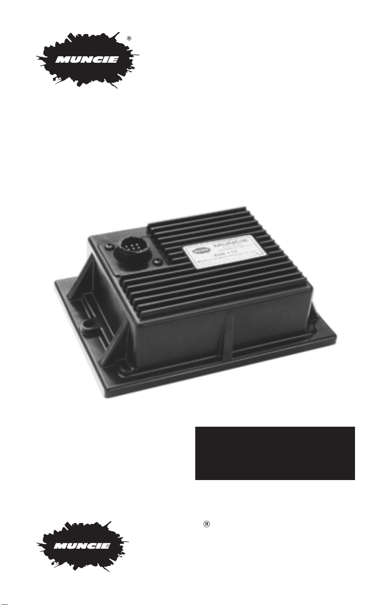
EOS-110 and parts included
These are the tools required
for installation of the EOS-110:
• Digital voltmeter
• Crimping/stripping pliers
• Screw driver .06
• Electric drill with 3/16 bit
• 3/8" socket and drive
• Standard pliers
• Hot air gun (optional)
Parts included for installation
of EOS-110 and tools required
INSTALLATION INSTRUCTIONS
Choosing a Mounting Location
The EOS-110 should be mounted in the cab. This keeps the EOS-110 away
from the harsh environment seen under the hood and allows easier one
man installation.
4
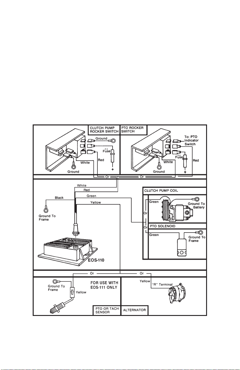
CONNECTING THE VEHICLE WIRING HARNESS
Black - Ground Wire: This wire should be attached to the truck frame. Caution:
Body attachments do not always provide good grounds.
Red - Power Input To EOS-110: Connect this line to the output terminal of the
on/off switch controlling the clutch or PTO. A 9 Amp fuse is required
in this line.**
Green - Power Output From EOS-110: (Normally open output): Connect this line
to solenoid or clutch coil.
Yellow - RPM Input To EOS-110: Connect this line to alternator ‘R’ terminal,
tachometer signal, or connect to magnetic sensor pick up on PTO unit.
White - Overspeed Indicator Light: (Normally closed output): Connect this line
to overspeed light.
**NOTE: The EOS-110 is supplied with a 9 amp fuse. Be sure there is a 9 amp
fuse in this circuit. If fuse is blown do not bypass fuse, refer to trouble
shooting guide in the back of this booklet.

5
LATE MODEL VEHICLE INSTALLATIONS
Tachometer Signal
Many engine and vehicle suppliers are providing a “clean” tachometer signal for use
by body installers. Refer to the engine supplier’s or vehicle manufacturer’s “Body
Builders Reference Books” for their recommended location for this connection. If
available use this location to connect the “Yellow” wire from our wiring harness.
EARLIER MODEL VEHICLES
Locating the Alternator “R” Terminal
The “R” terminal is the only alternator output that provides proper input signal to
the EOS-110 Electronic Overspeed Switch. This terminal is easily identifiable as
an insulated pin protrusion as shown below. If you are unable to verify this terminal visually or through use of testers, you will have to take the alternator to an
authorized service center for installation of the terminal.
Delco-Remy Alternators
CS Series Output rating: CS-121 61 & 74 amp
CS-130 85, 100, & 105 amp
CS-144 108 & 120 amp
The “P” terminal is connected to the stator. Connect
yellow EOS-110 lead to this terminal.
10 SI Series – Passenger Cars & Light Trucks
Output rating: 42-63 amp.
This series does not normally have an external “R” terminal.
Similar Series: 1251-56-94 amp
1551-85-105 amp
27 SI Series – Passenger Cars & Light Trucks
Output rating: 65-100 amp
Normally has “R” terminal in location indicated.
Similar Series: 2151-100-130 amp
25 SI Series – Line Haul Diesel & Large Gasoline Engines
Output rating: 85 amp Always has “R” terminal, usually covered
by rubber boot, in position as indicated.
Similar Series: 3051-105 amp
20 SI Series – Small to Mid-Range Diesel
& Large Gas Engines
Output rating: 60 amp
Note: 29 SI Series is same appearance,
but 90 amp rating.
40 SI Series – Extra High Output for Ambulances,
Fire Engines, Etc.
Output rating: 105-145 amp
Always has “R” terminal as indicated - covered with boot.
Terminals S, F, L, P
10 SI Series
27 SI Series
25 SI Series
20 SI Series
40 SI Series

6
Motor
craft (Ford) Alternators
D9 Series D4 Series E2 Series
2000 Series 4000 Series 7000 Series
Motorcraft Alternators have terminals marked “STA” (Stator) as indicated by the Arrows.
However, the D9 Series may not give the proper signal for the EOS-110. If step 3
of harness test is not satisfied, the alternator should be taken to an alternator service shop for modification.
Most current model Ford Alternators with a built-in, solid state regulator do not
have a “STA” terminal. They may, however, have a stator connection through one
of the connectors on the unit. Refer to the Ford body builders book or contact the
dealer for assistance.
Prestolite/ Leece-Neville Alternators are very common on many makes of small
diesel and large gas engines.
In the absence of a separate terminal, attach to the right hand terminal of the
three-in-a-row shown.
Foreign Vehicles: Foreign manufactured vehicles may have an alternator stator tap.
Some vehicles are equipped with D.C. generators (instead of alternators) and the EOS
cannot be connected to these generators. It may be possible to make the connection
by using the same signal location as the vehicle tachometer , as long as the signal input
conditions can be met. Refer to the EOS-110 specifications for these values.
Pr
estolite/Leece-Neville Alternators
Delta Connected Stator Wye Connected Stator
(Arrows Indicate Proper “R” Terminal Output)
Typical Alternator Windings

7
VEHICLE WIRING HARNESS TEST
1. Place positive (+) lead from voltmeter in the TACH calibration jack and the
negative (–) lead to frame. Set on 0-20vdc scale.
2. Start engine, advance engine to 1200 RPM and return to idle.
3. Increase and decrease engine RPM and observe voltmeter. The voltage
should increase and decrease with engine speed.
4. Place positive (+) lead from voltmeter in the engage jack. If there is no voltage then unit is not receiving current on the red wire.
5. When the engine is shut off and the PTO/clutch switch is activated the red
overspeed light should be on.
Refer to trouble shooting guide if any test fails.
EOS-110 Speed Adjustment Procedure Using a Voltmeter.
1. The EOS-110 has
test jacks to allow
adjustment by use
of a voltmeter. The
test jack voltages
will be in the 0-6
VDC range. Your
voltmeter should
be on the lowest
voltage selection
which covers the
range. Use the
positive meter
probe in the test
jacks with the
negative probe
grounded to the
truck frame.
EOS-110 INSTALLATION CHECK LIST
1. Read EOS-110 manual before installation.
2. Install vehicle wiring harness.
3. Start engine, engage PTO/clutch switch.
4. Connect Voltmeter per instructions in manual.
5. Conduct wiring harness test.
6. Set disengage speed.
7. Set engage speed.
8. Conduct functional test.
9. Disconnect Voltmeter and mount EOS-110 in
cab of vehicle.
– +
Test Jacks
TACH
CALIBRATION
ENGAGE
DISENGAGE
SERIAL NO.

8
2. Start the engine, engage the PTO/clutch switch, briefly advance the engine
to 1200 RPM and return to idle.
3. The TACH calibration will set the EOS-110’s internal tachometer circuit to
match the truck’s tachometer. This test jack voltage will rise and fall with the
engine speed, just as the vehicle’s tachometer. Use the adjustment screw to
adjust the voltmeter so that the meter displays 1.0 VDC when the truck
TACH shows 1000 RPM. The meter should then display 1.5 VDC at 1500
RPM, 2.0 VDC at 2000 RPM, etc.
4. Once you have the RPM set for 1.0 VDC per 1000 RPM turn the engine off
and return the ignition key to the “on” position.
5. Make sure there is power at the EOS-110 (overspeed light should be on).
Place the positive lead into the disengage jack. Using the disengage
adjustment screw adjust the voltmeter so that the display shows your
desired disengagement speed based on the relationship that 1.0 VDC =
1000 RPM. (Example: a disengage speed of 1800 RPM will show 1.8 VDC
on your voltmeter.)
6. Place the positive lead into the engage jack. Using the engage adjustment screw adjust the voltmeter so that the display shows your desired
re-engagement speed based on the relationship that 1.0 VDC = 1000
RPM. It is recommended that the engage be set at 1000 RPM. The engine
must idle at a speed below the engage setting in order for the unit to
function properly.
NOTE: The DISENGAGE is to be set first, then the ENGAGE. Also, when the
engine is running the ENGAGE test jack will show 6 VDC or 6000
RPM when the EOS-110 has engaged the PTO or pump. This condition is normal and no damage occurs during this condition.
7. The EOS is now calibrated. Remove the voltmeter and test the EOS with
engine running. Repeat steps 3-6 if needed.

9
Mounting the EOS-110
1. Disconnect the voltmeter or tester.
2. Use the two self-tapping machine screws supplied to mount EOS-110.
3. Plug vehicle wire harness into EOS-110.
4. There is a piece of heat shrink tubing supplied with the EOS-110 which can
be shrunk over the connector when installation is finished. This is to seal
and deter tampering with the connector.
Optional Cover
The EOS-110 can be supplied with an optional cover (074-20019) which will seal
the bottom of the EOS-110. To install this cover:
1. Remove the existing foam seal from the bottom of the EOS-110.
2. Using the 6 screws from the kit, screw the plate into place so that the
seal/gasket is facing in.
Field Replacement of the EOS-100
The EOS-110 can be used to replace the EOS-100.
Using the new wiring harness provided either make a new connection as shown
in the wiring instructions of this booklet or splice the new harness into the old by
matching wire colors. Make sure there is a fuse in the red wire circuit.
EOS-110 SPECIFICATIONS
Input Voltage .......................................... +9-18 VDC
Operating Current .................................. 20 ma
+ (Output Load)
Signal Input (Alternator) ......................... 12 Vac P-P min.
Input Frequency Range ......................... 50-1800 Hz
Output Load ...........................................
+9-18 VDC @ 5 Amp Inductive
Load Fused to 10 Amp
Operating Temp Range ..........................
–20°C To +100°C
Linearity ..................................................
±5%
Weight .................................................... 1 Lb.
EOS-111 Input Frequency Range .......... 50-3000 Hz

10
EOS-110 Trouble Shooting Guide
PROBLEM
Unit will not
engage and
overspeed light
not on
PROBABLE
CAUSE
• Blown fuse.
• Poor ground
connection.
• Reverse polarity.
• Connection,
splice or harness
connection loose.
SOLUTION
• See problem
“Blown Fuse”.
• Check crimped and
frame connections.
• Interchange red
and black leads.
• Check crimped
connections. Make
sure pin connector
is in proper alignment and ring tight.
TEST
Voltmeter
No current at
red wire.
Unit will not
engage and
overspeed light
always on
•
Alternator not
engaged.
• Incorrect alternator
terminal.
• Poor or loose
connection.
• Briefly run
engine between
1200-1500 RPM.
• See pg.5 this manual or contact dealer.
• Check crimp and
connection of
yellow wire.
Voltage at TACH
jack does
not
increase with
engine speed.
• Poor or loose
connection.
• Unit out of
adjustment.
• Check crimp and
connection of
green wire.
• See adjustment
procedure, pg. 7.
Voltage at TACH
jack does increase
and decrease with
engine speed.
• Unit out of
adjustment.
• Faulty EOS-110.
• See adjustment
procedure.
• Replace unit.
Voltage at green
wire.
Unit will not
disengage
•
Poor connection. • Check crimped and
groundconnections.
Changes in
voltage readings.
Intermittent
operation
•
Failed solenoid
coil, shorted
output lead,
faulty EOS-110.
• Examine wiring
harness and
connections for
possible short
circuits. Check
out & replace faulty
components.
Blown fuse

11
Limited Warranty
Muncie Power Products, Inc. warrants the EOS-110 or
EOS-111 to be free from defective materials and workmanship and will repair or replace, at our option, any
units found to be defective upon examination by the
Muncie Division from which the unit was purchased, for
twelve months from the date of purchase.
Units may not be returned unless specifically authorized
in writing by the Muncie Division from which the unit
was purchased.
Muncie Power Products, Inc. does not assume any
responsibility or liability for damage to any component
of the vehicle electrical system, which may result from
the installation or attempted installation of the EOS-110
or EOS-111 overspeed switch.

IN88-01 (Rev. 1-02) Printed in the U.S.A.
M
uncie
Po
w
er
Produc
t
s
Muncie Power Products, Inc. General Offices and Distribution Center
P.O. Box 548 • Muncie, IN 47308-0548 • (765) 284-7721 • FAX (765) 284-6991
E-mail info@munciepower.com • Web site http://www.munciepower.com
Drive Products, Inc., Toronto, Exclusive Agents for Canada
 Loading...