

Muncie EOS-110, EOS-111 Installation Instructions Manual
M
uncie
Po
w
er
Produc
t
s
INSTALLATION
INSTRUCTIONS
ELECTRONIC
OVERSPEED SWITCH
EOS-110 &
EOS-111

2 © Muncie Power Products, Inc. 2002
Introducing the
EOS-110 & EOS-111
The EOS-110 is an electronic switch that protects power
take-off and hydraulic equipment from operator abuse by
switching off the equipment when an excessive speed is
reached and automatically re-engages the equipment
when the engine slows to a safe speed.
The EOS-110 is equipped with a fail-safe circuit so that if
the input RPM signal is lost or not properly sensed via the
yellow wire, no output power will be available (via the green
wire) for the solenoid or clutch. This feature is beneficial in
obtaining the proper signal from the alternator and helps to
deter operator tampering.
The EOS-110 can be used as a direct replacement for the
previous model EOS-100. Refer to the installation and
adjustment procedures in this booklet and also, to the note
on Page 9.
The EOS-111 is a modified version of the EOS-110 and is
considered the same as the EOS-110 for installation purposes as described in this booklet.

3
EOS-110 PARTS LIST
QTY PART NO. DESCRIPTION
1 EOS-110 Overspeed Switch
1 074-20018 Wiring Harness
1 074-30023 Packard Terminal
1 074-20016 Small Parts Bag
EOS-110 and parts included
These are the tools required
for installation of the EOS-110:
• Digital voltmeter
• Crimping/stripping pliers
• Screw driver .06
• Electric drill with 3/16 bit
• 3/8" socket and drive
• Standard pliers
• Hot air gun (optional)
Parts included for installation
of EOS-110 and tools required
INSTALLATION INSTRUCTIONS
Choosing a Mounting Location
The EOS-110 should be mounted in the cab. This keeps the EOS-110 away
from the harsh environment seen under the hood and allows easier one
man installation.
4
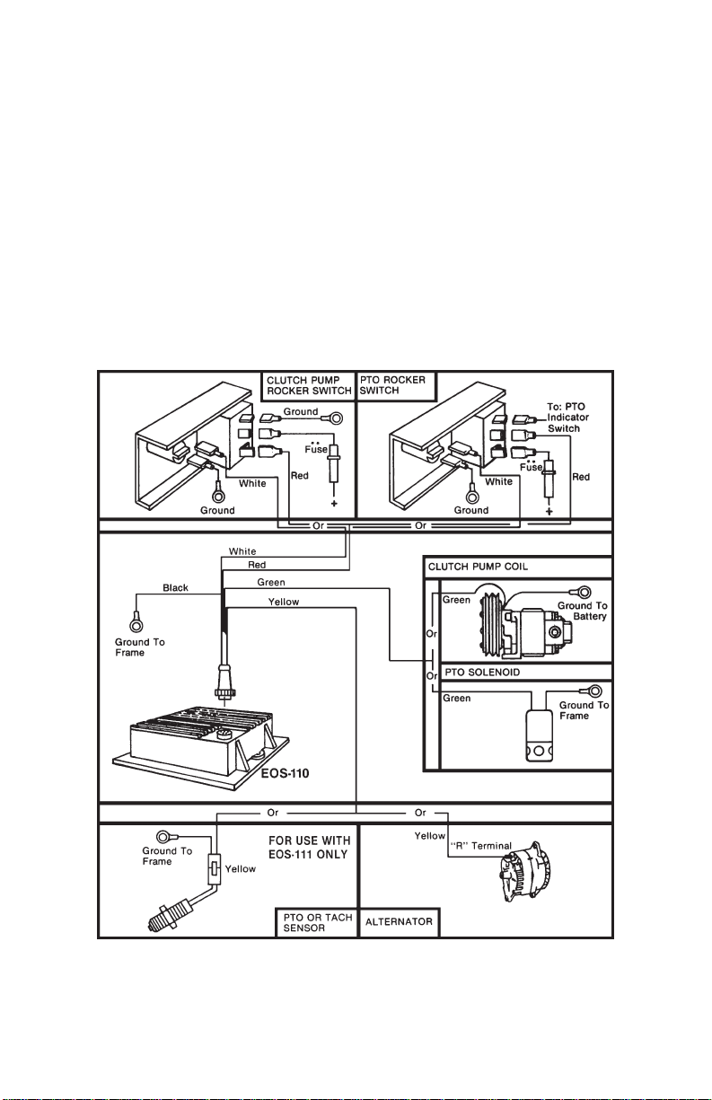
CONNECTING THE VEHICLE WIRING HARNESS
Black - Ground Wire: This wire should be attached to the truck frame. Caution:
Body attachments do not always provide good grounds.
Red - Power Input To EOS-110: Connect this line to the output terminal of the
on/off switch controlling the clutch or PTO. A 9 Amp fuse is required
in this line.**
Green - Power Output From EOS-110: (Normally open output): Connect this line
to solenoid or clutch coil.
Yellow - RPM Input To EOS-110: Connect this line to alternator ‘R’ terminal,
tachometer signal, or connect to magnetic sensor pick up on PTO unit.
White - Overspeed Indicator Light: (Normally closed output): Connect this line
to overspeed light.
**NOTE: The EOS-110 is supplied with a 9 amp fuse. Be sure there is a 9 amp
fuse in this circuit. If fuse is blown do not bypass fuse, refer to trouble
shooting guide in the back of this booklet.
 Loading...