

E/EH SERIES DUMP PUMPS
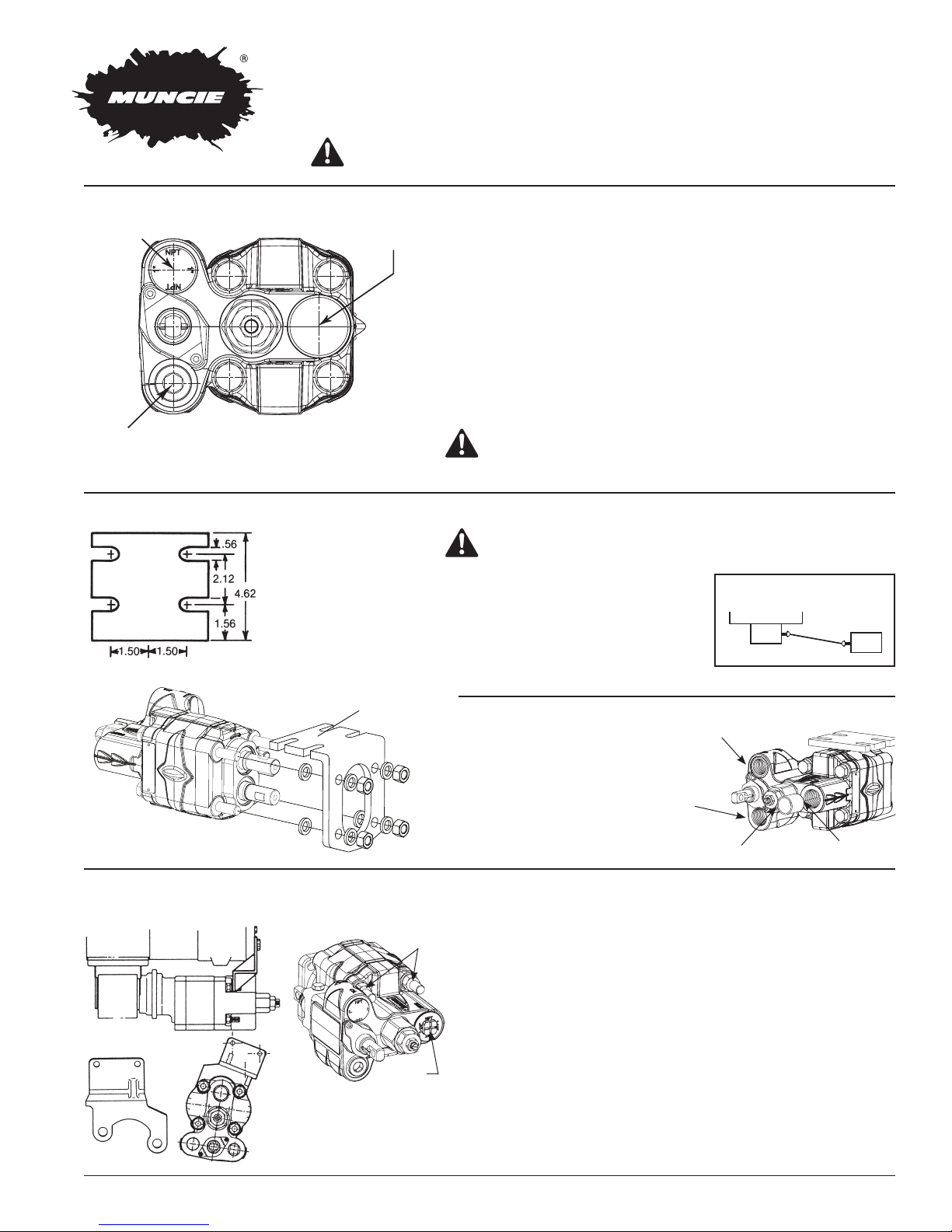
E-SERIES PORTS
1-1/2" N.P.T. (EH)
INSTALLATION INSTRUCTIONS
Product designed for dump body applications only.
DANGER:
PLUMBING INSTRUCTIONS
1" N.P.T. (E/EH)
CYLINDER
1-1/4" N.P.T. (EH)
1" N.P.T. (E)
RETURN
1-1/4" N.P.T. (E)
(INLET)
MODELS:
E – 23, 27
EH – 23, 27
MOUNTING INSTRUCTIONS – REMOTE MOUNT
Twin shafted remote mount
pumps require optional
B1235
mounting bracket No.
B1235.
Remove nuts and spacers.
Slide bracket over bolts,
replace washers and tighten
nuts. This procedure does
not open the pump.
Never work on a raised dump bed without proper body props and supports.
Do not use Teflon Tape as a thread sealant. The use of Teflon Tape
will void all warranties expressed or implied for this product.
Always use suction hose (SAE-100R4) on pump inlet.
Three line hook-up requires conversion sleeve No. AA-1257
(AA-1257-2 for the EH) in inlet port. Always route third line so it is
below the oil level at all times.
Two line hook-up has return port plugged and NO sleeve.
Port sizes are different between the E and EH. See drawing at left.
SPECIAL NOTE: For long term product life and improved pump per-
formance always use a three line hook-up. The two line system will
reduce product life. A two line system operated for extended running
times will result in excessive heat build up and subsequent damage.
CAUTION: The relief valve is pre-set at 2000 PSI ± 5%
Adjustable to (but do not exceed) 2500 PSI
WARNING: The rotating shaft between PTO and pump
should be shielded with appropriate guard.
Driveline angles should not exceed 12°.
Maximum speed for solid shafting is
1000 RPM. Consult driveline manufacturer for specifications. Pump and PTO
shafts must be parallel within 1.5°.
TOP VIEW
Transmission
PTO
PUMP
Part No. B1235A
MOUNTING INSTRUCTIONS – DIRECT MOUNT
EXAMPLES OF BRACKET CONSTRUCTION
STUDS
INLET
CONVERSION SLEEVE INSTALLATION
To convert to 3-line operation
install sleeve in inlet port. Remove
pipe plug from tank return port.
E: Part No. AA1257, EH: Part No. AA1257-2
Direct mount pumps are provided with extended studs and extra nuts
for support of pump. A bracket attached to two or more transmission
bolts is required. The bracket design should assure that there is no
stress or force exerted on the pump or PTO shaft. If vertical supports
are greater than 20° off of perpendicular with the transmission main
shaft then a reinforced “Z” bracket must be used. Reinforce horizontal members to prohibit flexing at bend or weld.
Attach the bracket at the pump bolt closest to the center of gravity
of the pump. Consult Muncie PTO Owner’s Manual for special recommendations.
Always apply anti-seize grease to shaft splines before installing into
PTO if not done by the manufacturer. Reapply annually or sooner for
severe use. PTOs with greasable shaft splines are available. Contact
Muncie Power Products for additional information.
TO CYL.
TO TANK
INLET

PULL OUT CABLES (NEUTRAL SAFETY STOP)
This clevis hole is part of a neutral stop device and is provided for
RECOMMENDED
1”
those applications using a “pull-out” cable. This device allows the
cable to move the spool from the raise position to the neutral position, only. As shock loading is possible, it is essential that a spring
be incorporated in the pull-out cable hook-up. Failure to do so could
result in breakage of the neutral stop device and could lead to injury.
We recommend that the cable be fully enclosed and directly in line
with the valve spool. Use spring part No. PS-1233V.
NOT
RECOMMENDED
NOTE: Never use a pull-out cable on an air shift pump as exact
spool position cannot be adequately controlled. Instead use
1436A-1 safety limit dump valve on raise side of air cylinder.
LEVER CONTROLS
WARNING: If valve is to be shifted by lever and rod linkage type control, the installer is responsible for fitting
the lever with a neutral locking device to prevent the accidental shifting of the valve spool and accidental
raising of the dump body. Muncie offers a complete line of in-cab consoles and controls as listed below.
Lever control rods must be attached to the spool on the front side of pump. Lever control rods cannot be attached
to the spool on the rear side due to the neutral safety stop components. On direct mount units, accessibility to the
spool eye can be improved by ordering kit No. EHK-DR (Discard unused parts).
OTHER CONTROLS DIMENSIONS IN INCHES
3.8
3.0
5.2
1.6 Typ.
4.1
1.6 Typ.
3.0
3.8
4/8/13
5.2
3.8
4.9
3.1
4.1
3.0
12
4/8/13
4.9
3.1
7.7
5.2
3.8
12
7.7
TYPE A TYPE B TYPE C, D, H TYPE E, F, G
10.0
4.3 4.3
7.0 Ref.
12.0
ASC2-**
Consoles offer within
the industry the largest
variety of dump body
feathering controls
(six models w/wo
automatic PTO kick
out and various detent
positions) with multiple
console choices for
customizing with user
accessories.
See Muncie brochure
number MP04-01 for
complete details.
Member of the Interpump Group
IN05-05 (Rev. 04-17)
800-367-7867 • Fax 765-284-6991 • info@munciepower.com • www.munciepower.com
201 East Jackson Street • Muncie, Indiana 47305
Specications are subject to change without notice. Visit www.munciepower.com
for warranties and literature. All rights reserved. © Muncie Power Products, Inc. (2010)

12.0
para mayores detalles.
Muncie número MP04-01
Consulte el folleto de
los accesorios del usuario.
se realizan a medida según
opciones de consola que
mecánico) con múltiples
posiciones de freno
7.0 Ref.
PTO y diferentes
sin dispositivo automático
volteo (seis modelos con o
controles para unidades de
más amplia variedad de
dentro de la industria la
Las consolas ofrecen
ASC2-**
10.0
IN05-05S (Rev. 04-17)
Las especicaciones están sujetas a cambios sin previo aviso. Visita www.munciepower.com
para las garantías y la literatura. Todos los derechos reservados. © Muncie Power Products, Inc. (2012)
Miembro de Interpump Hydraulics Group
800-367-7867 • Fax 765-284-6991 • info@munciepower.com • www.munciepower.com
Oficinas generales y centro de distribución • 201 East Jackson Street • Muncie, Indiana 47305
TIPO A TIPO B TIPO C, D, H TIPO E, F, G
5.2
4/8/13
3.8
1.6 Typ.
3.0
4.1
4.3 4.3
1.6 Typ.
3.0
3.8
4/8/13
3.0
12
3.8
7.7
4.1
5.2
3.1
4.9
12
3.8
5.2
7.7
3.1
4.9
OTROS CONTROLES LAS DIMENSIONES SE EXPRESAN EN PULGADAS
descarte no utilizadas).
de montaje directo, la accesibilidad a la anilla del carrete puede mejorarse mediante el pedido del equipo Nº EHK-DR (Piezas de
palanca no pueden sujetarse al carrete en la parte trasera debido a los componentes de parada de seguridad neutral. En las unidades
Los vástagos de control de la palanca deben estar sujetos al carrete en la parte frontal de la bomba. Los vástagos de control de la
cabina, tal como se enumera a continuación.
válvula y la elevación del cuerpo de volteo. Muncie ofrece una línea completa de consolas y controles incorporados a la
responsable de ajustar la palanca con un dispositivo de bloqueo neutral para evitar la activación accidental del carrete de la
ADVERTENCIA: Si se activará la válvula mediante una palanca y un control de tipo de conexión de vástago, el instalador es
CONTROLES DE PALANCA
cilindro neumático.
válvula de descarga con límite de seguridad 1436A-1 en el lado de elevación del
OBSERVACIÓN: para bombas con activación neumática de carrete. Utilice la
la pieza de resorte Nº PS-1233V.
aislamiento adecuado y directamente en línea con el carrete de la válvula. Utilice
de retorno a neutro y se instale. Recomendamos que el cable cuente con
mismo. El incumplimiento de este paso puede resultar en la rotura del dispositivo
debe utilizar un resorte para ensamblar al dispositivo para evitar la fractura del
activación de una posición de levante a una posición neutral, únicamente. Se
1”
a posición de neutro. Este dispositivo permite que el cable mueva el carrete de
Este orificio de la horquilla forma parte de un dispositivo de retorno de bomba
RECOMENDADOS
NO
RECOMENDADOS
ENSAMBLE DE CABLE A CARRETE DE ACTIVACIÓN PARA RETORNO A POSICIÓN DE NEUTRO

Power Products.
1" N.P
CILINDR
1-1/4" N.P
1" N.P
RETORNO
eje engrasables. Para mayor información, comuníquese con Muncie
extremos. Se encuentran disponibles dispositivos PTO con ranuras de
fabricante. Vuelva a aplicarla en forma anual o antes, en caso de usos
de instalarlo en el PTO, en caso de que no haya sido realizado por el
Siempre aplique grasa anti-agarrotamiento a las ranuras del eje antes
especiales.
Manual del Propietario de PTO Muncie para obtener recomendaciones
pernos de la transmisión con soporte en una sola pieza. Consulte el
Sujete el soporte a los dos pernos superiores de la bomba y a dos
arqueamiento o soldadura.
Refuerce los miembros horizontales para evitar la flexión durante el
el eje de transmisión principal, se debe utilizar un soporte “Z” reforzado.
PTO. Si los soportes verticales superan los 20º de perpendicularidad con
asegurar que no haya tensión o presión ejercida en la bomba o el eje
sujetado a dos o más pernos de transmisión. El diseño del soporte debe
y tuercas adicionales para el soporte de la bomba. Se requiere un soporte
Las bombas de montaje directo están equipadas con pernos extendidos
ALIMENTACIÓN
PERNOS EXTENDIDOS
EJEMPLOS DE CONSTRUCCIÓN DE SOPORTES
INSTRUCCIONES DE INSTALACIÓN: MONTAJE DIRECTO
BOMBA
ALIMENTACIÓN
AL CILINDRO
PTO
Transmisión
VISTA SUPERIOS
VISTA LATERAL
E: Pieza Nº AA1257, EH: Pieza Nº AA1257-2
HACIA EL TANQUE
SAE1 00R4 al tanque.
conexión y manguera SAE 100R1 o
tapón del puerto de retorno e instale
el puerto de alimentación. Retire el
2 a tres líneas, instale el buje en
Para convertir a una operación de
INSTALACIÓN DEL BUJE DE CONVERSIÓN
paralelos a menos 1.5°.
las especificaciones. Los ejes de la bomba y toma de fuerza deben ser
fabricante del sistema de transmisión para
máxima 1000 RPM eje sólido. Consulte al
no deben superar los 12°. Velocidad
cada caso en particular. Los ángulos
requiere de un diseño específico para
La utilización de un eje remoto cardán
protección adecuada.
transferencia de potencia) y la bomba debe cubrirse con una
ADVERTENCIA: El eje cardan entre el PTO (Dispositivo de
PSI + o - 5% Ajustable a 2500 PSI (sin exceder este límite)
PRECAUCIÓN: La válvula de alivio se calibra de fábrica a 2000
prolongados generará un aumento de calor y daño posterior.
El sistema de dos líneas operado durante períodos de ejecución
tres líneas. El sistema de dos líneas reducirá la vida útil del producto.
mejorar el rendimiento de la bomba siempre utilice una conexión de
• OBSERVACIÓN ESPECIAL: Para prolongar la vida útil del producto y
esquema de la izquierda.
• El tamaño de los puertos varía entre las series E y EH. Véase el
y no incluye el buje para sistema de tres líneas.
• La conexión de dos líneas tiene el puerto de retorno al tanque sellado
retorno al tanque quede en la parte inferior respecto al puerto al cilindro.
Siempre instale la bomba de volteo de tal forma que el puerto de
Nº AA-1257 (AA-1257-2 para la serie EH) en el puerto de alimentación.
• El sistema de tres líneas requiere para la serie E un buje de conversión
de la bomba.
• Siempre utilice una manguera (SAE-100R4) en el puerto de alimentación
implícitas de este producto.
hidráulicas. La utilización de teflón anulará todas las garantías expresas e
• No utilice teflón liquido o en cinta como sellador para conexiones
Pieza Nº B1235A
bomba.
procedimiento no abre la
ajuste las tuercas. Este
reemplace las arandelas y
soporte sobre los pernos,
espaciadores. Deslice el
Retire las tuercas y los
B1235
.T. (E)
.T. (EH)
O
.T. (E/EH)
EH – 23, 27
E – 23, 27
MODELOS:
(ENTRADA)
(ALIMENTACIÓN)
1-1/4" N.P.T. (E)
1-1/2" N.P.T. (EH)
montaje adicional, Nº B1235.
requieren un soporte de
remoto con doble eje
Las bombas de montaje
HIDRÁULICAS Y MANGUERAS
Aseg
ú
rese de colocar soportes fisicos adecuados para el cuerpo de volteo.
PELIGRO: Nunca trabaje en una unidad con el cuerpo de volteo elevado.
INSTRUCCIONES DE INSTALACIÓN: MONTAJE REMOTO
INSTRUCCIONES PARA INSTALACIÓN DE CONEXIONES
Producto diseñado para aplicaciones de volteo únicamente.
INSTRUCCIONES DE INSTALACIÓN
BOMBAS DE VOLTEO SERIE E/EH
 Loading...