

Page 1

Padlock
Service Manual
Page 2

Page 3

Table of Contents
E Series Padlock ...........................................................................2
Protected shackle .............................................................................3
Disassembly Instructions ..................................................................4
Assembly Instructions .......................................................................6
Sliding Bolt (SBE) ...........................................................................9
Disassembly Instructions ................................................................10
Assembly Instructions .....................................................................12
C Series Padlock .........................................................................13
Removable Shackles 10, 13 & 16 ...............................................13
Removable Shackle ........................................................................14
Disassembly Instructions ................................................................14
Pop-Open Shackles 10, 13 & 16 .................................................16
Disassembly Instructions ................................................................17
Conversion between Removable Shackle
and Pop-Open Shackle ..................................................................19
Pop-Open Shackle No. 8 ............................................................... 20
Disassembly Instructions ................................................................21
Cylinder Service .............................................................................22
Single Pin ..........................................................................................23
Disassembly Instructions ................................................................24
SBC-13 Sliding Bolt ......................................................................26
Disassembly Instructions ................................................................27
G Series Padlock .........................................................................30
Padlock G-47 ....................................................................................30
Padlock G-47P ................................................................................. 31
Padlock G-55 ....................................................................................32
Padlock G-55P ................................................................................. 33
Padlock G-60 ....................................................................................34
G Series Padlock ............................................................................35
Assembly Instructions .....................................................................35
Security Pin ......................................................................................37
Assembly Instructions .....................................................................37
Sliding Bolt (SBG) .........................................................................38
Disassembly & Assembly Instructions.............................................39
Round Padlock ............................................................................... 42
Hockey Puck Type ......................................................................... 42
Page 4
2
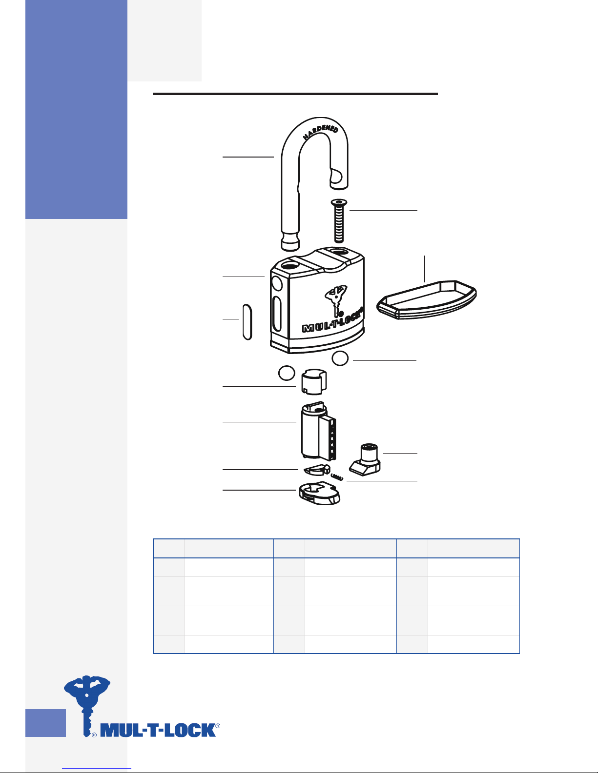
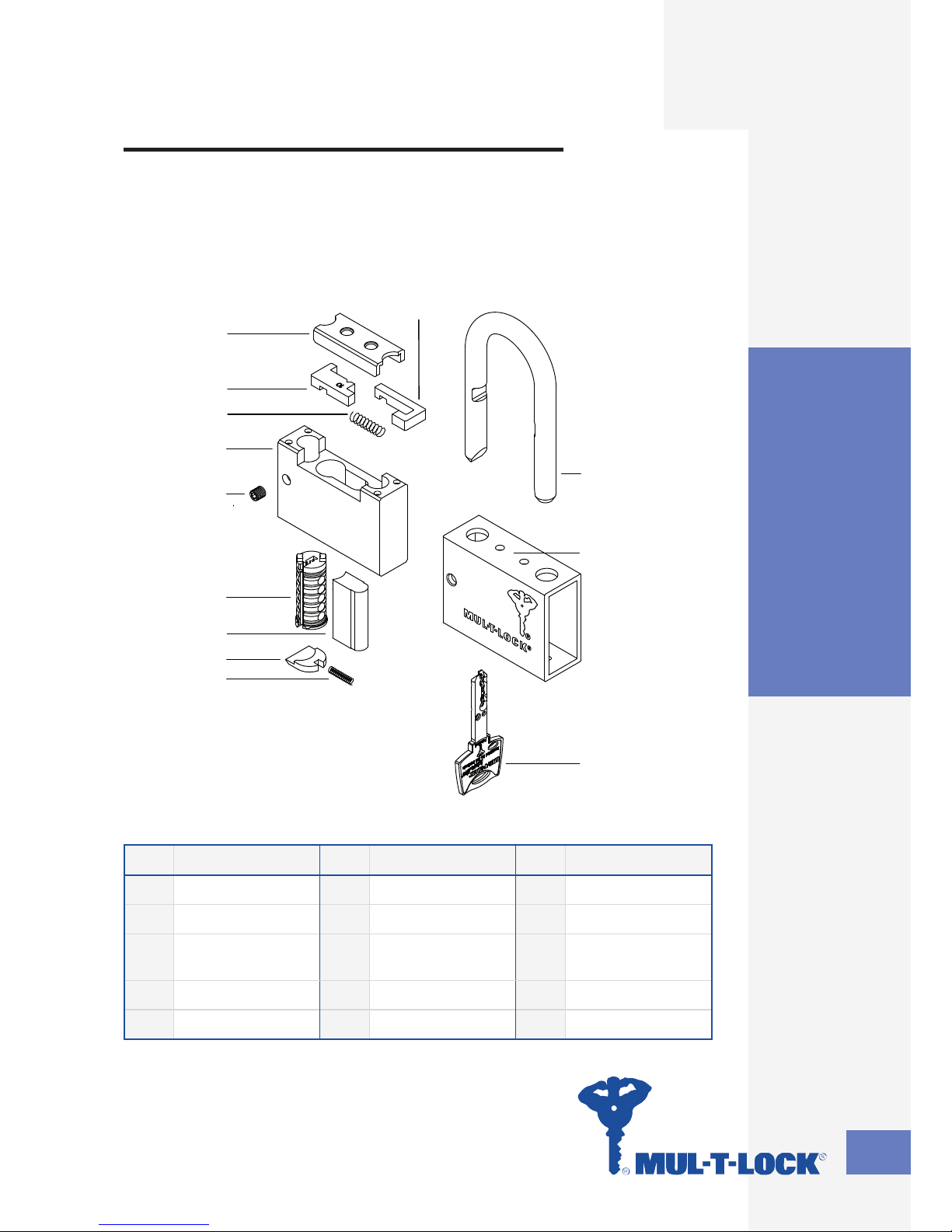
E Series Padlock
E Series Padlock
No. Part No. Part No. Part
1 Padlock body 5 Locking plate 9 Ball St. Steel
2 Shackle 6 Bumper 10
Socket head
screw
3 Activator cam 7
Identification
plate
11 Spring for shutter
4 Body cover 8 Unified shutter 12 Cylinder
1
2
3
4
5
6
7
8
9
10
11
12
Page 5

3
E Series Padlock
Protected shackle
No. Part No. Part No. Part
1 Padlock body 5 Locking plate 9 Ball St. Steel
2 Shackle 6 Bumper 10
Socket head
screw
3 Activator cam 7
Identification
plate
11 Spring for shutter
4 Body cover 8 Unified shutter 12 Cylinder
Protected shackle
1
2
3
4
5
6
7
8
9
10
11
12
Page 6

4
E Series Padlock
4
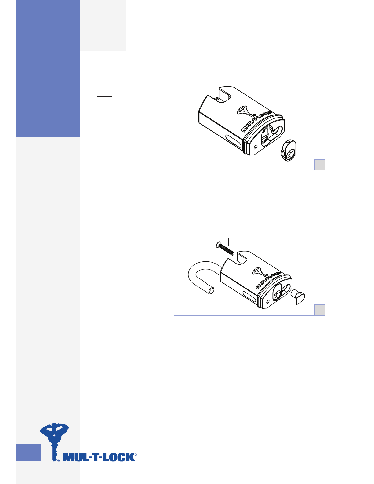
Disassembly Instructions
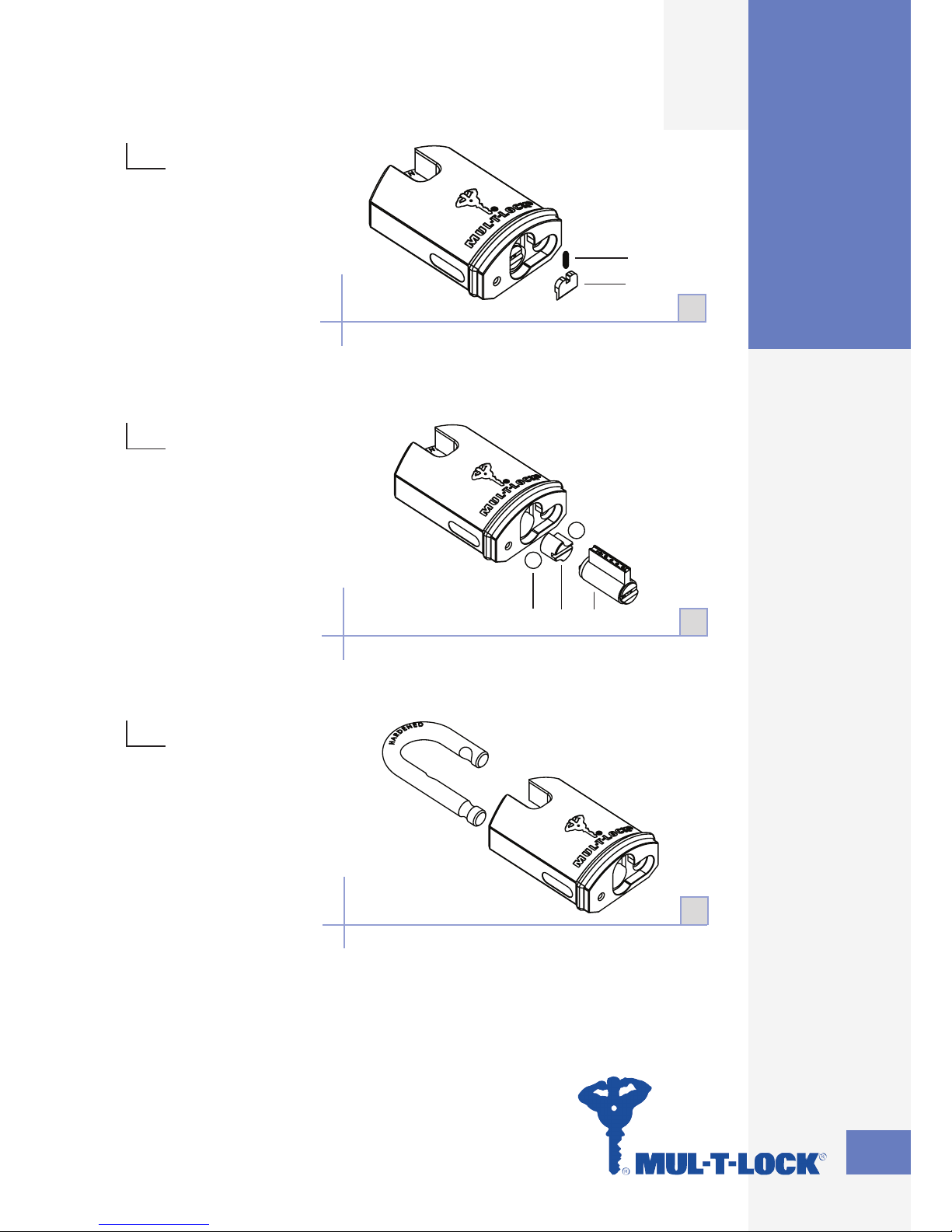
1
Unlock the padlock
with the operating
key.
Unscrew one socket
head screw (10)
using 3 mm “allen”
key. Remove locking
plate (5).
•
•
2
Lock the padlock with the
operating key.
Take operating key out and
remove body cover (4).
•
•
2
Protected shackle / Disassembly Instructions
1
510
Page 7
5
E Series Padlock
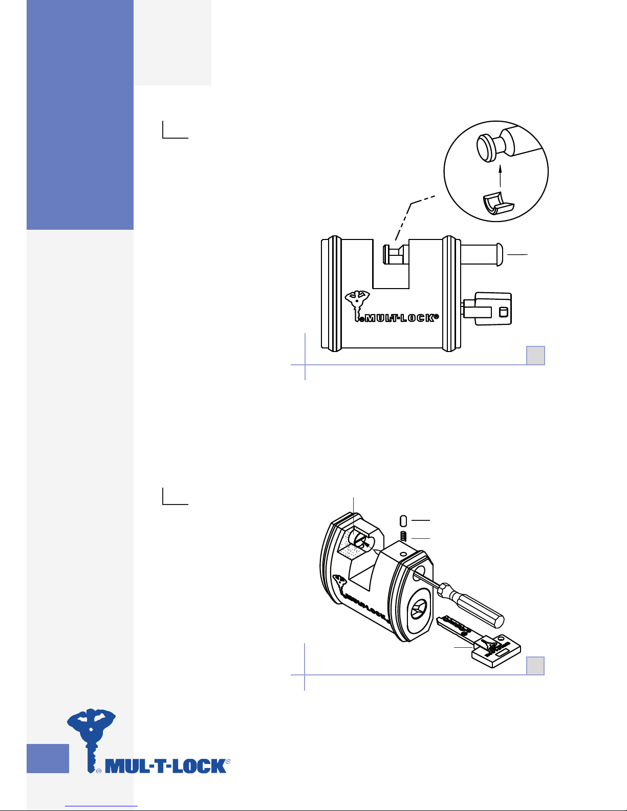
3
Remove shutter spring
(11) and shutter (8).
•
4
Remove cylinder (12),
activator cam (3)
and two ball bearings (9).
•
5
Remove shackle (2).•
5
Protected shackle / Disassembly Instructions
8
11
3
4
12
9
3
Page 8
6
E Series Padlock
3-A
Assembly Instructions
1
Insert shackle (2) in the position as illustrated.
NOTE: Pay special attention to shackle
position (height and rotation)!
•
•
2
Insert two ball bearings (9).
Insert activator cam (3) in shown position.
NOTE: Activator cam (3) is not symmetrical.
See diagram 3-A.
•
•
•
Protected shackle / Assembly Instructions
9
3
2
Smaller
groove
toward the
longer leg of
the shackle
1
2
Page 9
7
E Series Padlock
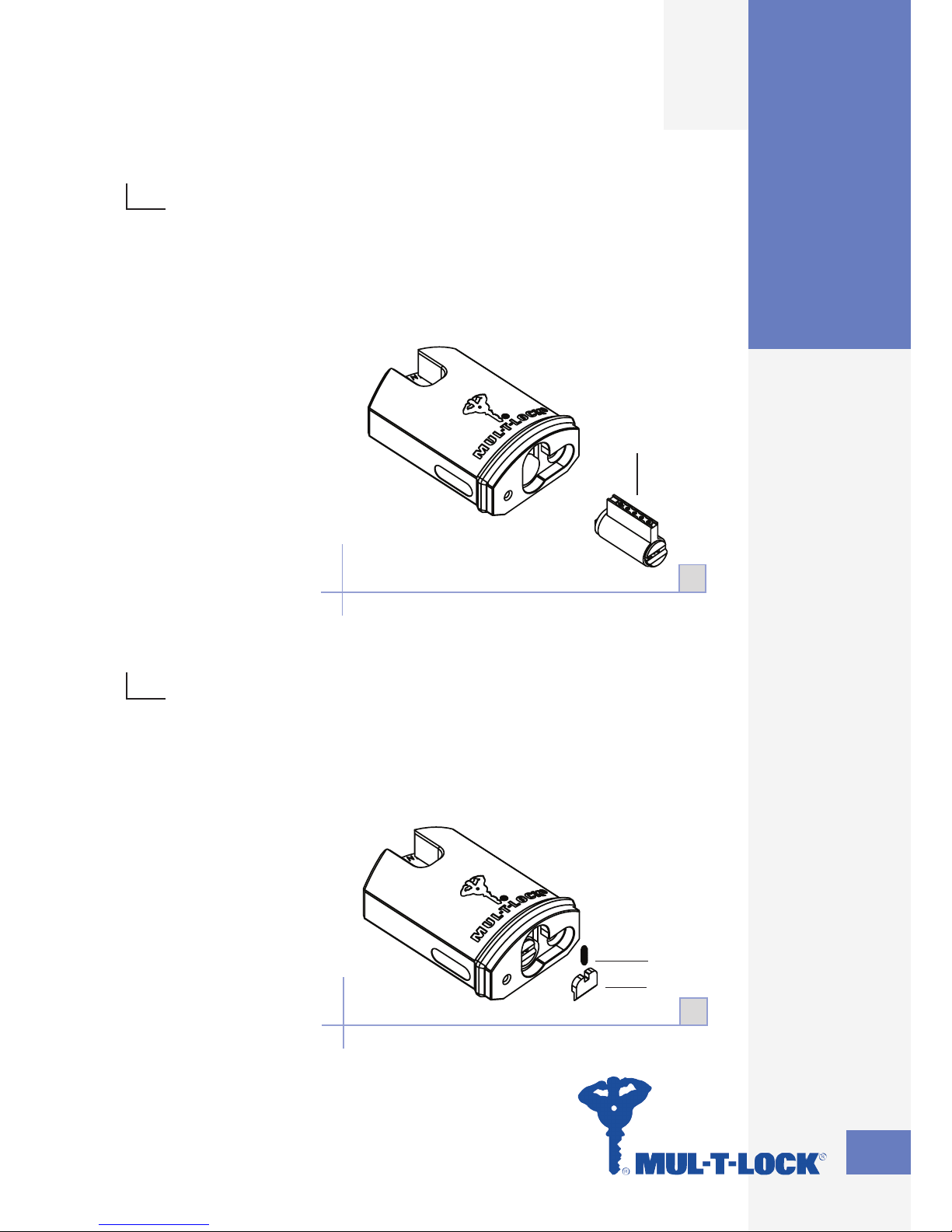
3
Insert cylinder (12).
Insert operating key and rotate the
cylinder until it reaches the right
position.
•
•
4
Lock cylinder (12) and remove
operating key.
Install shutter (8) and shutter
spring (11).
•
•
Protected shackle / Assembly Instructions
8
11
4
12
3
Page 10
8
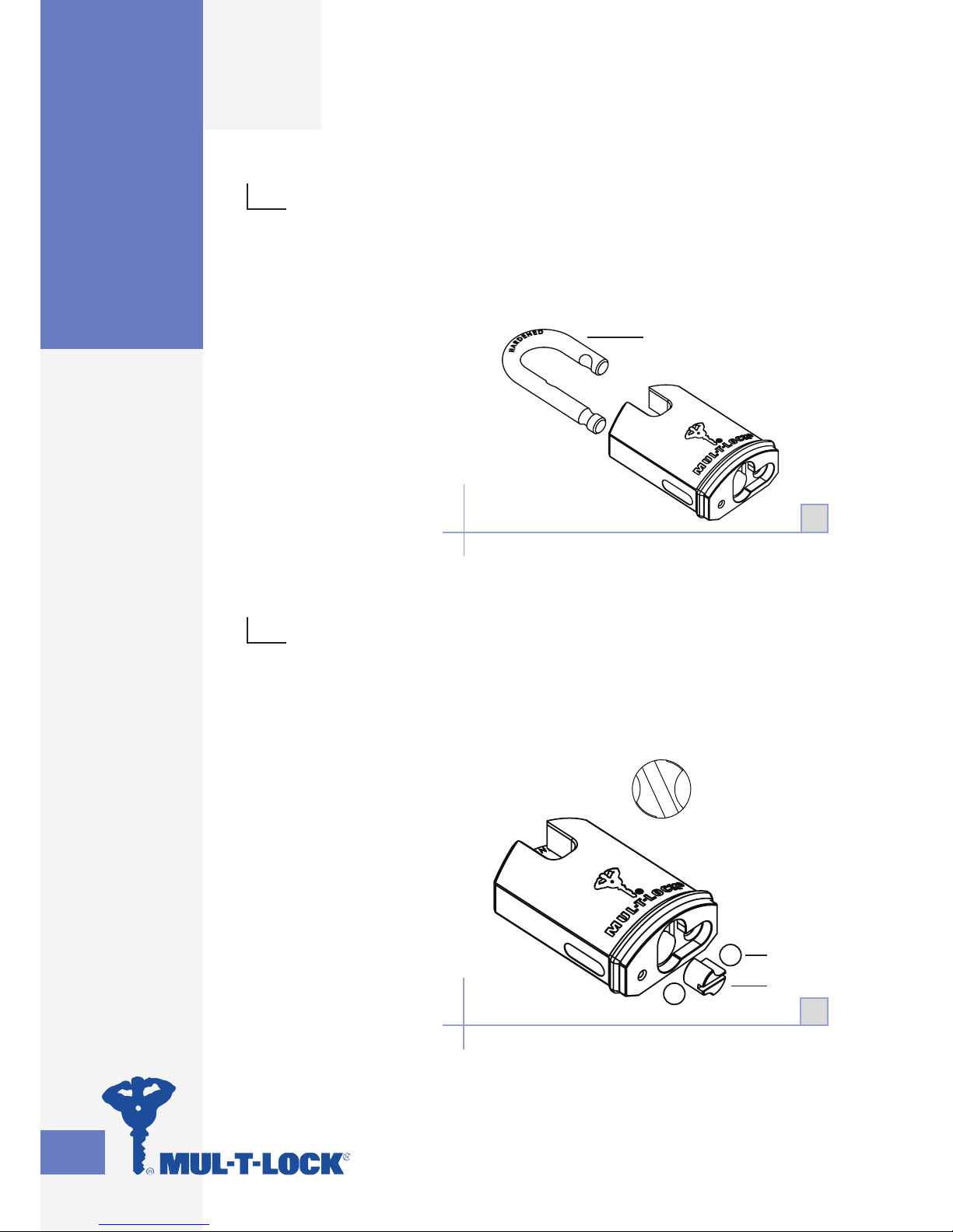
E Series Padlock
6
Install body cover
(4).
•
7
Insert operating key
and unlock shackle (2).
Install locking plate (5).
Using 3 mm “allen” key
tighten the socket head
screw (10).
•
•
7
Protected shackle / Assembly Instructions
4
6
5102
Page 11

9
E Series Padlock
1
2
3
4
5
6
789
10
11
12
13
14
15
16
17
18
19
20
21
Sliding Bolt (SBE)
No. Part No. Part No. Part
1 Key 8 Activator cam 15 Pin
2
Cylinder front
cover
9 Ball bearing 5 mm 16 Bolt pusher
3 Ball bearing 4 mm 10 Latch hole plug 17 Plastic bumper
4 Shutter spring 11 Spring 18 Bolt stopper
5 Shutter 12 Latch 19
Socket set screw
with cone point
6 Cylinder 13 Lock body 20
Spring for bolt
stopper
7
Socket set screw
with cone point
14 Spring 21 Bolt
Sliding Bolt (SBE)
Page 12
10
E Series Padlock
Disassembly Instructions
21
1
1
Unlock the padlock with
operating key.
Mount on the bolt
disassembling ring and
remove the bolt (21)
by pulling it out.
•
•
2
Take out pin and spring
(18,20).
Using screwdriver push the
bolt pusher (16) until the
latch (12) pops up.
Take out the key (1).
•
•
•
Sliding Bolt (SBE) / Disassembly Instructions
2
18
20
1
16
Page 13
11
E Series Padlock
17
468
5
19
2
3
10
11
12
7
9
4
3
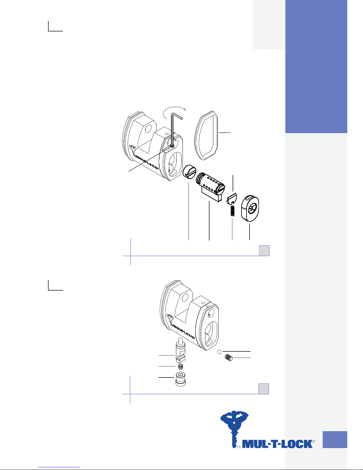
Remove bumper (17).
Using 2.5 mm “allen” key insert into hole (located beneath bumper)
and loosen screw (19) until until the cylinder cover can be removed (Do
not disassemble completely).
Remove cylinder front cover (2), shutter spring (4) and shutter (5).
Take out cylinder (6) and activator cam (8).
•
•
•
•
4
NOTE:
It is not needed to
disassemble the locking
mechanism for re-keying!
Assembly tip
Check that the
mechanism works
properly before inserting
the bolt!
•
•
Sliding Bolt (SBE) / Disassembly Instructions
Page 14
12
E Series Padlock
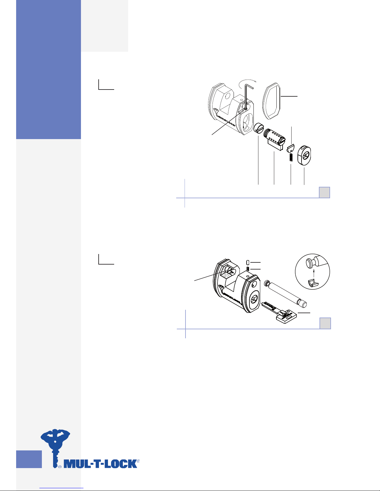
Assembly Instructions
17
2468
5
19
1
1
Install activator cam (8)
and cylinder (6).
Install shutter spring (4)
and shutter (5).
Place cylinder front
cover (2) using 2.5
mm “allen” key, tighten
screw (19).
•
•
•
2
Install pin and
spring (18,20). Push
them back with a
screwdriver until the
shackle is inserted.
Insert key and check
for smooth operation.
NOTE: you may need
to push bolt pusher
(16) in order to turn
the key.
•
•
•
Sliding Bolt (SBE) / Assembly Instructions
18
20
1
16
2
Page 15
13
C Series Padlock
6
3
7
8
9
12
13
4
2
1
11
10
5
C Series Padlock
Removable Shackles
10, 13 & 16
No. Part No. Part No. Part
1 Key 6 Short latch 11 Hive
2 Shell 7 Latch spring 12 Dust shutter
3 Shackle 8 Core 13
Dust shutter
spring
4 Long latch 9 Set screw M5
5 Thrust plate 10 Plug
Removable Shackles 10, 13 & 16
Page 16

14
C Series Padlock
Removable Shackle
Disassembly Instructions
2
3
9
1
8
13
12
5
7
6
4
2
1
Unlock the padlock
with the operating key.
Using a 2.5 mm “allen”
key, remove the set
screw (9).
Remove shackle (3).
•
•
•
2
Take the key out.
Slide out core (8),
making sure to
carefully set aside the
spring-loaded parts
(4,5,6,7,12,13).
•
•
Removable Shackle / Disassembly Instructions
Page 17

15
C Series Padlock
3
Turn the core upside down and pull
out the cylinder so that the plastic
catch can be mounted.
NOTE: Do not pull the cylinder out of
the core more than two-thirds of
the way!
Mount the plastic catch and remove
the cylinder.
•
•
•
4
Insert the key into the
cylinder and turn it until
the pins can be removed
from the plug.
•
CA B
3
4
Removable Shackle / Disassembly Instructions
Page 18

16
C Series Padlock
6
3
7
8
9
10
13
14
4
2
1
12
11
5
15
Pop-Open Shackles
10, 13 & 16
No. Part No. Part No. Part
1 Key 6 Thrust plate 11 Plug
2 Shell 7 Short latch 12 Hive
3 Shackle spring 8 Latch spring 13 Dust shutter
4 Shackle 9 Core 14 Spring
5 Long latch 10
Threaded pin
10/32" UNF
15 Hardened pin
Pop-Open Shackles 10, 13 & 16
Page 19

17
C Series Padlock
Disassembly Instructions
4
2
10
3
1
9
14
13
15
6
8
7
5
1
Unlock the padlock with
the operating key.
Using a 2.5 mm “allen”
key, remove the
threaded pin (10).
Remove shackle (4)
and spring (3).
•
•
•
2
Take the key out.
Slide out core (9),
making sure to
carefully set aside
the spring-loaded
parts (5, 6, 7, 8, 13,
14, 15).
•
•
Pop-Open Shackle / Disassembly Instructions
2
Page 20

18
C Series Padlock
A
B C
3
4
3
Turn the core upside down and pull
out the cylinder so that the plastic
catch can be mounted.
NOTE: Do not pull the cylinder out
of the core more than two-thirds of
the way!
Mount the plastic catch and remove
the cylinder.
•
•
•
4
Insert the key into the
cylinder and turn it until the
pins can be removed from
the plug.
•
Pop-Open Shackle / Disassembly Instructions
Page 21

19
C Series Padlock
Conversion between Removable
Shackle and Pop-Open Shackle
1
To convert a removable shackle lock into
a pop open shackle lock, change set
screw (9R) to socket threaded pin (10P).
Replace removable shackle (3R) with
pop-open shackle (4P).
Add hardened pin (15P) and spring (3P).
2
To convert a pop-open shackle lock
into a removable shackle lock, change
threaded pin (10P) to set screw (9R).
Replace pop-open shackle (4P) with a
removable shackle (3R).
Remove hardened pin (15P) and
spring (3P).
NOTE:
R: removable shackle part
P: pop-open shackle part
For assembly, refer to
Assembly Instructions and
Exploded Views pages for
types P and R.
•
•
•
•
•
•
•
•
4P
10P
3R
15P
9R
3P
Conversion between Removable Shackle and
Pop-Open Shackle
Page 22

20
C Series Padlock
6
3
7
8
9
10
13
14
4
2
1
12
11
5
No. Part No. Part No. Part
1 Key 6 Thrust Plate 11 Plug
2 Shell 7 Short latch 12 C8 Hive
3 Shackle Spring 8 Latch Springs 13 Shutter
4 Shackle 9 Core 14 Shutter Spring
5 Long latch 10
Threaded pin
10/32" UNF
Pop-Open
Shackle No. 8
Pop-Open Shackle No. 8
Page 23

21
C Series Padlock
Disassembly Instructions
1
Unlock the padlock with
the operating key.
Using a 2.5 mm “allen”
key, remove the threaded
pin (10).
Remove shackle (4)
and spring (3).
•
•
•
4
2
10
3
9
14
13
15
6
7
8
5
2
Take key out.
Slide out core (9),
making sure to carefully
set aside the springloaded parts
(5, 6, 7, 8, 13, 14, 15).
•
•
1
2
Pop-Open Shackle No. 8 /
Disassembly Instructions
Page 24

22
C Series Padlock
3
Turn the core upside down and pull out the
cylinder so that the plastic catch can be
mounted.
NOTE: Do not pull the cylinder out of the
core more than two-thirds of the way!
Mount the plastic catch and remove the
cylinder.
•
•
•
CBA
3
4
4
Insert the key into the cylinder and
turn it until the pins can be removed
from the plug.
•
Cylinder Service
Pop-Open Shackle No. 8 / Cylinder Service
Page 25

23
C Series Padlock
6
3
7
8
9
10
4
13
4
2
1
12
11
5
14
15
16
Single Pin
No. Part No. Part No. Part
1 Key 7 Thrust plate 13 Plug
2 Shell 8 Long latch 14 Shutter
3 Locking pin 9 Latch spring 15 Shutter spring
4 O - Ring 10 Core 16 Hive
5 Pin 11 Set screw M5
6 Short latch 12 Lower pin
Single Pin
Page 26

24
C Series Padlock
Disassembly Instructions
7
10
6
2
9
8
12
15
16
4, 5
2
1
Unlock the padlock
with
the operating key.
Using a 2.5mm “allen”
key, remove the set
screw (11).
Remove locking
pin (3).
•
•
•
2
Take key out.
Slide out core (10), making
sure to carefully set aside the
spring-loaded parts
(6,7,8,15,16).
Remove pins
(4,5,12).
•
•
•
2
11
3
2
Single Pin / Disassembly Instructions
Page 27

25
C Series Padlock
A B C
3
4
3
Turn the core upside down and pull
out the cylinder so that the plastic
catch can be mounted.
NOTE: Do not pull the cylinder out of
the core more than two-thirds of the
way!
Mount the plastic catch and remove
the cylinder.
•
•
•
4
Insert the key into the cylinder and
turn it until the pins can be removed
from the plug.
•
Single Pin / Disassembly Instructions
Page 28

26
C Series Padlock
12
3
5
4
8
121013 1461511 16
15
18
17
19
7
20
9
SBC-13 Sliding Bolt
PartNo.PartNo.PartNo.
Steel pin15Bolt8
Rear protecting
plate
1
Set screw M4x416Plug9Shell2
Grooved pin17Dust shutter10Spring3
Spring18
Front protecting
plate
11Bolt pusher4
Spring19Spring12Core5
Latch20Hive13Stopper6
Adaptor14Spring7
SBC-13 Sliding Bolt
Page 29

27
C Series Padlock
Disassembly Instructions
8
1
1A
6
17
7
2
1
Unlock the padlock
with the operating key.
Mount the
disassembling ring
onto the bolt as
illustrated (1A).
Remove the bolt (8) by
pulling it out.
•
•
•
2
Remove pin (6) and
spring (7).
Push grooved pin (17)
up while sliding core out.
•
•
SBC-13 Sliding Bolt / Disassembly
Instructions
Page 30

28
C Series Padlock
3
Remove grooved pin (17)
and spring (19).
To take key out, apply
force on spring (18), insert
screwdriver and push
inside bolt pusher (4).
Key will return to closed
position and can be
taken out.
•
•
•
1
3
4
15
12 11
16
15
15
16
10
4
4
Remove three pins (15) and two
screws (16).
Remove parts 1, 3, 4, 10, 11, 12.
•
•
18
17
19
3
SBC-13 Sliding Bolt / Disassembly
Instructions
Page 31

29
C Series Padlock
20
14
A B C
5
6
5
Turn the core upside down and pull
out the cylinder so that the plastic
catch can be mounted.
NOTE: Do not pull the cylinder out of
the core more than two-thirds of the
way!
Mount the plastic catch and remove
the cylinder.
•
•
•
6
Insert the key into the cylinder and
turn it until the pins can be removed
from the plug.
Assembly tip
Latch (20) goes inside before
adaptor (14).
•
•
SBC-13 Sliding Bolt / Disassembly
Instructions
Page 32

30
G Series Padlock
8
6
3
2
1
10
9
4
5
7
G Series Padlock
Padlock G-47
No. Part No. Part No. Part
1 Key 5 Latch* 9 Shackle
2 Cylinder 6 G-47 body 10
Ball bearing
8 mm
3 Cam limiter 7 Security pin
4 Cam activator 8 Screw M4x10
* Elongated ball bearing
Padlock G-47
Page 33

31
G Series Padlock
8
6
3
2
10
9
4
5
7
1
Padlock G-47P
No. Part No. Part No. Part
1 Key 5 Latch* 9 Shackle
2 Cylinder 6 G-47 body 10
Ball bearing
8 mm
3 Cam limiter 7 Security pin
4 Cam activator 8 Screw M4x10
* Elongated ball bearing
Padlock G-47P
Page 34

32
G Series Padlock
8
6
3
2
1
5
9
4
5
7
Padlock G-55
No. Part No. Part No. Part
1 Key 4 Cam activator 7 Security pin
2 Cylinder 5 Latch* 8 Screw M4x10
3 Cam limiter 6 G-55 body 9 Shackle
*Elongated ball bearing
Padlock G-55
Page 35

33
G Series Padlock
8
6
3
2
1
5
9
4
5
7
Padlock G-55P
Padlock G-55P
No. Part No. Part No. Part
1 Key 4 Cam activator 7 Security pin
2 Cylinder 5 Latch* 8 Screw M4x10
3 Cam limiter 6 G-55 body 9 Shackle
*Elongated ball bearing
Page 36

34
G Series Padlock
8
6
3
2
1
5
9
4
5
7
Padlock G-60
Padlock G-60
No. Part No. Part No. Part
1 Key 4 Cam activator 7 Security pin
2 Cylinder 5 Latch* 8 Screw M4x10
3 Cam limiter 6 G-60 body 9 Shackle
*Elongated ball bearing
Page 37

35
G Series Padlock
6
9
10
5
1
4
2A
2
G-Series Padlock
Assembly Instructions
G-Series Padlock / Assembly Instructions
These assembly instructions are intended to walk you through the
assembly process, starting with the padlock disassembled. If you
start dismantling an assembled lock, please refer to the next page for
instructions on removing the security pin.
1
With the shackle (9)
inside, hold the padlock
body (6) upside-down.
Push the two elongated
ball bearings (5 for G-55
padlocks; 5 & 10 for
G-47 padlocks) through
the cylinder opening,
one per side.
NOTE: For G-47
models, ensure that
the elongated ball
bearing (5) is placed in
the direction of the short
leg of the shackle (2A).
•
•
•
2
Insert the padlock
activator via the
cylinder opening.
NOTE: For G-47
models make sure
that the deepest
groove is facing
the short leg of the
shackle.
•
•
Page 38

36
G Series Padlock
8
7
4
3
2
3
3
Insert the cam limiter (3),
ensuring that it engages
with the protrusion of the
activator (4).
Insert the cylinder (2) into
its place, making sure
that the key will be at it’s
removal point when the
padlock is locked.
•
•
4
Put the cylinder
holding screw (8) into
its place. In order to
prevent it from working
loose, secure it with a
drop of “LOCTITE”.
For additional safety,
use the security pin
(7) as described on
the next page.
•
•
G-Series Padlock / Assembly Instructions
Page 39

37
G Series Padlock
Security Pin
Assembly Instructions
1
Unlock the padlock
with the operating key.
Reach for the cylinder
mounting screw
through the shackle
hole with a Philips
screwdriver, release
and remove it. This will
not release the cylinder,
which is still held by the
security pin.
•
2
Once the screw is
out, use a punch and
drive in the pin, which
will fall into the cavity
above the cylinder. The
cylinder can now be
removed, and you can
recover the pin for reassembly.
•
3
Assemble the cylinder
in position with the
mounting screw and
tighten. Check the lock
for correct operation.
Once confirmed, drive
the security pin home
with a small hammer.
The pin end should
be flush with body
outer surface as per
Figure 1.
•
1
2
3
Security Pin / Assembly Instructions
Page 40

38
G Series Padlock
Sliding Bolt (SBG)
Sliding Bolt (SBG)
No. Part No. Part No. Part
1 Key 5
Ball bearing
8 mm
9 Bolt retaining pin
2 Cylinder 6 Locking bolt pin 10 Socket screw M5
3 Cam limiter 7 Sliding bolt 11 Lock body
4 Activator cam 8
Bolt retaining pin
Spring
12
34
8
9
10
11
6
5
7
Page 41

39
G Series Padlock
7
1
1
2
3
Disassembly & Assembly
Instructions
Sliding Bolt (SBG) /
Disassembly & Assembly Instructions
1
Unlock the padlock
with the operating
key (1).
Mount on the bolt
(7) disassembling
ring and remove the
bolt by pulling it out.
•
•
2
Take out pin and spring
(8,9).
Take out the key (1).
•
•
3
Using 2.5 mm “allen”
key insert into hole and
loosen the screw (10).
Now the cylinder is
free, via opening in
side remove cylinder
and inner parts of
the body.
Disassembling of the
locking mechanism
is not needed for
re-keying.
•
•
•
8
9
2
10
Page 42

40
G Series Padlock
9
6
With the bolt push the
follower out.
Assembly tip
Check that the
mechanism function
properly before
inserting the bolt!
•
•
4
5
Sliding Bolt (SBG) /
Disassembly & Assembly Instructions
4
Via the opening in
side remove inner
parts of the body
(3,4,5,6).
NOTE: Disassembling
the locking
mechanism is not
needed for re-keying.
•
•
5
After re-keying the
cylinder insert all the
inner parts and fasten
the screw (3, 4, 5, 6)
•
34
6
5
Page 43

41
G Series Padlock
6 5
4
3 2
7
1
Round Padlock
Hockey Puck Type
No. Part No. Part No. Part
1 Key 4 Connecting Pin 7 Screw
2 Cylinder 5 Bolt
3 Cylinder Base 6 Padlock Body
Round Padlock
Hockey Puck Type
Page 44

NOTES
Page 45

Page 46

Page 47

Page 48

An ASSA ABLOY Group brand
With its readiness to rapidly respond to any challenge,
Mul-T-Lock ensures peace of mind by delivering
comprehensive, customized, top security cylinder
locking solutions and services worldwide.
ASSA ABLOY is the global leader in door opening
solutions, dedicated to satisfying end-user needs
for security, safety and convenience.
The Mul-T-lock name and Muscleman Logo, and any other name, mark or logo used by Mul-T-Lock and marked by an ® or ™
sign, are registered/pending trademarks of Mul-T-Lock Ltd. in various countries. Mul-T-Lock reserves the right to make any product
improvements or modifications without prior notice. © Mul-T-Lock Technologies Ltd. 2007 Cat. No. 98100829
www.mul-t-lock.com
 Loading...