

Page 1
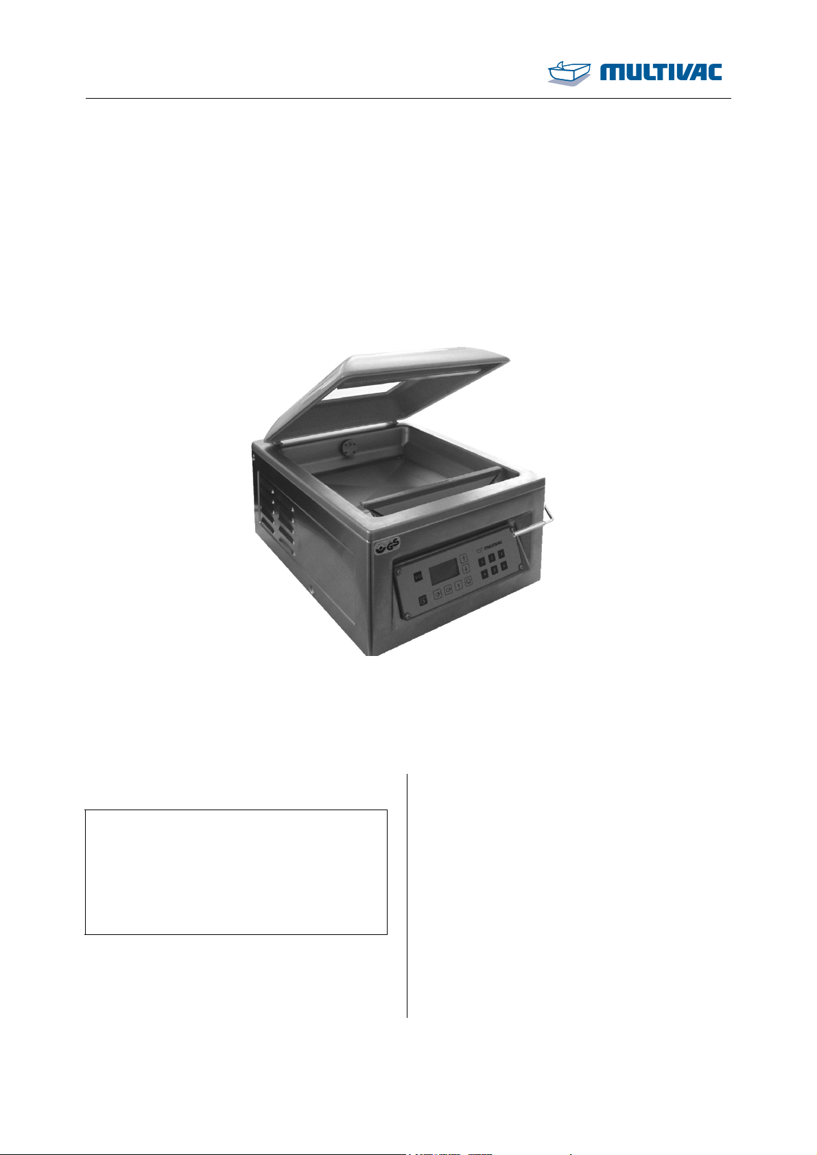
Instruction manual
Chamber machine C70
MC06
Serial number:
.........................................................
Service address: Manufacturer:
MULTIVAC
Sepp Haggenmüller GmbH & Co. KG
Bahnhofstraße 4
D-87787 Wolfertschwenden, Germany
Tel.: 0049 8334 601 0
www.multivac.com
Date: 11.06.2014
The reproduction, distribution and utilization of this document as well as the communication of its contents to others without express authorization is
prohibited. Offenders will be held liable for the payment of damages. All rights reserved in the event of the grant of a patent, utility model or design.
Language: English (EN) - Original operating manual
Order number: C70-P-WO-0000027.14-EN-ER
Page 2

Contents
Contents
Important information on the manual ....................................................................................... 6
Machine documentation ...................................................................................................... 6
Changes not covered in the manual.................................................................................... 7
Symbols used...................................................................................................................... 7
1 Safety.................................................................................................................................. 9
1.1 General safety instructions......................................................................................... 9
1.1.1 Target group................................................................................................... 9
1.1.2 Unauthorised modifications and manufacture of spare parts....................... 11
1.2 EC Conformity.......................................................................................................... 12
1.3 Intended use ............................................................................................................ 12
1.3.1 Electromagnetic compatibility (EMC) ........................................................... 13
1.3.2 Non-ionising radiation .................................................................................. 13
1.4 Reasonably foreseeable incorrect use..................................................................... 13
1.5 Warning against incorrect use.................................................................................. 13
1.6 Residual risks........................................................................................................... 14
1.7 Obligations of the operating company...................................................................... 14
1.7.1 Creating the operating directive................................................................... 14
1.7.2 Monitoring obligation.................................................................................... 14
1.7.3 Making the selection of personnel................................................................ 15
1.7.4 Training the personnel ................................................................................. 15
1.7.5 Providing personal protective equipment ..................................................... 15
1.7.6 Avoiding hazards.......................................................................................... 15
1.7.7 Providing the installation location................................................................. 15
1.7.8 Provide power supply................................................................................... 16
1.7.9 Observe the requirements for the gas supply.............................................. 16
1.7.10 Avoiding hygiene risks ................................................................................. 17
1.7.11 Checking the packs...................................................................................... 18
1.7.12 Pump protection function ............................................................................. 19
1.7.13 Testing pressure equipment......................................................................... 19
1.8 Safety devices.......................................................................................................... 19
1.8.1 Safety devices.............................................................................................. 20
1.9 Machine labels ......................................................................................................... 21
1.9.1 Safety labels and information labels ............................................................ 21
2 Description....................................................................................................................... 24
2.1 Design of the machine ............................................................................................. 24
2.1.1 Front view..................................................................................................... 24
2.1.2 Rear view..................................................................................................... 25
2.2 Control terminal........................................................................................................ 26
2.3 Display ..................................................................................................................... 27
2.3.1 Startup display ............................................................................................. 27
2.3.2 Status display............................................................................................... 28
2.3.3 Function display........................................................................................... 28
2.3.4 Diagnostic display ........................................................................................ 29
2 11.06.2014
Page 3

Contents
2.3.5
Access rights................................................................................................ 30
2.4 Menu tree ................................................................................................................. 31
2.5 Process sequence.................................................................................................... 31
2.6 Packaging process................................................................................................... 32
2.7 Preset recipes .......................................................................................................... 32
2.8 Technical data.......................................................................................................... 33
3 Start-up............................................................................................................................. 36
3.1 Initial start-up............................................................................................................ 36
3.1.1 Setting up the machine ................................................................................ 36
3.1.2 Adding oil to the vacuum pump.................................................................... 36
3.2 Connecting the power supply................................................................................... 37
3.3 Cleaning the machine (basic cleaning) .................................................................... 37
4 Operation ......................................................................................................................... 38
4.1 Switching on the machine ........................................................................................ 38
4.2 Switching off the machine ........................................................................................ 38
4.3 Packing products...................................................................................................... 39
4.4 Opening and closing menus..................................................................................... 41
4.4.1 Calling up menus ......................................................................................... 41
4.4.2 Quitting menus............................................................................................. 42
4.5 Changing values ...................................................................................................... 42
4.6 Selecting and resetting access rights....................................................................... 42
4.6.1 Selecting access authorisations................................................................... 42
4.6.2 Resetting the access right to operator (blocking access)............................. 42
4.6.3 Change password for authorisation access creator..................................... 43
4.6.4 To reset authorisation access creator.......................................................... 43
4.7 Language selection .................................................................................................. 43
4.7.1 Selecting the language via menu ................................................................. 43
4.7.2 Selecting the language via the shortcut key................................................. 43
4.8 Working with recipes ................................................................................................ 44
4.8.1 Load recipe .................................................................................................. 44
4.8.2 Load factory settings.................................................................................... 44
4.8.3 Save recipe.................................................................................................. 45
4.8.4 Delete recipe ................................................................................................ 45
4.9 Select and set process............................................................................................. 45
4.9.1 Set standard process................................................................................... 45
4.9.2 To set MCV process..................................................................................... 46
4.10 Setting the sealing.................................................................................................... 46
4.11 Entering basic settings............................................................................................. 46
4.12 Modifying and resetting machine cycles .................................................................. 46
4.13 Display production data............................................................................................ 47
4.13.1 Display total cycles of the machine .............................................................. 47
4.13.2 Display hours of operation ........................................................................... 47
4.13.3 Display cycle time ........................................................................................ 47
4.13.4 Show settings............................................................................................... 47
11.06.2014 3
Page 4

Contents
4.14
Setting the brightness of the display ........................................................................ 48
5 Cleaning ........................................................................................................................... 49
5.1 Notes on cleaning .................................................................................................... 49
5.1.1 Rules of conduct .......................................................................................... 49
5.1.2 Creating a company cleaning directive ........................................................ 49
5.1.3 Measures for ensuring a long service life..................................................... 49
5.1.4 Parameters for pre-rinsing and after-rinsing water....................................... 50
5.1.5 Handling cleansers....................................................................................... 50
5.1.6 Use with disinfectant.................................................................................... 51
5.1.7 Corrosion protection and lubrication ............................................................ 52
5.1.8 Cleaning devices.......................................................................................... 52
5.2 Cleaning the machine .............................................................................................. 53
5.2.1 Performing daily cleaning............................................................................. 53
5.2.2 Performing intensive cleaning ...................................................................... 58
5.3 Care products table.................................................................................................. 60
6 Maintenance.....................................................................................................................62
6.1 Maintenance schedule ............................................................................................. 62
6.2 Recommended maintenance ................................................................................... 63
6.2.1 Vacuum pump. - Perform the pump protection function............................... 63
6.2.2 Entire machine - Visual inspection............................................................... 63
6.2.3 Entire machine - Alkaline cleaning and disinfection..................................... 63
6.2.4 Entire machine - Wipe test ........................................................................... 64
6.2.5 Entire machine - Acidic cleaning and disinfection ........................................ 64
6.2.6 Entire machine - Intensive cleaning............................................................. 64
6.2.7 Chamber lid viewing window - Visual inspection.......................................... 64
6.2.8 Chamber lid gasket - Visual inspection ........................................................ 64
6.2.9 Sealing bar - Visual inspection..................................................................... 64
6.2.10 Connections - Visual inspection ................................................................... 64
6.2.11 Vacuum pump. - Checking oil level, refilling ................................................ 65
6.2.12 Vacuum pump. - Oil change......................................................................... 65
6.2.13 Vacuum pump. - Exchanging the air de-oiling element................................ 65
6.2.14 Vacuum system - Check .............................................................................. 65
6.3 Performing the vacuum test ..................................................................................... 65
6.4 Replace the sealing bar ........................................................................................... 66
6.4.1 Remove the sealing bar............................................................................... 66
6.4.2 Install the sealing bar ................................................................................... 66
6.5 Change the oil in the vacuum pump......................................................................... 67
6.5.1 Drain oil........................................................................................................ 67
6.5.2 Adding oil to the vacuum pump.................................................................... 68
7 Troubleshooting .............................................................................................................. 72
7.1 Malfunctions with diagnostic message..................................................................... 72
7.2 Malfunctions without diagnostic message................................................................ 73
8 Shutdown, transport, storage ........................................................................................ 75
8.1 Shutting down the machine...................................................................................... 75
8.1.1 Cleaning the machine .................................................................................. 75
4 11.06.2014
Page 5

Contents
8.1.2
Preserving the machine ............................................................................... 75
8.1.3 Closing and disconnecting supply lines ....................................................... 75
8.2 Transporting the machine ........................................................................................ 75
8.2.1 Transporting the machine ............................................................................ 75
8.3 Storing the machine ................................................................................................. 76
9 Disposal ........................................................................................................................... 77
9.1 Disposing of the machine......................................................................................... 77
9.2 Dispose of operating materials................................................................................. 77
9.2.1 Disposing of oil and grease.......................................................................... 77
9.2.2 Disposing of packaging materials ................................................................ 78
9.2.3 Dispose of chemicals................................................................................... 78
10 Spare parts....................................................................................................................... 80
Glossary .................................................................................................................................... 82
Index .......................................................................................................................................... 85
MULTIVAC branch offices........................................................................................................ 88
11.06.2014 5
Page 6
Important information on the manual
Important information on the manual
Read the manual carefully before you begin working with the machine.
• This manual is an integral component of the unit. Keep the manual
for future reference.
• Do not work with the machine until you have read through the
manual and completely understood its contents.
• Please contact MULTIVAC as soon as possible if there is something you do not understand in the manual! Your comments will
help us to further improve the manual.
• Do not start up the machine if there are any visible defects!
• Only trained persons are permitted to install, operate and service
the machine. The operating company is responsible for the qualifications and training of operating personnel.
• If you sell, transfer ownership or lend the machine to others, you
must provide the manual along with it!
For reasons of clarity, some illustrations show the machine without
the prescribed safety devices. Operating the machine without the
safety devices is prohibited.
WARNING
Injury hazard!
Altered, damaged, defective or incorrectly applied or missing safety
devices will render the danger zones unprotected.
Unprotected danger zones can cause serious or even fatal injuries.
¾ Do NOT alter the safety devices.
¾ Use only MULTIVAC spare parts and accessories.
Before switching on the machine each time:
¾ Check that all safety guards close completely and prevent
reaching into the danger zones.
¾ Check that only those safety devices are used which are suit-
able for the machine equipment.
¾ Check that all safety devices are functional and in a technically
flawless condition.
Machine documentation
• Instruction manual.
• EU Declaration of Conformity
• Supplementary sheet "Super-PIN" (loose page enclosed with the
machine).
Info
The complete scope of delivery is listed in the order confirmation.
6 11.06.2014
Page 7
Important information on the manual
Changes not covered in the manual
Changes not covered in the manual
Continuous development is the foundation for ensuring that our machines are technically advanced and of high quality. For this reason,
you may discover slight deviations between the specifications in the
manual and your machine. We also cannot rule out errors. The specifications, figures and descriptions in this manual do not constitute a
legal contract between the manufacturer and customer.
Symbols used
Warnings draw your attention to hazards. Warnings are displayed in
the following form:
Danger from electrical shock!
Used to indicate that serious danger of electrical shock is imminent.
DANGER
Ignoring this danger can cause serious or even fatal injuries.
¾ Observe the notices for avoiding danger.
Immediate danger!
Used to indicate that serious danger is imminent.
DANGER
Ignoring this danger can cause serious or even fatal injuries.
¾ Observe the notices for avoiding danger.
Dangerous situations!
Used to indicate dangerous situations.
WARNING
Non-observance can cause serious or even fatal injuries.
¾ Observe the notices for avoiding danger.
Potentially dangerous situations!
Used to indicate potentially dangerous situations.
CAUTION
Ignoring this danger can cause injuries.
¾ Observe the notices for avoiding danger.
NOTICE Danger of material damage!
Used to indicate potentially dangerous situations.
Ignoring these situations can cause material damage.
¾ Observe the notices for avoiding danger.
Information that contributes to a better understanding of how the machine functions is shown in the following form:
Info
Indicates information on special features deserving your attention.
11.06.2014 7
Page 8

Important information on the manual
Symbols used
Instructions to follow are displayed in the following form:
¾ Press key A.
¾ Release screw B.
¾ Press key C.
• Enumerated items are marked with bullet points.
– Dashes are used to mark sub-items of enumerated lists or se-
quences of steps to be taken.
8 11.06.2014
Page 9

Safety
1 Safety
1.1 General safety instructions
The machine incorporates the latest technological principles. Nevertheless, potential hazards for persons, the machine and other materials cannot be entirely excluded.
• Before you start up the machine, read through the instruction
manual and follow the instructions contained therein.
• Keep the instruction manual near the machine for future reference.
• Observe the safety and accident prevention regulations valid in
your country.
1.1.1 Target group
The persons, who work with or at the machine, must have as a minimum requirement the following capabilities, knowledge and competence:
• The persons are authorized by the company operating the machine to carry out those tasks, which they perform with or at the
machine.
• The persons are at least 14 years old.
• The persons know the danger zones of the machine and the accident prevention regulations.
• The persons know how they should behave in an emergency
situation.
• The persons have been given instruction about the machine and
are familiar with the handling of it.
• The persons have read and understood the operating directive.
• The persons have read and understood the instruction manual of
the machine.
• The persons have been informed about the possible hygiene risks.
The persons, who put the machine into service, or adjust and set it up,
or who are responsible for maintenance work and eliminating faults,
must have the following capabilities, knowledge and competence:
• Due to their professional training, knowledge and experience, as
well as their familiarity with the relevant regulations, the persons
are able to assess the tasks assigned to them and to recognize
potential hazards.
• The persons can read and interpret technical texts and technical
drawings or plans.
• The persons are familiar with the handling of computer-controlled
machines.
• The persons can install components and modules for technically
complex systems.
11.06.2014 9
Page 10

Safety
General safety instructions
• The persons can ensure that the machine remains capable of operation.
• The persons can perform maintenance work and inspections.
The persons, who carry out work on electrical components, must
have as a minimum requirement the following capabilities, knowledge
and competence:
• Due to their professional training, knowledge and experience, as
well as their familiarity with the relevant regulations, the persons
are able to assess the tasks assigned to them and to recognize
potential hazards.
• The persons have been trained as qualified electricians and are
able to prove this.
• The persons have up-to-date knowledge and experience in the
electrical area, and they have actively practised these skills in recent years.
The persons, who carry out work on gas supplies, must have as a
minimum requirement the following capabilities, knowledge and competence:
• Due to their professional training, knowledge and experience, as
well as their familiarity with the relevant regulations, the persons
are able to assess the tasks assigned to them and to recognize
potential hazards.
• The persons have been trained in handling gas supplies and are
able to prove this.
• The persons have up-to-date knowledge and experience in gas
supplies, and they have actively practised these skills in recent
years.
Injury hazard!
Operating the machine in a negligent and inattentive manner is very
WARNING
dangerous.
Negligent handling, inattentiveness and a disorderly work area can
cause serious injuries.
¾ Do NOT operate the machine if you are tired or under the influ-
ence of alcohol or medication.
¾ Work attentively and with care.
¾ Wear personal protective equipment.
¾ Keep the work area clean and orderly.
¾ Only carry out work for which training has been given.
10 11.06.2014
Page 11
Safety
General safety instructions
NOTICE Danger of material damage!
Improper use of the machine can damage it.
Damage can cause faults in the machine, which in turn can result in
reject packs.
¾ Do NOT overload the machine.
¾ Clean and service the machine on a regular basis.
¾ Check if the machine is in full working order prior to starting
work.
¾ Do NOT start the machine if you notice defects, damage or a
change in the operating behaviour of the machine.
¾ Have faults and damage repaired immediately by an authorised
technician.
¾ Repairs and service work should only be carried out by an
authorised technician.
1.1.2 Unauthorised modifications and manufacture of
spare parts
WARNING
Genuine MULTIVAC spare parts and accessories provide the highest
level of safety for personnel. Parts and equipment from other manufacturers have not been tested by MULTIVAC and are therefore not
approved. The use of such components can alter the properties of the
machine and thereby impair safe operation.
Injury hazard!
It is very dangerous to use third-party parts.
The use of third-party parts endangers safe operation and can
cause serious injuries.
¾ Do NOT perform any unauthorised modifications or conver-
sions.
¾ Do NOT modify or remove any protective or safety devices.
¾ Use only MULTIVAC spare parts and accessories.
The manufacturer disclaims any liability for damage caused by the
use of third-party parts or unauthorised modifications.
Fig. 1: Pro Original
The lubricants recommended by MULTIVAC are ideally matched to
the individual modules of the machine.
11.06.2014 11
Page 12

Safety
General safety instructions
NOTICE Danger of material damage!
The use of unsuitable lubricants can increase the wear of the machine and lead to corrosion of the transport chains.
This can damage the machine.
¾ Only use recommended lubricants for the transport chains.
1.2 EC Conformity
In the design and construction of packaging lines, packaging machines or auxiliary packaging machines, the following regulations
have been observed:
• EC Machinery Directive 2006/42/EC.
• EC Electromagnetic Compatibility Directive 2004/108/EEC (exception: industrial trucks such as lift trucks and die changing trolleys).
• Regulation 1935/2004/EC on materials and articles intended to
come into contact with food.
The safety objectives of the EC Low Voltage Directive 2006/95/EC
are complied with in accordance with point 1.5.1 of Annex I to the EC
Machinery Directive 2006/42/EC (exception: industrial trucks such as
lift trucks and die changing trolleys).
Agent authorised to compile the relevant technical documentation
according to Directive 2006/42/EC:
MULTIVAC Sepp Haggenmüller GmbH & Co. KG
Department of Technical Services
Bahnhofstraße 4
87787 Wolfertschwenden, Germany
Manufacturer:
MULTIVAC Sepp Haggenmüller GmbH & Co. KG
Bahnhofstraße 4
87787 Wolfertschwenden, Germany
Managing Director:
H.-J. Boekstegers
1.3 Intended use
The machine is a piece of technical equipment to be used exclusively
as a working appliance. The machine may only be operated by persons older than 14 years of age.
Use the machine only to pack products in pre-made film pouches.
The film pouches are closed with a seal seam.
For specifications, see Technical specifications.
12 11.06.2014
Page 13
Safety
Intended use
Any other use is considered improper and can endanger persons, the
product and the machine.
1.3.1 Electromagnetic compatibility (EMC)
The machine has been designed for use in residential, business and
industrial areas (without a separate power substation, it can be connected directly to the public mains). Operation can be impaired when
used in an industrial environment.
1.3.2 Non-ionising radiation
The machine produces unintended non-ionising radiation. This is only
emitted by electrical operating equipment as a function of its inherent
technical nature. e.g. from electric motors, high voltage wires, magnetic coils. There are moreover no strong permanent magnets built
into the machine. Any effect on active implants can therefore be excluded with a high degree of probability as long as a safety distance
of 30 cm is maintained between the implant and the field source. Active implants can be: heart pacemakers, defibrillators etc.
1.4 Reasonably foreseeable incorrect use
The following work methods are not in accordance with regulations
and therefore are prohibited:
• Operation in an atmosphere capable of explosion.
• Packing of highly flammable, combustible or explosion-prone
products.
• Packing of dust-forming or powder-forming material.
• Gas flushing of the packs.
• Use of the chamber lid and the viewing window in the chamber lid
as a storage, working or cutting surface.
• Cleaning of the chamber lid and the viewing window in the chamber lid with cleaning agents which have an abrasive effect (e.g.
abrasive household liquid cleaner, scouring pads, steel wool etc).
• Aseptic packing of products.
Info
Misuse will exclude any liability on behalf of the manufacturer. In
such a case, the operating company alone bears the risk.
1.5 Warning against incorrect use
• Incorrect operation
For example: sealing times that are too short or too long and therefore result in improperly sealed packs which in turn damage the
product.
• Neglecting the following work tasks:
– Inspections.
11.06.2014 13
Page 14

Safety
Warning against incorrect use
– Cleaning work.
– Maintenance work.
• Use of third-party parts, i.e. parts that are not MULTIVAC spare
parts.
• Operation under prohibited ambient conditions.
1.6 Residual risks
The safety instructions in this manual serve as guidelines for trained
operating personnel in safe working practice with the machine. The
manufacturer cannot however foresee all possible product-related
hazards. This is why the safety instructions and warnings on the machine and in this manual cannot be considered exhaustive. The operating company and operating personnel remain ultimately responsible
for safety.
1.7 Obligations of the operating company
1.7.1 Creating the operating directive
The machine and operating materials are a potential source of hazards. The operating company is obliged to draw up an operating directive. The operating directive regulates the handling of hazardous
machines or operating materials, as well as laying down rules for behaviour in the case of an emergency. The required information can be
found in the following documents:
• The EC directives for worker protection.
• National legislation.
• Accident prevention regulations.
• The machine instruction manual.
1.7.2 Monitoring obligation
The operating company is obliged to continuously monitor the condition of the entire machine, for example:
• Visible defects or damage.
• Changes in the operating behaviour.
• Age of the machine.
The operating company is obliged to ensure, that the machine is no
longer operated when it is older than 19 years. The correct functioning of the safety functions for the electronic components can no
longer be guaranteed after this age. The year of manufacture on the
type plate of the machine serves as the starting point for assessing
the age. In order to be able to operate the machine after this, the operating company must commission the manufacturer to check the
safety functions of the machine.
14 11.06.2014
Page 15
Safety
Obligations of the operating company
Info
Do NOT start up the machine, if there are visible defects or if the
machine is older than 19 years.
1.7.3 Making the selection of personnel
The operating company has to choose the personnel according to the
tasks to be carried out, see Section 1.1.1 "T
ARGET GROUP". The oper-
ating company has to order and authorise the personnel for the tasks
to be carried out.
Info
Trainees or other persons receiving instructions may only operate
the unit under the constant supervision of an experienced technician.
1.7.4 Training the personnel
The operating company is responsible for ensuring, that the personnel is trained and instructed in accordance with the tasks, which have
been assigned to them. The following measures can for example contribute to the training and instruction:
• Provide an operating directive, which is comprehensible to the
personnel.
• Instruct personnel on how to handle the machine correctly.
• Make the machine instruction manual accessible to the personnel.
If necessary, order an instruction manual from the manufacturer in
the appropriate official language.
• Inform the personnel about measures for avoiding hygiene risks.
• MULTIVAC offers appropriate training courses.
1.7.5 Providing personal protective equipment
The operating company must ensure that the operators wear the required personal protective equipment (foot protection, head gear,
gloves, etc.) in accordance with the national directives which apply. In
Europe the directive 89/656/EEC specifies the minimum mandatory
requirements for the use of personal protective equipment.
1.7.6 Avoiding hazards
The operating company must check, whether there are special hazards during operation, e.g. through hazardous fumes. The operating
company must undertake measures to avoid or limit the hazards.
1.7.7 Providing the installation location
The operating company is obliged to provide a suitable installation
location for the machine. The requirements for the installation location
can be obtained from the manufacturer.
11.06.2014 15
Page 16
Safety
Obligations of the operating company
1.7.8 Provide power supply
Connect the machine to the mains electricity at an always easily accessible place. In the case of an emergency the machine must be
capable of being disconnected immediately from the mains electricity.
The power supply must be equipped as follows:
• Overcurrent protective device according to IEC 60204-1: 2005.
• Mains power breaker according to IEC 60204-1: 2005.
Connection via residual
current protective
device
If the machine is to be operated via a residual current protective device, a residual current protective device which is sensitive to all types
of current should be used.
Info
In exceptional cases, the leakage current can be so high that an
isolating transformer needs to be installed between the power supply and the machine.
Connection to IT
network
General requirements
The machine cannot be connected directly to an IT network.
The IT network must be converted to a TN-S network by an isolating
transformer. The machine is connected to the TN-S network.
1.7.9 Observe the requirements for the gas supply
Info
Compliance with the following requirements is mandatory and is
one of the operating company's imperative obligations!
• The operating company is obliged to connect the gas supply in a
way that poses no danger to employees or third parties.
• The operating company is obliged to create an instruction manual
with all safety-related information for the following phases in the
service life of the machine:
– Starting up.
– Operation and conduct in the event of unusual occurrences.
– Servicing during operation.
– Shutdown.
– Rectification of faults.
• All parts of the gas supply and its equipment, which come into contact with oxidizing acting gases, are to be kept free of oil and
grease.
16 11.06.2014
Page 17

Personnel qualifications
Structural requirements
Safety
Obligations of the operating company
• The operating company must ensure that the input and operating
pressures given in the Technical specifications are adhered to and
not exceeded.
Only qualified persons with the corresponding required training, experience and reliability may perform work on the gas supply.
• The operating company is obliged to install a pressure reducer and
safety valve in the gas supply line to the machine.
• The operating company is obliged to connect the machine to the
gas supply with a lockable ball valve.
When the ball valve is closed, the supply of gas to the machine is
interrupted.
• It must be ensured that the input pressure at the machine does not
exceed that given in the Technical specifications, e.g. through the
fitting of an overpressure valve.
• The pressure relief capacity of the safety valve must be dimensioned for the maximum possible throughput of the pressure reducer.
• In the case of a release of pressure, the gas must be diverted to
non-hazardous areas.
1.7.10 Avoiding hygiene risks
A high standard of hygiene is achieved through design, choice of materials and workmanship.
It is imperative that this high level of hygiene be maintained by every
operating company. Particularly where food or sterile medical products are being packed, the currently valid hygiene standards must be
strictly observed. The person charged by the operating company with
safety and/or hygiene must clarify, which regulations apply to the
product to be packed, and the person must then implement these
regulations.
The manufacturer assumes no liability whatsoever for any warranty
claims and damage claims of any kind resulting from insufficient hygiene and insufficient cleaning.
11.06.2014 17
Page 18
Safety
Obligations of the operating company
Health hazard!
Insufficient or sporadic cleaning can promote the growth of micro-
WARNING
organisms which can change unfavourably the product that is to be
packed.
This can severely damage the health of people, especially of the
consumers.
Among other measures the following are definitely required:
¾ Create a company cleaning guideline.
¾ Perform cleaning regularly.
¾ Check the effectiveness of cleaning procedures on a regular
basis.
¾ Follow instructions in the chapter 'Cleaning'.
1.7.11 Checking the packs
Health hazard!
Faulty or damaged packs (reject packs) can have far-reaching con-
CAUTION
sequences, for example, spoiled products.
Spoiled products can pose a health hazard.
¾ Check packs on a regular basis during running operation.
¾ Do NOT put faulty or damaged packs (reject packs) into circula-
tion.
Info
It is the operating company's duty to determine the overall testing
procedure.
Testing procedure
Depending on the film pouch and the demands placed on the packs,
various types of testing procedures are available, e.g.:
• Check seal seam width.
• Visual inspection: Asses the pack optically.
• Storage test: Store a good pack for a defined period and then reinspect.
• Stacking test: Stack good packs on top of each other for a defined
period and then re-inspect.
• Check the seal seam strength with a tensile testing machine.
• Low-pressure test (for vacuum packs).
• Measurement residual oxygen (for gas-flushed packs).
The following faults can result in a pack not being airtight:
• A leaky seal seam. Possible reasons:
– The inside of the packaging material is contaminated by product
in the seal seam area.
– The sealing time is too short.
18 11.06.2014
Page 19

Time of inspection
Safety
Obligations of the operating company
• Damage to the pack caused e.g. by sharp-edged products.
• After machine start-up.
• When a defined time interval was reached during running operation.
• When the pack size was changed.
• When other types of films or other film thicknesses are being used.
• When spare parts or wearing parts were built in.
• After faults to the machine were eliminated.
• After changes to the machine settings.
1.7.12 Pump protection function
The vacuum pump in the machine runs for a set time when the
chamber lid has been closed. During this time any undesired liquid in
the oil of the vacuum pump evaporates. This increases the lifespan of
the vacuum pump. When packaging moist or liquid products, the operating company is obliged to perform this function at least once a
day at the end of a working day. The manufacturer assumes no liability whatsoever for any warranty claims and damage claims of any
kind that result from the insufficient performance of this function.
NOTICE Danger of material damage!
Penetration by foreign matter (e.g. liquids, product residue, foreign
bodies) will damage the vacuum pump.
Damage can cause faults in the machine, which in turn can result in
reject packs.
¾ Cancel the evacuation process immediately if foreign matter is
sucked in.
¾ Change the oil in the vacuum pump.
1.7.13 Testing pressure equipment
The operating company is responsible for observing the countryspecific test intervals for pressure equipment. This test is to be performed by qualified persons.
1.8 Safety devices
Safety devices on the machine:
11.06.2014 19
Page 20
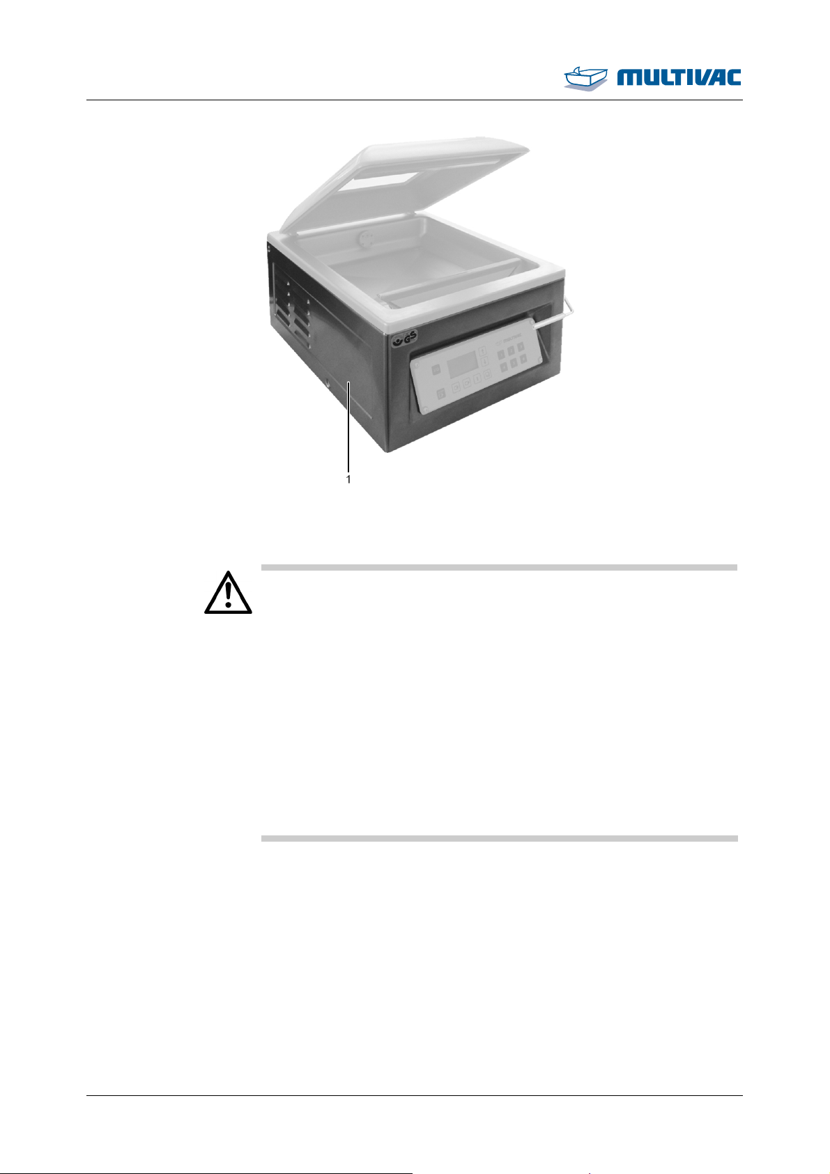
Safety
Safety devices
WARNING
Fig. 2: Safety devices
1
Protective device
Injury hazard!
Altered, damaged, defective or incorrectly applied or missing safety
devices will render the danger zones unprotected.
Unprotected danger zones can cause serious or even fatal injuries.
¾ Do NOT alter the safety devices.
¾ Use only MULTIVAC spare parts and accessories.
Before switching on the machine each time:
¾ Check that all safety guards close completely and prevent
reaching into the danger zones.
¾ Check that only those safety devices are used which are suit-
able for the machine equipment.
¾ Check that all safety devices are functional and in a technically
flawless condition.
1.8.1 Safety devices
Safety devices cover the danger zones lying beneath them. Depending on the equipment of the machine, various safety devices are used,
e.g. side panels, doors, protective plates, etc.
20 11.06.2014
Page 21
Safety
Safety devices
Injury hazard!
Missing protective devices result in unprotected danger zones.
WARNING
Reaching into unprotected danger zones can lead to serious or
even fatal injuries.
¾ Do NOT put the machine into operation without protective de-
vices.
¾ Check that all protective devices are attached and in a techni-
cally flawless condition.
¾ Check that all protective devices are completely closed without
gaps.
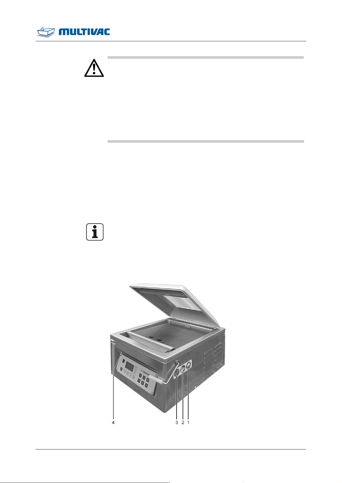
1.9 Machine labels
Safety and information labels have been attached to the machine.
• Do NOT remove these labels.
• Make sure all labels are intact and legible.
• If necessary, clean the labels with soap and water.
– Do NOT clean the labels with solvents.
• Replace damaged, scratched or illegible labels with new ones.
Front view
Info
Labels can be obtained from the manufacturer.
1.9.1 Safety labels and information labels
Fig. 3: Front view of the position of the labels
11.06.2014 21
Page 22
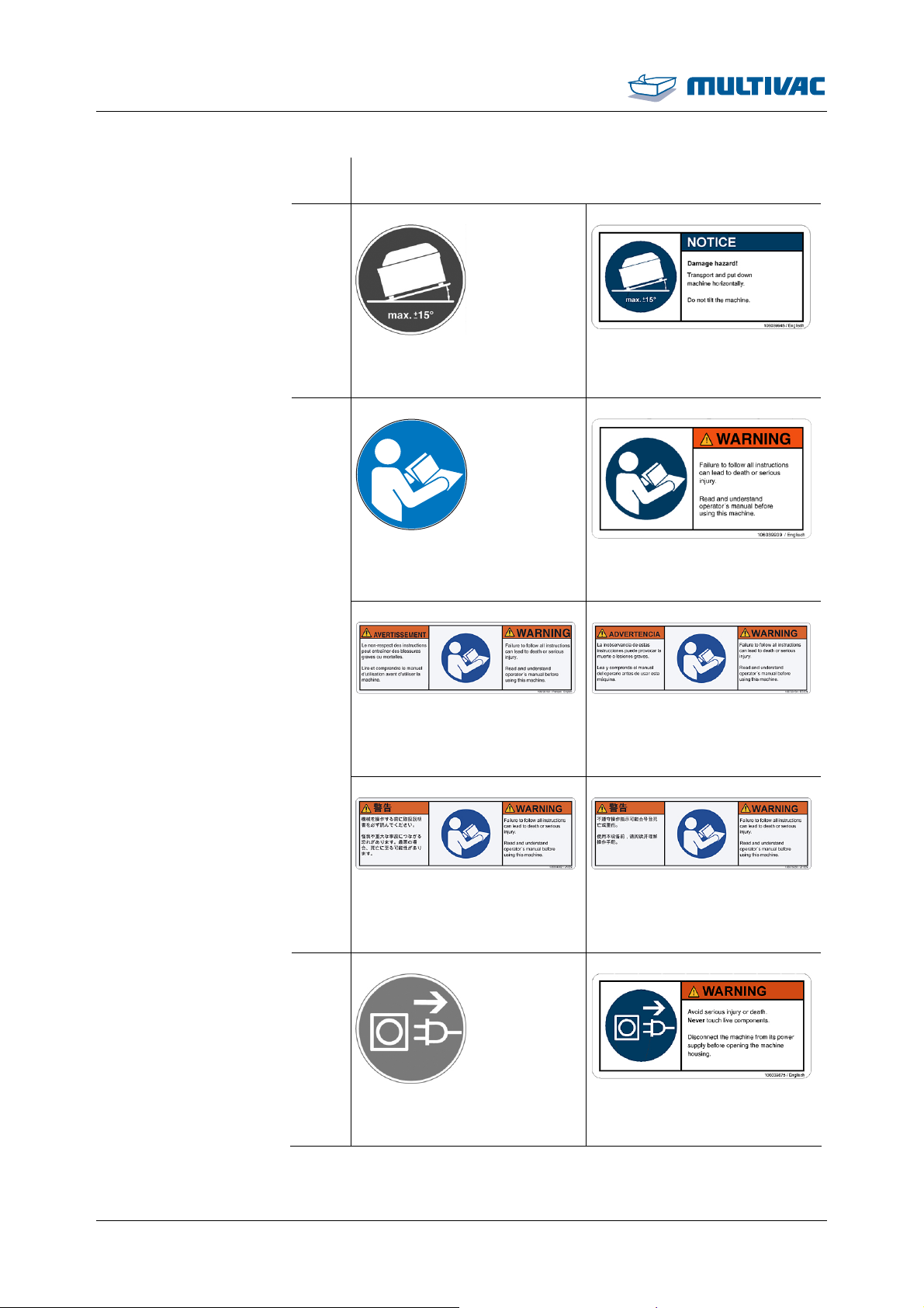
Safety
Machine labels
Position
1
Sign
2
Fig. 4: ISO mandatory sign: inclina-
tion of the machine
Fig. 6: ISO mandatory sign: Read the
instruction manual
Fig. 8: ANSI mandatory sign: Read
the instruction manual (English / French)
Fig. 5: ANSI mandatory sign: inclina-
tion of the machine
Fig. 7: ANSI mandatory sign: Read
the instruction manual
Fig. 9: ANSI mandatory sign: Read
the instruction manual (English / Span-
ish)
Fig. 10: ANSI mandatory sign: Read
the instruction manual (English / Japa-
nese)
Fig. 11: ANSI mandatory sign: Read
the instruction manual (English / Chi-
nese)
3
Fig. 12: ISO mandatory sign: unplug
the power plug
22 11.06.2014
Fig. 13: ANSI mandatory sign: unplug
the power plug
Page 23
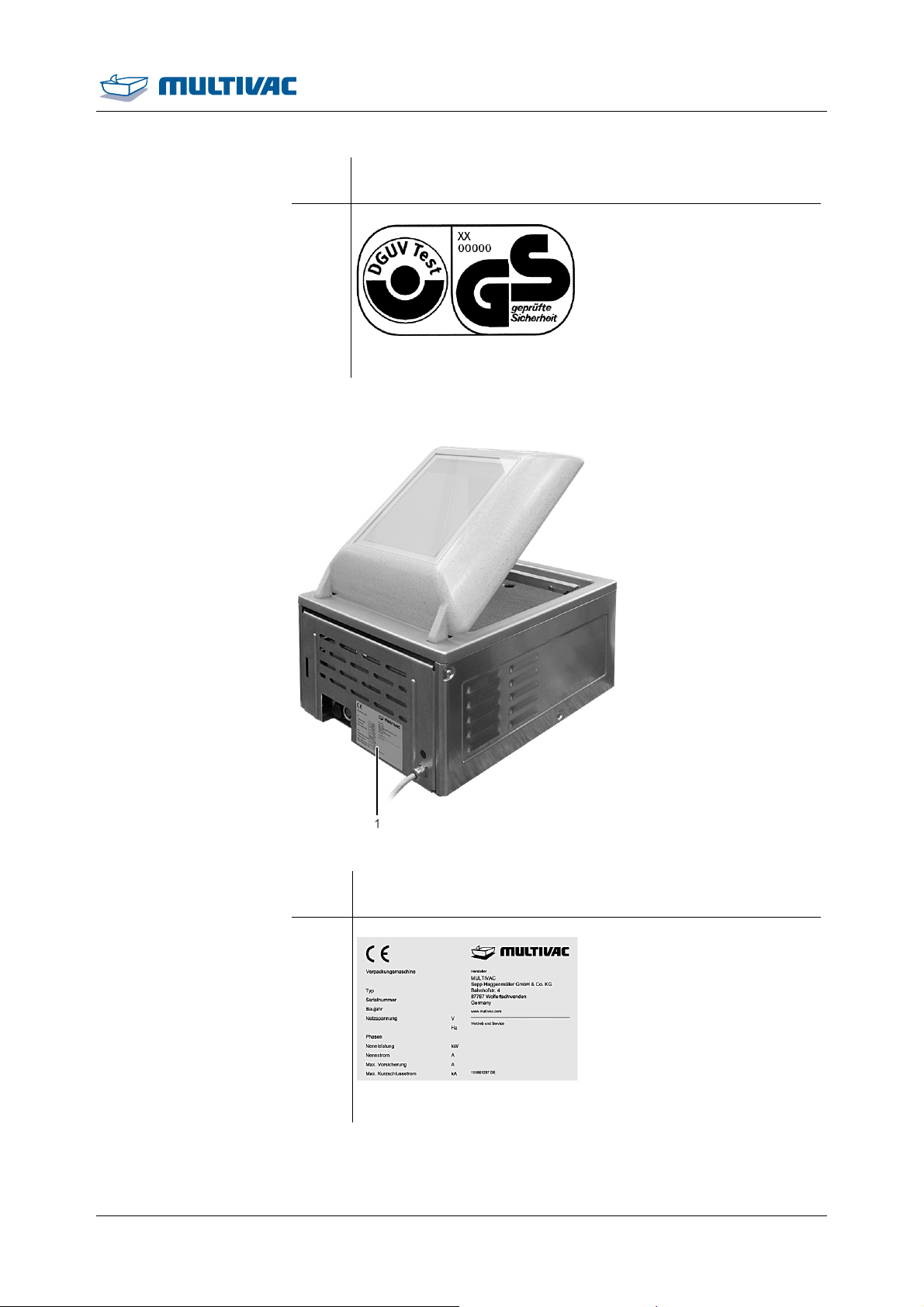
Rear view
Position
4
Safety
Machine labels
Sign
Fig. 14: GS mark
Fig. 15: Rear view of the position of the labels
Posi-
Sign
tion
1
Fig. 16: Type plate
11.06.2014 23
Page 24
Description
2 Description
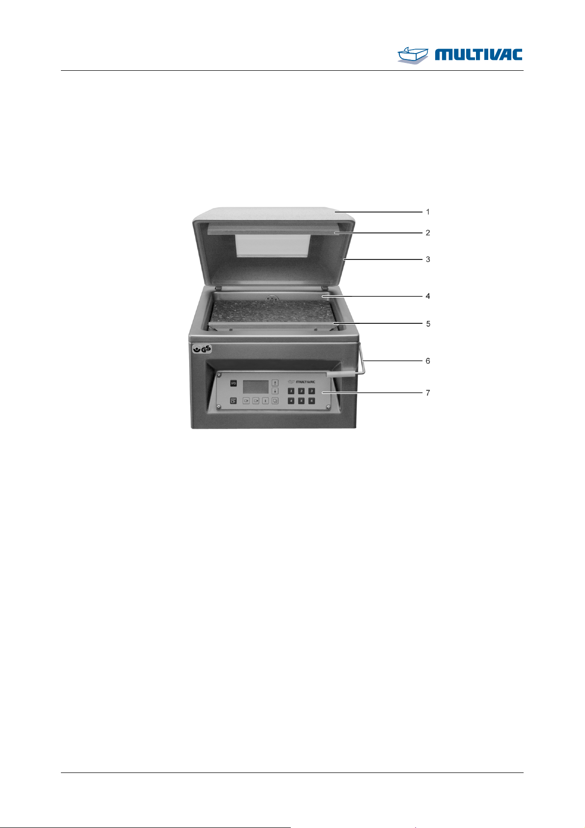
2.1 Design of the machine
2.1.1 Front view
Fig. 17: Front view
1
Chamber lid
2
Counter-pressure bar
3
Chamber lid gasket
4
Chamber
5
Sealing bar
6
Locking for lid
7
Control terminal
24 11.06.2014
Page 25
Description
Design of the machine
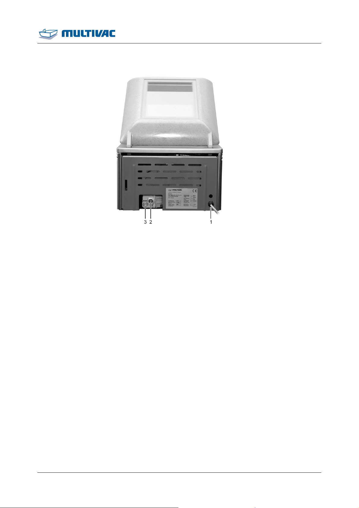
2.1.2 Rear view
Fig. 18: Rear view
1
Power supply connection
2
Oil sight glass
3
Screw plug of the drain opening
11.06.2014 25
Page 26
Description
Control terminal
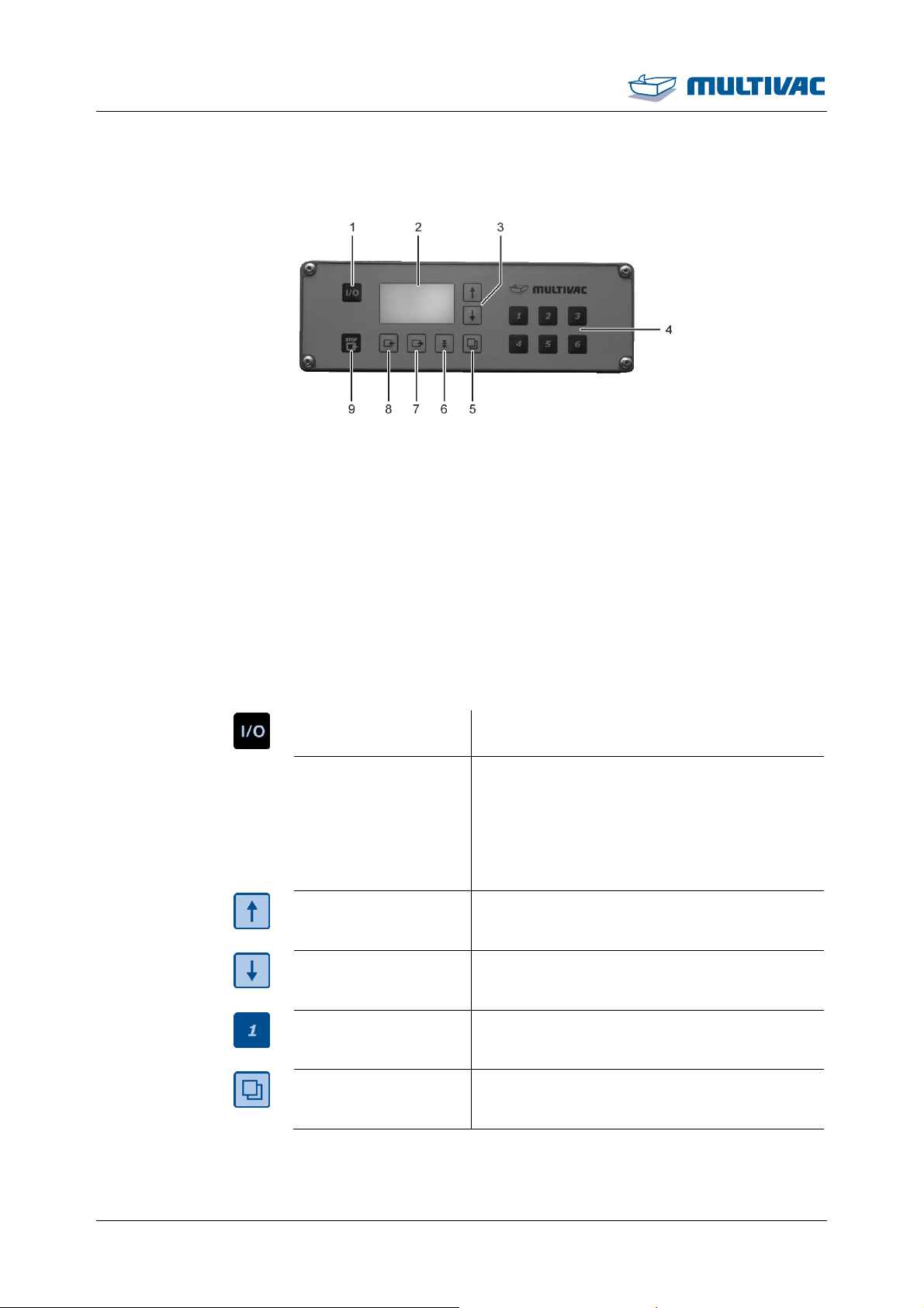
2.2 Control terminal
Fig. 19: Control terminal
1
Machine control key<Machine control On/Off>
2
Display
3
Keys <Arrow key>
4
Keys <1> to <6>
5
<Function selection> key
6
<Sealing> key
7
<Gas flushing> key
8
<Evacuation> key
9
<Stop> key
<Machine control
On/Off>
Display
<Arrow key>
<Arrow key>
Keys <1> to <6>
<Function selection>
• Switch machine control on and off.
• Display process data.
• Show menus.
• Show parameters and functions.
• Graphic support.
• Display diagnostic messages.
• Increase values.
• Navigation within menus.
• Decrease values.
• Navigation within menus.
• Load and save recipes.
• Enter password.
• Call up additional menus.
• Scroll to previous screen.
26 11.06.2014
Page 27
Description
Control terminal
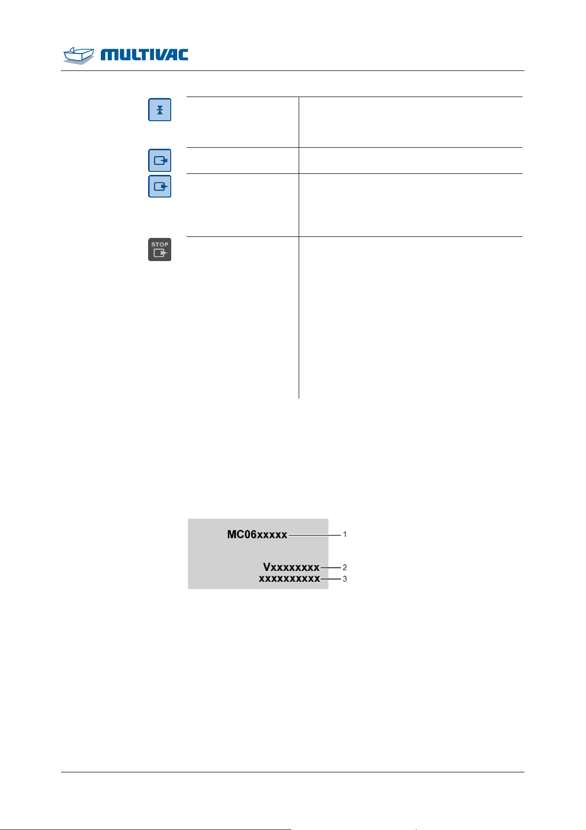
<Sealing> key
• Press and hold down: Call up "Sealing"
menu.
• Press briefly: Call up values for sealing.
<Gas flushing> key No function.
<Evacuation> key
• Press and hold down: Call up "Evacuation"
menu.
• Press briefly: Call up values for evacuation.
<Stop> key
• Skip current machine process and proceed
with the next process.
– Pressing during the evacuation process:
Aborts the evacuation process and resumes the sealing process.
– Press during sealing process: Cancel
sealing process and ventilate the
chamber.
• Acknowledge diagnostic message.
• Return from the menu to the status display.
2.3 Display
The display shows different views with differing information depending on the machine's phase of operation.
2.3.1 Startup display
The startup screen appears after switching on the machine.
Fig. 20: Startup display
1
Type designation of machine control
2
Software version
3
Configuration code
11.06.2014 27
Page 28
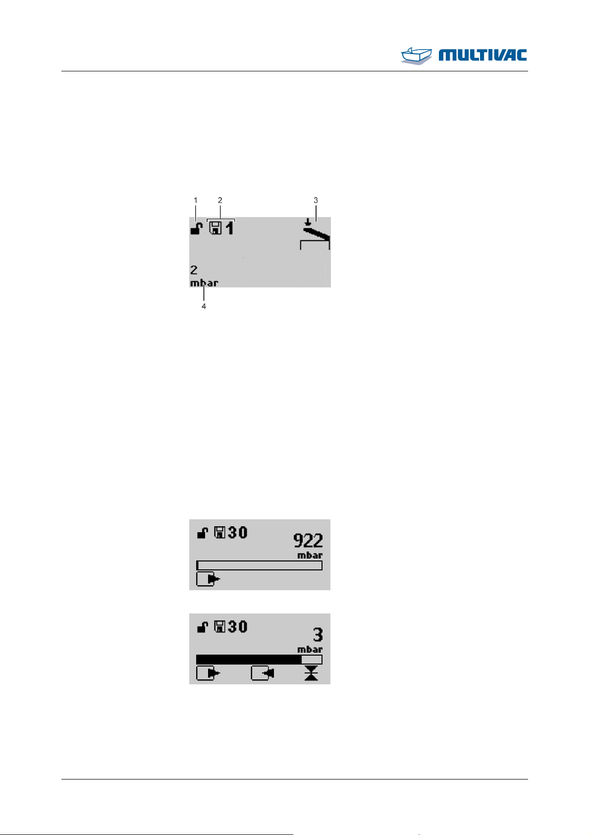
Description
Display
Process data status
display
2.3.2 Status display
The process data status display shows information on the last packaging procedure.
Fig. 21: Process data status display
Process sequence
status display
1
Current access right (lock closed = user; lock open = creator)
2
Currently loaded recipe
3
Chamber lid symbol, machine is ready.
4
Evacuation pressure
The process sequence status display shows the progress of a currently running process. During a packaging procedure process the
corresponding symbol flashes on the display. If time runs out during a
process, then a clock with the remaining time will flash in place of the
symbol.
Fig. 22: Evacuation status display (047)
Fig. 23: Sealing status display (050)
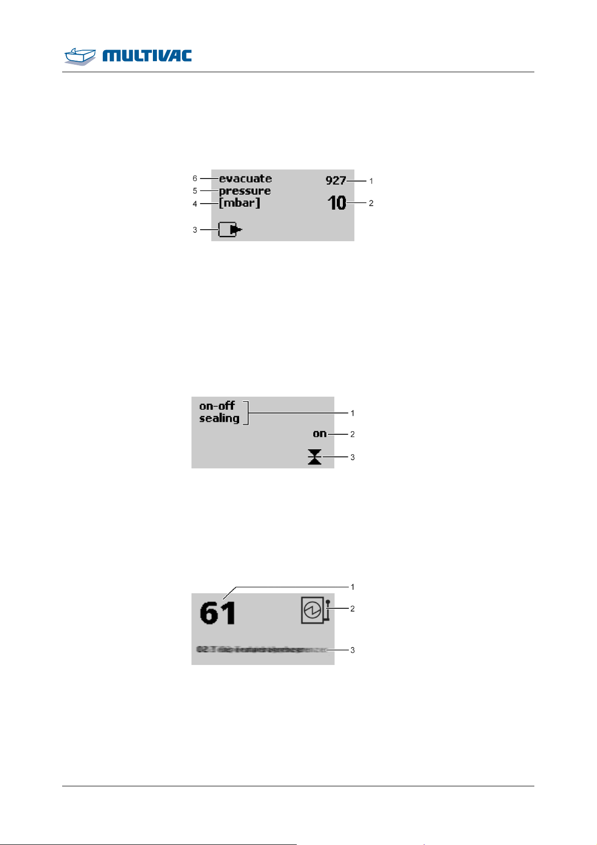
2.3.3 Function display
Depending on the access rights, the function display will offer the
following options:
28 11.06.2014
Page 29
Description
Display
• View values.
• Enter values.
• Switch functions on and off.
Example of a function display with values:
Fig. 24: Function display with value (052)
1
Actual value
2
Setting
3
Symbol of function (e.g. evacuation)
4
Measurement
5
Selected parameter
6
Selected function
Example of a function display for switching a function on and off:
Fig. 25: Function display on/off (013)
1
Selected function
2
Switch status
3
Symbol of function (e.g. sealing)
2.3.4 Diagnostic display
Fig. 26: Diagnostic display
1
Diagnostic number
2
Type of error acknowledgement
3
Error text (in ticker)
Eliminate the malfunction, see Section 7 "TROUBLESHOOTING".
11.06.2014 29
Page 30

Description
Display
2.3.5 Access rights
To avoid incorrect operation, the following access rights are assigned.
Access right Explanation
Operator Not password protected.
The operator may enter settings that are required to operate the machine (e.g. Language choice).
The operator cannot modify values.
Set-up personnel Password protected.
The set-up personnel can modify values and
switch statuses.
Only a limited number of settings in the service menu are possible (e.g. vacuum test).
Service Unrestricted authorisation.
Super-PIN
• Reset password for access right Set-up
personnel to factory setting.
• Reset machine control.
30 11.06.2014
Page 31
Description
Menu tree
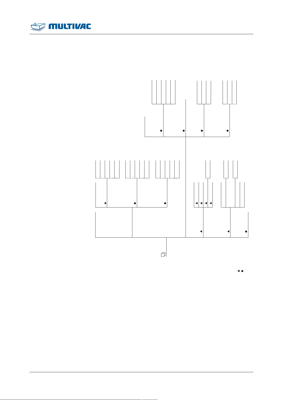
2.4 Menu tree
(Exit)
Distribution time
Automatic
Procedure (standard/MCV)
MCV threshold
MCV period
(Exit)
Sealing (On/Off)
Ventilation delay
Cool off
(Exit)-Fill diaphragm
Ventilate diaphragm
(Exit)
(Exit)
(Exit)
Recipe 1
Recipe 2
Recipe 3
Recipe n
Recipe 30 Factory settings
Load recipe
(Exit)
Recipe 1
Recipe 2
Save recipe
Recipe
(Exit)
Recipe 3
Recipe n
Recipe 30 Factory settings
(Exit)
Evacuate
Recipe 1
Recipe 2
Delete recipe
Menue
Gas flushing (not active)
Recipe 3
Recipe n
Recipe 30 Factory settings
Settings
(Exit)
Sealing
Change PIN
Language
Authorisation
User
Reset PIN
PIN
Brightness
Basic Settings
Machine cycles
Total cycles
(Exit)
Counter
Production data
Operating hours
Vacuum pump
Operating hours
Cycle period
Settings
Service
User
Configurator
Legend:
(Password: 1234)
Fig. 27: Menu tree
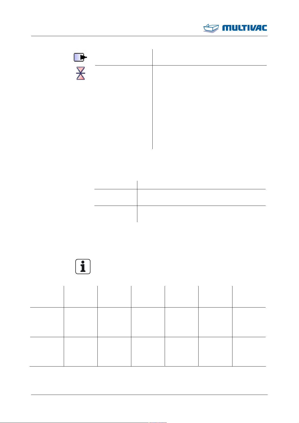
2.5 Process sequence
The film pouches are filled and laid in the chamber. When the chamber is closed, the following procedures run automatically:
11.06.2014 31
Page 32
Description
Process sequence
Evacuation Evacuation if chamber and film pouches.
Sealing
• Compressed air is admitted to the sealing
diaphragm. The sealing diaphragm expands, pressing the sealing bar against the
counter-pressure bar.
• The film pouch is sealed.
• The sealing bar and seal seam cool off.
• The sealing diaphragm is ventilated, the
sealing diaphragm slackens.
• The chamber is ventilated.
• The chamber lid opens automatically if it is
not locked
2.6 Packaging process
Recipe Example of
use
No. 1 For dry
products
without gas
flushing.
The following processes are available for packing products.
Processes Example of use
Standard Technical products or products without special
requirements.
MCV Testing airtightness of packs or for drying prod-
ucts.
2.7 Preset recipes
Recipes 1 to 6 are preset at the factory. The settings depend on the
machine equipment.
Info
Recipes 1 to 6 contain presettings which have to be adjusted to the
individual cases.
Evacuation
pressure
Automatic 4 Off 1.8 s Off
Automatic
sensitivity
Gas flushing pressure
Sealing
time
MHP
No. 2 For moist
Automatic 10 Off 1.8 s Off
products
without gas
flushing.
32 11.06.2014
Page 33
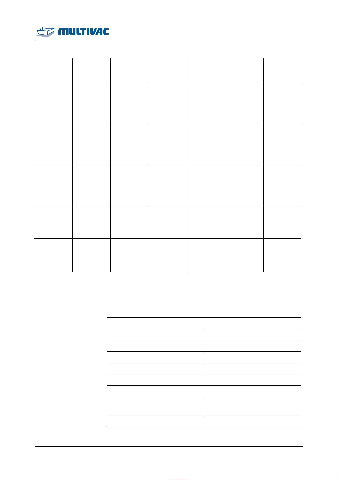
Recipe Example of
use
Evacuation
pressure
Automatic
sensitivity
Gas flushing pressure
Sealing
time
Description
Preset recipes
MHP
No. 3 For dry
products
with little
gas flushing.
No. 4 For dry
products
with medium gas
flushing.
No. 5 For dry
products
with strong
gas flushing.
No. 6 For prod-
ucts with a
big air
pocket.
No. 30 Factory
settings
Automatic 4 100 mbar to
1.8 s Off
150 mbar
Automatic 4 250 mbar 1.8 s Off
Automatic 4 500 mbar 1.8 s Off
12 mbar 10 Off 1.8 s Evacuation
time: 2 s
Evacuation
pause: 4 s
10 mbar 6 Off 1.3 s Evacuation
time: 2 s
Evacuation
pause: 2 s
2.8 Technical data
Power supply connection
Mains voltage See type plate.
Phases See type plate.
Nominal power See type plate.
Nominal current See type plate.
Max. pre-fuse See type plate.
Max. short-circuit current See type plate.
Protection type IP54
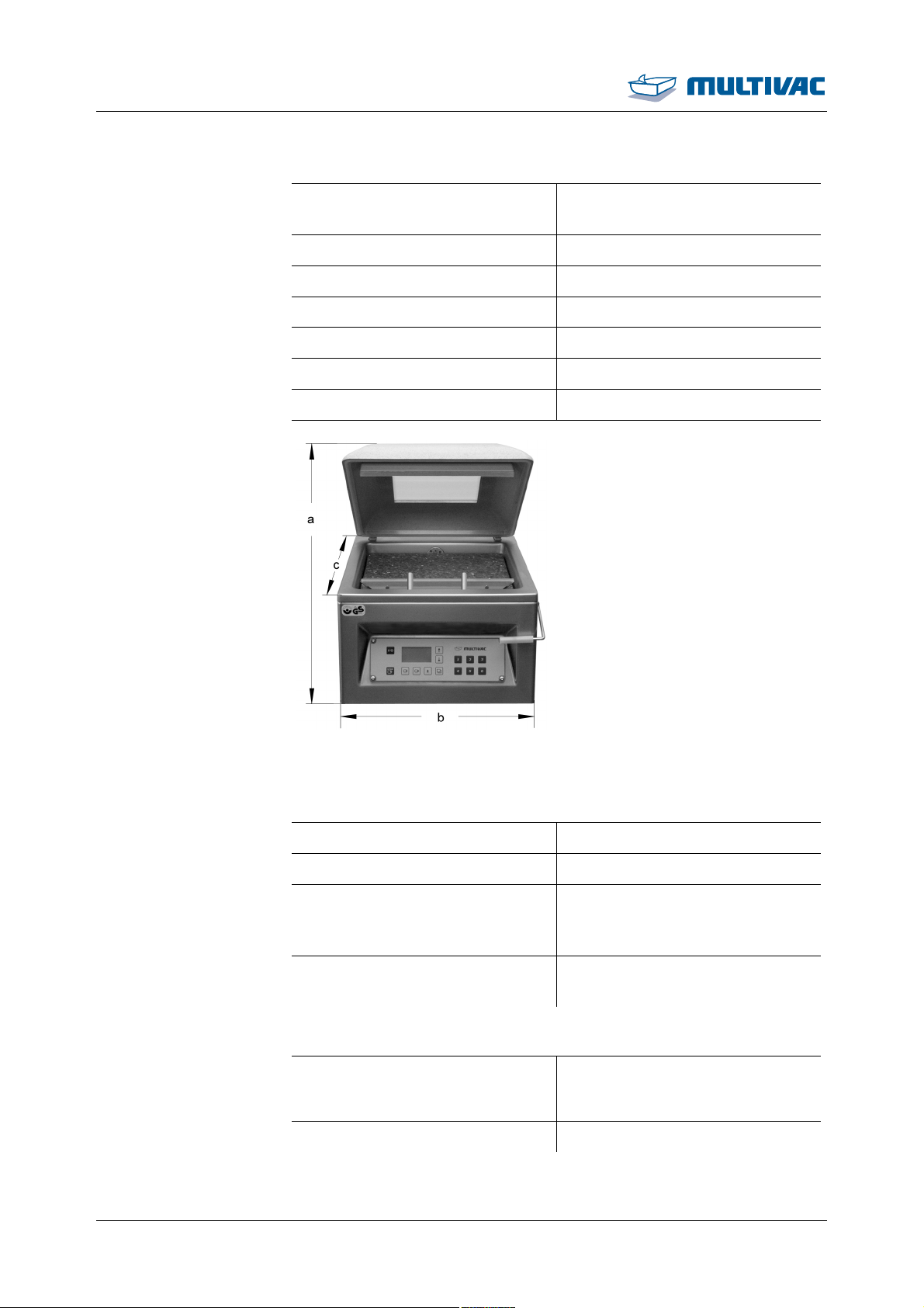
Dimensions
Height (a) with open chamber lid 550 mm
11.06.2014 33
Page 34
Description
Technical data
Dimensions
Height (a) with closed chamber
330 mm
lid
Width (b) 400 mm
Depth (c) 500 mm
Operating height approx. 256 mm
Effective chamber size (W/H/D) 310 mm/120 mm/310 mm
Sealing length 305 mm
Weight approx. 50 kg
Fig. 28: Dimensions
Installation conditions and ambient conditions
Ambient temperature +2 °C to +40 °C
Storage temperature -25 °C to +80 °C
Relative air humidity during op-
90 % non-condensing
eration or storage of the machine, max.
Inclination of the machine during
15 °
transport, max.
Vacuum pump.
Vacuum pump
• VP8: 8 m
3
/h
• R5 KB 0010D: 10 m
Achievable final pressure approx. 2 mbar
3
/h
34 11.06.2014
Page 35
Description
Technical data
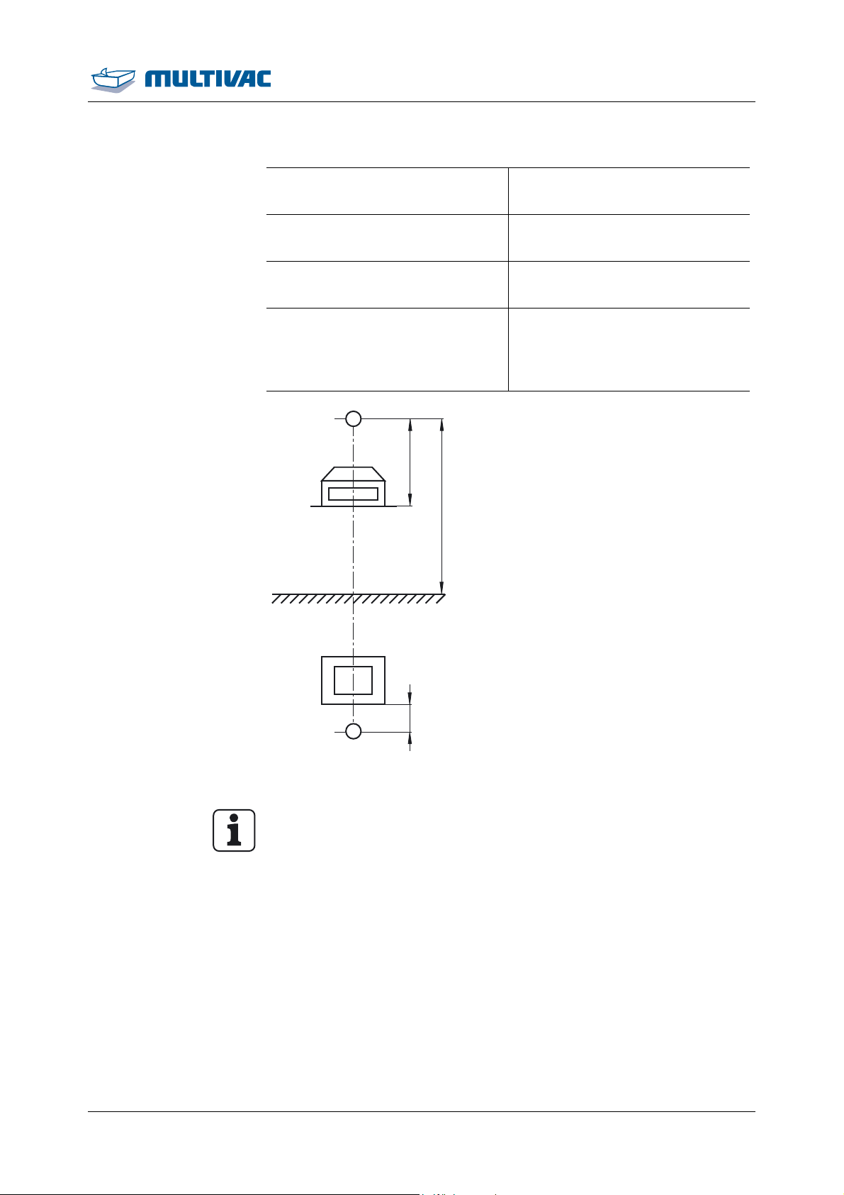
Noise exposure at workplace
Based on Machinery Directive
(2006/42/EG)
Measuring instrument Sound level meter, IEC 61672- 1,
class 1, fault limit +/-1,1 dB
Condition of the machine New condition with optimum set-
tings at the time of delivery.
A-weighted emission soundpressure level at the workplace
(DIN ISO 11204, accuracy
L
pA
class 3)
A
0,7 m
1,55 m
A
0,5 m
Fig. 29: Noise exposure measuring point
<70 dB
Info
The readings of the noise data have been adjusted to take extraneous and ambient noises into account.
Higher readings may be produced as a result of the following:
• Highly sound-reflecting rooms.
• Modified settings.
• Wear.
11.06.2014 35
Page 36
Start-up
3 Start-up
3.1 Initial start-up
3.1.1 Setting up the machine
¾ Prepare a firm, level site for the machine.
¾ Ensure there is adequate access to the connections at the desired
location.
¾ Observe the technical specifications.
Danger of explosion!
Operating the machine in a potentially explosive atmosphere can
DANGER
result in explosion due to hot machine parts.
Explosions can cause serious injuries or even death.
¾ Do NOT use the machine in rooms that are exposed to explo-
sion hazards.
NOTICE Danger of material damage!
At an inclination of more than 15°, the oil in the vacuum pump
shifts.
The air de-oiling elements will get wet from the oil and become ineffective. This will damage the vacuum pump.
¾ Transport and set the machine down as horizontally as possi-
ble.
¾ Do NOT tilt the machine.
¾ Transport the machine to the desired location, see Section 8.2.1
"TRANSPORTING THE MACHINE ".
¾ Set up the machine on a firm, level base.
3.1.2 Adding oil to the vacuum pump
36 11.06.2014
¾ Fill oil into the vacuum pump, see Section 6.5.2 "ADDING OIL TO
THE VACUUM PUMP".
Page 37
Start-up
Connecting the power supply
3.2 Connecting the power supply
NOTICE Danger of material damage!
If the mains voltage of the machine does not match that of the
mains, the machine will be overloaded.
This can damage the vacuum pump.
¾ Connect the machine to the mains electricity only if the voltages
are identical.
¾ Check the mains voltage on the type plate and compare it with the
voltage of the mains electricity.
¾ If the values match, connect the machine to the mains electricity
in an always easily accessible place.
3.3 Cleaning the machine (basic cleaning)
¾ After putting the machine into service carry out an intensive clean-
ing of the machine, see Section 5 "CLEANING".
Info
The machine is only to be used for production after a basic cleaning.
11.06.2014 37
Page 38
Operation
4 Operation
4.1 Switching on the machine
¾ Before switching on the machine for the first time fill the vacuum
pump with oil, see Section 6 "MAINTENANCE".
¾ If present, open the stop-cock for the gas supply.
¾ Connect the machine to the mains electricity at a place which is
always easily accessible.
¾ Press the <Control On/Off> key.
– The machine control performs a self-test.
– The software version of the machine control briefly appears in
the display.
– The status display appears.
– The machine is ready for operation.
4.2 Switching off the machine
¾ Press the <Control On/Off> key.
– The screen for performing the pump protection function ap-
pears.
¾ If necessary, perform the pump protection function.
¾ Close and press down the chamber lid.
– The vacuum pump runs for a set time.
– A counter counts to zero.
– The display goes out.
– The chamber lid opens automatically if it is not locked.
¾ To cancel the pump protection function, press the <Control
On/Off> key again.
– The display goes out.
Info
The display goes out automatically after 10 s without input or without closing the chamber lid.
¾ Close chamber lid and lock it in place.
¾ Close the stop valve for the gas supply, if part of the machine.
¾ If required disconnect the machine from the mains electricity.
38 11.06.2014
Page 39
Operation
Packing products
4.3 Packing products
¾ Switch on the machine.
¾ Load the desired recipe.
¾ For the first test packs, use a preset recipe, see Section 2.7
"PRESET RECIPES " and see Section 4.8.2 "LOAD FACTORY SET-
TINGS ".
Health hazard!
Insufficient or sporadic cleaning can promote the growth of micro-
WARNING
organisms which can contaminate the product.
This can pose serious health hazards for consumers.
¾ Disinfect your hands should they come into contact with any
machine part other than the operating elements.
¾ Do NOT lay the product on the machine.
¾ Observe the company cleaning guidelines.
¾ Follow instructions in the chapter 'Cleaning'.
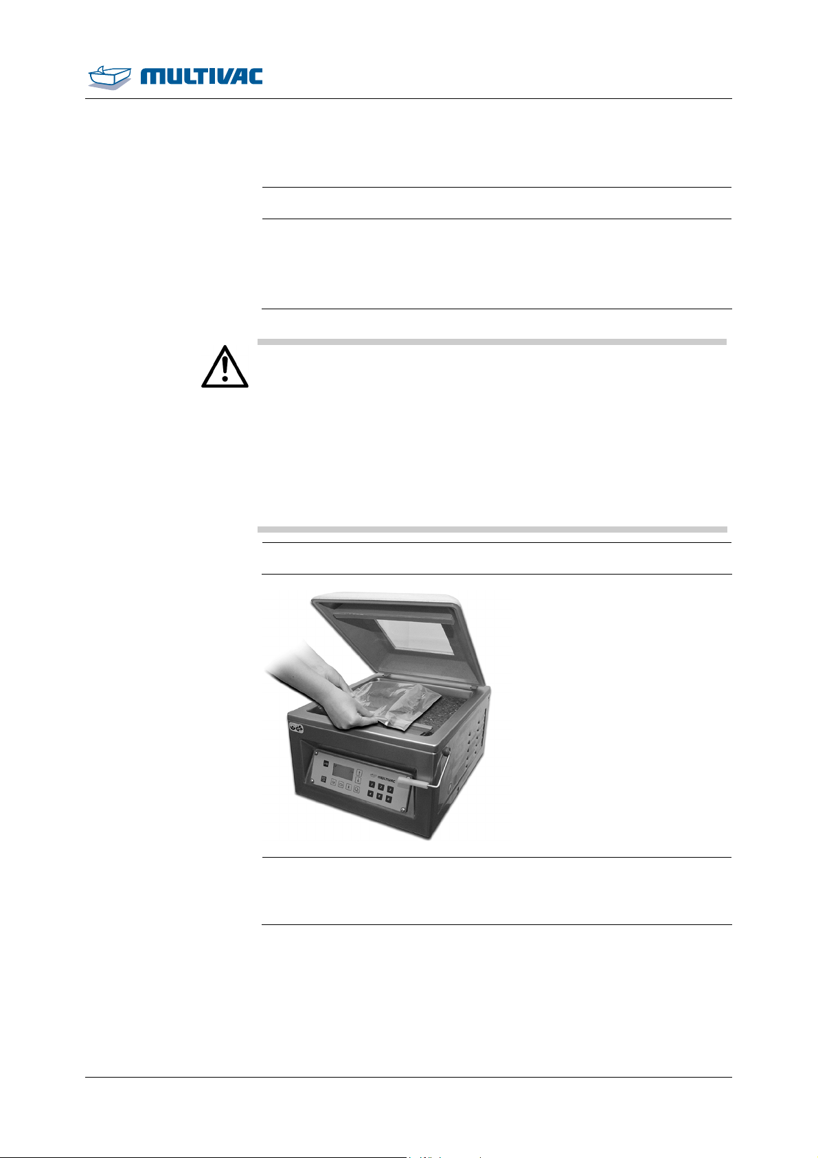
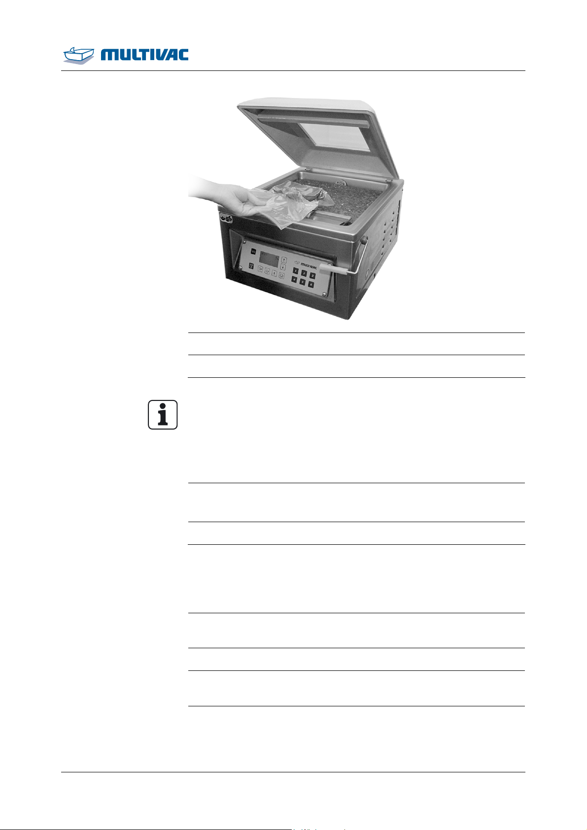
¾ Fill the film pouch.
¾ Insert film pouch.
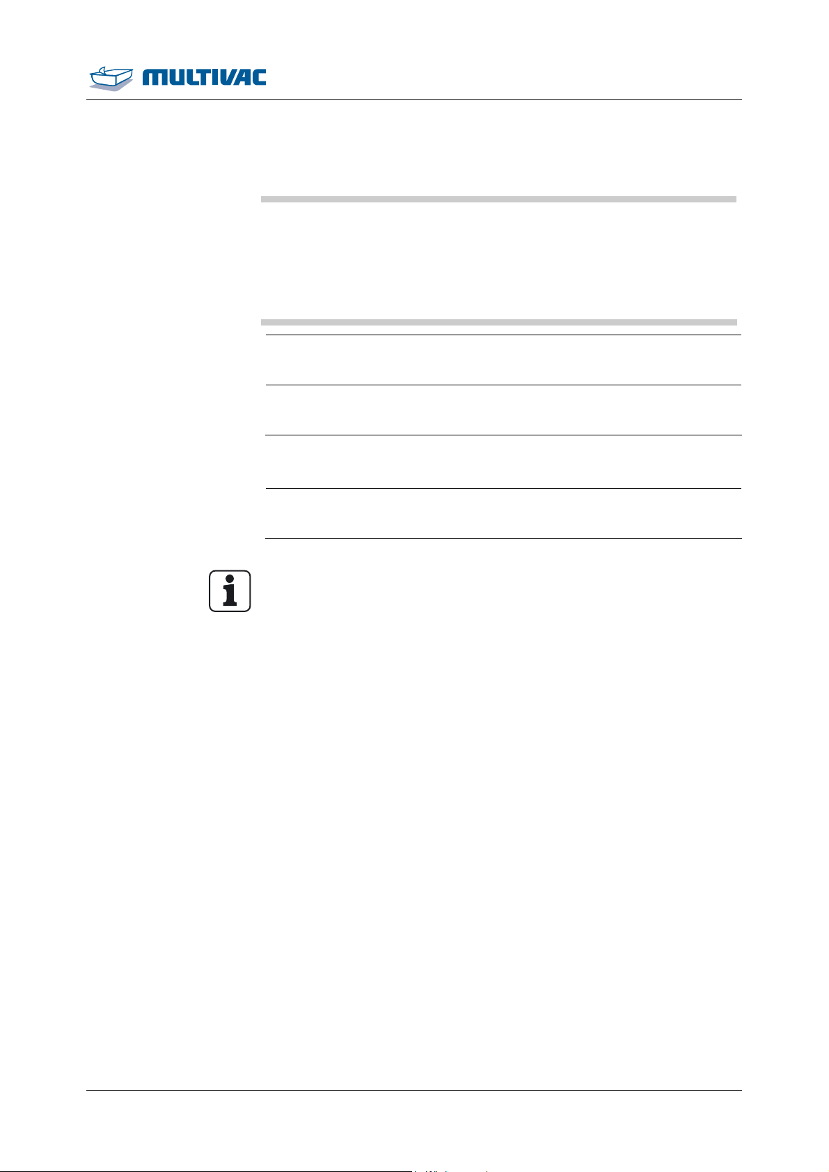
– The opening of the film pouch extends 2 to 3 cm beyond the
sealing.
11.06.2014 39
Page 40
Operation
Packing products
¾ If necessary, use spacer plates.
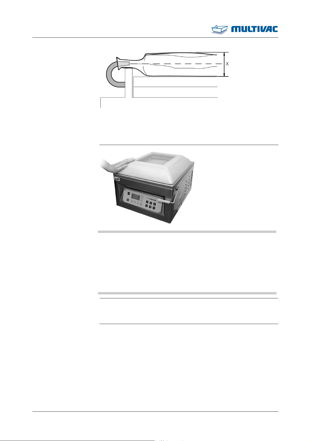
– The pouch neck is centred on the pouch height x.
¾ Pull the pouch neck flat on the sealing bar.
– The pouch neck lies on the sealing bar without creases.
NOTICE Danger of material damage!
Penetration by foreign matter (e.g. liquids, product residue, foreign
bodies) will damage the vacuum pump.
Damage can cause faults in the machine, which in turn can result in
reject packs.
¾ Cancel the evacuation process immediately if foreign matter is
sucked in.
¾ Change the oil in the vacuum pump.
¾ Close and press down the chamber lid.
– The processes in the machine run automatically.
– The chamber lid opens automatically if it is not locked.
40 11.06.2014
Page 41
Operation
Packing products
¾ Remove the finished pack.
¾ Check the pack.
Info
Visually inspect the packs on a regular basis while the machine is
running. Depending on product and pack it may be necessary to
carry out additional and considerably more complex test procedures. This is the responsibility of the operator, see Section 1.7.11
"C
HECKING THE PACKS".
¾ If necessary, adapt the settings to the product.
¾ Enter all required times and values.
¾ Save recipe, see Section 4.8.3 "SAVE RECIPE ".
4.4 Opening and closing menus
4.4.1 Calling up menus
¾ Press the <function selection> key.
– The "main menu" appears.
¾ Select the desired menu with the <arrow> keys.
¾ Press the <function selection> key.
– The desired menu appears.
¾ Select the desired submenu with the <arrow> keys.
11.06.2014 41
Page 42
Operation
Opening and closing menus
¾ Press the <function selection> key.
– The desired submenu appears.
4.4.2 Quitting menus
¾ Using the <arrow> keys, select the respective menu heading.
– The text of the menu heading changes and becomes the
(menu) function quit.
¾ Press the <function selection> key.
– The menu is exited and the system changes to the next highest
display level.
4.5 Changing values
¾ Call up the desired menu.
¾ Using the <arrow> keys, select the desired parameter.
¾ Press the <function selection> key.
– The display for the selected parameter appears.
¾ Set the value with the <arrow> keys.
– The set value is adopted.
¾ To exit the parameter, press the <Function selection> key.
4.6 Selecting and resetting access rights
4.6.1 Selecting access authorisations
¾ Call up "User" menu.
¾ Select Authorisation.
¾ Enter the password with the keys <1> to <6>.
– The corresponding access right appears in the status display.
¾ If the selected access authorisation is no longer needed, reset the
access to operator, see Section 4.6.2 "RESETTING THE ACCESS
RIGHT TO OPERATOR (BLOCKING ACCESS) ".
4.6.2 Resetting the access right to operator (blocking access)
¾ Call up "User" menu.
¾ Select Authorisation.
42 11.06.2014
Page 43
Operation
Selecting and resetting access rights
¾ Enter the password of the current access right with the keys <1>
to <6>.
– The Operator access right appears in the status display.
– Settings cannot be changed.
4.6.3 Change password for authorisation access creator
¾ Call up "PIN" menu.
¾ Select Change PIN.
¾ Enter old password with keys <1> to <6>.
¾ Enter new password with keys <1> to<6>.
¾ Confirm the new password again.
– The password has been changed.
– The status display appears.
4.6.4 To reset authorisation access creator
¾ Call up "PIN" menu.
¾ Select Reset PIN.
¾ Enter Super-PIN, see supplementary sheet "Super-PIN".
– The reset password for the authorisation access Creator ap-
pears.
– The status display appears.
4.7 Language selection
4.7.1 Selecting the language via menu
¾ Call up "User" menu.
¾ Select Language.
¾ Using the <arrow> keys, select the desired language.
¾ Press the <Function selection> key.
– The language is activated.
4.7.2 Selecting the language via the shortcut key
¾ Switch off the display with the <Machine control on/off> key.
¾ Switch on the display with the <Machine control on/off> key.
11.06.2014 43
Page 44
Operation
Language selection
¾ While the startup display is shown, press the <Function selection>
key.
– The "language selection" display appears.
¾ Using the <arrow> keys, select the desired language.
Load using keys <1> to
<6>
Loading through the
“load recipe” menu
¾ Press the <function selection> key.
– The language is activated.
4.8 Working with recipes
4.8.1 Load recipe
Info
If no recipe is saved, the message “recipe missing” appears. The
last settings remain active.
¾ Press the desired key briefly <1> to <6>.
– The selected recipe is loaded.
¾ Call up "Load recipe" menu.
¾ Select the desired recipe with the <arrow> keys.
¾ Press the <Function selection> key.
– The selected recipe is loaded.
4.8.2 Load factory settings
Info
Factory settings cannot be overwritten or deleted.
¾ Call up "Recipe loading" menu.
¾ Select recipe no. 30 with the <arrow> keys.
¾ Press the <Function selection> key.
– The factory settings are loaded.
44 11.06.2014
Page 45
Saving via keys <1> to
<6>
Saving via the “save
recipe” menu
Working with recipes
4.8.3 Save recipe
Info
When selecting an already assigned recipe number, the recipe
stored under this number is directly overwritten.
¾ Press and hold down desired key <1> to <6>.
– The message "Recipe saved" appears.
– The current values are stored in the selected recipe.
¾ Call up "Recipe, saving" menu.
Operation
¾ Using the <arrow> keys, select the desired memory location.
¾ Press the <Function selection> key.
– The current values are stored in the selected recipe.
4.8.4 Delete recipe
Info
If the currently loaded recipe is deleted, a new recipe must be
loaded.
¾ Call up "Recipe, deleting" menu.
¾ Select the recipe to be deleted with the <arrow> keys.
¾ Press the <Function selection> key.
– The message “completed” appears.
– The recipe has been deleted.
4.9 Select and set process
4.9.1 Set standard process
¾ Press <Evacuation> key briefly and enter value for Evacuation
pressure.
¾ For automatic evacuation, decrease the value until Automatic
appears.
– The machine controls the evacuation process automatically.
¾ Press <Evacuation> key briefly again and set value for Post-
evacuation time.
11.06.2014 45
Page 46
Operation
Select and set process
¾ Call up the "evacuation" menu.
¾ Set Distribution time.
¾ Set Automatic.
¾ Select Standard process.
4.9.2 To set MCV process
¾ Press <Evacuation> key briefly and enter value for Evacuation
pressure.
Info
Do not set an Evacuation pressure value in Automatic.
¾ Press <Evacuation> key briefly again and set the value for Post-
evacuation time to 0 s.
¾ Call up the "evacuation" menu.
¾ Set the value for Distribution time to 0 s.
¾ Select MCV process.
¾ Set MCV threshold.
¾ Set MCV duration.
¾ Call up the "sealing" menu.
¾ Switch off Sealing On/Off.
4.10 Setting the sealing
¾ Call up the "sealing" menu.
¾ Switch on On/off sealing.
¾ Set Delayed ventilation.
¾ Set Cooling down.
¾ Press <Sealing> key briefly and set value for Sealing time.
4.11 Entering basic settings
¾ Set Fill diaphragm.
¾ Set Ventilate diaphragm.
¾ Call up the "basic settings" menu.
4.12 Modifying and resetting machine cycles
46 11.06.2014
¾ Call up the "operating data" menu.
Page 47
Operation
Modifying and resetting machine cycles
¾ Call up "Counter" menu.
Display machine's
hours of operation
¾ Call up machine cycles.
¾ Set the value with the <arrow> keys or set to "0".
– The set value is adopted.
4.13 Display production data
4.13.1 Display total cycles of the machine
¾ Call up the "operating data" menu.
¾ Call up "Counter" menu.
¾ Select Total cycles.
4.13.2 Display hours of operation
¾ Call up the "Operating data" menu.
Display vacuum pump's
hours of operation
¾ Call up "Hours of operation" menu.
¾ Select Hours of operation.
¾ Call up the "Operating data" menu.
¾ Call up "Hours of operation" menu.
¾ Select Vacuum pump.
4.13.3 Display cycle time
¾ Call up the "operating data" menu.
¾ Select the "Cycle time" menu.
– A list of cycle times is displayed.
4.13.4 Show settings
¾ To view the settings of recipes 7 through 30, load the desired rec-
ipe via the menu, see Section 4.8.1 "LOAD RECIPE ".
11.06.2014 47
Page 48
Operation
Display production data
¾ Call up the "production data" menu.
¾ Select Settings .
– The settings of the loaded recipe appear in a list.
Info
The settings of recipes 1 through 6 can be speed dialed from the
list. To do so, load the respective recipe with the keys <1> through
<6>.
4.14 Setting the brightness of the display
¾ Call up "User" menu.
¾ Select brightness.
¾ Using the <arrow> keys set the desired brightness.
48 11.06.2014
Page 49

Cleaning
5 Cleaning
Info
Observe the safety instructions, see Section 1 "S
Clean the machine after maintenance work and repairs and disinfect if necessary.
5.1 Notes on cleaning
5.1.1 Rules of conduct
The objective of the cleaning work is to avoid risks to hygiene. If the
cleaning is insufficient or not performed properly, this may result in
the contamination of the products and to health hazards for end consumers. In addition, the machine may be damaged. Assign only
properly instructed and qualified personnel. Information on qualification and training can be obtained from MULTIVAC Service.
The ability to handle materials effectively and efficiently depends on:
• Using the proper dosage of care products.
• Observing the application time of the care products.
• Proper temperature of the mixing water.
Data sheets for the care products can be obtained from their manufacturers. The manufacturers also provide information on the maximum permissible dosages which apply in the food area.
AFETY".
5.1.2 Creating a company cleaning directive
Specify the following points:
• Required cleaning intervals.
• Care products to be used. Care products, refer to "Care products
table".
• Using the proper dosage of care products.
• Persons in charge of cleaning.
• First aid measures.
5.1.3 Measures for ensuring a long service life
NOTICE Danger of material damage!
Highly acidic or alkaline cleansers that contain chlorine create
strong vapours.
These vapours cause corrosion.
¾ Do NOT use any care products that contain chlorine or are
highly acidic or alkaline. Also, do NOT use such care products
to clean the machine surroundings.
¾ Observe the specifications of the care product manufacturers.
11.06.2014 49
Page 50
Cleaning
Notes on cleaning
NOTICE Danger of material damage!
Acidic cleansers are caustic.
These can cause plastics to become brittle and age prematurely.
¾ Do NOT shorten the cleaning intervals for acidic cleaning and
disinfection.
NOTICE Danger of material damage!
Inappropriate work on anodized aluminium parts causes a damaging of the anodized coating.
This will lead to aluminium corrosion.
¾ Do not use metal scraping tools.
¾ Do not use harsh cleansers.
¾ Do not use cleaning devices with abrasive surface.
¾ Residues of cleansers and other aggressive deposits must be
removed immediately.
WARNING
Regular and proper care helps to maintain the machine's value. The
best protection against harmful influences is to clean and disinfect the
machine on a regular basis. The longer product residue and other
aggressive deposits remain on the machine, the more harmful their
corrosive effects will be.
If used incorrectly, care products can damage components made of
rubber or plastic. Before applying care products, please take time to
read the instructions and warnings provided by the manufacturer.
5.1.4 Parameters for pre-rinsing and after-rinsing water
• Low pressure of max. 4 bar to 6 bar (58 psi to 88 psi).
• Do not rinse with steam jets or high-pressure cleaners.
• Fan nozzle: 5 ° to 15 ° inclination, approx. 3/16 '' nozzle opening.
• Temperature: max. 60 °C (140 °F).
• Quality of after-rinsing water: drinking water quality.
5.1.5 Handling cleansers
Chemical burn hazard!
Cleansers are caustic. Caustic effects are NOT noticed immediately.
Contact with the skin can cause burns.
¾ Wear the prescribed personal protective equipment when han-
dling cleansers.
¾ Observe the manufacturer's instructions.
• For type of cleander refer to the "Care products table".
50 11.06.2014
Page 51
Cleaning
Notes on cleaning
• The quantity of cleanser is not the decisive factor for successful
cleaning.
– Applying amounts in excess of the proper dosage does not im-
prove or accelerate cleaning efficiency, but only hinders the required rinsing off of the cleanser.
• Dried cleanser residues make cleaning more difficult and pro-
longed.
– Even the smallest residues can inhibit the effect of the disinfec-
tion.
– Check by measuring the pH factor of the post-rinsing water.
• Regular checks of cleaning (i.e. by contact tests) reduces the risk
of product contamination.
• Insufficient cleaning cannot be compensated for by doubling the
concentration of the disinfectants.
5.1.6 Use with disinfectant
WARNING
WARNING
Fire hazard!
Alcohol-based disinfectants are highly flammable.
Fire, naked light or smoking ignites the disinfectant and can thus
cause fires.
¾ When disinfecting the machine, flames or naked lights are pro-
hibited.
¾ Smoking is prohibited.
¾ Observe the instructions of the disinfectant manufacturer.
Health hazard!
Incorrect use of disinfectant can contaminate the product with
chemicals or decrease the effectiveness of disinfection.
This can pose serious health hazards for consumers.
¾ Follow the instructions of the disinfectant manufacturer.
¾ Only rinse after disinfection if required by disinfectant manufac-
turer.
¾ Observe regional hygiene regulations.
¾ Create a company cleaning guideline.
• For type of disinfectant refer to the "Care products table".
– For water-sensitive components only use alcohol-based disin-
fectant.
– For all other components use disinfectants which are for exam-
ple based on quaternary ammonium compounds.
11.06.2014 51
Page 52
Cleaning
Notes on cleaning
WARNING
5.1.7 Corrosion protection and lubrication
Health hazard!
Excess lubricants can accumulate at lubrication points.
Excess grease has no lubricating function; however, it can breed
micro-organisms and contaminate the product.
¾ Check the lubricating points regularly for the accumulation of
excess lubricants.
¾ Remove any excess lubricants.
NOTICE Danger of material damage!
Residues of cleansers and disinfectants produce corrosion.
Corrosion can destroy the machine.
¾ After every cleaning, including cleaning of the surroundings
(floor, adjacent machines, etc.), thoroughly rinse with water of
drinking water quality or clean by hand.
Wet cleaning
Dry cleaning
WARNING
• Kind of anti-corrosion agent, refer to "Care products table".
• Only use H1 or FDA-approved lubricants and anti-corrosion agents.
• Checking the microbiological stability of the anti-corrosion agent
and lubricants regularly helps reduce the risk of product contamination.
5.1.8 Cleaning devices
Health hazard!
The cleaning devices will become germ hot spots if they are not
cleaned often enough.
This can cause cross contamination, which will damage the product.
¾ Use only plastic brushes and brooms.
¾ Clean the cleaning devices daily and apply disinfectant after-
wards.
The exhaust air emitted by the vacuum cleaner and whirled up must
comply with the prescribed limit values for the packaging environment.
Accordingly, the appropriate filter elements must be used in the vacuum cleaner.
52 11.06.2014
Page 53
Cleaning
Cleaning the machine
5.2 Cleaning the machine
Info
• The recommended daily cleaning tasks recommended here must
be supplemented by the intensive cleaning procedure according
to the degree of dirt.
• Cleaning personnel must be instructed for the cleaning work by
the operating company.
• The sequence of the described tasks is to be followed exactly.
5.2.1 Performing daily cleaning
Info
• The intensive cleaning may only be performed by specially
trained personnel.
• The sequence of the described tasks is to be followed exactly.
• In the following, optional equipment versions are also described.
Only perform steps that correspond to the version of the machine.
• Always clean the machine from top to bottom.
• For all cleaning work, follow the safety instructions, see Section
5.1 "N
• The illustrations are examples.
OTES ON CLEANING".
Preparing for cleaning
¾ Remove all products from the machine.
¾ Switch off the machine.
¾ Disconnect the machine from the mains electricity.
¾ Cover the mains plug with waterproof plastic bags.
¾ Close the stop valve for the gas supply, if part of the machine.
¾ Allow the machine and sealing bars to cool down.
¾ Store empty, new film pouches outside the room in a clean, dry
place during the cleaning procedure.
¾ Remove all waste (e.g. product scraps, film trim) on or around the
machine.
11.06.2014 53
Page 54
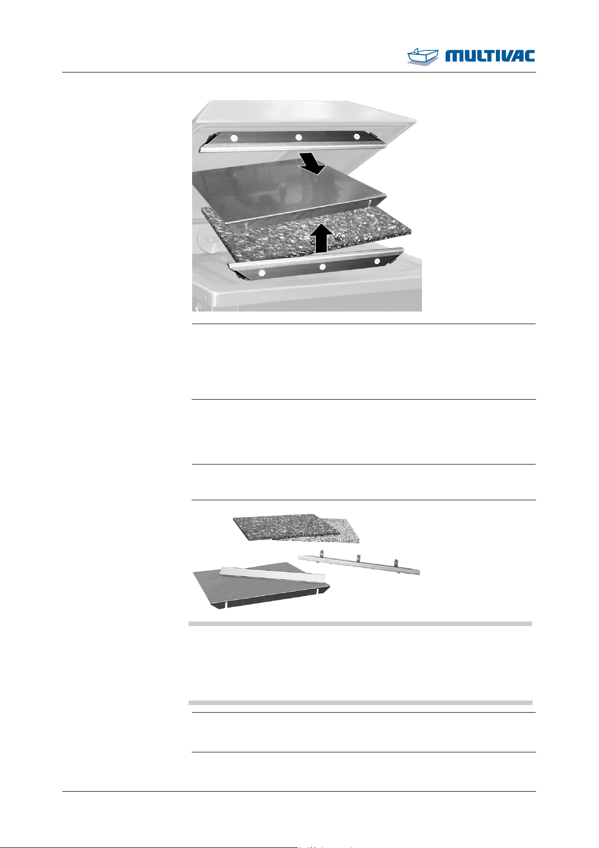
Cleaning
Cleaning the machine
Cleaning and
disinfecting dismantled
components
¾ Remove the following components:
– Diagonal insert with support bracket.
– Spacer plates.
– Sealing bars
– Insertable counter-pressure bar.
¾ Take the removed components to a separate room suitable for
wet cleaning
NOTICE Danger of material damage!
The Teflon tape of the sealing bar is very sensitive.
Improper cleaning can damage the Teflon tape.
¾ Clean the Teflon tape only with a soft cloth.
¾ Do NOT scratch the Teflon tape.
¾ Clean dismantled components manually with cleaning solution.
¾ Thoroughly clean the inert gas nozzles.
54 11.06.2014
Page 55
Cleaning
Cleaning the machine
¾ Wait until the contact time has elapsed (see instructions of
cleanser manufacturer).
¾ Wipe with new cloth and water of drinking quality.
¾ Inspect for dirt and cleanser residues.
¾ If necessary, perform another manual cleaning and wipe it off.
¾ Disinfect components with alcohol-based disinfectant:
¾ Thoroughly disinfect the inert gas nozzles.
¾ Wait until the contact time has elapsed (see instructions of disin-
fectant manufacturer).
Clean the machine and
the floor.
¾ Clean the floor with a rubber wiper.
¾ Dispose of the waste properly.
¾ Apply cleanser to the floor with a low-pressure foaming device.
¾ Wait until the contact time has elapsed (see instructions of
cleanser manufacturer).
¾ Rinse off the floor with water of drinking quality.
NOTICE Danger of material damage!
Penetration by foreign matter (e.g. liquids, product residue, foreign
bodies) will damage the vacuum pump.
Damage can cause faults in the machine, which in turn can result in
reject packs.
¾ Do NOT spray directly on the covers of the suction openings in
the chamber.
¾ Manually clean the entire machine, including the table, with clean-
ing solution.
¾ Only clean the viewing window in the chamber lid manually
with a soft cloth or a soft brush.
¾ Wait until the contact time has elapsed (see instructions of
cleanser manufacturer).
¾ Wipe with new cloth and water of drinking quality.
¾ Inspect the entire machine and the floor for dirt and cleanser resi-
dues.
11.06.2014 55
Page 56

Cleaning
Cleaning the machine
Disinfect the machine
and the floor.
NOTICE Danger of material damage!
¾ If necessary, clean and wipe off again.
Penetration by foreign matter (e.g. liquids, product residue, foreign
bodies) will damage the vacuum pump.
Damage can cause faults in the machine, which in turn can result in
reject packs.
¾ Do NOT spray directly on the covers of the suction openings in
the chamber.
¾ Disinfect entire machine, including table, with alcohol-based disin-
fectant.
Complete cleaning
¾ Close chamber lid and lock it in place.
¾ Use a hand-held spray lance to apply disinfectant to the floor.
¾ Wait until the contact time has elapsed (see instructions of disin-
fectant manufacturer).
¾ If necessary, rinse the floor with water of drinking quality; see in-
structions of the disinfectant manufacturer.
¾ Remove the plastic bag from the mains plug.
¾ Dispose of plastic bags properly. For reasons of hygiene, never
reuse bags
56 11.06.2014
Page 57
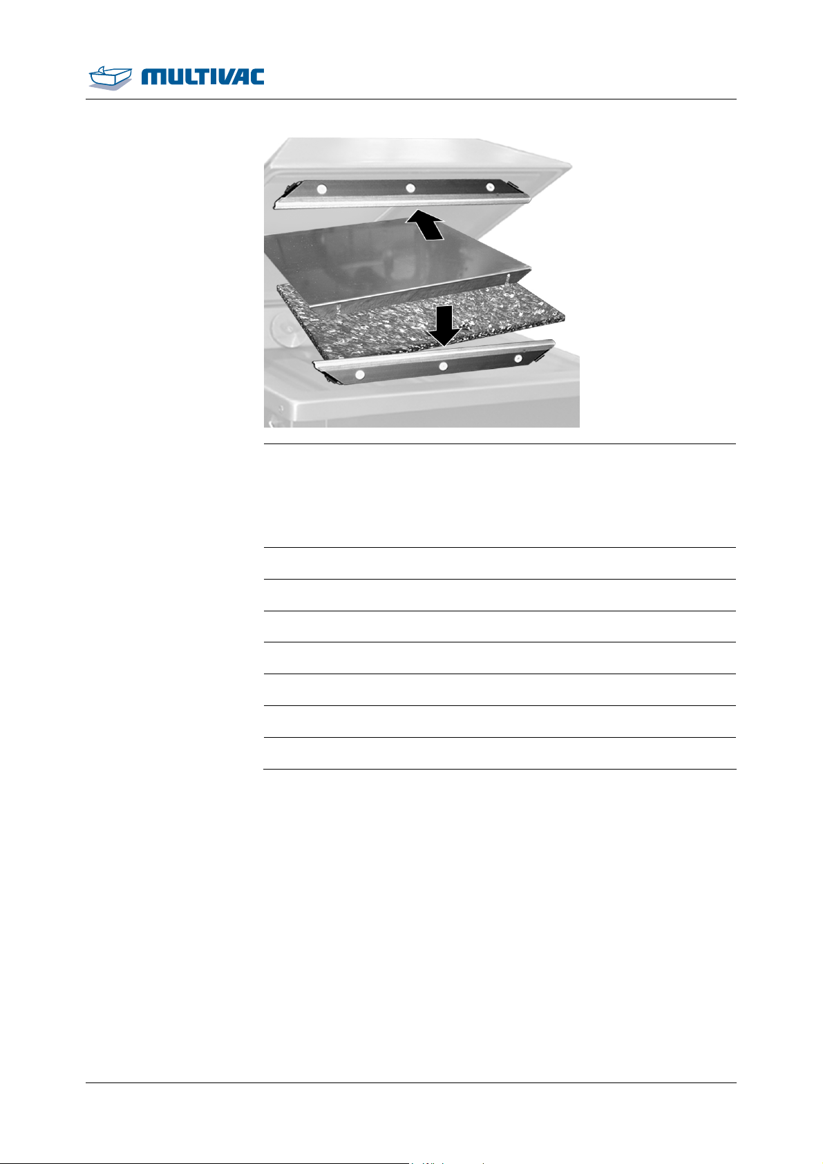
Cleaning
Cleaning the machine
¾ Attach the following components:
– Insertable counter-pressure bar.
– Sealing bars
– Spacer plates.
– Diagonal insert with support bracket.
¾ Disinfect the entire loading area with alcohol-based disinfectant.
¾ Leave the chamber lid open to dry.
¾ If present, open the stop valve for the gas supply.
¾ Connect the machine to the mains electricity.
¾ Clean cleaning implements (e.g. rubber wipers, brushes).
¾ Place cleaning implements in disinfectant solution-
¾ Unpack the film pouches and lay them ready.
11.06.2014 57
Page 58
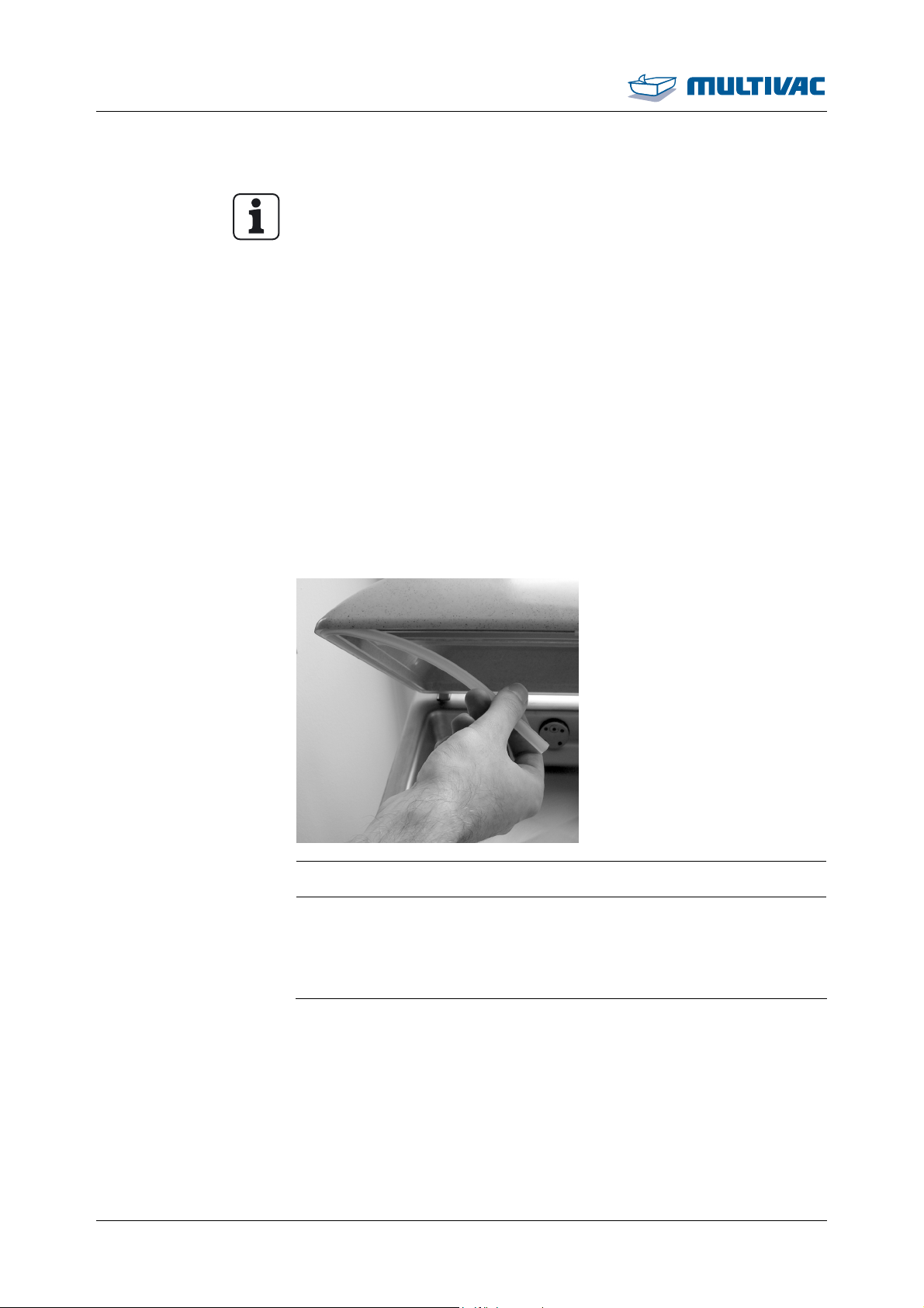
Cleaning
Cleaning the machine
5.2.2 Performing intensive cleaning
Info
• Intensive cleaning complements daily cleaning. As part of this
process additional cleaning measures are required depending on
the degree of contamination of the components described in this
chapter.
• The intensive cleaning may only be performed by specially
trained personnel. Information on qualifications and training can
be obtained from our service personnel.
• The sequence of the described tasks is to be followed exactly.
• Always clean the machine from top to bottom.
• In the following, optional equipment versions are also described.
Only perform steps that correspond to the version of the machine.
• For all cleaning work, follow the safety instructions, see Section
5.1 "N
• The illustrations are examples.
OTES ON CLEANING".
¾ Remove chamber lid gasket from the groove.
¾ Perform daily cleaning, see Section 5.2.1 "PERFORMING DAILY
CLEANING ".
¾ Clean and disinfect the chamber lid gasket together with the
removed components.
58 11.06.2014
Page 59
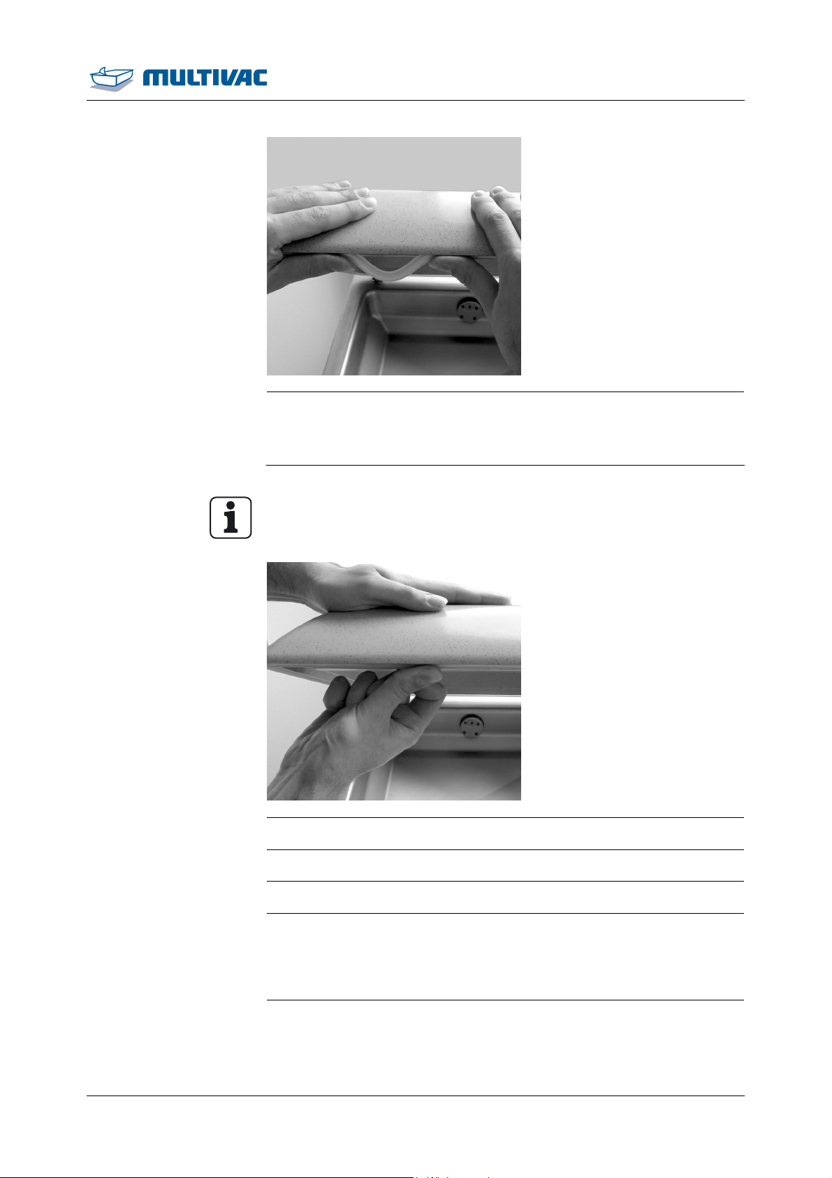
Cleaning
Cleaning the machine
¾ Insert the dry chamber lid gasket in the groove of the lid.
¾ If the chamber lid gasket or groove is wet, dry with a new cloth
or sterile compressed air.
Info
During insertion, do not stretch the gasket.
¾ Smooth out gasket.
¾ Disinfect gasket with alcohol-based disinfectant.
¾ Switch on the machine.
¾ Close and press down the chamber lid and observe the pressure
shown in the display.
– The pressure drops: the chamber is airtight.
– The pressure does not drop: the chamber is not airtight.
¾ If the chamber is not airtight, check the chamber lid gasket:
¾ Smooth out gasket.
11.06.2014 59
Page 60
Cleaning
Cleaning the machine
¾ Disinfect gasket with alcohol-based disinfectant.
¾ Wait until the contact time has elapsed (see instructions of dis-
infectant manufacturer).
¾ Switch off the machine.
5.3 Care products table
Recommended care products:
Type Manufacturer Designation
Cleansers, neutral
Cleansers, alkaline
Cleansers, acidic
Ecolab Europa P3-topax 12
Ecolab USA Quorum Pink II
Shureclean VK10 Diversey Europe
JD Shureclean Plus VK9
Diversey USA
Shureclean VK10
JD Shureclean Plus VK9
Ecolab Europa P3-topactive LA
JD Ultraclean VK3 Diversey Europe
Diverfoam SMS HD VF22
Diversey USA
JD Ultraclean VK3
Diverfoam SMS HD VF22
P3-topax 52 Ecolab Europa
P3-topax 56
Quorum Red Ecolab USA
Foam shine
Diversey Europe
JD Acifoam VF10
Diversey USA
Disinfectants
P3-topax 91 Ecolab Europa
P3-topax 990
Ecolab USA Ster-Bac
JD Divosan extra VT55 Diversey Europe
JD Suredis VT1
Diversey USA
JD Divosan extra VT55
JD Suredis VT1
Disinfectants (alcohol-based) Ecolab Europa P3-alcodes
60 11.06.2014
Page 61

Cleaning
Care products table
Type Manufacturer Designation
Diversey Europe
JD Divodes FG VT29
Diversey USA
Anti-corrosion agents
Esso Primol 352
Castrol Optimol F+D Fluid Spray
Klüber Lubrication Klüberfood NH1 K 32
Stainless steel care products Ecolab Europa P3-proguard MC
All recommended anti-corrosion agents and stainless steel care
products are food compatible.
Buying source:
• Ecolab: www.ecolab.com
• Diversey: www.diversey.com
• Esso: www.exxonmobil.com
• Castrol: www.castrol.com
• Klüber Lubrication: www.klueber.com
11.06.2014 61
Page 62
Maintenance
DANGER
6 Maintenance
Dangerous voltage!
Switching off the machine does not rid it of electrical current.
Touching electrically charged components can cause serious or
even fatal injuries.
Before performing any cleaning or service work:
¾ Disconnect the machine's power supply from the mains electric-
ity.
¾ Have work in the control cabinet performed by authorised tech-
nicians only.
Info
Observe the safety instructions, see Section 1 "S
Clean the machine after maintenance work and repairs and disinfect if necessary.
AFETY".
6.1 Maintenance schedule
As needed
Page Complet
ed
Entire machine Wipe test
Every 8 operating hours or daily
Page Complet
Vacuum pump. Perform the pump protection function.
Entire machine Visual inspection
Entire machine Alkaline cleaning and disinfection
Entire machine Intensive cleaning
Chamber lid viewing
Visual inspection
window
Chamber lid gasket Visual inspection
64
63
63
63
64
64
64
ed
Sealing bar Visual inspection
Vacuum pump. Checking oil level, refilling
64
65
62 11.06.2014
Page 63
Maintenance
Maintenance schedule
Every 50 operating hours or weekly
Page Complet
ed
Entire machine Acidic cleaning and disinfection
Connections Visual inspection
Vacuum system Check
64
64
65
Every 1000 opearating hours or yearly
Page Complet
ed
Vacuum pump. Oil change
Vacuum pump. Exchanging the air de-oiling element
65
65
6.2 Recommended maintenance
6.2.1 Vacuum pump. - Perform the pump protection function.
¾ Perform the pump protection function, for this switch off the ma-
chine, see Section 4.2 "SWITCHING OFF THE MACHINE".
6.2.2 Entire machine - Visual inspection
¾ Check the entire machine exterior for damage.
¾ Check that all warning signs are present.
¾ Check that all safety guards are mounted and intact.
6.2.3 Entire machine - Alkaline cleaning and disinfection
¾ See company cleaning guidelines.
¾ See the cleaning measures specified by the manufacturer, see
Section 5 "CLEANING".
11.06.2014 63
Page 64
Maintenance
f
Recommended maintenance
6.2.4 Entire machine - Wipe test
¾ Perform wipe tests to check the result of the cleaning and disin-
fection procedures.
See the company cleaning instructions and recommendations, see Section 5 "CLEANING".
6.2.5 Entire machine - Acidic cleaning and disinfection
¾ See company cleaning guidelines.
¾ See the cleaning measures specified by the manufacturer, see
Section 5 "CLEANING".
6.2.6 Entire machine - Intensive cleaning
¾ If there is any contamination perform Intensive Cleaning see
¾ See company cleaning guidelines.
¾ Check the components described in Intensive Cleaning for con-
tamination
Section 5.2.2 "PERFORMING INTENSIVE CLEANING"
6.2.7 Chamber lid viewing window - Visual inspection
¾ Check the viewing window in the chamber lid for damage (e.g
scratches, cracks).
¾ If the viewing window in the chamber lid is damaged have it re-
placed immediately by the manufacturer.
6.2.8 Chamber lid gasket - Visual inspection
¾ Check gasket for damage.
¾ Have the chamber lid gasket replaced by the service department i
necessary.
6.2.9 Sealing bar - Visual inspection
¾ Check sealing bar for damage.
¾ If necessary, replace the sealing bar, see Section 6.4 "REPLACE
THE SEALING BAR".
6.2.10 Connections - Visual inspection
64 11.06.2014
¾ Disconnect the machine from the mains electricity.
Page 65
Maintenance
Recommended maintenance
¾ Check power cable for damage.
6.2.11 Vacuum pump. - Checking oil level, refilling
¾ Disconnect the machine from the mains electricity.
¾ Check the oil level on the oil sight glass.
¾ If water is present in the oil, notify the service department.
¾ If necessary, refill oil.
6.2.12 Vacuum pump. - Oil change
¾ Change the oil in the vacuum pump, see Section 6.5 "CHANGE THE
OIL IN THE VACUUM PUMP".
6.2.13 Vacuum pump. - Exchanging the air de-oiling element
¾ Have the air de-oiling element exchanged by the service depart-
ment.
6.2.14 Vacuum system - Check
¾ Perform a vacuum test, see Section 6.3 "PERFORMING THE VAC-
UUM TEST".
6.3 Performing the vacuum test
¾ Call up the "Service" menu.
¾ Call up the "test" menu.
¾ Select Vacuum test.
¾ Switch on the vacuum test.
¾ Return to the status display.
¾ Close and press down the chamber lid.
– The evacuation system is being checked.
– The processes in the machine run automatically.
– The corresponding diagnostic message appears.
– The chamber lid opens.
¾ Acknowledge the diagnostic message.
– The vacuum test is switched off.
11.06.2014 65
Page 66
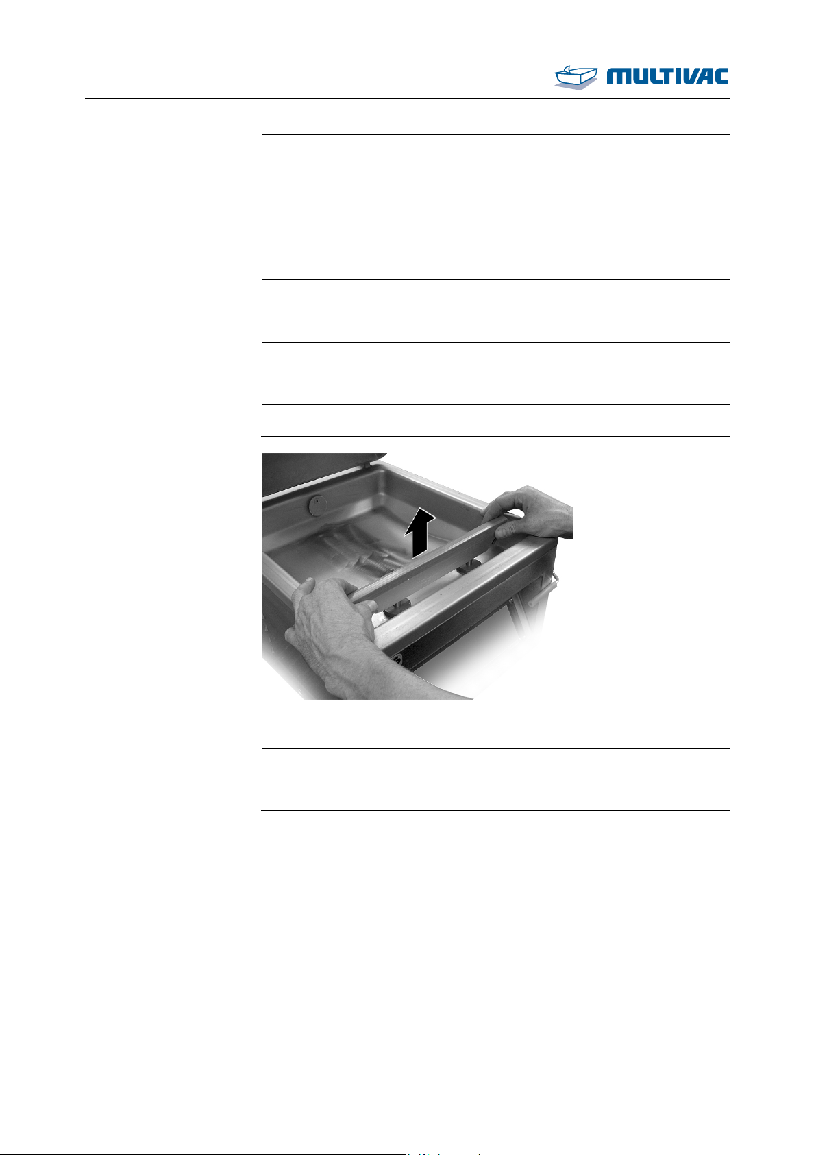
Maintenance
Performing the vacuum test
¾ If the vacuum test is not successful, see the displayed diagnostic
message to correct the fault, see Section 7 "TROUBLESHOOTING".
6.4 Replace the sealing bar
6.4.1 Remove the sealing bar
¾ Switch off the machine.
¾ Disconnect the machine from the mains electricity.
¾ Open the chamber lid.
¾ Let the sealing bar cool down.
¾ Pull out the sealing bar.
6.4.2 Install the sealing bar
66 11.06.2014
¾ Disconnect the machine from the mains electricity.
¾ Install the sealing bar on the carriers.
Page 67
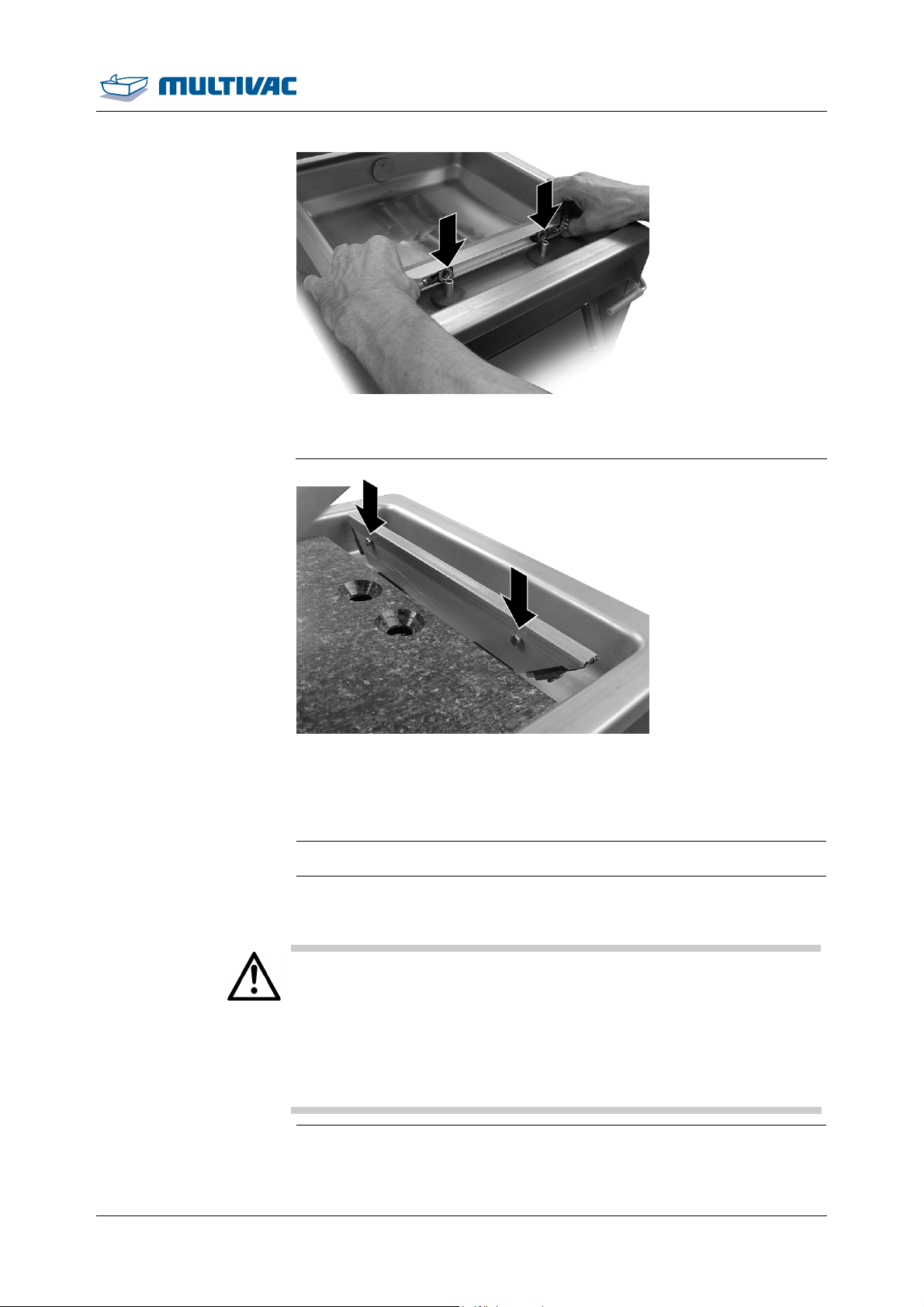
Maintenance
r
Replace the sealing ba
¾ Install the sealing bar in such a way that the screws on the
sealing bar point to the middle of the chamber.
6.5 Change the oil in the vacuum pump
6.5.1 Drain oil
WARNING
¾ Switch off the machine.
¾ Disconnect the machine from the mains electricity.
Burn hazard!
The surface of the vacuum pump can reach temperatures of over
70 °C during operation.
Touching the vacuum pump can lead to burns.
Before performing any work on the vacuum pump:
¾ Allow the vacuum pump to cool down.
¾ Wear personal protective equipment.
¾ Allow the vacuum pump to cool down.
11.06.2014 67
Page 68
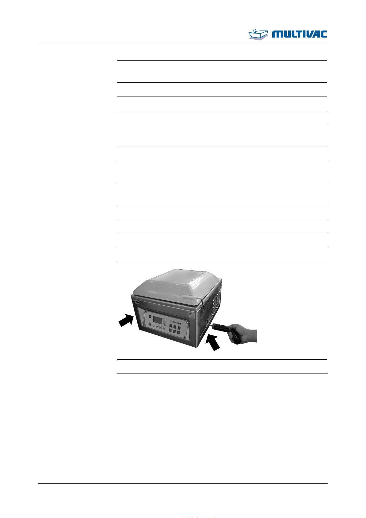
Maintenance
Change the oil in the vacuum pump
¾ Hold a container to catch the oil under the drain opening (e.g. an
empty oil bottle).
¾ Unscrew the screw plug of the drain opening.
¾ Drain the oil completely.
¾ Replace the sealing ring in the screw plug.
¾ Insert the screw plug with the sealing ring in the drain opening and
screw it tight.
¾ Dispose of old oil properly.
¾ Fill new oil into the vacuum pump, see Section 6.5.2 "ADDING OIL
TO THE VACUUM PUMP".
6.5.2 Adding oil to the vacuum pump
¾ Switch off the machine.
¾ Disconnect the machine from the mains electricity.
¾ Empty chamber completely.
¾ Close chamber lid and lock it in place.
68 11.06.2014
¾ Unscrew the lateral screws.
Page 69
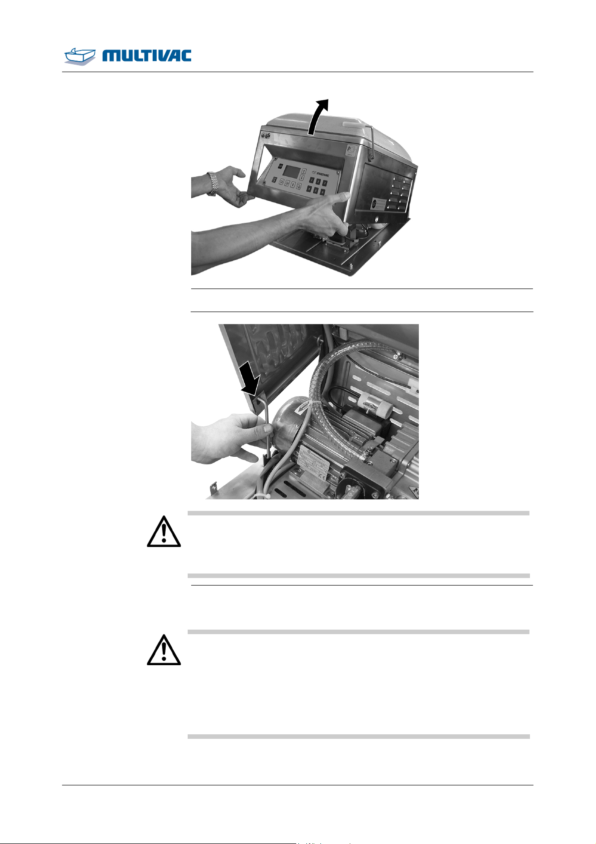
Maintenance
Change the oil in the vacuum pump
¾ Open housing.
Danger of crushing!
The housing is heavy.
WARNING
Reaching under the opened housing can cause crushing injuries.
¾ Always support the opened housing.
¾ Support housing with supporting bar.
Burn hazard!
The surface of the vacuum pump can reach temperatures of over
WARNING
70 °C during operation.
Touching the vacuum pump can lead to burns.
Before performing any work on the vacuum pump:
¾ Allow the vacuum pump to cool down.
¾ Wear personal protective equipment.
11.06.2014 69
Page 70
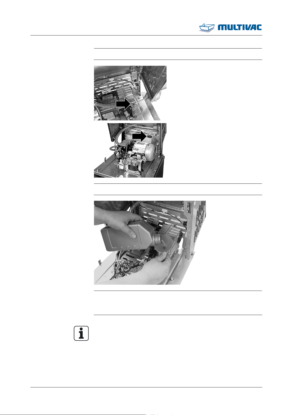
Maintenance
Change the oil in the vacuum pump
¾ Allow the vacuum pump to cool down.
¾ Unscrew the screw plug of the oil fill opening.
¾ Fill the vacuum pump with oil up to the middle of the oil sight
glass. Use only oils that are approved by the manufacturer, see
'Spare Parts' section or the spare parts list.
Info
Only use low odour synthetic oil if foodstuffs are being packed.
70 11.06.2014
Page 71
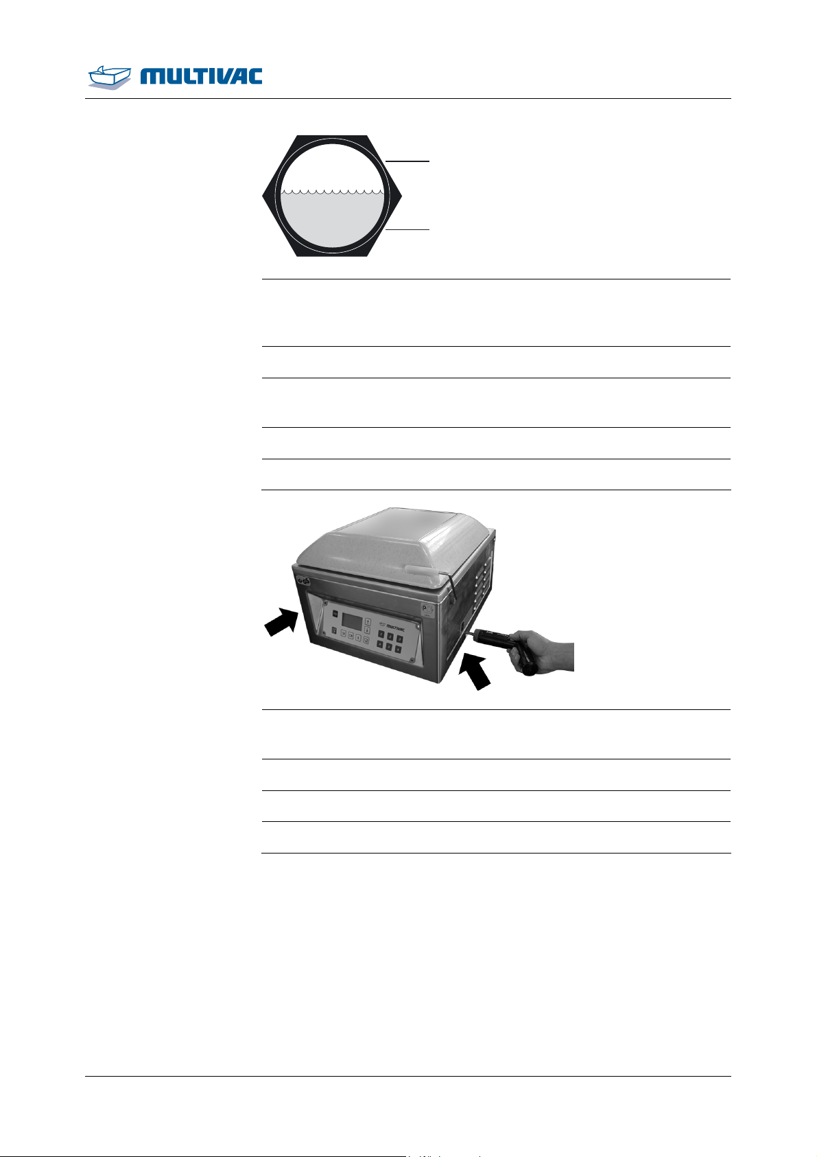
Maintenance
Change the oil in the vacuum pump
max.
min.
¾ Check oil level on the oil sight glass:
– The oil level should reach the middle of the oil sight glass.
– If oil level is under the MIN mark, add oil.
¾ Replace the sealing ring in the screw plug.
¾ Insert the screw plug with the sealing ring in the fill opening and
screw it tight.
¾ Hold housing and take supporting rod out of the holder.
¾ Close housing.
¾ Tighten lateral screws.
– The housing is closed and tight.
¾ Connect the machine to the mains electricity.
¾ Switch on the machine.
¾ Check the oil level after a couple of machine cycles.
11.06.2014 71
Page 72
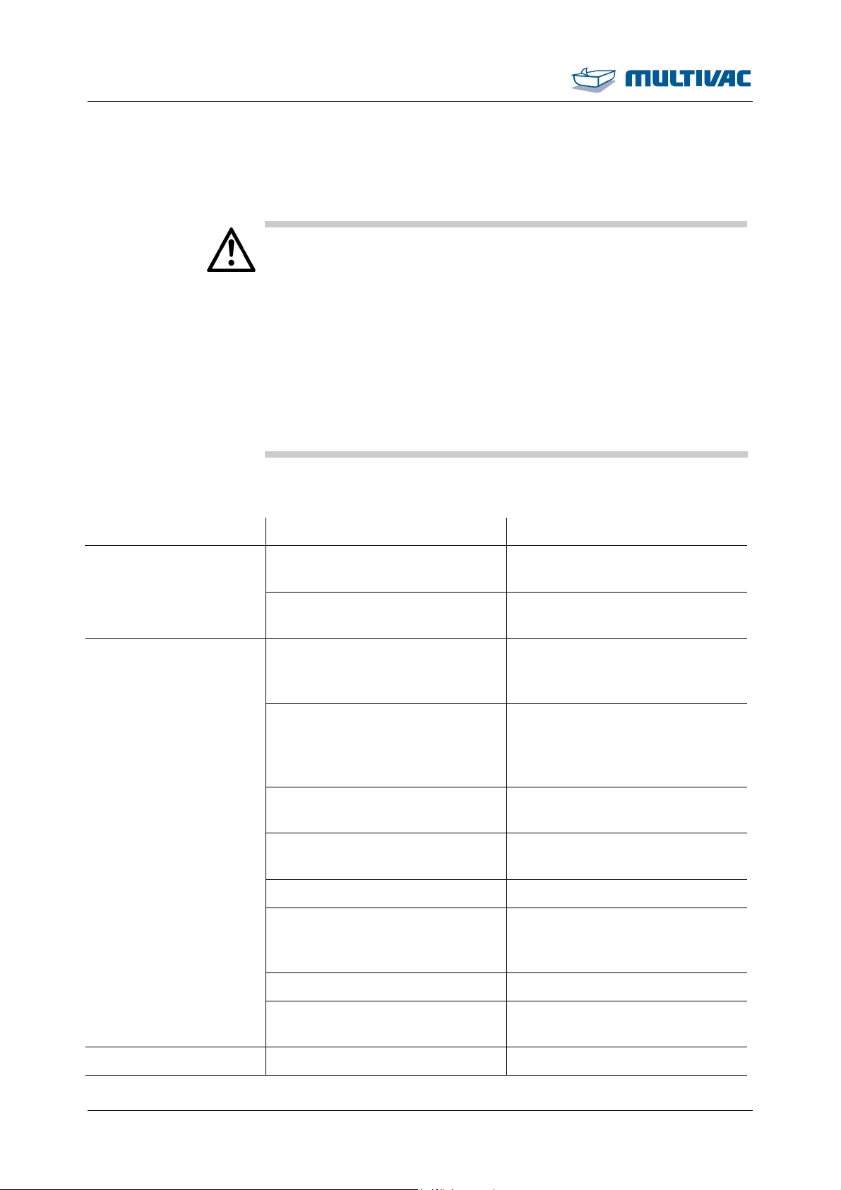
Troubleshooting
WARNING
7 Troubleshooting
Injury hazard!
Ignorance of proper machine handling is very dangerous.
Improper handling can lead to serious injuries.
For all service and repair work:
¾ Make sure you observe the safety instructions and accident
prevention regulations.
¾ Disconnect the unit's power supply from the mains electricity.
¾ Only qualified electricians are permitted to work on electrical
modules.
¾ Service and repair work should be carried out by authorised
technicians only.
7.1 Malfunctions with diagnostic message
Symptom Cause Solution
69
• Vacuum pump does not
switch off.
• Ventilation valve does not
open.
• Value for the Evacuation
pressure is set so low that it
cannot be reached.
• Vacuum hose between the
chamber and the vacuum
sensor is clogged, missing or
leaking.
• Vacuum hose is loose, leaking
or clogged.
• Chamber lid gasket is not air-
tight.
• Vacuum sensor is defective. • Notify the service.
• Notify the service. 67
• Notify the service.
• Correct the value for Evacua-
tion pressure.
• Notify the service.
• Notify the service.
• Notify the service.
• Vacuum pump is not being
• Notify the service.
triggered or the vacuum pump
is defective.
• Vacuum pump is leaky. • Notify the service.
• Filter in the line to the vacuum
• Notify the service.
sensor is dirty and blocked.
80 • Leak in hose connections. • Notify the service.
72 11.06.2014
Page 73
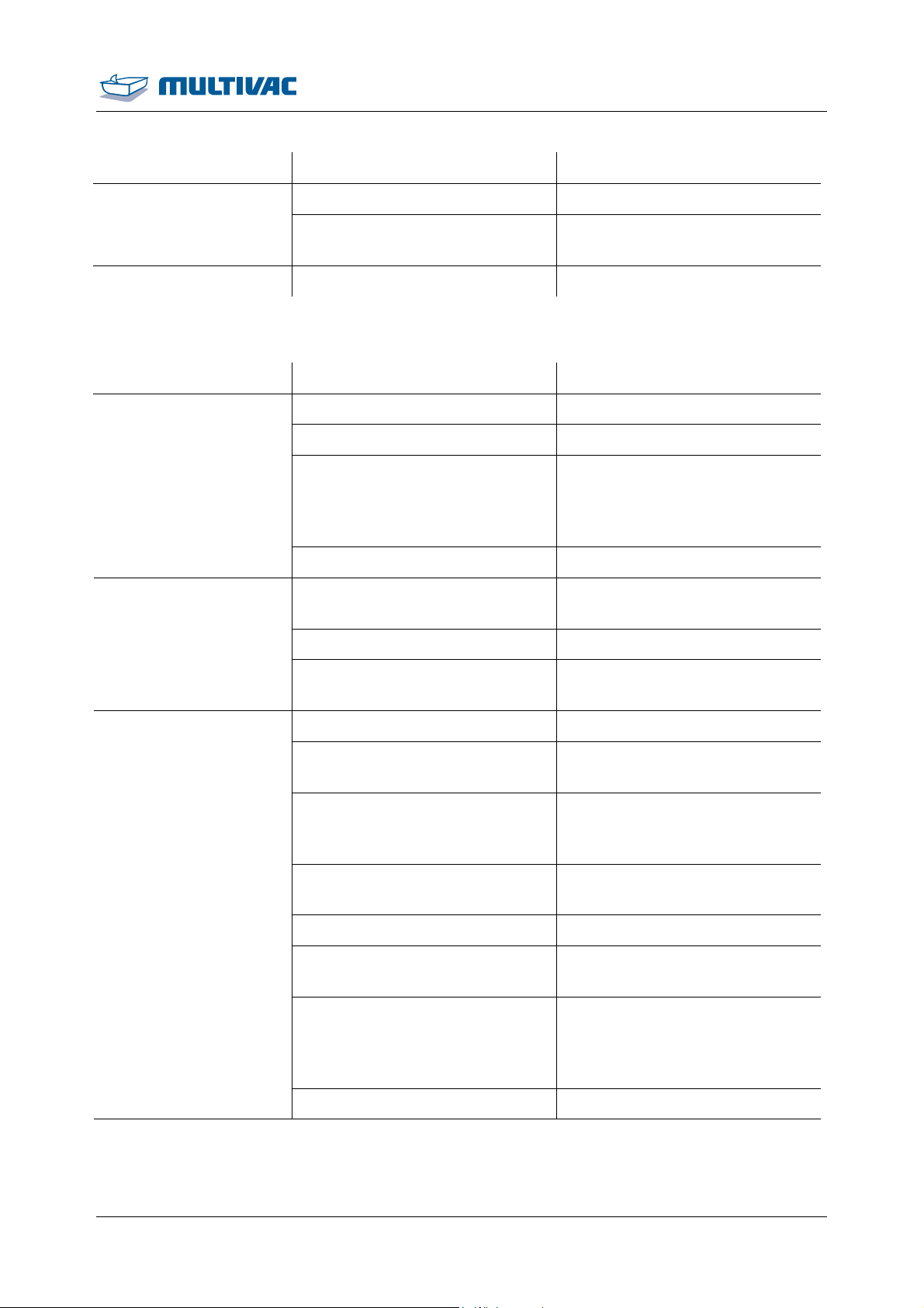
Troubleshooting
Malfunctions with diagnostic message
Symptom Cause Solution
• Leak in vacuum hose. • Notify the service.
• The vacuum sensor and as-
• Notify the service.
sociated line is leaking.
81 • Sealing diaphragm leaks. • Notify the service.
7.2 Malfunctions without diagnostic message
Symptom Cause Solution
Machine does not run.
Chamber lid does not
remain closed despite
pump running.
• Machine is switched off. • Switch on the machine.
• Power cord is unplugged. • Plug in the power cord.
• Ambient temperature too low. • Operate the machine only at
permissible ambient temperature, see "Technical Specifications".
• Vacuum pump defective. • Notify the service.
• Chamber lid pressed closed
too briefly.
• Press chamber lid closed
more firmly and for longer.
• Chamber lid gasket is dirty. • Clean the chamber lid gasket.
• Chamber lid gasket is dam-
• Notify the service.
aged.
Seal seam not airtight pack is slack.
• Sealing time is set incorrectly. • Correct the sealing time.
• Target pressure value incorrectly set.
• Pouch neck is clamped by
chamber lid.
• Correct the target pressure
value.
• Insert the film pouch so that
the pouch neck lies within the
chamber.
• Seal seam is dirty. • Keep sealing bar and film
pouch clean.
• Pack not air-tight. • Use a new film pouch.
• Film pouch not suitable. • Use a film pouch suitable for
sealing.
• The sealing force is not suffi-
cient.
• Test settings. Sufficient sealing force is only achieved if
the target pressure is set under 400 mbar.
• Sealing bar damaged. • Replace sealing bar.
11.06.2014 73
Page 74
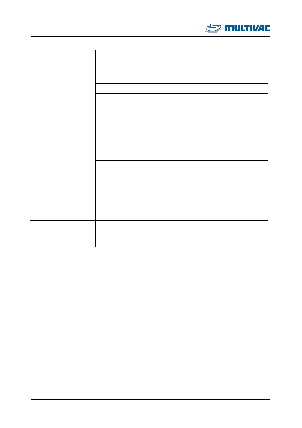
Troubleshooting
Malfunctions without diagnostic message
Symptom Cause Solution
The target pressure
value is not reached.
• The set target pressure is not
achieved (e.g. product contains water).
• Chamber lid gasket is dirty. • Clean the chamber lid gasket.
• Insufficient oil quantity or oil in
the vacuum pump is too old.
• Chamber lid gasket is damaged.
• Evacuation system is not airtight.
• Air de-oiling element defective.
• Oil check valve of vacuum
pump is blocked.
• Air de-oiling element is
clogged.
• Vacuum pump defective. • Notify the service.
High oil consumption. • Air de-oiling element is
clogged.
• Set a higher target pressure.
• Refill or replace oil.
• Notify the service.
• Notify the service.
• Notify the service. Odour or smoke.
• Notify the service.
• Notify the service. Machine is very loud.
• Notify the service.
Oil leaks out of machine.
• Screw plugs or oil sight glass
not tight.
• Tighten screw plugs and oil
sight glass.
• Vacuum pump defective. • Notify the service.
74 11.06.2014
Page 75
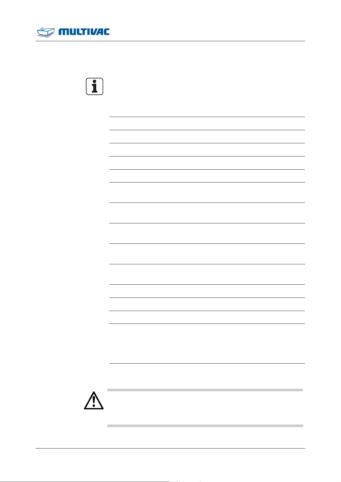
Shutdown, transport, storage
8 Shutdown, transport, storage
Info
Observe the safety instructions, see Section 1 "S
8.1 Shutting down the machine
AFETY".
¾ Remove film from the machine.
¾ Perform intensive cleaning of the machine.
¾ Drain the cooling water circuit.
¾ Close and disconnect the supply lines.
¾ Preserve the machine.
8.1.1 Cleaning the machine
¾ Perform intensive cleaning of the machine, see Section 5.2
"CLEANING THE MACHINE".
8.1.2 Preserving the machine
¾ Preserving the machine, see Section 5.1.7 "CORROSION PROTEC-
TION AND LUBRICATION".
8.1.3 Closing and disconnecting supply lines
¾ Close lid.
¾ Lock lid in place.
¾ Disconnect the machine from the mains electricity.
8.2 Transporting the machine
8.2.1 Transporting the machine
WARNING
¾ Wear personal protective equipment.
Injury hazard!
The machine is heavy.
Carrying the machine can cause injuries.
¾ Have a second person assist you.
11.06.2014 75
Page 76

Shutdown, transport, storage
Transporting the machine
NOTICE Danger of material damage!
At an inclination of more than 15°, the oil in the vacuum pump
shifts.
The air de-oiling elements will get wet from the oil and become ineffective. This will damage the vacuum pump.
¾ Transport and set the machine down as horizontally as possi-
ble.
¾ Do NOT tilt the machine.
¾ Carefully raise the machine.
¾ For machine dimensions and weight, see "Technical specifica-
tions".
¾ Transporting the machine
¾ Avoid severe jolts.
8.3 Storing the machine
¾ Observe the ambient conditions for storing the machine, see
¾ Ensure that the location site is of adequate load-bearing capac-
¾ Shutting down the machine.
¾ Select a suitable storage site.
"Technical specifications".
ity and keep the weight of the unit in mind, see "Technical
specifications".
¾ If necessary, cover the machine with film.
76 11.06.2014
Page 77
Disposal
9 Disposal
9.1 Disposing of the machine
Info
• Sealing bars can be reused on other machines of the same series.
• If disposal of the machine is not handled by the manufacturer,
dispose of the machine as described below.
¾ Disconnect the machine from the mains electricity, see Section
8.1.3 "CLOSING AND DISCONNECTING SUPPLY LINES ".
¾ Dispose of the materials properly, observing all legal and com-
pany-internal regulations regarding environmental protection.
9.2 Dispose of operating materials
9.2.1 Disposing of oil and grease
NOTICE Protect the environment!
Operating materials and working equipment are environmentally
harmful.
Improper disposal is harmful to the environment.
¾ Handle operating materials and working equipment properly.
¾ Dispose of operating materials and working equipment at suit-
able collection points.
¾ Observe the environmental directives.
¾ Handle operating materials and working equipment properly and
dispose of them in a professional manner.
Info
Excerpt from the disposal directive:
• It is prohibited to mix used oil with other waste.
• Used oils may NOT be mixed with each other.
• Used oil filters should be collected, stored, transported and disposed of separately from other waste.
11.06.2014 77
Page 78
Disposal
Dispose of operating materials
9.2.2 Disposing of packaging materials
Info
Packaging materials are resource materials that can be recycled.
• Improper disposal is harmful to the environment.
• Films should be collected for recycling.
• Follow the disposal instructions of the packaging material manu-
¾ Handle packaging materials properly and dispose of them in a
Info
Packaging materials are resource materials that can be recycled.
• Improper disposal is harmful to the environment.
• Films should be collected for recycling.
• Follow the disposal instructions of the packaging material manu-
facturer.
professional manner.
facturer.
9.2.3 Dispose of chemicals
Chemical burn hazard!
Cleansers are caustic. Caustic effects are NOT noticed immedi-
WARNING
WARNING
ately.
Contact with the skin can cause burns.
¾ Wear the prescribed personal protective equipment when han-
dling cleansers.
¾ Observe the manufacturer's instructions.
Fire hazard!
Alcohol-based disinfectants are highly flammable.
Fire, naked light or smoking ignites the disinfectant and can thus
cause fires.
¾ When disinfecting the machine, flames or naked lights are pro-
hibited.
¾ Smoking is prohibited.
¾ Observe the instructions of the disinfectant manufacturer.
¾ Handle cleansers and disinfectants properly and dispose of them
in a professional manner.
78 11.06.2014
Page 79

Disposal
Dispose of operating materials
Info
Improper disposal is harmful to the environment.
• Observe the safety data sheets of the cleanser and disinfectant
manufacturers.
• Follow the disposal instructions of the cleanser and disinfectant
manufacturers.
• Observe regionally applicable disposal regulations.
11.06.2014 79
Page 80
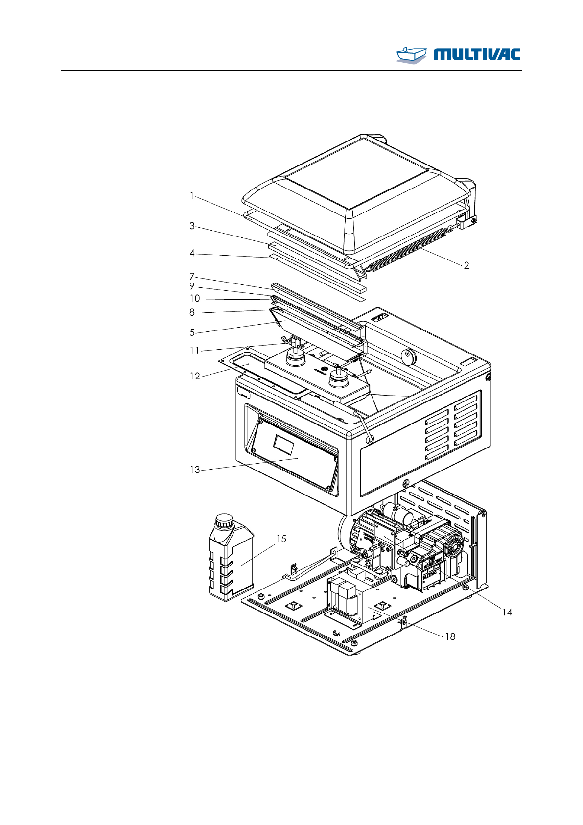
Spare parts
10 Spare parts
Fig. 30: Spare parts drawing
80 11.06.2014
Page 81
Spare parts
Item Material number Designation Quan-
tity and
unit of
measurement
1 105893127 Round cord (chamber lid gas-
1.6 m
ket)
2 105003538 Tension spring 1 pc.
3 81863151040 Profile thread 0.32 m
4 81848121000 Teflon tape 0.13 mm x 16 mm 0.32 m
5 105409738 Sealing bar, complete 1 pc.
6 11131117143 Repair kit for sealing bar (con-
1 pc.
tains items 4, 7, 8, 9)
7 81848121006 Teflon tape 0.13 mm x 40 mm 0.39 m
8 81848121001 Teflon tape 0.25 mm x 16 mm 0.43 m
9 85662801000 Vacromium tape (heating tape
0.47 m
3 mm)
10 85662802090 Round wire 0.47 m
11 85123126101 Contact bushing 2 pc.
12 11181798100 Diaphragm 1 pc.
13 105326253 Control 1 pc.
14 11181798040 Diaphragm 1 pc.
15 105048117 Low odour synthetic oil for vac-
1 l
uum pumps (food grade)
15 91111114013 HD mineral oil (not food grade) 1 l
16 105865634 Air de-oiling element for vac-
1 pc.
uum pump model R5 KB
0010D
16 106003423 Gasket set (filter) for VP8 vac-
1 pc.
uum pump
17 106003425 Set of consumable parts for
1 pc.
VP8 vacuum pump (including
item 16)
18 85641281113 Transformer 220_240/20 volt 1 pc.
18 85641281114 Transformer 110/20 volt 1 pc.
11.06.2014 81
Page 82

Glossary
Glossary
Automatic
Automatic sensitivity
Cooling down Sealing
If the function Automatic is set, the machine will reach the optimum
evacuation time and pressure depending on the product.
The automatic evacuation is suitable for the following cases:
• Achieving the best possible vacuum for long shelf life.
• Packing of products for which the optimum evacuation pressure
is not known.
• Packing of the same product but one which has varying properties (e.g. varying moisture content, varying temperature).
If the evacuation is automatic the value for Automatic sensitivity can
be adapted to the product.
Determines the evacuation time and the evacuation pressure
reached when evacuating with the Automatic function. The sensitivity is adjustable from 1 to 10. The lower the sensitivity, the lower the
evacuation pressure reached. The value for Automatic sensitivity is
dependant on the product.
High value for Automatic sensitivity (value 10):
• Is suitable for very moist or fluid products.
• Evacuation process ends early.
• Evacuation pressure reached in the pack is high.
Low value for Automatic sensitivity (value 1):
• Is suitable for dry products.
• Evacuation process ends late.
• Evacuation pressure reached in the pack is low.
Value for the cooling down time of the seal seam. The vacuum in the
chamber and the sealing pressure are maintained for this length of
time. The seal seam can harden. The sealing is switched off during
this time.
Cycle time
Delayed ventilation -
The display contains the times of the individual procedures of the
last packaging procedure.
The ventilation of the chamber begins with a delay after sealing.
Sealing
Distribution time evacuation
Switching interval between the completed evacuation process and
the beginning of the gas flushing process. During the distribution
time remaining air pockets in the products can escape before the
package is sealed.
Distribution time - Gas
flushing
82 11.06.2014
Switching interval after the gas flushing process, during which the
gas can distribute itself in the the film pouch.
Page 83

Evacuation pressure
Fill diaphragm
Gas flushing pressure
Glossary
Is the pressure to which the film pouch and the chamber are evacuated. The pressure is measured in the chamber.
Evacuation to a pre-determined pressure is suitable for the following
cases:
• Achieving a package result which is different from that of the optimum evacuation pressure.
• Packing of products for which the optimum evacuation pressure
is known.
• Packing of the same product which has identical properties.
During this time sealing pressure is applied to the sealing diaphragm.
Indicates the pressure until the film pouch is filled with inert gas.
Pressure is measured in the chamber.
Gas flushing time
Hours of operation
Machine cycles
MCV duration
MCV threshold
Post-evacuation time
Rinsing time, gas
flushing
Sealing time
Indicates the amount of time for which the film pouch will be filled
with inert gas. Pressure is not influenced by this.
Shows the time the machine has been operating. The counter begins to count as soon as the machine is switched on and can not be
reset.
Counts the number of complete machine cycles. The counter can be
modified and reset. It is used to control the quantities produced.
During this time the set vacuum is maintained during the MCV process (Pressure value + threshold).
If the pressure value set here is exceeded during the MCV process,
further evacuation automatically takes place.
This time extends the evacuation process. Through this, the reached
evacuation pressure is lower than the set value. This time begins,
when the set pressure is reached. Suitable for damp products.
During this time the vacuum valve and gas valve are opened simultaneously. On one side of the chamber a vacuum is created, on the
other side gas is supplied. The film pouch is thoroughly flushed with
gas. This reduces the residual oxygen content.
During this time the film pouch is sealed. The sealing time depends
on the material and the thickness of the film pouch.
Sealing time max
Settings - Production
Data
total cycles
This time determines the maximum value for the sealing time.
Shows all currently set target values.
Shows the completed machine cycles.
11.06.2014 83
Page 84

Glossary
Vacuum pump - Production data
Counts the vacuum pump's hours of operation. Counting starts as
soon as the vacuum pump is turned on. The display cannot be
changed.
Vacuum test
Ventilate diaphragm
Automatic leakage test of the vacuum system and the sealing diaphragm.
During this time the sealing diaphragm is evacuated. The sealing is
without sealing pressure.
84 11.06.2014
Page 85

Index
A
Access authorisations, selecting 42
Access right 42
Access right, resetting 42
Access rights 30
Access, blocking 42
Against regulations 13
Air de-oiling element 36, 76
Air humidity 34
Airtightness testing 32
Ambient conditions 34
Ambient temperature 34
Anti-corrosion agents 52
Automatic 82
Automatic evacuation 82
Automatic sensitivity 82
B
Basic cleaning 37
Basic settings 46
Buying source 61
C
Calling up menus 41
Care products table 60
Chamber 24
Chamber lid 24
Chamber lid gasket 24
Chamber size 34
Change password 43
Cleaning 53
Cleaning device 52
Cleansers 50
Configuration code 27
Control terminal 24, 26
Cooling down Sealing 82
Corrosion protection 52
Counter-pressure bar 24
Cycle time 82
D
Daily cleaning, performing 53
Delayed ventilation - sealing 82
Depth 34
Diagnostic display 29
Diagnostic message 72
Diagnostic message, acknowledging 27
Index
Diagnostic number 29
Dimensions 33
Disinfectant 51
Disinfection 53
Display 27
Display cycle time 47
Display hours of operation 47
Display production data 47
Display total cycles 47
Display, setting 48
Disposal directive 77
Dispose of chemicals 78
Disposing of the machine 77
Distribution time - evacuation 82
Distribution time - gas flushing 82
Drying packaging 32
E
EMC 13
Entering basic settings 46
Error 29
Error number 29
Evacuation Pressure 83
Evacuation process, cancelling 27
Evacuation, automatic 82
F
Factory setting 44
Fill diaphragm 83
Film, disposal 78
G
Gas flushing pressure 83
Gas flushing time 83
Gas purging 83
Gas supply 16
Grease disposal 77
H
Hazards, avoiding 15
Height 33, 34
High-pressure cleaners 50
Hygiene 17
Hygiene standard 17
I
Incorrect use 13
Information labels 21
11.06.2014 85
Page 86

Index
Inputs, sealing 46
Installation conditions 34
Installation location 15
Instructions to follow 8
Intended use 12
Intensive cleaning, performing 58
IT network 16
K
Key 26
L
Label 21
Language selection 43
Load recipe 44
Load recipe quickly 44
Lock 28
Locking for lid 24
Login 42
Low-pressure test 18
M
Machine control 26
Machine cycles 83
Machine cycles, modifying 46
Machine cycles, resetting 46
Machine labels 21
Machine shutdown 75, 76
Machine storage 76
Machine, cleaning 53
Machine, disinfecting 53
Machine, monitoring 14
Machine, switching off 38
Machine, switching on 38
Machine, transporting 75
Machine's hours of operation 47
Mains voltage 33, 37
Malfunctions 72, 73
Manufacture of spare parts 11
Max. pre-fuse 33
Max. short-circuit current 33
MCV 32
MCV Duration 83
MCV threshold 83
Measurement of residual oxygen 18
Menu tree 31
Misuse 13
Modifications 11
Monitoring obligation 14
N
Noise exposure 35
Nominal current 33
Nominal power 33
Non-ionising radiation 13
O
Oil disposal 77
Oil level 71
Oil sight glass 25
Oil, adding 68
Oil, changing 67
Oil, draining 67
Operating company, obligation 14
Operating directive, creating 14
Operating electrical circuit 16
Operating height 34
Operating hours 83
Operating materials 77
P
Pack, checking 18
Packaging process 32
Packing products 39
Parameters, setting 42
Password 42
Performing daily disinfection 53
Personal protective equipment 15
Personnel, training 15
Phases 33
Post evacuation time 83
Power supply 16
Power supply connection 25, 33
Power supply, connecting 37
Pre-fuse 33
Preset recipes 32
Pressure equipment, testing 19
Process sequence 31
Production data 83
Program 44
Protection type 33
Protective equipment 15
Pump protection function 19
Purging time gas flushing 83
R
Reasonably foreseeable incorrect use 13
Recipe 44
Recipe keys 44
Recipe, deleting 45
Recipe, saving 45
86 11.06.2014
Page 87

Recipes 32
Recommended maintenance 63
Relative air humidity 34
Requirements, gas supply 16
Reset password 43
Residual current protective device 16
Residual risks 14
S
Safety devices 19, 20
Safety instructions 9
Safety labels 21
Scope of delivery 6
Screw plug, drain opening 25
Seal seam strength 18
Seal seam width 18
Sealing 46
Sealing bar 24
Sealing bar, installing 66
Sealing bar, removing 66
Sealing bar, replacing 66
Sealing length 34
Sealing procedure, cancelling 27
Sealing time 83
Sealing time max 83
Sealing, setting 46
Select process 45
Selection of personnel 15
Sensitivity 82
Set MCV 46
Set process 45
Set standard 45
Setting up the machine 36
Settings - Production data 83
Short-circuit current 33
Show settings 47
Software version 27, 38
Spare parts 80
Stacking test 18
Index
Standard process 32
Startup display 27
Status display 28
Steam jets 50
Storage temperature 34
Storage test 18
Supply lines, closing 75
Supply lines, disconnecting 75
Symbols 7
T
Target group 9
Target values 83
Technical data 33
Technical products 32
Testing procedure 18
Third-party part 14
TN-S network 16
Total cycles 47, 83
Transport 75
Transport equipment 75
Troubleshooting 72
Type designation of machine control 27
V
Vacuum pump 34, 36, 76
Vacuum pump - production data 84
Vacuum pump hours of operation 47
Vacuum test 84
Vacuum test, performing 65
Values, changing 42
Ventilate diaphragm 84
Visual inspection 62, 63
W
Warnings 7
Weight 34
Width 34
Working equipment 77
11.06.2014 87
Page 88

MULTIVAC branch offices
MULTIVAC branch offices
GERMANY
MULTIVAC Sepp Haggenmüller GmbH & Co. KG
Tel.: +49 83 34 601 0
Fax:+49 83 34 601 199
[email protected]
www.multivac.com
SWITZERLAND
MULTIVAC EXPORT AG
Tel.: +41 41 785 65 65
Fax:+41 41 785 65 10
[email protected]
www.multivac.com
GERMANY
MULTIVAC Marking & Inspection GmbH & Co. KG
Tel.: +49 5224 931-0
Fax:+49 5224 931-299
[email protected]
www.multivac.de
AUSTRALIA
MULTIVAC Australia PTY.
LTD.
Tel.: +61 3 8331 2800
Fax:+61 3 8331 2810
[email protected]
www.multivac.com
BULGARIA
MULTIVAC Bulgaria EOOD
Tel.: +359 2 988-55-00
Fax:+359 2 988-55-88
[email protected]
www.multivac.bg
GERMANY
MULTIVAC Resale & Service
GmbH
Tel.: +49 2157 8197 0
Fax:+49 2157 8197 22
[email protected]
www.multivac.de
BELGIUM
Multivac N.V.
Tel.: +32 15 569 50 9
Fax:+32 15 569 50 1
[email protected]
www.multivac.com
CHILE
MULTIVAC CHILE S.A.
Tel.: +56 27 996 00 0
Fax:+56 27 996 00 1
[email protected]
www.multivac.com
ARGENTINA
MULTIVAC Argentina S.A.
Tel.: +54 11 4723 3766
Fax:+54 11 4723 4098
[email protected]
www.multivac.com
BRAZIL
MULTIVAC do Brasil
Tel.: +55 19 3795-0818
Fax:
[email protected]
www.multivac.com
CHINA
MULTIVAC (Shanghai) Trading
Co.
Building 7, Lane 195, Qianpu
Road (Shanghai)
Tel.: +86 21 3701 8118
Fax:+86 21 3766 0051
[email protected]
www.multivac.cn
DENMARK
MULTIVAC A/S
Tel.: +45 75 853 42 2
Fax:+45 75 853 45 4
[email protected]
www.multivac.com
88 11.06.2014
ESTONIA
MULTIVAC Oy Estonia Branch
Tel.: +372 622 8258
Fax:+372 622 8259
[email protected]
www.multivac.com
FINLAND
MULTIVAC Oy
Tel.: +358 20 792 13 00
Fax:+358 20 792 13 71
[email protected]
www.multivac.com
Page 89

MULTIVAC branch offices
FRANCE
MULTIVAC FRANCE S.A.S.
Tel.: +33 16 412 13 14
Fax:+33 16 412 75 30
[email protected]
www.multivac.com
INDIA
MULTIVAC Laraon India Private Limited
Tel.: +91 12 446 10 000
Fax:
[email protected]
www.multivac.com
ITALY
MULTIVAC Italia Service
S.R.L.
Tel.: +39 02 450 32 08
Fax:+39 02 458 63 819
[email protected]
www.multivac.com
GREECE
MULTIVAC Hellas Mepe
Tel.: +30 21 066 19 621
Tel.: +30 21 066 19 622
Fax:+30 21 066 19 662
[email protected]
www.multivac.com
IRELAND
MULTIVAC Ireland Ltd.
Tel.: +353 (0) 1 4133200
Fax:+353 (0) 1 4133205
www.multivac.com
JAPAN
Tokyo Foods Machinery Co.
Ltd.
Tel.: +81 33 663 40 06
Fax:+81 33 662 49 41
[email protected]
www.multivac.com
GREAT BRITAIN
MULTIVAC UK Ltd.
Tel.: +44 1793 425800
Fax:+44 1793 616219
[email protected]
www.multivac.com
ISRAEL
MULTIVAC B.P.S. Ltd.
Tel.: +972 46 344 68 1
Fax:+972 46 344 67 8
[email protected]
il.multivac.com
CANADA
MULTIVAC Canada Inc.
Tel.: +1 905 264 1170
Fax:+1 905 264 9647
[email protected]
www.multivac.com
COLUMBIA
Corporación MULTIVAC
S.A.S. Oficinas
Tel.: +57 1 547 5241
Fax:+57 1 547 4276
[email protected]
www.multivac.com
LITHUANIA
MULTIVAC Oy filialas
Bukiškės
Tel.: +370 52 105 03 6
Fax:+370 52 336 41 3
[email protected]
www.multivac.com
NETHERLANDS
MULTIVAC BV
Tel.: (+31) 0348 436570
Fax:(+31) 0348 436580
[email protected]
www.multivac.com
CROATIA
MULTIVAC d.o.o.
Tel.: +385 14 855 20 5
Fax:+385 14 855 20 4
[email protected]
www.multivac.com
MEXICO
MULTIVAC Mexico S.A. de
C.V.
Tel.: +52 55 502 05 555
Fax:+52 55 502 05 560
[email protected]
www.multivac.com
NORTH AFRICA
MULTIVAC Afrique du Nord
Tel.: +216 71 963 963
Tel.: +216 71 860 128
Fax:+216 71 860 230
[email protected]
www.multivac.com
LATVIA
MULTIVAC Oy Latvia Branch
Tel.: +371 67 623 121
Fax:+371 67 622 602
[email protected]
www.multivac.com
NEW ZEALAND
MULTIVAC New Zealand Ltd.
Tel.: +64 9 238-3055
Tel.: +64 2 146-0807
Fax:+64 9 238-3054
[email protected]
www.multivac.com
NORWAY
MULTIVAC AS
Tel.: +47 33 445 25 0
Fax:+47 33 445 25 1
[email protected]
www.multivac.com
11.06.2014 89
Page 90

MULTIVAC branch offices
AUSTRIA
MULTIVAC Vertriebsgesellschaft mbH
Tel.: +43 (0)1 698 1300
Fax:+43 (0)1 698 1300-99
[email protected]
www.multivac.com
ROMANIA
MULTIVAC Romania S.R.L
Tel.: +40 21 345 34 61
Fax:+40 21 345 34 61
[email protected]
www.multivac.com
SERBIA
MULTIVAC d.o.o.
Tel.: +381 21 4721 144
Fax:+381 21 4721 146
[email protected]
www.multivac.com
POLAND
MULTIVAC Sp. z o. o.
Tel.: +48 81 746 67 00
Fax:+48 81 746 67 01
[email protected]
www.multivac.com
RUSSIA
MULTIVAC Rus / Moscow
127254 Moscow
Tel.: +7 495 604 4902
Fax:+7 495 604 4903
[email protected]
www.multivac.com
SINGAPORE
MULTIVAC Pte. Ltd.
Tel.: +65 6565 3919
Fax:+65 6566 9798
[email protected]
www.multivac.com
PORTUGAL
Multi Vacuo - Sistemas de Embalagens Lda.
Tel.: +351 21 41 95 541
Tel.: +351 93 77 74 355
Fax:+351 21 41 95 543
[email protected]
www.multivac.com
SWEDEN
MULTIVAC Sverige
Tel.: +46 311 70 0
Fax:+46 150 30 0
[email protected]
www.multivac.com
SLOVAKIA
MULTIVAC Export AG organizačná zložka Slovakia Ges.m.b.H
& Co. KG
Tel.: +421 24 446 40 70
Fax:+421 24 446 40 72
[email protected]
www.multivac.com
SPAIN
MULTIVAC Packaging Systems España, S.L.
E - 08396 Sant Cebrià de
Vallalta (Barcelona)
Tel.: +34 902 290 909
Fax:+34 937 632 517
[email protected]
www.multivac.com
CZECH REPUBLIC
MULTIVAC Packing Machines, Ceska Republika
S.R.O.
Tel.: +420 26 126 05 16
Fax:+420 26 126 05 18
[email protected]
www.multivac.com
SOUTH AFRICA
MULTIVAC Southern Africa
PTY. (LTD.)
Tel.: +27 16 340 5800
Fax:+27 16 340 5819
[email protected]
www.multivac.com
TURKEY
MULTIVAC Ambalaj Makineleri
San. ve Tic. A.Ş.
Tel.: +90 216 526 00 33
Fax:+90 216 526 03 83
[email protected]
www.multivac.com
SOUTH KOREA
MULTIVAC KOREA CO., LTD
Tel.: +82-70-4895-4041
Fax:+82-70-8244-4050
[email protected]
www.multivac.com
UKRAINE
MULTIVAC Ukraine LLC
Tel.: +380 44 499 90 70
Fax:+380 44 499 90 67
[email protected]
www.multivac.com
90 11.06.2014
Page 91

MULTIVAC branch offices
HUNGARY
MULTIVAC Hungária Kft.
Tel.: +36 23 500 28 7
Fax:+36 23 500 28 8
[email protected]
www.multivac.com
USA
MULTIVAC, Inc.
Tel.: +800 877 5200
Tel.: +1 816 891 0555
Fax:+800 347 6164
Fax:+1 816 891 0622
[email protected]
www.multivac.com
UNITED ARAB EMIRATES
MULTIVAC Middle East (FZE),
Amir Sotoudeh
Tel.: +971 4 299 1980
Fax:+971 4 299 1981
[email protected]
www.multivac.com
11.06.2014 91
 Loading...