

Multiva Optima T500 Optima T600, Optima T800, Optima T900, Optima T700, Optima T Maintance Manual
...
Optima
Starting from serial nr 05240016
01 / 2016
O
O
O
P
P
P
E
E
E
R
R
R
A
A
A
T
T
T
I
I
I
O
O
O
N
N
N
A
A
A
N
N
N
D
D
D
M
M
M
A
A
A
I
I
I
N
N
N
T
T
T
E
E
E
N
N
N
A
A
A
N
N
N
C
C
C
E
E
E
M
M
M
A
A
A
N
N
N
U
U
U
A
A
A
L
L
L
S-TINE HARROWS


Contents
1. FOREWORD ............................................................................................................................................................................ 1
1.1. Intended use of the machine ...................................................................................................................................... 1
1.2. Technical specifications ................................................................................................................................................. 2
1.3. Type plate ........................................................................................................................................................................... 2
2. SAFETY INSTRUCTIONS ...................................................................................................................................................... 3
2.1. Warning symbols ............................................................................................................................................................. 3
2.2. Hitching and unhitching ............................................................................................................................................... 4
2.3. Transport on public roads ............................................................................................................................................ 4
2.4. Using the harrow ............................................................................................................................................................. 5
2.5. Maintenance ...................................................................................................................................................................... 6
3. COMMISSIONING AND BASIC ADJUSTMENTS ........................................................................................................... 7
3.1. Measures before commissioning ............................................................................................................................... 7
3.2. Hitching to tractor ........................................................................................................................................................... 7
3.3. Adjusting hydraulic hoses ............................................................................................................................................ 8
3.4. Side section and front levelling board hydraulics selector valve, Optima T500 - T700 .......................... 8
3.5. Operating principle of the front levelling board and depth adjustment hydraulics .............................. 9
3.6. Synchronizing the cylinders......................................................................................................................................... 9
3.7. Harrow position adjustment..................................................................................................................................... 10
3.8. Basic adjustment of the side sections ................................................................................................................... 10
4. USE AND ADJUSTMENT OF THE HARROW............................................................................................................... 12
4.1. Seedbed preparation .................................................................................................................................................. 12
4.2. Tillage technique .......................................................................................................................................................... 12
4.3. Starting and setting into work position ................................................................................................................ 13
4.4. Transport position ........................................................................................................................................................ 13
4.5. Adjusting working depth ........................................................................................................................................... 14
4.6. Adjusting the depth scale .......................................................................................................................................... 14
4.7. Using the levelling boards ......................................................................................................................................... 15
4.8. Using the rear harrow ................................................................................................................................................. 16
4.9. Using the cage roller .................................................................................................................................................... 17
4.10. Front support wheel ( T1000 – T1500 only) ..................................................................................................... 17
5. MAINTENANCE .................................................................................................................................................................. 18
5.1. Wear parts ....................................................................................................................................................................... 18
5.2. Changing a wheel ......................................................................................................................................................... 18
6. MAINTENANCE PROGRAMME, INSPECTIONS ......................................................................................................... 19
6.1. Bolt tightening torques .............................................................................................................................................. 19
6.2. Tyre pressure .................................................................................................................................................................. 19
6.3. Wheel hub bearing clearance .................................................................................................................................. 20
6.4. Bogie bearing clearance ............................................................................................................................................. 20
6.5. Hydraulics ........................................................................................................................................................................ 20
6.6. Side section locking ..................................................................................................................................................... 21
6.7. Front support wheel bearing clearance ............................................................................................................... 21
6.8. Selector valve operation ............................................................................................................................................ 22
7. MAINTENANCE PROGRAMME, LUBRICATION......................................................................................................... 23
8. STORAGE .............................................................................................................................................................................. 27

9. WARRANTY.......................................................................................................................................................................... 28
Appendix 1. EC DECLARATION OF CONFORMITY ........................................................................................................ 29
Appendix 2. Hydraulic schematic Optima T500............................................................................................................. 30
Appendix 3. Hydraulic schematic Optima T600-700 .................................................................................................... 31
Appendix 4. Hydraulic schematic Optima T800-900 .................................................................................................... 32
Appendix 5. Hydraulic schematic Optima T1000 .......................................................................................................... 33
Appendix 6. Hydraulic schematic Optima T1250 .......................................................................................................... 34
Appendix 7. Hydraulic schematic Optima T1500 .......................................................................................................... 35
Appendix 8. Connection socket according to SFS 2473 .............................................................................................. 37

1
1. FOREWORD
Multiva agricultural machines are manufactured in Finland. The modern production technology,
excellent raw materials and careful manufacturing and finishing utilised in the production of the
machines guarantees a high quality product. Multiva product range includes the following agricultural
machines:
• Trailers
• S-Tine Harrows
• Disc Harrows
• Cultivators
We thank you for choosing and putting your trust on the Multiva S-Tine Harrow. We hope that the
product fulfils you requirements and serves you for a long time. We advise you to carefully go
through these instructions before commissioning the machine. The inspection and maintenance
activities described in these instructions are vitally important for the proper functioning of the machine
and the validity of the warranty.
All instructions, warnings and cautions must be followed without exception. They are given to ensure
the safety of the user and the durability of the machine.
These operation and maintenance instructions apply to Optima range harrows starting from serial
number 05240016.
1.1. Intended use of the machine
Multiva s-tine harrow is designed to perform seedbed preparation of soil, to which primary tillage has
already been carried out, to prepare the soil for seeding. Multiva s-tine harrow produces a smooth
seedbed and a sufficiently fine crumb structure, which are the requirements for even and optimal
growth, economically with a minimum amount of harrowing. The s-tine harrow, with two or three
levelling boards and narrower tine spacing, can also be used for levelling. Never use the s-tine harrow
to perform primary tillage to unprepared soil!
Multiva Optima T is an efficient harrow for various soil types. The spacious frame structure prevents even
extensive amounts of plant residue from causing harrow clogging. The supporting wheels ensure
uniform tillage depth even on soft soil types. Due to the great weight and robustness of the tines of the
harrow, it is also suitable for tilling heavy soil. The tilling power of Optima T models can be increased by
utilising a rear levelling board which is available as an option. The working width can be changed by
using extension parts in models T600 and T800. Extension parts are bolted to the base frame of the stine harrow.

2
1.2. Technical specifications
With standard equipment
Optima T
T500 T600 T700 T800 T900 T1000
T1250
T1500
Nr of s
-
tines
67 79 91 105 117 129
163 183
Tine spacing mm
75 75 75 75 75 75
75 75
Nr of tine axles
7 7 7 7 7 9 9 9
Working width cm
500 600 700 800 900 1000
1300
1450
Length of the frame
300 300 300 300 300 410
410 410
Transport width cm
300 340 340 340 340 420 420 420
Extension parts
- - 2x0,5m
- 2x0,5m
- - -
Power require
ment hp
80 100 120 140 160 200
260 300
Weight kg
2220
2700
3120
3540
3970
6530
7865
9820
Technical specifications can be found also on the manufacturer's website. Please contact the
manufacturer to acquire information about new products.
Due to ongoing product development, products and specifications discussed herein are subject
to change.
1.3. Type plate
A type plate similar to the one below is attached to the harrow. Please write all the information from the
type plate in this manual. When you are dealing with the supplier of the Multiva machine or a factory
representative, please mention the model and serial number of the machine. This is recommended to
avoid delays and unnecessary misunderstandings.
Fields in the type plate:
Serial = Serial number of the machine
Model = Model of the machine
Weight = Weight of the machine with standard
3
2. SAFETY INSTRUCTIONS
These safety instructions and safety distances must without exception be followed when using the
machine. The machine must be configured according to this manual and this manual must be utilised in
the operation and maintenance of the machine.
Never allow any person to ride the harrow during work or transport!
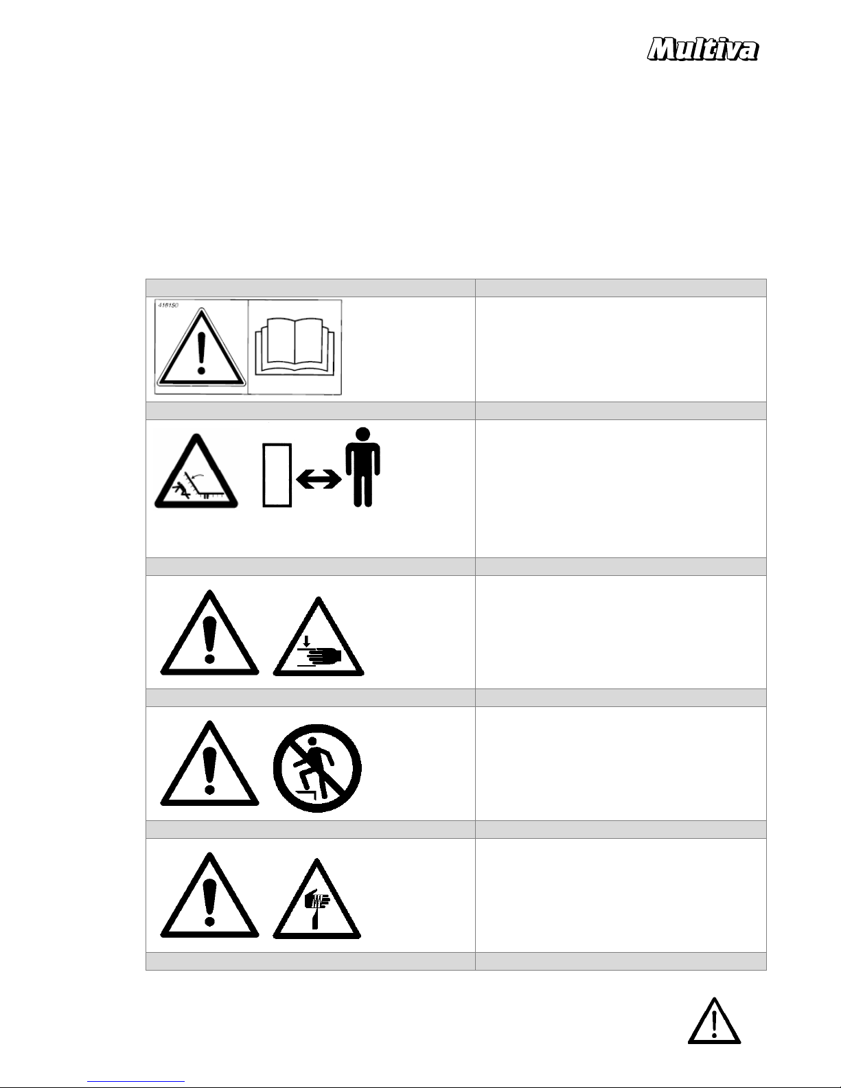
2.1. Warning symbols
Follow the warning labels attached to the harrow pictured below. Do not remove the warning labels on
the machine.
Warning label
Explanation
CAREFULLY READ THE OPERATION
MANUAL AND THE SAFETY INSTRUCTIONS
BEFORE CONNECTING THE MACHINE TO A
TRACTOR!
CRUSHING HAZARD!
IMPACT HAZARD!
Maintain a 10-metre safety distance from the
machine when the side wings are up and
when the machine is in operation.
Do not go under the machine unless it is
mechanically supported.
CRUSHING HAZARD!
There is a danger of crushing in hitching and
unhitching activities. Beware the bruising of
feet, fingers and arms
RISK OF FALLING!
Standing on the machine is not allowed in any
situation.
SHARP EDGES!
There is a risk of injury when using the
machine functions. Maintain a 10 m safety
distance when connecting the machine to the
tractor.
4
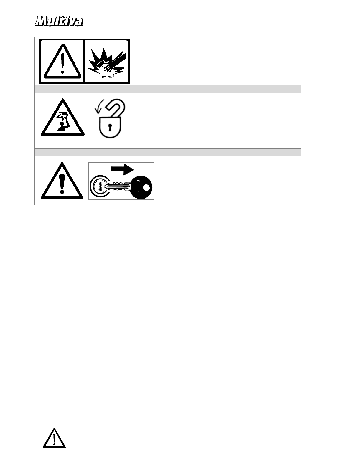
HIGH PRESSURE
HYDRAULIC OIL
!
Escaping hydraulic fluid under pressure can
penetrate the skin causing serious injury!
DANGER!
Proper function of the locking mechanisms
must be checked before any road transport;
Locking of the side wings and the ball valve for
the side wing hydraulics.
NOTE!
Turn off the tractor before making service or
adjustments to the machine.
Make sure that the tractor and machine won’t
move itself. Apply hand brake or wheel
wedges.
2.2. Hitching and unhitching
The harrow can only be hitched to the trailer hitch of the tractor. Follow all safety instructions
concerning the tractor when hitching or unhitching the harrow. There is a danger of crushing in
hitching and unhitching activities. Also beware the bruising of feet, fingers and arms. Do not disconnect
pressurised hydraulic connectors. When the harrow is hitched to the tractor, standing near the harrow,
and particularly its side sections, is forbidden.
2.3. Transport on public roads
When transporting the harrow on a public road, please take care and follow all orders under the Road
Traffic Act and special regulations concerning slow vehicles. Before moving, check the visibility of the
harrow's reflectors and the slow vehicle triangle as well as the functioning and visibility of the tractor's
lights. The reflectors, triangle and tractor lights must be maintained clean, as they affect the traffic
safety of the entire combination. When transporting the harrow, particular attention should be given on
the visibility of the rear turn signals. Always ensure that the harrow is sufficiently clean before transport
on public roads.
As standard, the harrow is fitted with reflectors at the extremities of the harrow to indicate the over
width portion of the towed machine. When driving on public roads, make sure that the lights of the
tractor are also visible from behind the harrow.
The maximum transport speed for the harrow with 300 tyres is 40 km/h and with 340 tyres 50
km/h.

5
1. Transport support pin
2. Spring cotter pin
The harrow has a transport support which prevents the machine lowering down accidentally in case of a
users fault or a sudden leak in the hydraulics. Transport support pin 1 must be set to its hole and locked
with pin 2 before any road transport.
Always before the road transport, make sure that the side wings have locked to the transport position.
Unintended opening of the wings should be prevented by closing the ball valve in the hydraulic hose.
Turn the lever crosswise to the hose. See section 4.4 in this manual.
2.4. Using the harrow
The operator must be familiar with the operation of the harrow and he/she must have the knowledge
and skills to operate the harrow correctly. The operator must study the operating instructions and
follow them.
The condition of the harrow, the tightness of the bolts and the tyre pressures must always be visually
checked before starting work. Never adjust or clean a moving harrow. During work, persons are
forbidden to ride the harrow or stand within the working area (safety distance 5 m). Safety distance
should also be kept while the harrow is not moving when the hydraulics is being used. Pressurised
hydraulic cables can release a deadly liquid spray. The side sections of the harrow can only be raised and
lowered when the harrow is not moving. When raising or lowering the side sections, ensure that no
persons are standing near the harrow. Before transport, ensure that the side sections are set to transport
position and locked. Before commencing working with the harrow, side sections must be fully lowered,
so that the cylinders are fully extended.
The side sections of the harrow should be raised and lowered by keeping the hydraulic pressure
continuously on during the whole movement. Interrupting the movement may disturb the function of a
valve in the system and the side sections will not move at the same time. Sudden change to the balance
may cause the harrow to tip over. This applies in particular 800 – 1500 harrows.

6
2.5. Maintenance
For maintenance, the harrow must be stopped and it must be blocked to stop it from moving.
Maintenance must be carried out on an even and stable surface to prevent the harrow from tipping
over or moving. Note the danger of slipping: Do not step on any part of the machine.
Maintenance-related and other measures should not be carried out when the harrow or one of its parts
is raised and unsupported.
When maintenance is carried out to the harrow, the side blocks must be lowered. In any event, ensure
safe working conditions and sufficient lighting. Turn off the tractor and release the pressure from the
hydraulics before handling any hydraulic hoses or components.
Only use original spare parts in the maintenance of the harrow. Using non-original spare parts will void
the warranty.

7
3. COMMISSIONING AND BASIC ADJUSTMENTS
3.1. Measures before commissioning
The sections of the harrow requiring lubrication have been lubricated at the factory and oil has been
driven to the cylinders during test runs. Still, it is recommended to review the lubrication points before
the first period of usage. Lubrication points are described in section 7 MAINTENACE PROGRAMME,
LUBRICATION.
3.2. Hitching to tractor
Attach the towing eye of the harrow's drawbar to the hydraulic tow hitch of the tractor. Note the safety
distance. Ensure that the hitch of the tractor locks on and that the hitch is not supported by the lifting
device.
Remember that pressurised hoses should never be handled and the hydraulics should be depressurised
before handling.
Hydraulic hoses are marked with colourful collars. Hoses are connected to dual purpose outputs.
Optima T500 - T700 :
The tractor must have 2 dual purpose hydraulic outputs.
The selector valve of the harrow directs the oil to the levelling board cylinders or the opening/closing
cylinders of the side sections depending on the height setting of the harrow. The operation of the
selector valve is described in section 3.4
Optima T800 - T1500
The tractor must have 3 dual purpose hydraulic outputs.
NB! All models: Ensure that the dual purpose valve used for height adjustment is actually set to
function as dual purpose and that the float position of the valve is not activated. If the float position
remains activated during height adjustment, this may result in the changing of the harrow's working
depth between sections during tillage!
NB! Optima T800 - T1000 : The raising cylinders of side sections must be connected to a hydraulic
output with a float position. The float position of the side section's raising cylinders must always be
activated during tillage. The float position allows the oil to flow freely in both hoses.
Adjust the pulling arms of the tractor to a height at which they do not become in contact with the
drawbar or hydraulic hoses during turning. When you unhitch the harrow from the tractor, remember to
also disconnect the hydraulic connectors.
Action
Marking the hose
Working depth
- down
1 x red
Working depth
- up 2 x red
Levell
ing board up / open side sections
1 x black
Levelling board down / close side sections
2 x black
Action
Marking the hose
Working depth
- down
1 x red
Working depth
- up 2 x red
Close side sections
1 x black
Open side sections
2 x black
Levelling board down
1 x blue
Levelling board up
2 x blue

8
3.3. Adjusting hydraulic hoses
After hitching the harrow to the tractor, adjust the hydraulic hoses between the hose rack and tractor to
a suitable length. The length of the hoses can be adjusted by loosening the hose rack lock (point 1 in
the illustration, x 3). Extra hose is left looped in the rack. Tighten the bolts after making the adjustment.
The length of the hoses is correct when the hoses do not become in contact with the tractor's pulling
arms during turning. The length of the hoses is too short if they tense up and disconnect from the
tractor's hydraulic connector during turning. The smallest allowed diameter for a hose loop is 200 mm.
If the diameter is too small, the loop must be opened and the hoses placed on the rack without looping.
If the loop is too small, there is a danger of breaking the hoses. Turn off the tractor and release the
pressure from the hydraulics before handling the hydraulic hoses
3.4. Side section and front levelling board hydraulics selector valve, Optima T500 - T700
In models Optima T500 - T700, the levelling board hydraulics and the side section hydraulics function
alternately using the same tractor valve, depending on the height adjustment of the machine. When
the harrow is raised up for transport, the selector valve in the frame of the machine directs the hydraulic
pressure to the lifting cylinders of the side sections. When the machine is in work position, the valve
directs the pressure to the levelling board cylinders. The valve operates automatically when the height
of the machine is adjusted between the work and transport positions. The selector valves are located in
front of the axles, in the centre section of the harrow and they are actuated from the axles through the
actuator arm.
Actuator arm of
the selector
Selector valve
9
Troubleshooting in the event that the side sections cannot be raised, Optima T500 - T700 :
Feel whether the pressure reaches the hoses of the side sections' lifting cylinders when the side sections
are raised.
• There is pressure -> Check that the hydraulic return connector is properly attached to the
tractor and that the hoses are not pinched anywhere. Quick connectors are not always
compatible with the tractor's connectors. Also test in another hydraulic return. Change another
quick connector to the hose.
• No pressure -> Lift the harrow up to the transport position. Check whether the selector valve
spindles are moving. The spindles can be moved manually by twisting their actuator bar. Check
whether the actuator bar of the selector valves is properly attached and that it is not kinked. If
the levelling board is working also when the harrow is raised up, the problem is that the
spindles of the selector valves have not moved.
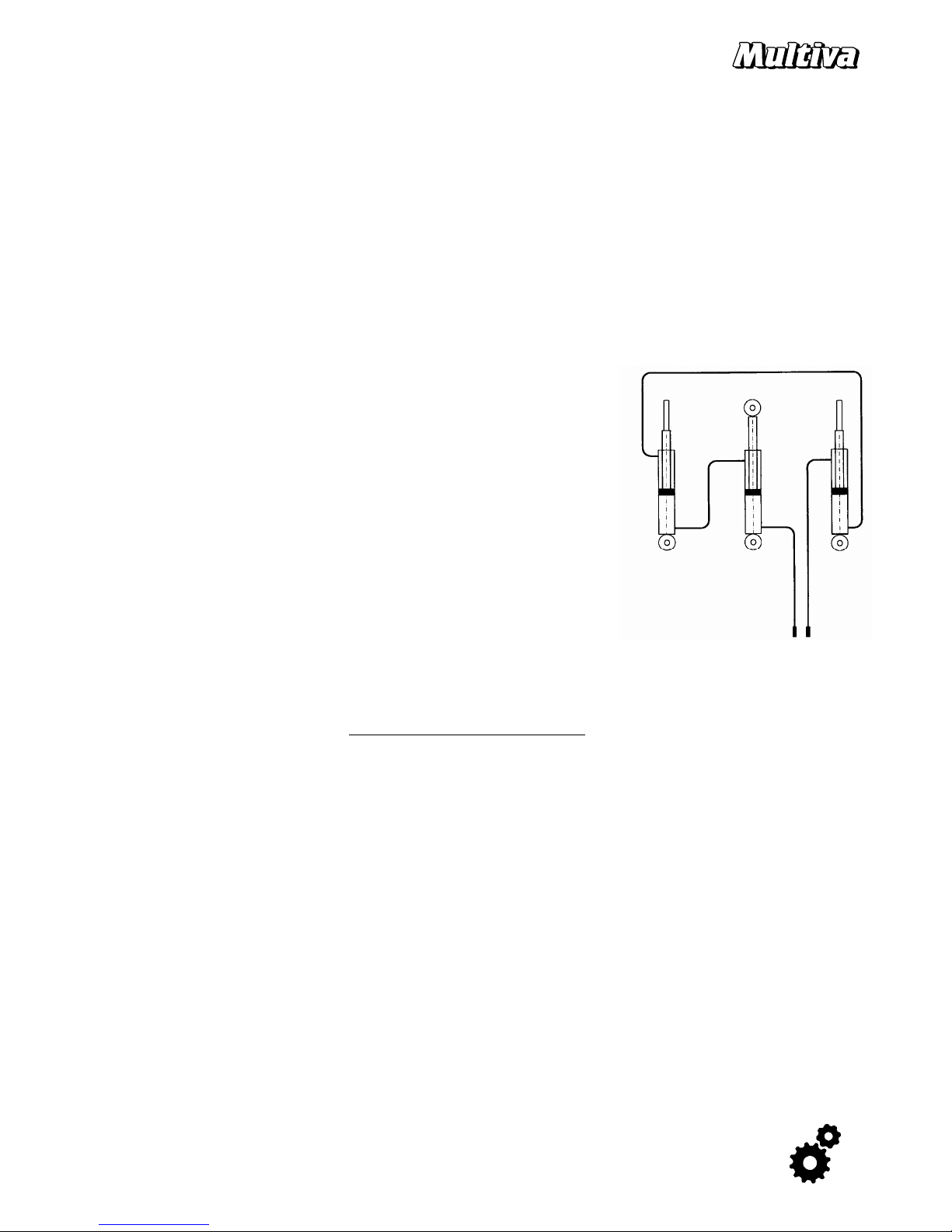
3.5. Operating principle of the front levelling board and depth adjustment hydraulics
The front levelling boards and the depth adjustment in models
equipped with fully hydraulic depth adjustment are operated by
three series-connected cylinders. The series-connection of
cylinders means that the oil flows from the piston side of one
cylinder to the rod side of the other cylinder. The oil only flows
through the tractor's valve to the first and last cylinder. All the
cylinders in the series are of different sizes, so that the oil volume
of the piston side corresponds to the volume of the next
cylinder’s rod side. Both the levelling board and depth
adjustment circuits have a double operated pilot valve that keeps
the working depth set even in the case that the valve of the
tractor leaks.
3.6. Synchronizing the cylinders
Series-connected cylinders must be set to the same level for them to work precisely.
Cylinders are synchronized by fully extending the cylinder rods using tractor hydraulics and maintaining
the pressure for about 30 seconds, and running the motor on low rpm. When the cylinder rod is fully
out, the oil can flow through a small opening past the piston to the next cylinder. Hydraulic oil flows
through all cylinders in the circuit, setting them to the same level and bleeding possible air out from the
system. Moving the cylinders back and forth will not synchronize them.
Synchronizing of depth and levelling board cylinders must always be carried out at the beginning of an
operation period. And always after changing a cylinder or a hydraulic hose to these circuits. Depth
adjustment cylinders must be synchronized at times also during tillage keeping the pressure on for a
few seconds.

10
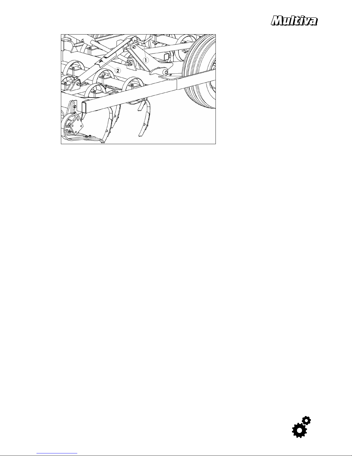
3.7. Harrow position adjustment
The horizontal position of the frame in relation to the vertical position is adjusted with the top link 1.
The adjustment ensures the even working depth of all tines. The position adjustment is tractor-specific
and depends on the height of the tractor's tow hitch. When the top link is shortened, the front end of
the frame lowers - correspondingly, lengthening the rod raises the front end. The top link must be
locked in place when the right position is found.
The adjustment must be checked during work as the tractor and the harrow may sink differently in the
field.
3.8. Basic adjustment of the side sections
The aim of the adjustment is to ensure that both side sections are at the same depth with regard to the
centre block. The factory adjustments must be checked when the machine is commissioned on the field.
NB! Before making adjustments, make sure that the depth cylinders are equalised and that the raising
cylinders of the side sections are not supporting the side sections.
The adjustment is performed by loosening the locking nut at the end of the cylinder (point 1). By
rotating the cylinder rod (point 2), you can adjust the depth of the side sections. By extending the
cylinder rod, the working depth of the side section decreases and by shortening it the working depth
increases. One rotation affects 5 mm to the cultivation depth.
Harrows
500 -
700 800 - 1500
Locking nut
key 36 mm
55 mm
Cyli
nder rod
key 24 mm
36 mm
11
Optima T500 and T550
Standard models with mechanical cranks for depth adjustment:
The centre section limiter pieces adjust the working depth similar to other models.
The working depth of side sections is always separately adjusted from the side section crank (point 1).
When the crank is turned, the working depth grows. One revolution of the side section adjustment
crank corresponds to one limiter piece in the depth adjustment of the centre section. The scale of the
side section depth adjustment can be moved to correspond to the depth scale of the centre section by
loosening the tightening bolt (point 2), 17 mm key.

12
4. USE AND ADJUSTMENT OF THE HARROW
Depending on the model of the harrow, some of the equipment mentioned in this manual are
installed as standard and some are available as options.
4.1. Seedbed preparation
The Multiva Optima T s-tine harrows are designed to perform seedbed preparation of soil, to which
primary tillage has already been carried out, to prepare the soil for seeding. The harrow is used to
loosen and crumble the soil to achieve a sufficiently fine result. The requirements for the even and
optimal growth of the cultivated plant include a seedbed that is as even as possible and the correct
surface crumb structure. An even seedbed is also important for the depth-holding of the seeder's
coulters.
The tillage effect is determined by changing the working depth, number of tillage rounds, number of
tillage times, tillage speed and directions as well as the tillage intensity of the levelling boards and cage
roller.
The correct tillage depth is the depth of sowing for the plant. On clay and silt soils, there must be a
sufficient amount of fine crumbs on top of the soil. This layer of crumbs forms a barrier against
evaporation, preventing the excessive drying of the soil. The surface of the seed layer must have larger
crumbs. They reduce the risk of slaking and maintain the seedbed loose. Particularly on silt soil, the
surface layer should not be tilled excessively fine. The primary objective of seedbed preparation of
easily cultivated sand, mull and peat soil is to level the soil for seeding.
In favourable conditions, the Multiva s-tine harrow may only need one tillage run. However, the number
of tillage passes must always be selected according to conditions. If several tillage passes are carried
out, the run directions should be made perpendicular to each other. This ensures the maximum
evenness of the seedbed.
The suitable tillage speed for the operation of the s-tine and rear harrow is, depending on the
conditions, 8 – 12 km/h. With excessive tillage speed, the tillage characteristics of the s-tine suffer.
NB! Optima T s-tine harrow should not be used for the primary tillage of unprepared soil.
4.2. Tillage technique
Suitable tillage technique is influenced by several factors, e.g. the size and form of the block and
direction of seeding. Correctly selected tillage technique reduces required work and ensures the best
possible result. If several tillage passes are made, the last pass should be performed in the intended
direction of seeding. This reduces unnecessary tilting of the seeder unit. If possible, it is recommended
to drive parallel to the longest side of the block to minimise the time spent on turning.
Turn the wide harrow smoothly or rise it up a bit when turning around at the end of a field strip.
Do not reverse the harrow while the tines are in the soil.

13
4.3. Starting and setting into work position
Raise the harrow to transport height. Ensure that the safety distance of the side sections is clear. Lower
the side sections. The lock pieces on the side sections open automatically. Maintain the hydraulics
actuated until the cylinders are fully extended.
1250 and 1500 models have valves that divide the oil to the outermost side sections. When opening the
wings, inner sections open first and then the outermost wings turn open. Outermost wings turn first
when setting the harrow to the transport position.
Before tillage, it is recommended to each time perform the synchronization of the front levelling boards
and depth adjustment as described in section 3.6. This ensures that the levelling board and working
depth cylinders operate accurately. When the synchronization is performed sufficiently often, the
hydraulics needs to be recirculated only for a few seconds. If you notice that the relative position of the
front levelling boards or the working depth adjustment has changed, the tractor must be stopped and
synchronization should be performed.
NB! Check the tightness of all bolts after 10 hours of tillage. In particular, the attaching bolts of s-tines or
levelling board tines may become loose during the first hectares.
4.4. Transport position
Raise the depth adjustment of the harrow to the
highest position. After this, raise the side sections
using the other valve to transport position. They lock
automatically with the locking piece springs (point
1). However, ensure that the locking piece has locked
the sections to top position before transport (point
2). If the sections are not locked, lower them slightly
and raise them again to top position.
When the sections are raised, the tractor valve must be activated until the lock piece of the side section
has without doubt risen up from the bottom position and locked the side sections up. Only after this
can the valve be left in hold position. Some of the tractor valves might produce such a high reaction
pressure that the force of the lock piece string may not be sufficient to lock the side sections. In this
case, the tractor valve should be set to float position and it should be simultaneously ensured that the
side sections actually lock.
Ensure that the harrow is sufficiently clean when you go to public roads.
14
4.5. Adjusting working depth
Working depth must always be measured from behind the harrow, from tilled soil and the harrow
should be adjusted according to each field block and the sown plant. The adjustment must be carried
out according to the hardest soil of the block. On softer areas, the working depth may be decreased
during tilling by using the depth adjustment hydraulics and the depth indicator.
The lowest working depth of the harrow is adjusted with the limiter pieces of the centre section
cylinder. Limiter pieces can limit the depth in steps of 5 mm. The harrow must be slightly raised up so
that the adjustment can be made. Note a danger of crushing. Turn off the tractor always before making
any adjustments.
NB!
Limiter pieces must be in either of the extreme positions, ie. either turned against the piston rod or
fully to the side.
4.6. Adjusting the depth scale
The scale under the limiter pieces can be adjusted to correspond to the actual working depth by
opening the wing nut located under the scale (point 1). After the adjusting, the scale is locked with the
wing nut.
The working depth indicator (in front of the harrow, in the centre) can be adjusted to show the true
depth in centimetres. After you have adjusted the harrow to desired depth, measure the true working
depth from the tilled soil behind the harrow. The scale is set to indicate the same working depth.
Loosen the locking bolt of the scale (point 2), using a 17 mm key, and turn the scale.

15
4.7. Using the levelling boards
The purpose of the levelling boards is to crush clods and even out the level changes of the surface of
the field. A correctly adjusted levelling board crushes and mills clods but does not gather a large wall of
soil in front. This also creates fuel savings as the excessive use of the levelling board requires a great
deal of power from the tractor.
Basic adjustment:
The rod of the harrow cylinders is threaded so that the sections can be adjusted to the same position.
The adjustment is carried out by loosening the lock nut (36 mm key) and rotating the piston rod (point
2, 24 mm key). Lengthening the rod raises the front levelling board and shortening it lowers the board.
Before making any adjustments, we recommend to tillage for a while and synchronize the levelling
board. This ensures that the misalignment of the levelling boards is not caused by the differences
between the cylinders.
Basic height adjustment:
Changing the height level can be done by opening two bolts from each attachment brackets (point 1
above). With the high position, the front levelling board is more vertical and it breaks, for instance,
slaked surface better. With the low position, the levelling board mills the clods smaller more efficiently.
Factory setting is at the high position. It is recommended for almost all conditions. Lower position can
be considered on very shallow cultivation.
Basic height levels of the front levelling board. Low – high.

16
The relation between the front and rear levelling boards in Optima T harrows can be quickly changed by
using the crank adjustment at the back end of the harrow. The adjustment position can be seen from
the scale.
4.8. Using the rear harrow
The purpose of the rear harrow is to even out the ridges caused by the s-tine harrow and to sort out the
soil material in the tilled layer. The rear harrow sorts out the small crumbs to the bottom of the tilled
layer and moves the large ones to the surface. As a result, the tilled layer does not evaporate the
moisture and endures the effects of rain without slaking.
Angle adjustment:
The angle of the rear harrow is adjusted from the harrow fixing piece using the adjusting pin (point 1).
The rear harrow has three different positions. When the tines of the rear harrow are at their most vertical
position in relation to the ground, the harrow sorts out the fine material most efficiently to seeding
depth and produces the most even result. By making the angle of the rear harrow less steep, the
passing of plant residue is improved. If necessary, the rear harrow can be locked up by turning the tines
backward to the front and locking them to this position with an adjustment pin or by setting the lower
limiter sufficiently high.
Height adjustment:
The height is adjusted so that the tines of the harrow even out the ridges left by the s-tines, but do not
leave any grooves. The lowest position can be limited with position of the pins 2. Both ends of the
harrow section must be set to the same level.
The tilling power of the harrow can be increased by limiting the upwards movement by setting another
pin above the bar. This should be used carefully and only on even fields. NB. Harrow must be able to
rise up so that it will never have to bear the weight of the harrow. It is recommended to place the upper
pins to the highest position holes and leave the harrow to work on its own weight.

17
4.9. Using the cage roller
The cage roller is intended to crumble clods and even out the ridges left by the s-tines of the harrow.
The weighing of the cage roller is adjusted with a crank. Turning the crank clockwise increases the
weighing of the roller and turning the crank counter-clockwise decreases it ( point 1). Normally there
should be at least 50 mm of visible thread of the adjustment crank below the nut. Weighing can be
increased on hard soils to achieve more effective tillage and leveling.
4.10. Front support wheel ( T1000 – T1500 only)
Support wheel stabilize the movements of the side wings. The weighing is adjusted so that the wheel
rests lightly on the ground when tillage is performed to working depth. The requirement is that the
wheel can be turned manually.
Excessive weighing raises the front end of the harrow and stresses the support wheel. If the weighing is
not strong enough, the wheel does not touch the ground and thus it does not support the moving of
the harrow.

18
5. MAINTENANCE
In spare part and equipment issues, we recommend contacting the supplier or, if necessary, the
manufacturer of the machine.
5.1. Wear parts
Mounting of a new s-tine: Set the tine clamp first on to the frame bar. Turn the s-tine through the clamp
and place the bolt to the hole. Use a new nyloc nut if the nut has been opened already before. Make
sure that the clamp is straight aligned with the frame bar both diagonally and horizontally. Tighten the
bolt again after one day of harrowing.
S-tine points can be reversed by using the old bolt and nut, but they must be changed when replacing
the points.
NB. Never keep the oval headed bolt with hands when turning it.
5.2. Changing a wheel
Removing a wheel from the middle section requires some space under the harrow:
Raise the harrow up by using the depth hydraulics. Lower down the hitch of the tractor to raise the rear
part of the harrow. Place a pair of axle stands under the frame to the rear part of the harrow. Raise the
tractor’s hitch up so that the whole harrow rises higher. Make sure that the harrow is firmly supported
before any service work.
Side wing wheels can be removed by lowering the wing down on the axle stands.
When changing 250 or 300 wheel, you must first rotate off the grease nipple of the hub. Otherwise it
will cling to the rim.

19
6. MAINTENANCE PROGRAMME, INSPECTIONS
The following pages contain detailed instructions.
The table can be applied in practice depending on the size of the harrow and amount of field to be
cultivated. Service work should be carried out when either the hectares or working days are reached.
Table columns:
1 ) After the first 20 ha or after one work day
2 ) After the first 200 ha or after 5 work days
3 ) Every 500 ha or once in an operating period
1 )
<20 ha
2 )
<200 ha
3 )
500 ha
Bolt tightening torques
X X
Tyre pressures
X X
Wheel hub bearing clearance
X X
Bogie bearing clearance
X X
Hydraulics
X
Side section locking
X
Selector valve operation
,
Optima
500 – 700 X
Front support wheel bearing clearance
, Optima 1000
– 1500 X
6.1. Bolt tightening torques
The fixing bolts of tines and blades can become loose during the first tilled hectares.
6.2. Tyre pressure
250/65
-
14.5"
3.0 bar
300/65
-
12" 3.6 bar
340/55
-
16" 4 bar
Bolt size, hardness
Key mm
Torque Nm
Tine blades
M10-45,
8.8 15
/ 17 50
S-t
ine
clamps
M12-100
, 8.8 19 90
11x45 levelling board t
ines M12-90,
8.8 19 90
10x80 front levelling board tines
M12-100,
10.9
19
120
Levelling board blades
M12-35,
8.8 19 90
Wheel bolts
M16
27
250
Towing eye, bolted
M20-180,
10.9
30
400
Towing eye, plate
M16-60, 8.8
M20-50, 8.8
24
30
210
400

20
6.3. Wheel hub bearing clearance
The bearing clearance of the wheel hubs must be inspected regularly to avoid the bearings to get
damaged. It is very important to tighten them especially during the first operating period, after
50 – 200 ha, when the taper roller bearings have settled in. After that it is enough to check them
every 500 ha or once in an operating period.
Checking and adjusting the bearing play:
Checking is made before greasing the hubs. You would not be able to feel the play if the bearings are
just greased.
The harrow is lowered on the tines so that the wheels are lifted off the ground. Take a firm grip on the
wheel and twist it to feel the bearing play. The wheel must rotate without resistance, but there should
not be any appreciable slack in the hub. You can check the tightness of the wheel bolts at the same
time.
When you tighten the bearing, remove the hub bearing cup. Remove the locking pin of the castle nut of
the axis and tighten the nut while simultaneously rotating the wheel until you feel slight resistance in
the bearing. After this, loosen the nut until the locking pin fits the hole of the next nut, where the
bearing is rotating. If the nut is already in line with the hole, loosen the nut until the next hole becomes
visible (a maximum of 30 degrees). Tighten the hub cap. Press grease to the nipple until it comes out
through the sealing.
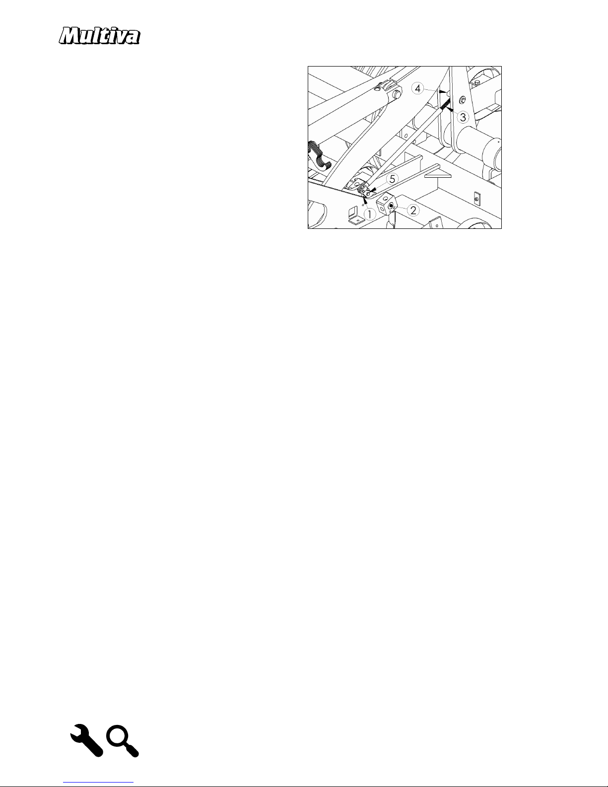
6.4. Bogie bearing clearance
The bogie axles have tapered roller bearings. Checking is made before greasing the bogies. The bearing
clearance is checked by lowering the harrow so that it is supported by the tines and the wheels are off
the ground so that the bogie can move without obstructions. The bogie must move smoothly and there
should not be any play when the bogie is twisted.
The bogie axle clearance is adjusted with the bolt 1 in the bogie plug. The fixing bolt of the locking
plate of the bolt 3 is loosened and the locking plate 2 is removed. After this, the adjustment bolt is
tightened until there is no play. The lock plate is re-installed and if necessary, the adjustment bolt
loosened so that the lock plate can be fitted. The fixing bolt of the lock plate 3 is re-placed and
tightened.
6.5. Hydraulics
Check the tightness of the hydraulic systems and tighten the couplings if necessary.

21
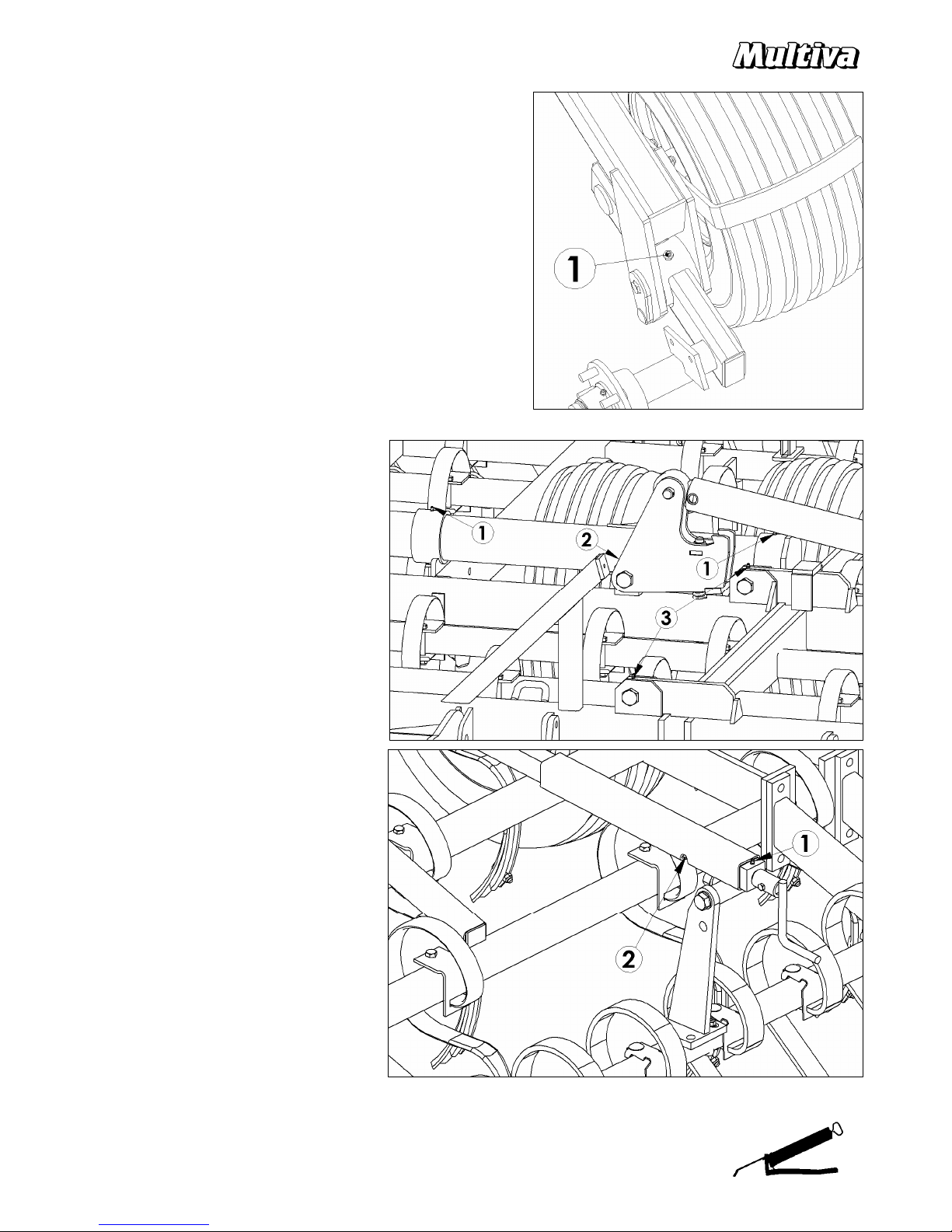
6.6. Side section locking
The operation of the side section locking must be
checked once every operating period before
commissioning the machine.
There is a spring between the plates of the lock
piece that presses the cams behind the plate in the
side section (point 1).
Lock plates should press against the side section
plates so that the cams remain behind the plate
(point 2).
Optima 500-700 :
Side section cylinder opens the locking piece automatically
before the sections start to open. The movement of the lock
piece can be adjusted with screw 3.
Optima 800-1500 :
Small cylinders open the locking pieces first and the the
oil pressure is directed to the side section cylinders.
The movement of the lock piece can be adjusted on the
length of the piston rod 3.
6.7. Front support wheel bearing clearance
Vertical axle of the support wheel has taper roller bearings. Bearing play can be adjusted by opening the
cap and tightening the crown nut. There is a same principle that with the wheel hubs. There should not
be any appreciable slack in the axle.
22
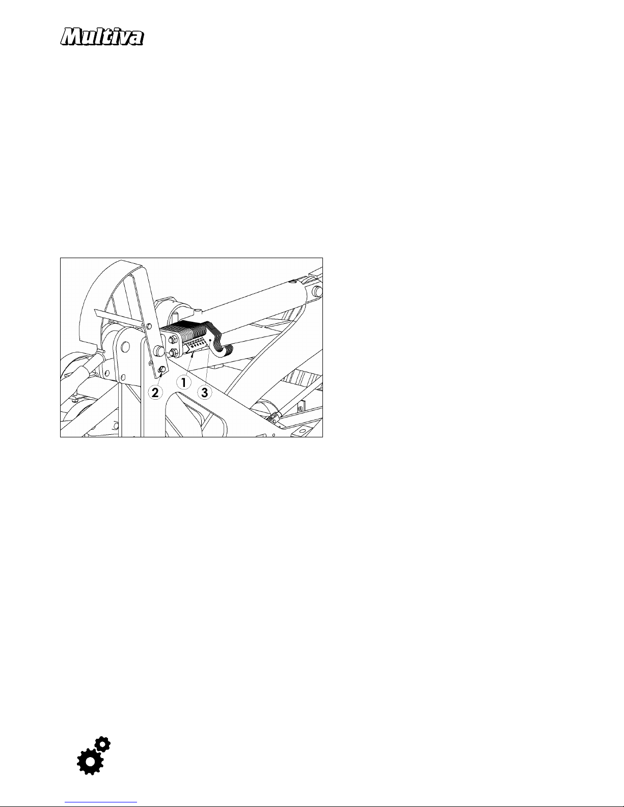
6.8. Selector valve operation
Optima 500 – 700. When the machine is commissioned,
ensure that the selector valve lever is moving without
obstructions.
The movement is checked by lowering the harrow
approximately 50 mm down from the transport position
and moving the actuator arm back and forth.
The locknut at the end of the thread of the actuator arm
must be adjusted so that there is a clearance of a few
millimetres in the actuator arm when the harrow is at
the top transport position.
The spring in the actuator arm of the selector (point 3)
can compress. The valve has a limiter against which the
valve spindle stops in the harrow working position.
The bolt 5 must not be tightened too much. You should be able to rotate the bolt by hand.

23
7. MAINTENANCE PROGRAMME, LUBRICATION
All lubrication points must be re-lubricated after the machine has been washed. DO NOT use a jet
cleaner to directly spray the labels or parts with bearings. Maintain a minimum distance of 30 cm
between the nozzle of the cleaner and the sprayed target.
Clean the lubrication nipples before lubrication. Wipe off excess lubricant. In all points, the lubricant
grease must be applied in the nipple until excess clean grease can be seen coming out of the target.
Some lubrication points only require a few drops -these are specified later on. The lubricant should be
general purpose grease that contains lithium soap and EP additives.
So called pin greases should never be used to lubricate the harrow. Using this type of grease may break
the bearings.
Table columns:
1 ) Daily
2 ) Every 500 ha or once in an operating period
1 )
2 )
500 ha
Cage roller bearings
X
Cage
roller weighing adjustment threads
X
Side section
hinges
X
Wheel hubs
X
Mechanical depth adjustment threads, Optima T500
- T550
X
Towing eye
X
Bogie bearings
X
Middle axle
X
Side section locking
X
Side section
hinges
X
Levelling board adj
ustment threads
X
Hydraulic cylinder
s
pherical bearing
s X
Drawbar piston rod
X
Selector valve spindles, Optima T500
- T700
X
Front support wheel adjustment threads
,
Optima 1000
- 1500
X

24
Cage roller bearings
2 pcs / roller. Point 2.
Cage roller weighing adjustment thread
1 pc / roller. Point 1.
A few drops of grease is applied to the threads
Side section hinges
Point 2.
Wheel hubs
Point 3.
Mechanical depth adjustment threads, Optima
T500
Point 1.
A few drops of lubrication grease is applied to the threads
Towing eye
The towing eye is lubricated by applying lubrication grease to the front and bottom edges.
Rotating towing eye has a grease nipple.
25
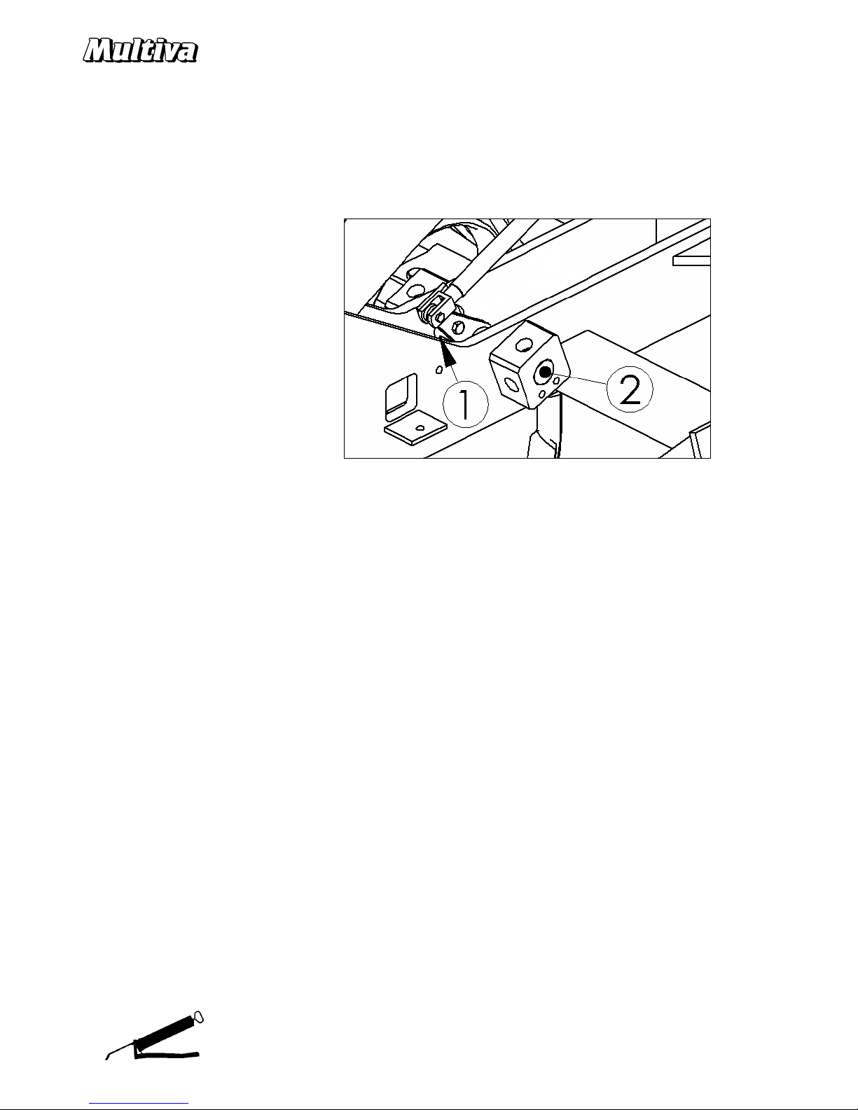
Bogie bearings
Point 1. Ensure that the grease actually goes to the
bearings. Lift the bogies slightly off the ground using
the depth adjustment. Swing the bogie and press
the grease until it comes out through the sealing.
Middle axle bearings
Collars at the centre and the
ends. Point 1.
Side section locking
Point 2.
Side section hinges
Point 3.
Levelling board adjustment
Points 1 and 2.
A few drops of grease is
applied to the lubrication
nipples.
26
Hydraulic cylinder spherical bearings
A few presses of lubrication grease is applied to all lubrication nipples.
Drawbar top link
A few drops of lubrication grease is applied to the lubrication nipples.
Selector valve spindles
2 pcs. Point 2. Spray liquid lubricant on
the axle of the spindle from between the
frame plates (point 1) and from outside
the valve (point 2).
In addition to the most important grease nipples mentioned above, the harrow also has other grease
nipples that are not specified here. They should be lubricated once in an operating period.

27
8. STORAGE
The drawbar of the harrow can be raised up, whereupon the machine uses less storage space.
Raising the drawbar:
1. Lower down the harrow.
2. Disconnect the harrow from the tractor and move the tractor away.
3. Use a proper lifting band and a machine like a front loader to support the drawbar.
4. Remove the upper pin of the top link and remove also the hose bracket from the drawbar.
5. Raise the drawbar up so that you can place a bolt to the hole. Use at least M16 bolt.
The machine must be cleaned and lubricated carefully for long term storage. The hydraulic cylinders
should be set to reveal a minimum amount of the chromed piston rod during storage. The uncovered
piston rod sections must be protected with petrolatum or thick oil.
The tines suffer from supporting the entire weight of the machine for a longer period of storage
(winter). The best way to store the harrow is to elevate it using the centre section corners as support,
whereupon no weight is placed on the tines or tires. The harrow can also be stored by setting all
adjustment pieces in place to the depth adjustment and lowering the harrow on the limiter pieces
during storage.
The tires, bearings and hydraulic hoses can be damaged as a result of long-term outdoor storage.

28
9. WARRANTY
Multiva agricultural machines come with a one-year warranty.
Warranty policy:
1. The manufacturer shall replace, free-of-charge, any parts that become unusable due to defective
workmanship or defective raw materials within the warranty period. However, any parts subject to
wear are not covered by the warranty.
2. Damage caused by misuse, inadequate service, changes unauthorised by the manufacturer, traffic
accidents and other reasons beyond feasible inspection are excluded from the coverage under this
warranty.
3. Damage caused by powering the machine with a clearly over-sized tractor is also excluded.
4. If a failure is repaired by a third party, the manufacturer will only compensate the costs for the
repairs if this procedure has been agreed upon in advance with a representative of the
manufacturer.
5. The manufacturer is not liable for loss of income due to downtime caused by damage or for any
other indirect losses caused by damaged machinery.

29
Appendix 1. EC DECLARATION OF CONFORMITY
DOMETAL OY
Kotimäentie 1
FI-32210 Loimaa
Finland
hereby states that the machine in question
Multiva Optima T500, T600, T700, T800, T900, T1000, T1250, T1500 S-tine harrows
meet the requirements of Machinery Directive 2006/42/EC.
The following standards were applied in the design of the machine:
ISO 4254-1:2013
Loimaa 12.1.2016
Vesa Mäkelä
Kotimäentie 1
FI-32210 Loimaa
Finland
The undersigned is also authorised to compile technical documentation for the above machines.
Translation

30
Appendix 2. Hydraulic schematic Optima T500
Side wings and leveling board Depth control

31
Appendix 3. Hydraulic schematic Optima T600-700
Side wings and leveling board Depth control

32
Appendix 4. Hydraulic schematic Optima T800-900
Depth control Leveling board
Side wings

33
Appendix 5. Hydraulic schematic Optima T1000
Depth control Leveling board
Side wings

34
Appendix 6. Hydraulic schematic Optima T1250
Depth control Leveling board
Side wings

35
Appendix 7. Hydraulic schematic Optima T1500
Leveling board
Depth control
Side wings

36

37
Appendix 8. Connection socket according to SFS 2473
1/L Left turn si
gnal
yellow
2/54G
Free
-
3/31
Ground
white
4/R Right turn signal
green
5/58R
Right rear light
+
reg. plate light
brown
6/54
Brake light
red
7/58L
Left rear light
black
1/L
6/54
2/54G
7/58L
3/31
4/R
5/58R
 Loading...