


MultiSmart
Pump Station Manager & RTU

MultiSmart Installation & Operation Manual
Page 2 of 260 MultiSmart_IO_Manual_R20

MultiSmart Installation & Operation Manual
NOTICE
This Manual is the support documentation for the
installation, commissioning and opera tio n of the
MultiTrode MultiSmart Pump Station Manager/RTU
and Reservoir Monitor.
Revision 20
15 May 2013
This manual is used for v3.1.0 of the MultiSmart Pump Station Manager
This document is proprietary to MultiTrode Pty Ltd (the company) and for sole use within the
company notwithstanding that this doc ument may from time to tim e be made available to the
company’s subcontractors, suppliers, customers and others for purposes associated with
manufacturing and other processes as aut horised on an individual basis by Multi Trode Pty Ltd
or their representative. In such cases where the document has been issued to external
parties, its contents shall not be transcri bed, copied, relayed, or divulged to any other party
whatsoever and after satisfying the requirements f or which the document was originally iss ued
to any external party shall be either returned to the company, or destroyed as required by the
company’s document control procedure and as attested to by the recipient at the time of taking
possession of the document. MultiTrode Pty Ltd shall not be held l i able in any way whats oever
for any act or omission, either direct or consequential, arising from the use of t he information
contained herein.
MULTITRODE is a registered trade mark of MultiTrode Pty Ltd in Australia and many countries worldwide. PUMPVIEW and MULTISMART
are trademarks of MultiTrode Pty Ltd and pending A ustralian trade mark registration. Australian Design Registration is pending for the
MultiSmart Pump Station Manager and RTU Remote and Base Modules. Patent Pending in Australia. © 2012 MultiTrode Pty Ltd. This
publication is protected by copyright. No part of this publication may be reproduced by any process, electronic or otherwise, without the
express written permission of MultiTrode Pty Limited.
MultiSmart_IO_Manual_R20 Page 3 of 260

MultiSmart Installation & Operation Manual
1
Warnings & Cautions ...................................................................................................................... 9
1.1 Information to User ................................................................................................................ 9
1.2 Documentation Standards ...................................................................................................... 9
1.3 Installation Notes ................................................................................................................... 9
2 Glossary & Symbols ..................................................................................................................... 10
3 Major New Features & Enhancements in Recent Firmware Releases ...................................... 11
3.1 Version 3.1.0 ........................................................................................................................ 11
Part 1 – Operations ................................................................................................................................... 12
4 Introduction ................................................................................................................................... 12
4.1 Range of Options ................................................................................................................. 12
4.2 Intuitive Operator Interface ................................................................................................... 13
4.3 Intuitive Engineering Interface .............................................................................................. 13
4.4 "Out of the Box" Control of a Pump Station .......................................................................... 14
5 Operator Interface ......................................................................................................................... 15
5.1 LCD Panel ............................................................................................................................ 15
5.2 LED Indicators ..................................................................................................................... 16
5.3 Buttons ................................................................................................................................. 16
5.4 Using the Interface ............................................................................................................... 16
Part 2 – Installation & Commissioning ................................................................................................... 33
6 Mounting Instructions ................................................................................................................... 33
6.1 Mounting the Operator Interface Display .............................................................................. 33
6.2 Mounting the Pump Station Manager ................................................................................... 35
6.3 Connecting the Operator Interface to the Pump Station Manager ....................................... 35
7 MultiSmart Boards ........................................................................................................................ 36
7.1 Power Supply ....................................................................................................................... 38
7.2 Default Wiring Setup for Pump Control Board ...................................................................... 39
7.3 Pump Control Board ............................................................................................................ 44
7.4 CPU Board ........................................................................................................................... 48
7.5 DSP Board ........................................................................................................................... 49
7.6 Energy Monitoring & Motor Protection Board ....................................................................... 56
8 PumpView Hardware Setup .......................................................................................................... 58
8.1 Fault Finding ........................................................................................................................ 58
8.2 Configuring PumpView for a Serial Cellular Modem ............................................................ 59
8.3 Configuring PumpView for an Ethernet Cellular Router ....................................................... 60
9 Quick Commissioning Guide ....................................................................................................... 63
9.1 Setup Wizard Flow Diagrams ............................................................................................... 64
9.2 Setup Wizard Notes ............................................................................................................. 68
9.3 Unassign Any Faults Not Used ............................................................................................ 70
9.4 Level Simulation Mode ......................................................................................................... 72
9.5 Maintenance Mode .............................................................................................................. 72
Part 3 – Advanced Settings ..................................................................................................................... 74
10 High Level Overview ..................................................................................................................... 74
10.1 MultiSmart Pump Station Manager Overview ...................................................................... 74
10.2 Pump Station Manager ........................................................................................................ 75
10.3 Reservoir Monitor ................................................................................................................. 76
10.4 Pump Control Module .......................................................................................................... 77
10.5 Energy Monitoring and Motor Protection .............................................................................. 78
10.6 Supply Protection ................................................................................................................. 79
10.7 Data Logger ......................................................................................................................... 79
10.8 Flow ..................................................................................................................................... 79
10.9 Fault Module ........................................................................................................................ 79
10.10 Security ................................................................................................................................ 79
10.11 PLC Extension (IEC 61131-3) .............................................................................................. 79
Page 4 of 260 MultiSmart_IO_Manual_R20

MultiSmart Installation & Operation Manual
10.12 Logic Engine ........................................................................................................................ 79
10.13 RTU...................................................................................................................................... 80
11 Security .......................................................................................................................................... 82
11.1 Selecting any Digital Input Tag ............................................................................................ 85
11.2 Security Key Setup .............................................................................................................. 86
11.3 Accessing MultiSmart Without a Security Key ..................................................................... 87
12 Fill / Empty & Pump Setpoints, Alarm Setpoints, Delays .......................................................... 88
12.1 Fill / Empty (Charge / Discharge) ......................................................................................... 88
12.2 Default Pump and Alarm Setpoints ...................................................................................... 88
12.3 Changing Pump and Alarm Levels Setpoints ....................................................................... 89
12.4 Setting Pump & Alarm Delays .............................................................................................. 91
13 Pumps and Groups ....................................................................................................................... 93
13.1 Change Alternation & Fixed Duty ......................................................................................... 94
13.2 Moving Pumps Between Groups, or Changing the Order of Pumps .................................... 96
13.3 Adding or Deleting Groups & Changing Group Alternation .................................................. 96
13.4 Decommissioning Pumps ..................................................................................................... 97
14 Configuring I/O, Fault & Level Devices ....................................................................................... 98
14.1 Digital Inputs ........................................................................................................................ 98
14.2 Assigning Faults to Digital Inputs ......................................................................................... 98
14.3 Unassigning Fault Inputs.................................................................................................... 100
14.4 Configuring Digital Inputs ................................................................................................... 100
14.5 Configuring Analog Inputs .................................................................................................. 103
14.6 Advanced Analog Input Options ......................................................................................... 104
14.7 External Digital & Analog Modules ..................................................................................... 104
14.8 Configuring Level Devices ................................................................................................. 109
14.9 Configuring Faults .............................................................................................................. 122
14.10 Configuring Analog Outputs ............................................................................................... 130
14.11 Configuring Digital Outputs ................................................................................................ 131
15 Profiles ......................................................................................................................................... 135
15.1 Profile Selection Methods .................................................................................................. 136
15.2 Configuring the Setpoints of Profiles .................................................................................. 138
15.3 Configuring Other Profile Properties .................................................................................. 138
16 Station Optimization ................................................................................................................... 140
16.1 Station Optimization Menu ................................................................................................. 141
16.2 Additional Parameters ........................................................................................................ 148
17 Energy Monitoring and Motor Protection .................................................................................. 150
17.1 Setting Motor Protection Values ......................................................................................... 151
17.2 Insulation Resistance Tester .............................................................................................. 154
17.3 Reassigning (Motor) Current Inputs used in Motor Protection ........................................... 158
17.4 Calculating Efficiency ......................................................................................................... 159
18 Supply Protection ........................................................................................................................ 160
18.1 Battery Test ........................................................................................................................ 162
19 Datalogger ................................................................................................................................... 163
19.1 Configuring the Event Logger ............................................................................................ 164
19.2 Crisis Logger ...................................................................................................................... 166
19.3 Interval Logger ................................................................................................................... 168
19.4 Filtering the Data Viewed in the History Page .................................................................... 168
19.5 Storing the Datalogger on the SD Card ............................................................................. 170
19.6 Configuring the datalogger to write directly to an SD Card ................................................ 173
19.7 Adding Comments and Deleting Logs ................................................................................ 173
20 Flow .............................................................................................................................................. 174
20.1 Configure General Flow Setting ......................................................................................... 174
20.2 Configuring Analog Inputs for Flow Measurement ............................................................. 175
20.3 Configuring Analog Inputs for Inflow Measurement ........................................................... 176
MultiSmart_IO_Manual_R20 Page 5 of 260

MultiSmart Installation & Operation Manual
20.4 Configuring Digital Inputs for Flow Measurement .............................................................. 176
20.5 Configuring Calculated Flow Settings ................................................................................ 177
20.6 Flow Alarms ....................................................................................................................... 178
20.7 Smart Outflow .................................................................................................................... 179
20.8 Estimating Duration to Overflow ......................................................................................... 180
21 Reservoir Monitor ........................................................................................................................ 181
21.1 Communications Configuration .......................................................................................... 181
21.2 User Interface .................................................................................................................... 183
21.3 Connection Manager .......................................................................................................... 183
22 RTU Module ................................................................................................................................. 185
22.1 Communications Screen .................................................................................................... 185
22.2 Communication Protocols .................................................................................................. 185
22.3 Enabling and Viewing of DNP and MODBUS Logs ............................................................ 199
22.4 IP Address & Routing Settings ........................................................................................... 200
23 Variable Frequency Drive (VFD) ................................................................................................. 201
23.1 Enabling VFD ..................................................................................................................... 201
23.2 Individual Pump Parameters .............................................................................................. 202
23.3 Setup an Analog Output for use with a VFD Drive ............................................................. 203
23.4 Controlling a VFD Drive Using MODBUS ........................................................................... 203
23.5 Displaying VFD speed on Main Screen.............................................................................. 203
23.6 Calculating Efficiency using VFD ....................................................................................... 203
24 PLC Extension IEC 61131-3 (ISaGRAF) ..................................................................................... 204
24.1 Setting up the Workbench .................................................................................................. 205
24.2 Setting up I/O ..................................................................................................................... 206
24.3 MultiSmart Functions & I/O Blocks ..................................................................................... 206
24.4 Downloading ISaGRAF Resources to MultiS mar t .............................................................. 212
24.5 Compiling and Downloading Multiple Resources ............................................................... 212
24.6 Viewing the Status of ISaGRAF Variables ......................................................................... 212
24.7 The Tags Button ................................................................................................................ 213
24.8 The Params Button ............................................................................................................ 213
24.9 Disabling ISaGRAF Resources .......................................................................................... 213
24.10 Backing Up ISaGRAF Resources ...................................................................................... 213
24.11 ISaGRAF Application Examples ........................................................................................ 214
25 Logic Engine ................................................................................................................................ 215
25.1 MultiSmart Tags ................................................................................................................. 215
25.2 Logic Engine Tags ............................................................................................................. 216
25.3 Mathematical Operators ..................................................................................................... 217
25.4 MultiSmart Logic Functions ................................................................................................ 217
25.5 Advanced Functions .......................................................................................................... 218
25.6 Logic Examples .................................................................................................................. 219
25.7 Uploading Logic Files Using FTP ....................................................................................... 220
25.8 Enabling Logic Files ........................................................................................................... 221
26 SMS Server .................................................................................................................................. 222
27 Customizing the Display ............................................................................................................. 225
27.1 Naming Pumps .................................................................................................................. 225
27.2 Pump Data Display ............................................................................................................ 225
27.3 Bottom Section ................................................................................................................... 226
28 Restarting the MultiSmart ........................................................................................................... 227
29 Site Keys and Enabling New Modules ....................................................................................... 227
29.1 Software Modules Available ............................................................................................... 227
29.2 Enabling Software Modules with a New Site Key ............................................................... 228
30 Upgrading MultiSmart Firmware ................................................................................................ 228
30.1 Upgrading via PC Configuration Utility ............................................................................... 228
31 Backing Up & Restoring Configuration Settings ...................................................................... 229
Page 6 of 260 MultiSmart_IO_Manual_R20

MultiSmart Installation & Operation Manual
31.1 Resetting Defaults .............................................................................................................. 229
31.2 Restore a Backup .............................................................................................................. 230
31.3 Back Up Current Configuration .......................................................................................... 231
32 More Advanced Configuration ................................................................................................... 232
32.1 Default Mode vs. Showing Less Options............................................................................ 232
33 Web Server .................................................................................................................................. 233
33.1 Web Page Security ............................................................................................................ 233
33.2 Security Key Setup ............................................................................................................ 234
34 Troubleshooting .......................................................................................................................... 235
34.1 There is no level displayed on my unit ............................................................................... 235
34.2 Every time the pump starts I see a Contactor Auxiliary fault .............................................. 235
34.3 My unit is showing a “Current Config Fail” fault .................................................................. 236
34.4 My unit has started with the message “Fail Safe Mode”..................................................... 236
34.5 PPP2 Manager Connection Error ....................................................................................... 236
34.6 My unit keeps restarting ..................................................................................................... 236
35 Appendix A – Fault Message Glossary ..................................................................................... 237
36 Appendix B – Display Mounting Template – Metric Units ....................................................... 241
37 Appendix C – Display Mounting Template – US / Imperial Units ............................................ 242
38 Appendix D – MultiSmart Security Explained ........................................................................... 243
39 Appendix D – MultiSmart Web Security Explained .................................................................. 245
40 Appendix E – Setting Up WITS-DNP Communications ............................................................ 247
40.1 Basic Configuration ............................................................................................................ 247
40.2 Connection Details ............................................................................................................. 248
40.3 Handling of Redundant Channels with Connection Details ................................................ 249
40.4 Device On/Off Scan ........................................................................................................... 249
40.5 Scheduled Connection ....................................................................................................... 249
40.6 Point On/Off Scan .............................................................................................................. 250
40.7 Analogue Range/Scaling.................................................................................................... 250
40.8 Analogue Limits ................................................................................................................. 250
40.9 Counter Limits .................................................................................................................... 251
40.10 Point Archives .................................................................................................................... 251
40.11 Binary States ...................................................................................................................... 251
40.12 Profiles ............................................................................................................................... 251
40.13 Rate of Change .................................................................................................................. 251
40.14 Object Flag Actions ............................................................................................................ 252
40.15 Minimum, Maximum, and Mean ......................................................................................... 252
40.16 Integral Values ................................................................................................................... 252
40.17 State Counter ..................................................................................................................... 253
40.18 State Runtime .................................................................................................................... 253
40.19 Profile Control Value .......................................................................................................... 253
40.20 Bulk Configurations and Versions ...................................................................................... 254
40.21 Event Logs ......................................................................................................................... 255
41 Technical Specifications ............................................................................................................ 256
41.1 Processor Unit ................................................................................................................... 256
41.2 RTU/Communications ........................................................................................................ 256
41.3 Firmware/Application Upgrade Capability .......................................................................... 256
41.4 I/O Standard Modules ........................................................................................................ 256
41.5 I/O-3MP: Motor Protection I/O Board ................................................................................. 256
41.6 Power (per unit) ................................................................................................................. 256
41.7 Power Supply & Environmental .......................................................................................... 256
41.8 Product Dimensions ........................................................................................................... 256
42 MultiTrode Terms & Conditions of Sale .................................................................................... 257
MultiSmart_IO_Manual_R20 Page 7 of 260

MultiSmart Installation & Operation Manual
Summary of Tables
Table 1 – Power Supply Specifications ......................................................................................................................................... 38
Table 2 – Serial Port Pin Outs ...................................................................................................................................................... 49
Table 3 – Max. Cable Length at Specific Baud Rates ................................................................................................................... 52
Table 4 – Can BUS and Can ID Settings ...................................................................................................................................... 53
Table 5 – Key Setup Parameters (can only be modified through the Setup Wizard) .................................................................... 68
Table 6 – Alternation Schemes ..................................................................................................................................................... 93
Table 7 – Digital Input Fault Sources ............................................................................................................................................ 98
Table 8 – Advanced Digital Input Options ................................................................................................................................... 101
Table 9 – Digital Input Mode Examples ...................................................................................................................................... 102
Table 10 – Digital Input Capa b ilities ........................................................................................................................................... 102
Table 11 – Advanced Analog Input Options................................................................................................................................ 104
Table 12 – Advanced Probe Settings ......................................................................................................................................... 112
Table 13 – Probe Length in Inches ............................................................................................................................................. 115
Table 14 – DuoProbe Calibration Parameters ............................................................................................................................ 116
Table 15 – Advanced Fault Parameters ..................................................................................................................................... 123
Table 16 – Fault Actions Parameters .......................................................................................................................................... 125
Table 17 – Digital Output Sources .............................................................................................................................................. 132
Table 18 – Advanced Digital Output Options .............................................................................................................................. 133
Table 19 – Station Optimization Parameters .............................................................................................................................. 140
Table 20 – Pump Reversal Parameters ...................................................................................................................................... 143
Table 21 – Well Washer Parameter s .......................................................................................................................................... 146
Table 22 – CT & FLC Parameters .............................................................................................................................................. 152
Table 23 – Motor Protection Faults ............................................................................................................................................. 152
Table 24 – Basic Fault Options ................................................................................................................................................... 153
Table 25 – IRT Parameters......................................................................................................................................................... 154
Table 24 – Basic IRT Parameters ............................................................................................................................................... 156
Table 26 – Supply Protection Faults ........................................................................................................................................... 161
Table 27 – Supply Protection Fault Parameters ......................................................................................................................... 161
Table 28 – Battery Test Parameters ........................................................................................................................................... 162
Table 29 – Event Datalogger Param eter s ................................................................................................................................... 165
Table 30 – Crisis Logger Configuration for “Trigger” Parameters ............................................................................................... 167
Table 31 – Interval Logger Configuration Parameters ................................................................................................................ 168
Table 32 – Predefined Filters Available in General Filters .......................................................................................................... 169
Table 33 – Filenames for Each Type of Datalog file ................................................................................................................... 171
Table 34 – General Flow Fault Parameters ................................................................................................................................ 174
Table 35 – Smart Outflow Parameters ........................................................................................................................................ 179
Table 36 – Advanced Serial Port Parameters ............................................................................................................................. 195
Table 37 – VFD Parameters ....................................................................................................................................................... 202
Table 38 – ISaGRAF Device Names .......................................................................................................................................... 206
Table 39 – Example of MultiSmart Tags ..................................................................................................................................... 216
Table 40 – Logic Engine Mathematic Operators ......................................................................................................................... 217
Table 41 – Logic Engine Functions ............................................................................................................................................. 217
Table 42 – Logic Engine Advanced Functions ............................................................................................................................ 218
Table 43 - Customize Display - Pump Data ................................................................................................................................ 226
Table 44 - Customize Display - Bottom 3 Lines .......................................................................................................................... 226
Page 8 of 260 MultiSmart_IO_Manual_R20

MultiSmart Installation & Operation Manual
1 Warnings & Cautions
1.1 Information to User
Read through this m anual to obtain a good working kno wledge in order to get max imum perform ance from
the MultiSmart for your application. After reading, place the manual in a safe place for future reference.
1.2 Documentation Sta ndards
DANGER:
THIS SYMBOL IS USED WHERE NON-COMPLIANCE COULD RESUL T IN INJURY OR DEATH.
WARNING:
THIS SYMBOL IS USED WHERE NON-COMPLIANCE COULD RESULT IN INCORRECT
OPERATION, DAMAGE TO OR FAILURE OF THE EQUIPMENT.
NOTE:
THIS SYMBOL IS USED TO HIGHLIGHT AN ISSUE OR SPECIAL CASE WITHIN THE BODY OF
THE MANUAL.
1.3 Installa ti on Note s
WARNING:
THE MULTIS MART INSTALLATION AND WIRING MUST BE PERFORMED BY QUALIFIED
PERSONNEL.
DANGER:
THE MULTISMART HAS NO USER SERVICEABLE PARTS. TO REDUCE THE RISK OF
ELECTRIC SHOCK, LEAVE ALL SERVICING TO QUALIFIED MULTITRODE TECHNICAL STAFF.
DANGER:
INSTALLATION OR USE OF THIS EQUIPMENT OTHER THAN IN ACCORDANCE WITH THE
MANUFACTURERS INSTRUCTIONS MAY RESULT IN EXPOSURE TO HARM, SERIOUS I NJURY
OR DEATH.
MultiSmart_IO_Manual_R20 Page 9 of 260

MultiSmart Installation & Operation Manual
Abbreviations, Symbols & Units
2 Glossary & Symbols
Terminology
Activation Level
Alternate Mode
Deactivation Level
Decommissioned Pump
Duty (Lead) Pump
Empty (Discharge) Mode
Fill (Charge) Mode
Fixed Sequence
InterPump Start Delay
InterPump Stop Delay
Probe
Standby (Lag) Pump
The point at which a pump or alarm is switched On.
The Pump Station Manager automatically switches the lead (duty) pump each cycle.
The point at which a pump or alarm is switched Off.
A pump that has been removed from duty or an installation, e.g. for maintenance
purposes.
The main pump or the first pump to start within a pumping cycle.
When the Pump Station Manager is set to empty a tank or pit.
When the Pump Station Manager is set to fill a tank or pit.
Pump 1 or pump 2 is fixed as the lead (duty) pump.
The delay between any two pumps starting.
The delay between any two pumps stopping.
MultiTrode manufactures a range of conductive level sensors. They have many
advantages over traditional devices such as ball floats. Advantages include:
resistance to fatty deposit build-up, tangle-free and an adjustable sensitivity to liquid
to prevent false readings.
The secondary pump or the next pump to start within a pumping cycle.
ISaGRAF
PSM
Ω
EMC
Hz
LED
MTU
N/C
N/O
RTU
VAC
VDC
ISaGRAF is a control software environment which supports all of the internationally
recognised IEC 61131-3 control languages and offers a combination of highly
portable and robust control engine.
Pump Station Manager
Resistance Value (Ohm)
Electromagnetic Compatibility
Frequency (Hertz)
Light Emitting Diode
Master Terminal Unit
Normally Closed
Normally Open
Remote Telemetry Unit
Alternating Current Voltage
Direct Current Voltage
VFD
Page 10 of 260 MultiSmart_IO_Manual_R20
Variable Frequency Drive

MultiSmart Installation & Operation Manual
3 Major New Features & Enhancements in Recent Firmware Releases
3.1 Version 3.1.0
Version 3.1.0 includes a large number of enhancements and bug fixes. This section lists some of the major
highlights of this release.
3.1.1 New Features
• Enhanced security features supporting different levels of security for accessing screens
• SMS Server functionality for sending SMS messages on alarm conditions
• Web-based monitoring services and web security for accessing web pages
• Well cleanout can now be controlled by watching current drawn
• Ability to calculate statistics whenever event triggers occur (e.g. average, minimum, and maximum
current while the pump is running)
• Support for DNP Secure Authentication Version 5
• Support for WITS-DNP V2.0
3.1.2 Screen Changes
• Setup Wizard redesign – once completed, users are prompted to set up additional common features
• Device network information now displayed on a Network page under the Info group of pages
• Deactivating faults now show time until reset
• Faults in the fault screen are now shown in order of most recent fault first
MultiSmart_IO_Manual_R20 Page 11 of 260

MultiSmart Installation & Operation Manual
Part 1 – Operations
4 Introduction
Congratulations on your purchase of the MultiTrode MultiSmart Pump Station Manager.
Depending on the options you have purchased, the unit may be configured as either a Pump Station
Manager or a Reservoir Monitor or as a Remote Telemetry Unit. The generic product description of
MultiSmart Pump Station Manager is used throu ghout the manual and for conveni ence refers to any of the
three configurations.
The pump station manager is an "out of the box" Pump Station Manager for water and sewerage pump
stations. The large LCD s creen with sof t-ke ys eliminates the n eed for selec tor switches, p ush buttons , fault
lights, meters, accumulators and other additional panel items. This simplifies panel wiring and reduces
costs.
The product has a very low “whole of life” cost compared with a PLC due to the pum p control functionality
already developed in the product. Users simply configure the parameters, rather than program the unit. This
reduces engineering cost and greatly increases reliability.
The MultiSmart pump station manager has t h e op tio n o f an IEC 6 113 1-3 PLC program m ing lan gua ge so that
additional functionality can be added by the user if required.
The MultiSm art has fully open communications and c an be supplied with Modbus and DNP3 protocols. A
MultiSmart can also be shipped just as an RTU without any pump control functionality or user interface.
The Reservoir Mon itor is a version of the product for monitoring reservoi rs and communic ating with remote
pump stations.
MultiSmart is fully config urable f rom the LCD us er inter face. H owever, ther e is al so a PC -based Configurator
program with comprehensive functionali t y now availa b le.
4.1 Range of Options
The functionality of the basic product can be enhanced with additional software modules, such as:
• DNP3 RTU with security
• Security key - based on the ‘Dallas Key’
• VFD control - variable frequency/speed drive
• “Energy Monitoring and Motor protection” option which allows power, energy, power factor and
pump efficiency monitoring as well as 3-phase currents, motor protection functions and insulation
resistance tests (requires energy monitoring and motor protection I/O module)
• Logic engine (for custom logic additions)
• ISaGRAF (IEC 61131-3) PLC programming
• Well Mixer
• PumpView – a web-based monitoring and control system via the cellular/mobile network
• SMS Server - for sending SMS messages in the event of configured alarm conditions
The product can be shipped with these software modules enabled or they can be enable d in the field with the
appropriate enable code. T o the base uni t, an add itio nal I/O boar d can b e instal led in t he fac tory to all ow for
either an expansion of I/O or motor protection options.
Page 12 of 260 MultiSmart_IO_Manual_R20

MultiSmart Installation & Operation Manual
4.2 Intuitive Operator Interface
The MultiSmart has screens which have been designed for operators of pump stations. The operator can see
at a glance:
• Level
• Pump mode
• Pump availability
• Detailed fault information
• Date/time of each fault occurring and clearing
• Single or 3-phase supply, DC supply
• Fault and event history (up to 50,000 records, or millions of records with SD card)
• Accumulators (starts, hours, faults, etc)
• Pump efficiency (requires energy monitoring, motor protection and flow enabled)
• Status of all I/O
• Status of a communications link
• Duration to Overflow
4.3 Intuitive Engineering Interface
The product has clear menu screens for altering:
• Pump set points
• Alarm set points
• Delays
• Alternation and grouping
• Level device and backup level device
• Number of pumps
• I/O and fault configuration
• Supply protection
• Energy Monitoring and Motor protection (where installed)
• Station optimization parameters (max run time, max off time, max starts per hour, plus many more)
• Data logging parameters
• Communications
• Profiles
MultiSmart_IO_Manual_R20 Page 13 of 260

MultiSmart Installation & Operation Manual
gases or powders.
4.4 "Out of the Box" Control of a Pump Station
When the unit is first power ed up, it starts controlling a pum p station using its def ault parameters. Although
it’s shipped with this basic configurat ion, the configur ation can be easily modified to suit a wide range of
applications by running through the Setup Wizard.
The Setup W izard takes into ac count the MultiTrode probe or other level devices, fill or em pty applications,
number of pumps, num ber of wells, station power supply, type of pum p sensors and DNP comm unication
settings.
Even though the basic setup meets most of the normal pump station requirements, with a few button presses
the MultiSmart can be setup to perform most of the complex pump station management requirements.
Changing between a reser voir and a pump station, the number of pum ps, the number of wells, or empty
(discharge) to fill ( charge) is done through t he Setup W izard an d takes onl y a few m inutes, whi ch is far less
time than that required to implement the same functionality using a standard PLC.
Complete station setups can be saved and/or loaded via an SD card or USB.
If the extensive rang e of existing features do not cover a part icular requirement, additional functionality can
be added by writing new code using either Logic Engine (a simple Boolean language) or ISaGRAF (a suite of
PLC languages).
WARNING:
Do not use this unit in environments that may contain flammable/explosive or chemically aggressive
Page 14 of 260 MultiSmart_IO_Manual_R20
MultiSmart Installation & Operation Manual
5 Operator Interface
The MultiSmart pum p station m anager has an easy to use in terface f eaturing a large graphica l LCD. A large
amount of critical information is displa yed on the main screen, m aking it simple for an operator to determ ine
the current status of the pump station at a glance.
The buttons (or soft-keys) aroun d the edge of the screen ar e used t o access f eatures, depending on what is
displayed at the time.
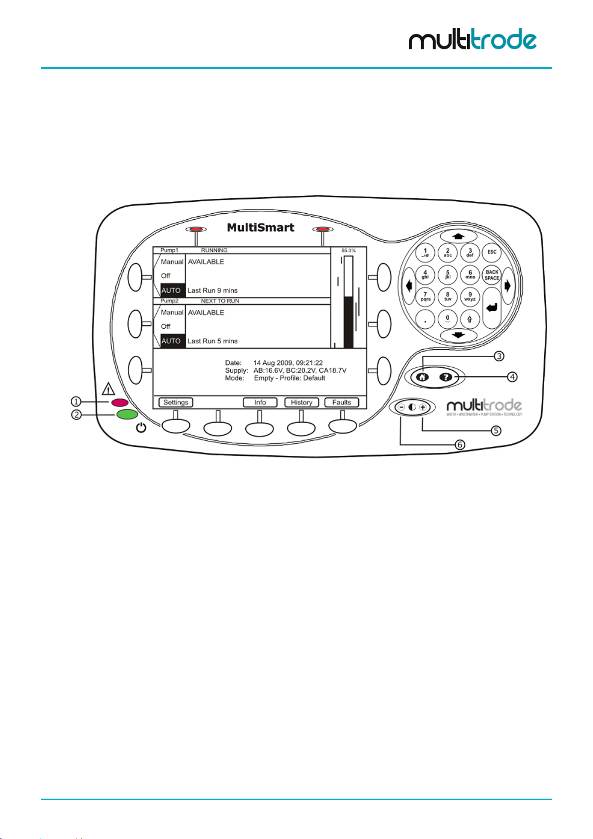
Figure 1 – MultiSmart Display
1. Fault Indication LED (Red)
2. Power Status LED (Green)
3. Home Button
4. Help Button
5. Increase Contrast
6. Decrease Contrast
5.1 LCD Panel
The large LCD gives the oper ator a clear view of how the pum p station is opera ting. Water levels are shown
graphically. A back light turns on when any of the display butto ns are pushed. The back light turns off again
after a set time of inactivity (this time is user configurable).
MultiSmart_IO_Manual_R20 Page 15 of 260
MultiSmart Installation & Operation Manual
5.2 LED Indicators
5.2.1 Power
The Power LED is at the bottom left hand corner of the display and indicates that the DC supply is connected
and turned on.
5.2.2 Faults
The fault LED is above the power LED. It flashes on ce a second when a fault is detec ted. This gives the
operator a quick indication of whether a fault is present without having to access the LCD screen.
5.3 Buttons
5.3.1 Home/Help Button
The Home/Help button has two positions:
• Press ing the Home icon returns the user to the main status screen.
• Pressing the Help icon displays online help for the currently displayed screen.
5.3.2 Contrast Button
The contrast button is us ed to adjust the LCD scr een’s contr ast. Press “ +” or “–“ as required to optimis e the
display for the light conditions.
5.3.3 Display Buttons
Eleven buttons are loc ated ar ound the ed ge of the LC D displa y. These ar e used to ac cess m enu item s and
other data on the display. For any screen, the display indicates what each button is used for.
5.3.4 Numerical Keypad
A numerical keypad is locat ed at the right of the interface. This is us ed to enter alpha-numeric character s
during configuration.
5.4 Using the Interfa ce
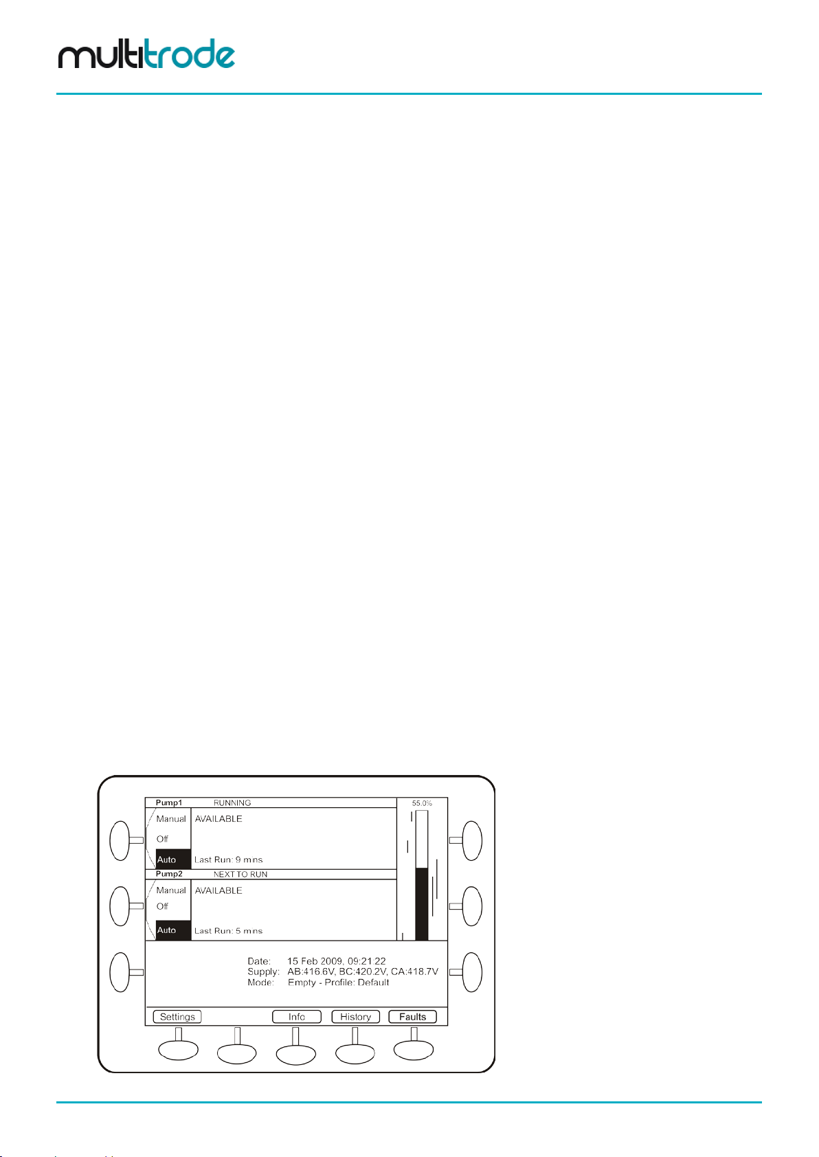
5.4.1 Main Status Screen
Pressing the Home butt on turns on the LCD backlight and als o returns the MultiSmart displa y to the main
status screen. The following screen displays the current status of all pumps connected to the MultiSmart:
Figure 2 – Main Status Screen
Page 16 of 260 MultiSmart_IO_Manual_R20

MultiSmart Installation & Operation Manual
5.4.1.1 Pump Mode The buttons located next to each pump are used to switch the pump into Manual (Hand), Off, or Auto modes.
• Auto – I n this mode a pum p starts when the activation s etpoint is reache d. The pum p automaticall y
stops when the deactivation setpoint is reached.
• Off – This turns a pump off, so pump run commands are ignored b y the of f pump regardless of leve l.
In order to meet secur ity requirements, the Of f mode can be disabled from the advanced menu. (If
changed while the pump is already in the Off mode, it stays off until the mode changes).
• Manual (Hand) – is semi-automatic manual, as the mode returns automatically to Auto when the
deactivation setpoint of the pump is reached. (This prevents pumps from being left on
unintentionally).
A pump is placed into Full Manual m ode as follows: when the pump is in Off mode, instead of just
briefly pressing the Auto/Off/Manual button, press and hold it on. This puts the pump into Full
Manual mode for as long as the button is pressed.
5.4.1.2 Running Status The Running Status of each pump appears to the right of the Pump Name. The various states are:
• Stopped – Pump is stopped
• Starting in x seconds – Pump is about to start and a delay is counting down
• Running – Pump is running
• Stopping in x seconds – Pump is about to stop and a delay is counting down
• Next to Run – Indicates the next pump to run. (Not applicable in multiple well configurations).
• Request to Run – The controller is waiting for the feedback from the contactor. (A contactor
auxiliary is wired in and the command to run a pump has been sent).
• External Run - If the pump is started by an external control method (for example, via a manual
override switch), the contactor will be closed but no run command would have been sent by the
controller, hence External Run is displa yed. The Mu ltiSmart c ontinues to up date the pum p run time
statistics and other relevant historical data. As well, the relevant faults and warnings are generated.
• Reversing in x seconds – The pump is about to reverse
• Reversing for x seconds – The pump is currently being reversed
• Decommissioned – The pump has been taken out of service
5.4.1.3 Availability Status The Availability of each pump is displayed below the Running Status. The states are:
• Available – There are no curr ent faults for this pump. The pum p is available to run ( this condition
does not consider the mode of the pump, so if the pump is OFF, the pump will not run).
• Unavailable – A fault is present or a fault requires manual acknowledgment.
• Hold Out – The text,” Hold Out” flashes indicating a fault is present and the pump is unavailable.
• Inhibit – Station or individual pump inhibited from SCADA
5.4.1.4 Fault Status The Fault Status of each pump is displayed below the Availability Status. The states are:
• Fault Present
• Ack Required – A fault condition has cleared and is not holding out the pump, but requires
acknowledgement.
• Reset Required – A fault condition has cl eared and is holding out the pum p, so requires reset (see
Section 5.4.2).
• Reset in x sec – A f ault condition has clear ed and the pum p will auto-reset when the count down is
complete.
MultiSmart_IO_Manual_R20 Page 17 of 260
MultiSmart Installation & Operation Manual
A bar graph is displayed next to the pumps and shows:
55.0%
Lag (Standby) Pump
activation and deactivation levels
Lead (Duty) Pump
activation and deactivation levels
Level Alarms
Figure 3 – Level Indication
than 1 well.
5.4.1.5 Level Indication and Setpoints Display
• Current liquid level
• Each pump’s activation and deactivation levels
• Level alarms that have been enabled
5.4.1.6 Soft-keys The buttons at the bottom of the screen are used to access the following areas:
• Settings - used to configure the MultiSmart pump station manager
• Info: displays full station and pump information
• History: shows alarms and event history
• Faults: shows details of current fault conditions
NOTE:
When the unit is controlling 5 or more pumps, a Next Pumps button also appears on the bottom line
allowing access to pumps 5 and 6, etc. This button is also present when the unit is configured for more
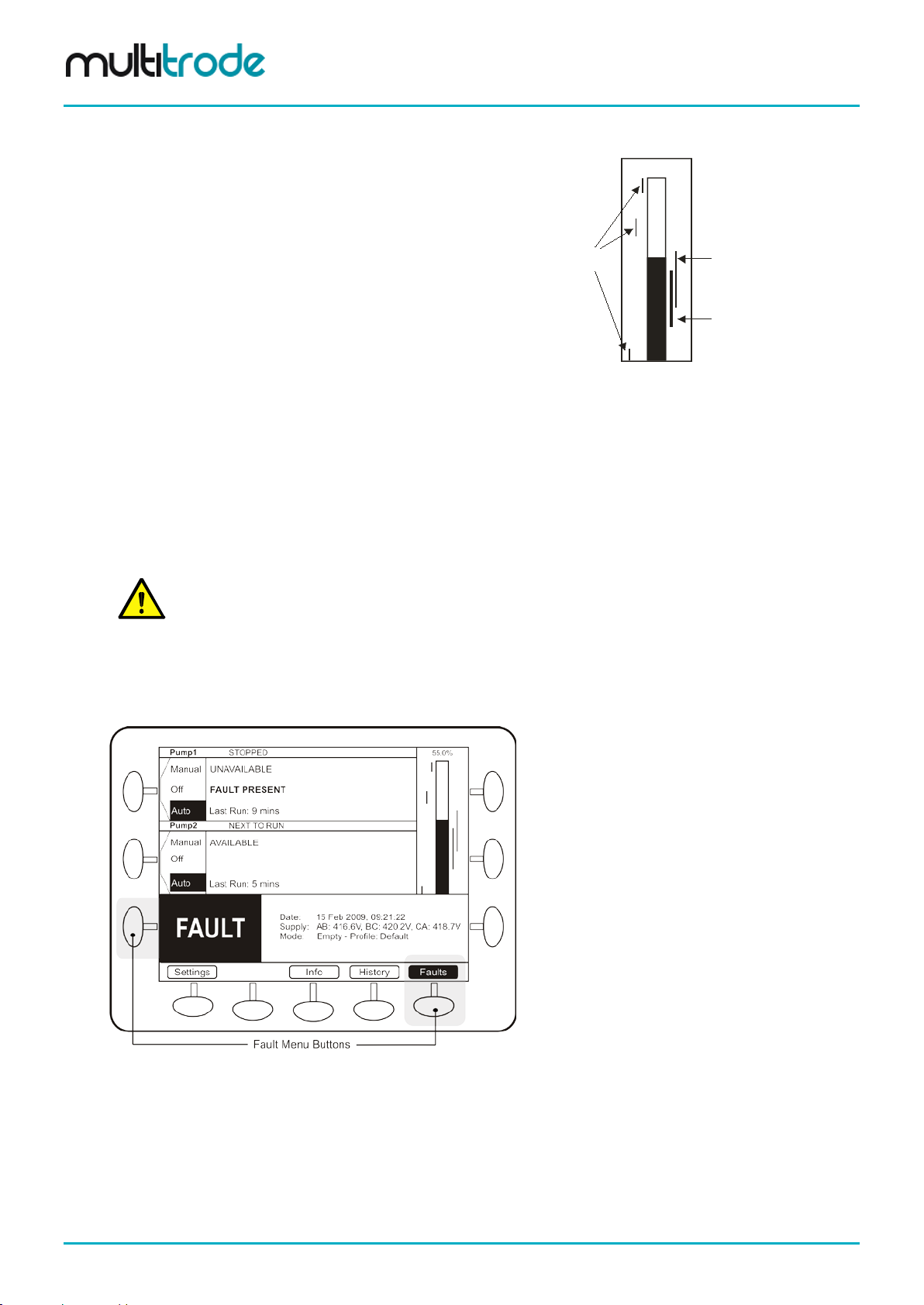
5.4.2 Faults / History
When a fault occurs, a large FAULT box is displayed at the bottom of the screen. At the s ame time, the fault
status changes to Fault Present.
Figure 4 – Fault Indication
The left Fault soft-key butt on flashes when a fault is p res ent. Pus hing t his button (or the rig ht Faul ts bu tton)
displays a screen which det ails the fault. (Appendix A contains a description of all faults displayed).
Page 18 of 260 MultiSmart_IO_Manual_R20
MultiSmart Installation & Operation Manual
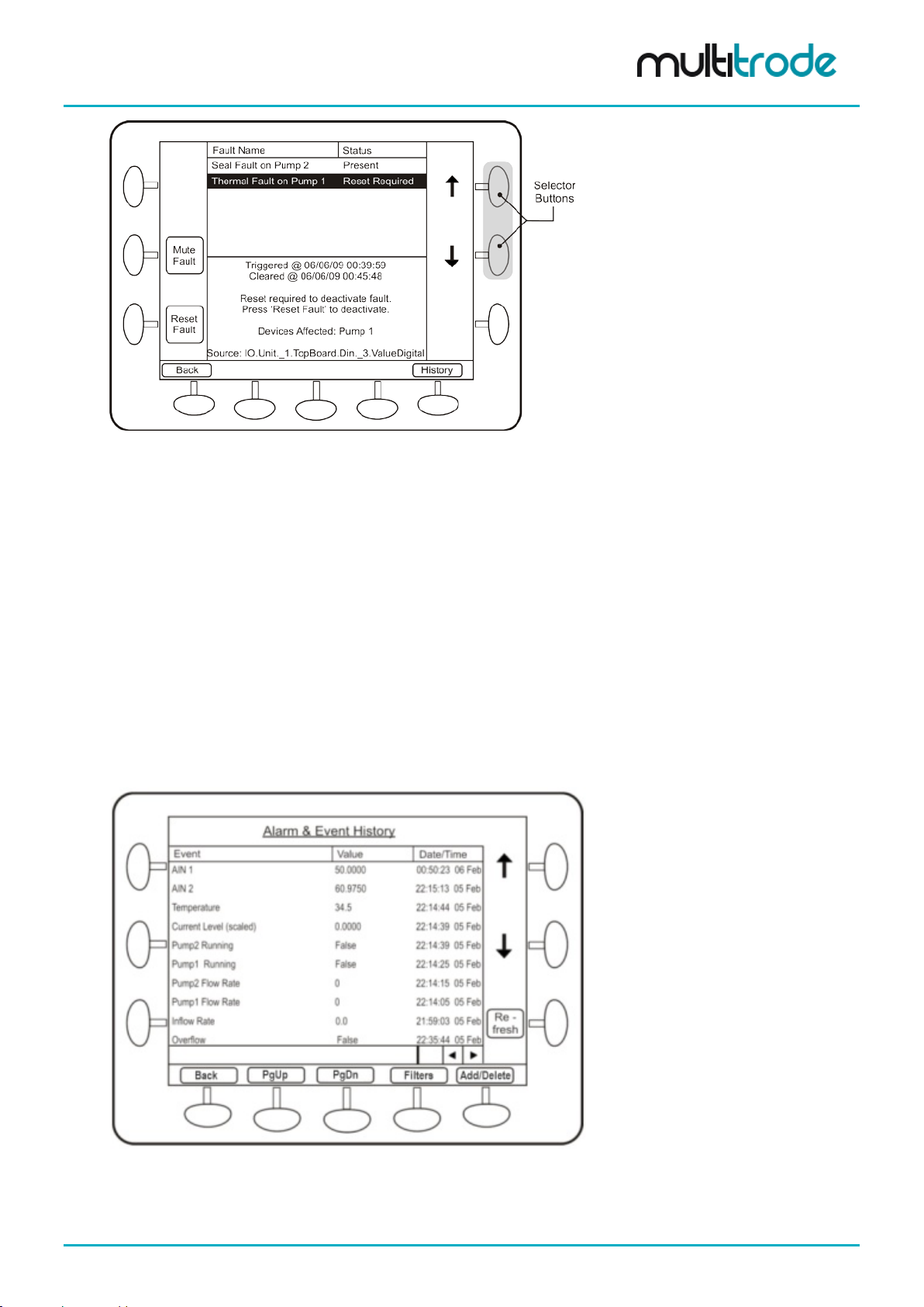
Figure 5 – Fault Reset Screen
Use the selector buttons to select each fault in turn.
From this screen the opera tor can reset the fault if the f ault condition is no long er present. If the fault is still
present, the Reset Fault button does not appear.
A Mute Fault button appears for faults that can be muted. It is used to s top sirens or flashing li ghts t hat may
have been activated by the fault.
A Reboot Unit button app ears for a Config Changed - Reboot Required fault. Pres sing this butt on will save
current values and then reboot the unit. Press the Yes button to confirm a restart of the controller. This
process takes one to two minutes to complete.
By default, digital out put 4 (DO4) is linked to th e high-le vel alarm and can be m uted. The digital out put can
be configured for Pulsed or Steady operation and is typically connected to an external warning light or alarm.
• The Mute button is only available for other faults if the user has configured them to be mutable.
• Press ing the History button displays the entire fault & event history log.
• Press ing the Main button returns the operator to the main status screen.
Figure 6 – Fault History S creen
Section 19.4 explains more about Filters and section 19.7 explains the Add/Delete button.
MultiSmart_IO_Manual_R20 Page 19 of 260
MultiSmart Installation & Operation Manual
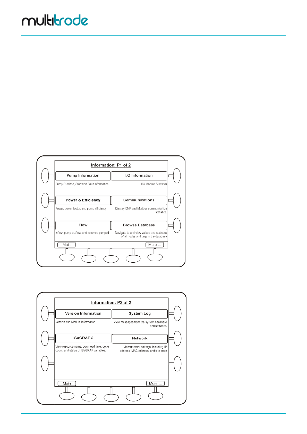
5.4.3 Information Screen
The Information screens show:
• Hours run, starts and faults for each pump and the station
• The status of all I/O
• Flow data (when the optional flow module is installed)
• System log (identifies any application problems)
• Version and modules installed in the unit
• Power and Efficiency – kW, kVA, power factor, pump efficiency, energy accumulators (kWh and
kVAh) for various periods: toda y/ yesterd a y; this week /las t week
• Communications statistics for DNP3/ Modbus slave and the current DNP3 Modbus tag values
• Option to browse MultiSmart internal tag database
• Option to view ISaGRAF 5 tags and values useful for PLC programming
To navigate to the Information screen, press the Info button on the main operator screen.
Figure 7 – Information Screen 1 of 2
Pressing More displays the second scr een, which includes the Version button which gives details on the
firmware version installed on the unit. (Free firmware upgrades are available from the MultiTrode website).
Figure 8 – Information Screen 2 of 2
Page 20 of 260 MultiSmart_IO_Manual_R20
MultiSmart Installation & Operation Manual
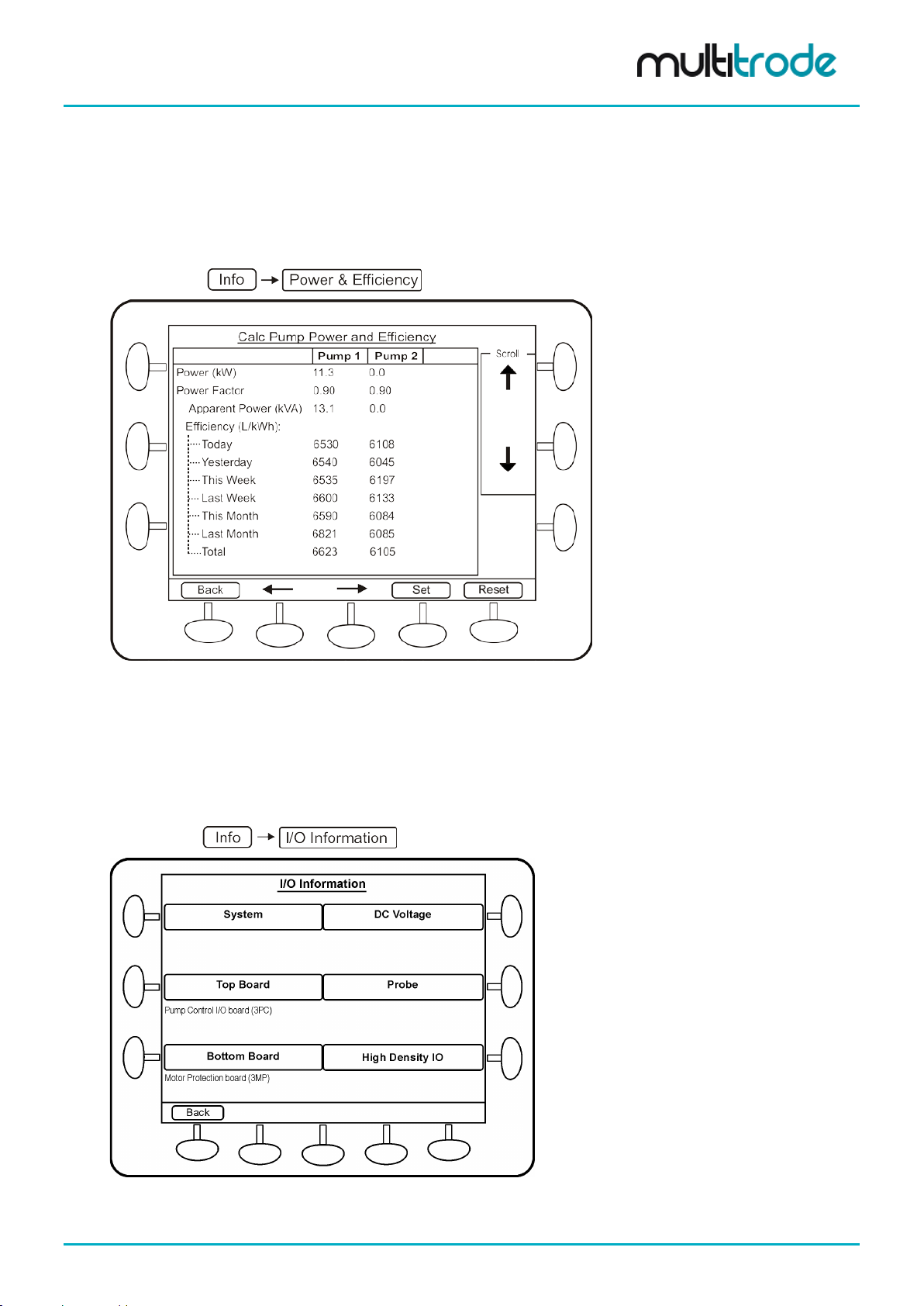
5.4.3.1 Power & Efficiency This screen shows the power fac tor and ef ficienc y of the pumps . Efficienc y, energ y and appare nt ener gy of
the present day, yesterday, this week, last week, this month, last month and totals are displayed on this
screen. There is also a Benchmark Efficiency (further down the screen) which can be entered as a
comparison value (see section 17.1).
Navigate to:
Figure 9 – Power Efficiency Screen
5.4.3.2 I/O Information Information about the S ystem, DC Voltage, Top Board, Bott om Boar d and Probe c an be seen in this s creen.
The I/O information sc reens are especiall y useful in troubles hooting input/output related issues. Insulation
Resistance test (IRT) can be accessed from within the I/O information sc reen, (the test is only performed
when the pumps are not running).
Navigate to:
Figure 10 – I/O Information Screen
MultiSmart_IO_Manual_R20 Page 21 of 260
MultiSmart Installation & Operation Manual
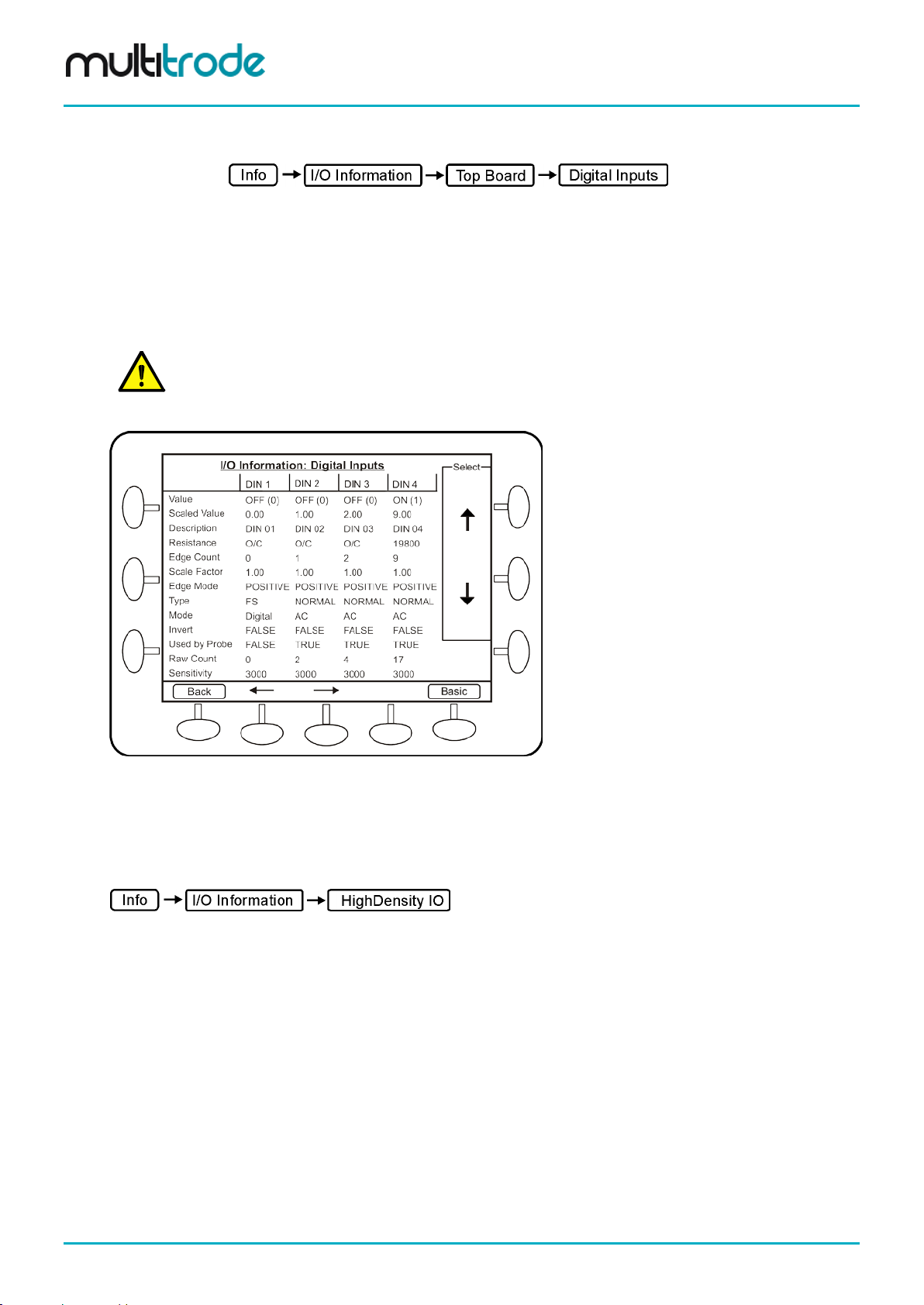
in the digital inputs advanced options.
To determine the configuration and current state of the digital inputs, navigate to the I/O Information: Digital
Inputs screen.
The current state of a digital input is displayed on the top line: Value.
Press the Advanced button to displa y configuration inform ation on the digita l inputs, f or example Mo de and
Sensitivity.
The resistance as measured by the input is also displayed in Advanced mode. When the measured
resistance is below the Sensitivity, then the inp ut turns on (unless it is in verted, in which cas e the reverse i s
true).
NOTE:
The Sensitivity used by the probe (default of 22k ohms, Section 14.8.3
) is not the same Sensitivity found
Figure 11 – Digital Inputs Information Screen
High Density IO info page screens display the state of all digital inputs/outputs on one page for one
unit/board at a time. T he unit name and board name are displa yed at the top. By pressing the N ext/Prev
button, the I/O for the next/previous unit/board can be viewed.
To determine the current state of all digital input s/outputs, navigate to the I/O Information: High Density IO
Page 22 of 260 MultiSmart_IO_Manual_R20
MultiSmart Installation & Operation Manual
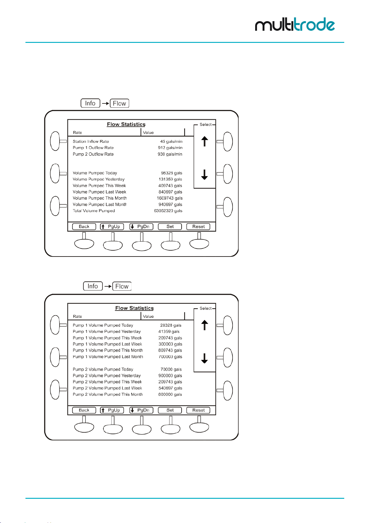
5.4.3.3 Flow The station inflow rate, pum p outflow rat e, volum e pumped dur ing a range of inter vals, number of overflows ,
last overflow tim e, last overf low duration, duratio n to overf low, and total o verflow volume can be se en in th is
screen.
Navigate to:
Figure 12 – Flow Screen – Part 1
Navigate to: and scroll down.
Figure 13 – Flow Screen - Part 2
MultiSmart_IO_Manual_R20 Page 23 of 260
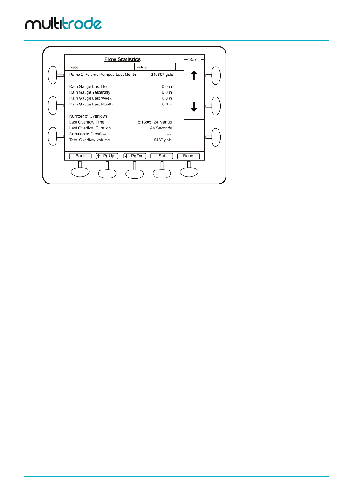
Figure 14 – Flow Screen - Part 3
MultiSmart Installation & Operation Manual
Page 24 of 260 MultiSmart_IO_Manual_R20
MultiSmart Installation & Operation Manual
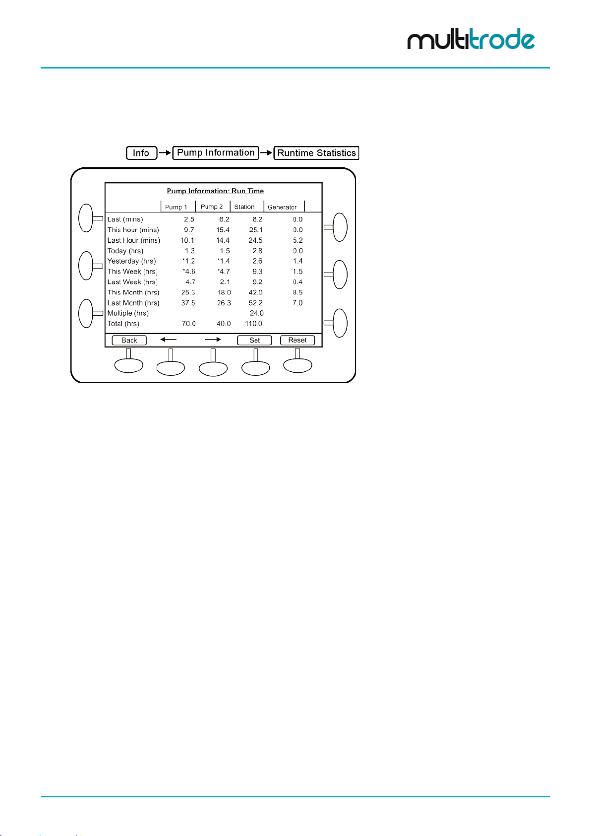
5.4.3.4 Pump Information Under this screen, the Runtime, Start, Reverse and Fault statistics as well as IRT information can be
accessed. These options are illustrated in this section.
(a) Runtime Statistics
Navigate to:
Figure 15 – Pump Run Time Statistics
Runtime is calculated base d on when the pum p is considered run ning via the con tactor auxil iary status. T his
includes when the pump is externally run (determined via the contactor auxiliary status). If no contactor
auxiliary is wire d in, the runtime is c alculated from when t he pump is called for by MultiSmart, and ext ernal
pump runs (e.g. via external switch) will not be included. This is also the case for Starts (below).
In the case of the runtime statistic s, t he station runtime may not equal th e sum of the pum p runtimes. For
example, if Pum p 1 is running for 1 hour by itself, followed b y Pum p 2 running for 1 hour by itself, then both
pumps run for 1 hour together . The Pump 1 an d Pump 2 runtim es will be 2 hour s each whereas the Station
runtime will be 3 hours since both the pumps were running together for an hour.
For the Generator Run Time s tatistics to be calculate d, a digital input m ust be wired into the MultiSm art and
configured as the Generator Running fault.
MultiSmart_IO_Manual_R20 Page 25 of 260
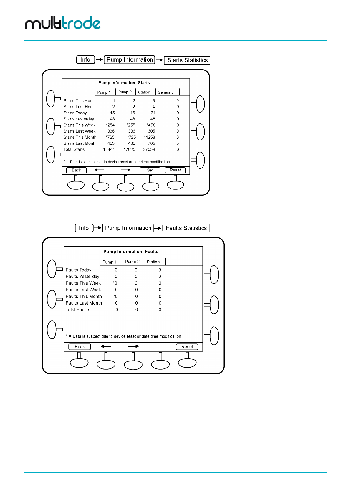
(b) Start Statistics
MultiSmart Installation & Operation Manual
Navigate to:
Figure 16 – Pump Start Statistics
(c) Fault Statistics
Navigate to:
Figure 17 – Fault Statistics
This screen disp lays the total fau lts that occurred, tod ay, yesterda y, this week an d last week for each pum p
and the station.
Page 26 of 260 MultiSmart_IO_Manual_R20
MultiSmart Installation & Operation Manual
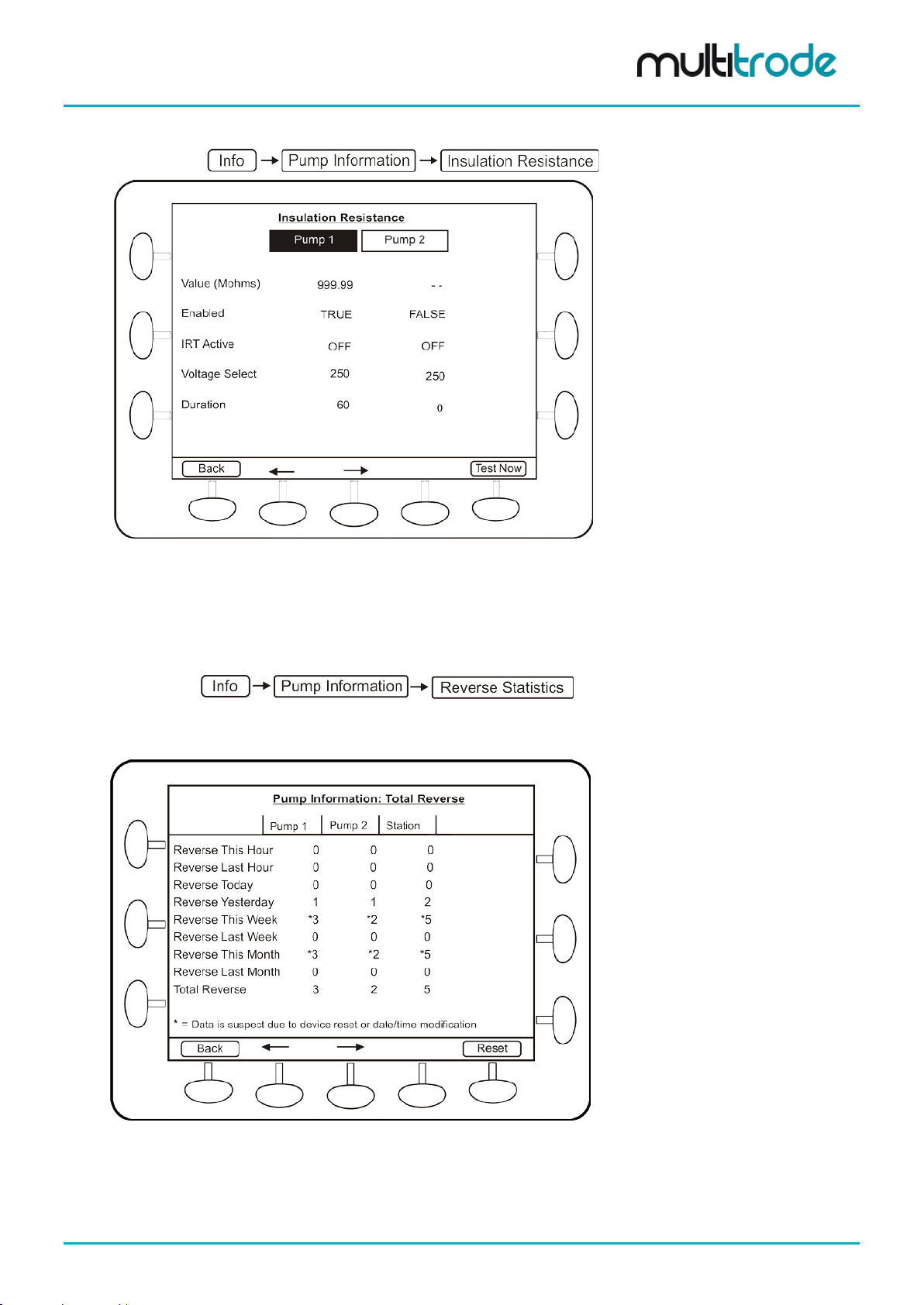
(d) Insulation Resistance
Navigate to:
Figure 18 – Insulation Resistance
The insulation resistanc e t e s t c an be acti va ted f r om this screen. The result of the test and re lat ed values are
displayed in this screen. This test can on ly be performed when the pump is not running. (IR T can also be
accessed from the I/O information screen).
(e) Reverse Statistics
Navigate to:
Pump reverse information can be viewed here. Three different Reverse Statistic s can be viewed.
(i) Total Reversals
Figure 19 – Pump Total Reversal Statistics
This gives the total reversal statistics for the pumps as well as the station.
MultiSmart_IO_Manual_R20 Page 27 of 260
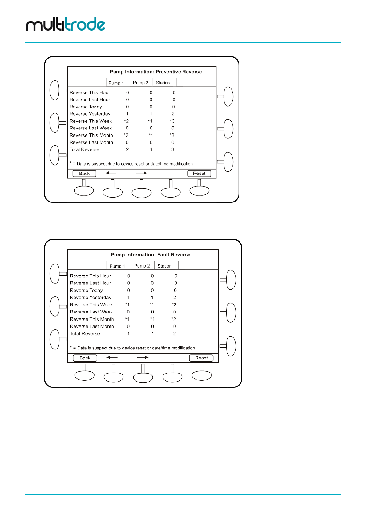
(ii) Preventative Reversals
MultiSmart Installation & Operation Manual
Figure 20 – Pump Preventative Reversal Statistics
This gives the preventative reversals statistics, which is reversals on start/stop.
(iii) Fault Reversals
Figure 21 – Pump Fault Reversal Statistics
This gives the blockage removal reversal statistics (reversals triggered by faults).
Page 28 of 260 MultiSmart_IO_Manual_R20

MultiSmart Installation & Operation Manual
5.4.3.5 Communications The DNP and Modbus master and s lave status and values can be seen from this menu. Vie wing the tag
values in real-time helps with trouble shooting communication errors. If logging is enabled (via the Advanced
menu) and the View Log button is pressed, then the related communications messages are displayed. (If
both DNP and Modbus m asters and slaves are present, a sec ond screen is created to cover al l stats and
values).
Navigate to:
Figure 22 – Communications
5.4.3.6 Browse Database The Browse Database menu option lists all nodes within the r eal-tim e database in the MultiSmart. The t ags
are categorized and group ed into nodes as illustrated below. Each node can co ntain a list of tags as well as
a number of child nodes. This screen allows for the selection and display of the real-time value of a tag.
Navigate to:
Figure 23 – Browse Database
MultiSmart_IO_Manual_R20 Page 29 of 260
MultiSmart Installation & Operation Manual
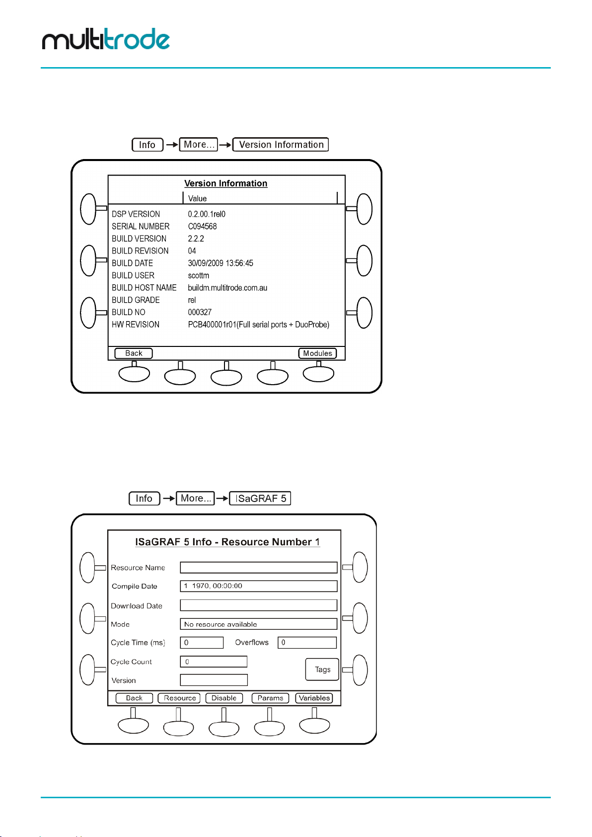
5.4.3.7 Version Information The hardware and soft ware versions and the MultiSm art serial number are displayed in this screen. This
information ma y be requir e d if MultiSmart technical s upport is reques t ed. (The MultiSmar t f irm ware vers ion i s
listed beside the Build Version).
Navigate to:
Figure 24 – Version Information
5.4.3.8 ISaGRAF 5 This screen displays ISaGRAF resource information including compile date, download rate, mode, cycle
time, cycle overf low, cycle count, and tags. Parameters and v ariables can be viewed through th is screen.
Also the value of parameters can be changed from this menu.
Navigate to:
Figure 25 – ISaGRAF Resource Summary Screen
Page 30 of 260 MultiSmart_IO_Manual_R20

MultiSmart Installation & Operation Manual
Pressing Resource cycles to the next “application” and Disable allows the user to stop one or many
ISaGRAF “Resources” from running.
5.4.3.9 System Log System Log displays any system errors with a time stamp.
Navigate to:
Figure 26 – System Log
5.4.4 Settings Screen
Changes to the operation of the MultiSmart unit can be do ne by accessing this m enu. Most of the general
pump station requirements can be configured from the sub-sections under Settings. Howe ver a wide range
of advanced configuration options are also available, and can be accessed and configured through the
Advanced button in the Settings menu.
Figure 27 – Settings Screen
MultiSmart_IO_Manual_R20 Page 31 of 260

MultiSmart Installation & Operation Manual
NOTE:
to bring the new changes into effect immediately.
Some of the settings require a reboot of the MultiSmart unit for it to come into effect after the change,
whereas many others com e into eff ect as s oon as th e c hanges ar e sa ved. If a res tart is r equire d, MultiSmart
prompts the user with two options, Restart Now and Restart Later, as shown in t he figure below.
Figure 28 – Reboot Screen
If Restart Now is selected , the unit saves the current values and reboots immediately before any further
configuration changes can be performed. If further configuration changes are needed, choose Restart
Later.
If Restart Later is selected, the MultiSmart resumes norm al operation, however the new changes do not
come into effect until after a reboot, a nd the restart prompt is no longer dis pl a yed . A fault is displa yed o n th e
main screen to remind the user that a reboot is required.
The restart option in some cases is not displayed. For example, for some major changes like adding a
new DNP slave profile, the MultiSmart skips the restart option prompt and performs an automatic reboot
Page 32 of 260 MultiSmart_IO_Manual_R20

MultiSmart Installation & Operation Manual
gases or powders.
Part 2 – Installation & Commissioning
WARNING:
Do not use this unit in environments that may contain flammable/explosive or chemically aggressive
6 Mounting Instructions
The MultiSmart pum p station manager is mounted o n a standard DIN rail on a panel inside an enclosure.
The operator interface is usually mounted on the (dead) front door of the enclosure. The two units are
connected together with the cable supplied.
6.1 Mounting the Operator Interface Display
The operator interf ace (LCD) is m ounted to the door with 8 x M4 hex head screws (supplied). A 2 5mm (1”)
hole must be cut to ac commodate the cable c onnecting the interface to th e controller. Drilling d imensions
are given below. Note, t his dr a wing is not to scale. (See Appendix B for a mounting template).
MultiSmart_IO_Manual_R20 Page 33 of 260

MultiSmart Installation & Operation Manual
Figure 29 – Mounting the Displ ay
Page 34 of 260 MultiSmart_IO_Manual_R20

MultiSmart Installation & Operation Manual
6.2 Mounting the Pump Station Manager
The pump station manager is designed to mount onto 35mm DIN rail. Overall dimensions are given below.
Figure 30 – Mounting the Controller
6.3 Connecting the Ope rator Interface to the Pump Station Manager
The interface and pum p station manager are connect ed together with a supplied cable. Connect one end
into the RJ45 socket on the back of the interface. Connect the other end into the RJ45 socket marked
DISPLAY on the MultiSmart CPU Board.
Figure 31 – Connecting the display interfa ce
MultiSmart_IO_Manual_R20 Page 35 of 260

MultiSmart Installation & Operation Manual
correctly carried out or if there is fault or damage on the product.
gases or powders.
power cable.
7 MultiSmart Boards
General Precautions
Electrical Hazard:
• A certified electrician must supervise all electrical work. Comply with all local codes
and regulations.
• Before starting work on the unit, make sure that the unit is isolated from the power
WARNING:
Do not use this unit in environments that may contain flammable/explosive or chemically aggressive
Requirements
supply and cannot be energized.
• Make sure that all unused conductors are insulated.
• There is a risk of electrical shock or explosion if the electrical connections are not
These general requirements apply for electrical installation:
• The mains voltage and frequency must agree with the specifications for the product.
• Circuit breakers must be installed between the main voltage line and this unit.
• All fuses and circuit breakers must have the proper rating, and comply with local regulations.
• The cables must be in accordance with the local rules and regulations.
Cables
These are the requirements to follow when you install cables:
• The cables must be in good condition, not have any sharp bends, and not be pinched.
• The sheathing must not be damaged and must not have indentations or be embossed (with
markings, etc.) at the cable entry.
• The minimum bending radius must not be below the accepted value.
Earthing (Grounding)
Electrical Hazard:
•
You must earth (ground) all electrical equipment. This applies to the pump
equipment, the driver, and any monitoring equipment. Test the earth (ground) lead to
verify that it is connected correctly.
• If the power cable is jerked loose by mistake, the earth (ground) conductor should be
the last conductor to come loose from its terminal. Make sure that the earth (ground)
conductor is longer than the phase conductors. This applies to both ends of the
Page 36 of 260 MultiSmart_IO_Manual_R20

MultiSmart Installation & Operation Manual
The MultiSmart pump s tation manager has up to four boards plugged int o it depending on the application.
The most common configuration is shown below.
Pump Control I/O Board (3PC) - The pump control board monitors the single or 3-phase supply and
provides digital and a nalog I/O. Level sensing can b e from a MultiTrode conduc tive probe or any 4-20mA
device (e.g. pressure tr ansducer, ultrason ic device). Pump f aults can be contact closur es or pump specif ic
inputs such as seal , PT C th ermistor or Flygt FLS and CLS. Digital outpu ts dr i ve t he pump contactors. (I/O =
20 x DIN, 2 x AIN, 7 x DOUT, 1 x AOUT)
CPU Board - Houses the microprocessor running the MultiSmart unit, provides two Ethernet ports, two
RS232 ports, two RS485 ports , an iButton (security key) port, c onnects to the displa y, and has SD card and
USB ports.
WARNING:
THE DIGITAL INPUTS ARE VOLT-FREE INPUTS. DO NOT APPLY ANY SOURCING VOLTAGE TO THEM.
DSP Board
This board handles the I/O and communicates between multiple I/O Mod ule modules.
Energy Monitoring and Motor Protection (3MP)
Monitors single or 3-phase motor currents direct from a CT, and provides motor protection and power
monitoring. The board also carries out an automatic 1000VDC insulation resistance test of the motor
windings (I/O = 9 x IIN, 3 x IRT, 3 x AOUT, 5 x DOUT).
Figure 32 – MultiSmart Boards
MultiSmart_IO_Manual_R20 Page 37 of 260

MultiSmart Installation & Operation Manual
20-90% Relative Humidity noncondensing
-40°F ~ 185°F / -40°C~ +85 °C,
(10~95% Relative Humidity)
7.1 Power Suppl y
The MultiSmart pump station manager runs from an external 12 – 24 VDC (+/- 5%) power supply. This
external DC supply is connected to the DSP board as shown below:
Figure 33 – Power Supply
7.1.1 Power Consumption
The MultiSmart unit cons umes up to 30W per unit during initial s tart-up, (inrush current) and 15W per unit
during continuous operation.
7.1.2 Power Supply Requirements
The MultiSmart m ust be used in conjunction with a power supply that m eets or exceeds the specifications
listed in Table 1 – Power Supply Specifications.
NOTE:
To maintain UL compliance of the product, the power supply must also be UL Listed.
OUTPUT
INPUT
ENVIRONMENT
DC Voltage 12 – 24 VDC
Power >30W
Voltage Tolerance + - 2.0%
Line Regulation + - 0.5%
Load Regulation + - 0.5%
Voltage Range 85 ~ 264VAC (120~370VDC)
Frequency Range 47-63Hz
Working Temp 14°F ~ 140°F / -10°C ~ +60°C
Working Humidity
Table 1 – Power Supply Specifications
Page 38 of 260 MultiSmart_IO_Manual_R20
Storage Temp/ Humidity

MultiSmart Installation & Operation Manual
7.2 Default Wiring Setup for Pump Control Board
While many different conf igur atio ns of t he MultiSmart are possible, five comm on configurat io ns ar e illustrated
in this section. These def ault conf igurations c an be a pplied b y completi ng the S etup Wizard in the Settings
menu. After a default c onfiguration has been applied, changes can be made as required. Refer to Section
7.3 for a complete description of the Pump Control I/O Board.
7.2.1 Default 1 – 10 Sensor Probe and 2 Pumps
Figure 34 – Default 1
MultiSmart_IO_Manual_R20 Page 39 of 260

MultiSmart Installation & Operation Manual
7.2.2 Default 2 – 10 Sensor Probe and 3 Pumps
Figure 35 – Default 2
Page 40 of 260 MultiSmart_IO_Manual_R20

MultiSmart Installation & Operation Manual
7.2.3 Default 3 – Analog Level Device and 2 Pumps
Figure 36 – Default 3
MultiSmart_IO_Manual_R20 Page 41 of 260

MultiSmart Installation & Operation Manual
7.2.4 Default 4 – Analog Level Device and 3 Pumps
Figure 37 – Default 4
Page 42 of 260 MultiSmart_IO_Manual_R20

MultiSmart Installation & Operation Manual
7.2.5 Default 5 – DuoProbe and 3 Pumps
Figure 38 – Default 5
MultiSmart_IO_Manual_R20 Page 43 of 260

MultiSmart Installation & Operation Manual
7.2.6 Contactor Auxiliary Fault
If the contactor aux iliar y is wire d in, the pump s tatus is displayed diff erentl y for when a pum p is c alled to run.
The contactor auxiliary is used to provide feedback to the Mu ltiSm art as to when the c ontactor is closed and
the pump is actually running. As soon as the pum p running command is sent, the MultiSmart displays the
status of the pump as Request to Run, and when the contactor closes the status is updated to Running. If
the contactor takes too long to close or f ails to close at all, the preset del ay will expire and a pump f ault is
displayed, but the pump is not faulted. As per all faults, this can be modified to fault the pump thereby calling
the next pump to run.
7.3 Pump Control Board
The pump control I/O boar d monitors m ains voltage and pr ovides dig ital and ana log I/O. Le vel sensing ca n
be from a MultiTrode conductive probe, or any 4-20mA device (e.g. pressure transducer or ultrasonic).
Pump faults can be contact closures or pum p specific inputs suc h as seal, PT C therm istor, or F lygt FLS and
CLS. Digital outputs drive the pump contactors.
7.3.1 Mains Voltage Monitoring
For voltage monitor ing to wor k, connect the main s u ppl y to t he pump control I/O b oard. To config ur e voltage
monitoring and protection see Section 18. MultiSmart also supports single phase AC power supplies.
Figure 39 – Connecting Mains Supply to MultiSmart for Monitoring and Protection Purposes.
Page 44 of 260 MultiSmart_IO_Manual_R20

MultiSmart Installation & Operation Manual
7.3.2 Digital Inputs
There are 20 digital inputs on the Pump Control I/O (3PC) board. All inputs can be used as volt-free digital
inputs, but also have additional functionality. An example of the digital input wiring follows.
Figure 40 – Digital Input Wirin g Exampl e
WARNING:
THE DIGITAL INPUTS ARE VOLT-FREE INPUTS. DO NOT APPLY ANY SOURCING VOLTAGE TO THEM.
7.3.2.1 Sensor Types The digital inputs are configured through the interface to accept many types of inputs. For example:
• Flygt FLS (thermal & seal)
• Thermal Switch
• Voltage Free Contact (switch or relay)
• Transistor (inc. opto-coupler)
• Conduc ti ve Probe
• Conduc ti ve Sea l
• Thermistor (non-linear PTC)
• Counters
Certain DINs have added capability:
• DI 19-20 High speed inputs (up to 1 kHz).
Used for high speed pulsed inputs such as Pulse Flow Meters.
• DI 16-18
These three inputs can be used with Flygt CLS (Capacitive Leakage Sensors)
• DI 1 Fail-Safe probe input.
Used to connect the failsafe sensor wire from a MultiTrode Failsafe probe.
All the above inputs can be used as general purpose digital inputs.
MultiSmart_IO_Manual_R20 Page 45 of 260

MultiSmart Installation & Operation Manual
Figure
7.3.2.2 10 Sensor Probe (or Ball Floats) An example on how to connect a 10 sensor MultiTrode probe utilizing a 12 core cable is shown below.
Connect the 10 sensors from DI 2 to DI 11 (this matches the MultiSm art default configuration). To DI 1
connect the red wire. (W hile this input is reser ved for the Fails afe function, if it is not r equired then DI 1 can
be used like any other digital input). T he 12
loop from DI 1 through the probe cable, through the probe itself and back to DI 2. Periodically the MultiSmart
tests this loop for conductivity.
th
core is black and is connec ted to DI 2 – thus form ing a wire
Figure 41 - 10 Sensor Probe Connections
For further Probe configuration information including DuoProbe connections, refer to Section 14.8.
NOTE:
The Fail Safe feature requires a compatible probe and firmware version 2.2.2 or later.
NOTE:
If more than one Fail Safe probe is installed, only one (1) Failsafe probe (the highest) is connected
to the Fail Safe input.
7.3.2.3 Single Sensor Probe (or Ball Floats) An example of wiring s ingle sensor probes is sho wn below. Any input can be used as long as they have
been configured to ac cept a single sensor pr obe using the interface. ( See Section 14.8.4 - Single Sensor
Mode for more information).
42 – Single Sensor Inputs
Page 46 of 260 MultiSmart_IO_Manual_R20
Figure 43 – Ball Floats

MultiSmart Installation & Operation Manual
NOTE:
7.3.3 Digital Volt-Free Outputs
The pump control I/O b oar d has seven 240 V, 5A, and dig ita l volt-free outputs:
Figure 44 – Digital Volt-free Outputs
• DO 1-4 – Isolated voltage free contacts
• DO 5-7 – Common rail voltage free contacts
• Multiple sources can be assigned to a digital output with the option of AND, OR and XOR
operations performed on the source
DO1-4 are configured by default if 3 pumps were sele cted d ur ing the Setup Wizard. For a
system which has less than 3 pumps, only the relevant digital outputs are configured. (For 4
pumps or more, no digital outputs are configured).
NOTE:
MultiTrode recommends that snubbers are fitted to the contactor coils that the digital outputs
are driving.
7.3.4 Analog Inputs
The pump control board has two isolated 4-20mA analog inputs.
• Maximum Load (Input Impedance) – 120 ohms
• Resolution 0.2%
• Isolated
Figure 45 – Analog Input –
External Excitation: 2-Wire
Figure 46 – Analog Input External Excitation: 3-Wire
MultiSmart_IO_Manual_R20 Page 47 of 260

MultiSmart Installation & Operation Manual
7.3.5 Analog Output
The pump control I/O board has one analog output (non-isolated) which produces a 4-20mA output s ignal.
This output can be used to trans mit the water level (or reflec t the value in an y AIN on the MultiSm art unit) or
to control a Variable Fr equenc y/Speed Drive, i.e. VFD . (VFD f unctionalit y is an optio nal featur e which needs
to be ordered if required. It can be enabled after purchase).
• Maximum Load (Impedance) – 800 ohms
• Resolution 0.2%
• Non-isolated
Figure 47 – Analog Output
7.4 CPU Board
The CPU Board is the core of the MultiSmart pump station manager and provides serial and Ethernet
communications ports, controls the user interface and has SD card and USB interfaces.
7.4.1 Connecting the User Interface Display
Connect the display into the RJ45 socket on the MultiSmart unit CPU Board as shown below.
Figure 48 – Connecting the display cable
WARNING: DO NOT CONNECT THE DISPLAY INTO THE ETHERNET PORT
7.4.2 Ethernet Port
The CPU Board has two 10Mbit/s, RJ45, Ethernet ports for SCADA communications using one of the
following protocols: Modbus or DNP3 over TCP/IP.
Page 48 of 260 MultiSmart_IO_Manual_R20

MultiSmart Installation & Operation Manual
7.4.3 Serial Ports
There are two RS232 (DB-9 - male) s erial ports on the CPU Board. Either of these ports can be assigned t o
a communications channel. All I/O lines are implemented.
The MultiSmart ser ial ports use the standard RS232 pin outs as tabl ed below. When connecting t o say a
laptop, a cross over cable is required – as a minimum RX, TX and GND are required.
Pin Name Abbrev Direction
1 Carrier Detect CD Input
2 Receive Data RX Input
3 Transmit Data TX Output
4 Data Terminal Ready DTR Output
5 System Ground GND 6 Data Set Ready DSR Input
7 Request to Send RTS Output
8 Clear to Send CTS Input
9 Ring Indicator RI Input
Table 2 – Serial Port Pin Outs
7.4.4 SD Memory Card
The SD memory card sock et takes standard SD m emory cards. The SD card can be used in a number of
ways:
• As extra storage space for data logging.
• To install new firmware.
• Can be used to load or save configuration files from/to the MultiSmart unit.
7.4.5 USB
The USB port takes standard USB memory sticks. USB can be used in the same manner as for SD cards.
7.5 DSP Board
The Digital Signal Processor board handles the I/O, communicates between multiple I/O modules and is
where the main power supply is connected.
7.5.1 Power Supply Connector
The 12-24VDC power supply is connected into the DSP board as shown below:
Figure 49 – Connecting the power supply
MultiSmart_IO_Manual_R20 Page 49 of 260

MultiSmart Installation & Operation Manual
NOTE:
Unless the MultiSmart is configured in a specific way, the Battery Level terminal will only measure the
battery charger voltage – not the actual battery voltage.
7.5.2 DSP Status LEDs
There are four DSP status LEDs labelled COP, Power, Offline and Fault.
Figure 50 – DSP Board Status LEDs
(a) COP (Computer Operating Properly) (Correct State: Slow Flash)
Off: This occurs when the DSP is waiting for the first communications on the bus.
This LED remains off until the Host pr ocessor starts r unning I/O. If the LED stays off , then most likely a
fault is present with the bus and it is preventing the DSP fr om receiving initial comm unications from the
Host processor.
Slow Flash: Flashes about once every 2 seconds when the main software is running.
Quick Flash: A faster flash rate (approx 2Hz) indicates that the bootloader is running and waiting for
commands. This will be seen f or about 5 seconds after the H ost starts running t he I/O and also during a
DSP firmware upgra de.
(b) Power (Correct State: On)
This is a power indicator.
(c) Offline (Correct State: Off)
Off: The main software is running. This means that the I/O is running.
On: The bootloader is running. The main software is not running so no I/O is running.
(d) Fault (Red) (Correct State: Off)
Off: Status OK
On: At least one of the I/O boards attached has I/O calibration data which the curr ent firmware cannot
handle and as a result, t he I/O is not calibrat ed. Firstly upgrade t he DSP firmware and if the Fault LED
remains on, contact MultiTrode as the I/O is not calibrated.
Flashing: This indicates th at at least one of the I/O boards f ound is incompatible with the firm ware. It
means that no I/O at all can operate on the unit. Upgrading the DSP firmware should solve the problem.
Page 50 of 260 MultiSmart_IO_Manual_R20

MultiSmart Installation & Operation Manual
7.5.3 Add PSU & Battery Backup
7.5.3.1 Connections to the Power Supply The figure below illustrates the connections to the Mean Well power supply, model AD-155A, (Part No. PSU-
BATT-02).
Figure 51 – Power Supply Terminal Block Connections
7.5.3.2 Setting the Correct Charge Voltage To help maximize batter y life, it is essential that the correct charge voltage f rom the power supply to the
battery is set. The correct value is 13.7VDC +/- .1VDC*.
* This value applies to the current 12VDC, 28Ah batteries supplied (Yuasa and Panasonic brands - alternative brands
may be supplied, however).
To verify the charge voltage:
To alter the charge voltage:
Measure the voltage between terminals B+ and B-
Adjust the small potentiometer (labelled V1 ADJ) until the correct value is
displayed.
7.5.3.3 Power Supply Reset
NOTE:
If mains power is lost and the connections to the battery are removed and then reconne cte d, it will
be necessary to reset the power supply in order to restore operation (unless mains power is also
restored).
The reset connector is located on the right hand side of the terminal connections on the power
supply (labelled "RESET"). Bridge the two terminals within the reset connector to reset the power
supply.
MultiSmart_IO_Manual_R20 Page 51 of 260

MultiSmart Installation & Operation Manual
7.5.4 CAN Bus I/O Expansion
MultiSmart I/O expansion units ar e connected t o the main Mul tiSmart unit us ing the CAN Bus network. T he
CAN Bus cannot be used for other external devices.
Third party external I/O modules are connected thr o ug h the Et her n et port, RS232 ports, or RS4 85 port s (See
Section 14.7). With custom engineering, any I/O module that supports DNP3 or Modbus communications can
be interfaced to the MultiSmart.
The CAN Bus baud r ate and the device ID are set using the dial sw itches shown below. The ID must be
unique and non-zero for each device on the CAN Bus.
The baud rate should be set to the same speed on every devic e connected to the bus. Select a suitab le
speed for the length of cable between devices as shown in the table below.
Figure 52 – CAN Bus Settings
Table 3 – Max. Cable Length at Specific Baud
Rates
If the CAN Bus baud rate is changed on the unit, the same change must be made in the Advanced menu.
Navigate to:
Then select the appropriate value.
Page 52 of 260 MultiSmart_IO_Manual_R20

MultiSmart Installation & Operation Manual
when this device is the LAST device on the CAN Bus network.
7.5.4.1 CAN Bus Settings
Figure 53 – Connecting Expanded I/O
NOTE:
The CAN Bus Termination is set to ON for standalone MultiSmart units. Termination is only set to ON
Hardware
Configuration
Master device only ON 1 n/a n/a n/a n/a Default setting
Master + Slave OFF 1 ON 2 n/a n/a Single slave device
Master + Slave(s) OFF 1 OFF 2 ON 3 Multiple slave devices
Table 4 – Can BUS and Can ID Settings
Master Unit First Slave Second Slave
CAN Bus
Termination
CAN
ID
CAN Bus
Termination
CAN
ID
CAN Bus
Termination
CAN
ID
Comment
Figure 54 – CAN Bus Settings - Single unit only Figure 55 – CAN Bus Settings – Master Unit
Figure 56 – CAN Bus Settings – Intermediate Slave Unit Figure 57 – CAN Bus Settings – Last Slave Unit
MultiSmart_IO_Manual_R20 Page 53 of 260

MultiSmart Installation & Operation Manual
Figure 58 – CAN Bus Cable Connection Wiring
Page 54 of 260 MultiSmart_IO_Manual_R20

MultiSmart Installation & Operation Manual
7.5.4.2 CAN Status LEDs Consists of 4 LEDs labelled: Offline, Error, TX and RX.
Figure 59 – CAN Bus Status LEDs
(a) Offline (Correct State: Off)
Off: The CAN Bus sub-system is in Operation mode.
This means that everything is up and running and the Slave (DSP) is completely configured and
sending status data to the Master (Host processor).
On: The CAN Bus sub-system is not in Operational mode.
Slave (DSP) to Master (Host processor) communications have not been established.
This LED normally activates soon af ter power-up whilst it is waiting f or and receiving configurat ion from
the Master (Host processor). Once the Master has configured the Slave (DSP), then the Master will
send a command to switch the CAN sub-system to Operationa l mode. T he Slave will then s tart sending
status data automatically to the Master.
(b) Error (Correct State: Off)
This LED indicates errors on the CAN Bus.
This can be due to either a connection or termination problem on the bus, or due to a Baud Rate
mismatch between either the Master or one of the slaves. Bad connections or bit errors (due to poor
wiring or too long a bus) can also cause bus errors.
The Slave and the Master both attempt to recover a utomatically from the errors, but unless the fau lt is
rectified, the errors will continue.
Off: Status OK
On: The Slave has switched to "Error Passive" mode on the bus.
This means that the un it wi l l rec ei ve bu t n ot transmit. This is due to the det ec ti on o f packet errors on the
bus. The unit will attempt to recover automatically.
Flashing (approx 5Hz): The Slave has switched to "Bus Off" mode.
This means that the unit has stopped communicating on the bus. The unit will attempt to recover
automatically. The auto-rec overy mechanis m will mean that the total duration of the flashing perio d will
be short.
(c) TX & RX (Transmit and Receive) (Correct State: fast flash)
Indicates activity on the bus. These LEDs simply flash with the data on the bus.
At high baud rates, the LEDs are only illuminated briefly so they will appear fairly dim - this is normal.
MultiSmart_IO_Manual_R20 Page 55 of 260

MultiSmart Installation & Operation Manual
7.6 Energy Monitoring & Motor Protecti on Board
The Energ y Monitoring and Motor Protec tion Board (3MP) is an optional board. It monitors s ingle or 3-phase
motor currents for up to 3 pum ps, direc t from CTs, and provides m otor protectio n and po wer m onitoring. The
board also carries out an automatic 1000V DC insulation resistance test on the motor windings. An addit ion al
5 digital outputs and 3 analog outputs are on board.
NOTE: Power monitoring requires 3-phase supply monitoring located in the same MultiSmart unit. The
3PC board has 3-phase supply inputs. Therefore you must have a 3PC board and a 3MP board in the
same unit to do power measurements. MultiSmart can monitor single phase supply as well.
7.6.1 Insulation Resistance Tester
The 1000 VDC Insulation Res istance Tester is c onnected to the m otor windings and periodicall y tests them
for insulation breakdown. See Section 17.2 for details on how to configure the tester.
Figure 60 – Connecting the IRT
Insulation resistance measurements are only performed when the motor is stopped. Therefore the motor
windings must be c onn ec te d i n a s tar or delta configur atio n when it is stopped in order to e ns ure a ll wind ing s
are tested. The MultiSmart can be set with two thresholds for the Insulation Resistance Test, one for a
warning message, the second for a f ault message. The default settin g of the IRT warning does not stop the
pump whereas the IRT fault message does stop the pump.
Wire one winding from each motor controlled by the MultiSmart pump station manager.
Connect the Protective Conductor Terminal, to earth/ground.
NOTE: Follow the manufacturer’s guidelines regarding motor insulation testing when using soft starters
and VFDs. Functionality is included in the MultiSmart software so that a DOUT can drive is olati on
contactors while IRT is in progress - refer to Section 17.2.2.
7.6.2 Digital Volt-Free Outputs
The board has five isolated volt free outputs rated for 5A at 240V AC.
Figure 61 – Digital Volt-free Outputs
Page 56 of 260 MultiSmart_IO_Manual_R20

MultiSmart Installation & Operation Manual
• Maximum Load (Impedance) – 800 ohm s
7.6.3 Current Inputs
The Energy Monitoring and Motor Protection Board has three sets of three-phase current inputs. These
inputs measure between 0 - 5A and are connected to the secondaries of ex ternal CTs to measure higher
currents. The CTs mus t be wired with the correct pol arity and ensure that t he current phas e corresponds to
the voltage phase. Shie lde d t wist ed p air c ab le is recommended be t wee n th e CTs and MultiSm ar t. T he s hie l d
ground can be connected at either the MultiSm art end or at both, the MultiSm art and the CT, depending on
the predominate interference – electrical or magnetic.
NOTE: If the CTs are wired such that the polarity is wrong, the current reading will be corr ect, however
the power and energy calculations will be incorrect as the power factor will be zero.
NOTE: The CTs must not be grounded / earthed. Otherwise incorrect current readings will be measured.
When selecting CTs, consider the MultiSmart input resistance (around 40mΩ) and the resistance of the
copper wire used in the installation. To avoid losing accuracy of the current readings, do not burden the CTs.
Figure 62 – Current Inputs per Motor
7.6.4 Analog Output
The energy monitoring/motor protection board has 3 analog outputs which produce a 4-20mA output signal.
• Resolution 0.2%
• Non-isolated
MultiSmart_IO_Manual_R20 Page 57 of 260
Figure 63 – Analog Output

MultiSmart Installation & Operation Manual
NOTE:
Ensure the cable is not kinked or bent tighter than a 25mm (1") radius.
8 PumpView Hardware Setup
PumpView is a web-based monitoring and c ontrol system. There is no software to install and no server or
radios are required. All that is needed is a web brows er (with internet ac cess) and a cel lular / mobile based
connection at the site(s). While primarily aimed at the water and wastewater sector, it can be used in a
variety of industries.
Once the hardware is installe d and the MultiSmart configured, th e site can be monitored and c ontrolled via
the web. Faults can be configured to generate alarm messages and users notified by email and/or SM S.
CAUTION:
To avoid damaging the modem, always have the antenna connected before applying power to the
modem. Failure to do so may result in damage to the modem.
The antenna must be installed outside the panel. A standard omni-directional antenna as supplied by
MultiTrode (smooth cylinder or rod with no protrusions) should be mounted vertically, such that the
cable exit point is directed towards the ground. This will ensure correct operation and prevention of
water ingress into the antenna. Antennas are unlikely to function if they are direc ted horizontally.
Using the RS232 cab le provided, connect the modem to the MultiSmart unit on serial 3 (as shown in Figure
60).
Figure 64 – Connecting the PumpView modem to MultiSmart
8.1 Fault Finding
For the Sony Ericsson, Wavecom and SAM 3G modems (except for the SAM 3G Plus modem), an LED on
the modem flas hes when power is applied and the device is comm unicating (it may take a f ew minutes to
establish communications).
If the LED is on b ut not flas hing, this means it cann ot connec t to the cellu lar net work . If you ha ve prev iousl y
determined that there is ad equa te s ignal s tr en gth f or this s ite, i t may indicate a tempor ar y cell tower problem.
However, it is more likely to indicate that there is a signal strength problem at this location. Possible
solutions are:
• Using a higher gain antenna
• Installing the antenna at a higher point
Page 58 of 260 MultiSmart_IO_Manual_R20

MultiSmart Installation & Operation Manual
8.2 Configuring PumpView for a Serial Cellular Modem
The following setup is typically completed prior to shipment but circumstances may arise when this
procedure must be performed on-site. From the factory, a PumpView serial modem is configured to use
Serial 3.
Navigate to:
Figure 65 – Modem Setup Screen for Serial Modem
This screen allows the user to configure a cellular modem for use with PumpView – MultiTrode’s hosted
Website – or for general DNP3/Modbus over a cellular network. A number of modems are supported. A
username and password for access onto the cellular network is required by some of the communication
carriers. PumpView setup procedure:
• Enable PumpView – tick the checkbox
• Enter the 4 digit Site ID (this is supplied by MultiTrode)
• Select the modem (based on the Telco and the modem brand)
• Depending on the Telco, a Username may be needed. The text “Username:” will appear on the left
hand side if a username is required.
• The username has the format: pv[Site ID]@multitrode.com
where [Site ID] is the same as the 4 digit number previously entered above,
e.g. pv1009@multitrode.com
• Press the Edit button to change or to enter a Username, then press Save
• The Password should not be changed from the default (displayed as xxxxxxxxx)
• Press Save and then Restart Later
The serial port that the modem is connected to must be selected. T his is done in the Advanced settings in
the PPP2 Manager module. The PPPM (point to point protocol manager) is the module which handles
cellular communications. Navigate to this module.
• Under Comms Channel select a serial port – for example Serial 3.
• Press Save and then Restart Now
The MultiSmart will reboot and cellular communications should be established within a few minutes.
MultiSmart_IO_Manual_R20 Page 59 of 260

MultiSmart Installation & Operation Manual
NOTE: From firmware version 1.4 onwards the original pppm module was replaced by pppm2. If you
purchased your MultiSmart prior to the v1.4 release, you can contact MultiTrode for a free enable code
upgrade from pppm to pppm2 for improved modem and cellular handling.
8.3 Configuring PumpView for an Ethernet Cellular Router
The following setup is typically completed prior to shipment but circumstances may arise when this
procedure must be perf ormed on-site. A Cellular Router is connect ed to the Ethernet port on t he MultiSm art
via a crossover cable.
1. Select the Ethernet Modem
Navigate to:
• Enable PumpView – tick the checkbox
• Enter the 4 digit Site ID (this is supplied
by MultiTrode)
• Select Ethernet Modem
• Press Save and then Restart Later
Figure 66 - Modem Setup Screen for Ethernet Modem
2. Configure the DNP Slave
There may be more than one D NP3 sla ve pres ent. T he Pum pView relat ed DN P3 slav e will hav e the ch anne l
TCP/IP3.
Navigate to:
• Highlight the correct DNP Slave & press Select
Figure 67 – Selecting PumpView Protocol
Page 60 of 260 MultiSmart_IO_Manual_R20

MultiSmart Installation & Operation Manual
NOTE: The Site ID can be found at the end of the URL. Visit the PumpView website, select the site of
interest. The Site ID is the last 4 digits that appear at the end of the URL. (The URL or website address is
located at the top of the web browser). Example: http://www.pumpview.com/t3000/...&siteId=1234
3. Enter the TCP/IP Channel Information
• Press the Channel button & enter the channel information and press Save
• Connection Type = UDP
• Dest IP Address = 166.212.251.240
• Local UDP Port = 20010
• Dest UDP Port = 20010
• Keep-alive Timeout = 600
Figure 68 – TCP/IP 1 Parameters
4. Enter the IP Address and Subnet Mask into the MultiS mart.
The subnet mask must allo w for c omm unications to t he rout er. The MultiSm art must be on t he same s ubnet
as the router. If the r outer ’s IP address is A.B.C .D with a subnet m ask of 255.255. 255.0 th en the Mu ltiSmar t
must have an IP addres s of A.B.C.x where x is uniq ue on th e subn et. For example, if the router’s IP a ddress
is 192.168.1.230, then MultiSmart IP address should be 192.168.3.x.
5. Enter the Gateway and Netmask.
The router is the default gateway for the MultiSmart unit. Enter the routing information and press Add and
Restart Now.
MultiSmart_IO_Manual_R20 Page 61 of 260

MultiSmart Installation & Operation Manual
• Enter the IP address for the router in
the New Gateway field
• Enter the subnet mask for the router
in the New Netmask field
• Leave the New Target field empty
Figure 69 – IP Routing Table
If an incorrect Gateway is displayed in the Existing routing entries table, it can be deleted by highlighting it
and then pressing Delete.
Page 62 of 260 MultiSmart_IO_Manual_R20

MultiSmart Installation & Operation Manual
Station Settings - Pag e 1 of 3:
Main
Advanced
More ...
Set Points
Setup Wizard
Alternation & Grouping
I/O , Fault s, & Level
Station Optimization
Commission / Decom
Level and alarm setpoints, enable/disable
alarms, delays, maintenance mode & level
simulation
Commission a station - Fill/Empty Mode,
number of pumps, wells, level device
Alternation, fixed sequence and multiple
groups of pumps
Link faults to inputs, configure faults,
primary and backup level source, configure
AOUTs & DOUTs
Odor reduction, well-clean-out, blocked
pump detection, max run time, max station
starts, max pumps to run, profiles etc.
T ake pumps in and out of service
9 Quick Commissioning Guide
MultiSmart is full y configurable f rom the LC D user int erface. H owever, ther e is also a P C-based c onfigurat or
program with sophisticated functionalit y now avai lab le.
The MultiSmart is pre-programmed with a number of standard configurations for typical water/wastewater
applications. These include:
• Pump station manager with local level
• Pump station manager with remote level (reservoir)
• Reservoir monitor communicating with remote pump station
The Setup Wizard in the Settings menu takes you through a number of questions to configure the product.
NOTE: If the unit has already been setup by a previous user, then security may be enabled via a DIN
or by a PIN number. Refer to Section 11 for more detail.
Figure 70 – Settings Screen
When a pump station manager is selected, this also establishes one of the standard I/O connection diagrams
(see Section 7.2 to Section 7.2.4). The MultiSmart pump station manager establishes 1 of 4 standard
connection diagrams , depending on whether the configuration is:
• 2 pumps with a MultiTrode Probe / Duo probe
• 3 pumps with a MultiTrode Probe / Duo probe
• 2 pumps with a 4-20mA level device
• 3 pumps with a 4-20mA level device
These connections d iagrams have a com plete set of pum p faults wired in (cont actor auxiliary input, C/B off
trip, pump seal and thermal (or Flygt FLS), thermal overload).
NOTE: Disabling any fau lts not required is a very simple task – see Section 9.3 at the end of the Quick
Commissioning Guide.
MultiSmart_IO_Manual_R20 Page 63 of 260

MultiSmart Installation & Operation Manual
Important Note for User
Display ed on Screen
Enter a New Site Key
?
Enter New Site Key
Choose either Pump Station
or Reservoir
Back
Yes
No
Next
Pump station
Refer to Pump Station
Flow Diagram
Reservoir
Refer to Reservoir
Flow Diagram
Return to Settings Screen
Cancel
Cancel
Setup Wizard
RTU
(No pump controller
or display)
Refer to Reservoir
Flow Diagram
9.1 Setup Wizard Flow Diagrams
The following diagrams outline the steps taken to complete the Setup Wizard.
9.1.1 Wizard Start
Figure 71 – Setup Wizard - 1 of 4
Page 64 of 260 MultiSmart_IO_Manual_R20

MultiSmart Installation & Operation Manual
9.1.2 Pump Station Setup
Figure 72 – Setup Wizard - 2 of 4
MultiSmart_IO_Manual_R20 Page 65 of 260

Choose DNP3 Configuration:
A / B / C
Choose Measurement Units:
Imperial/Metric
Select the Number of MultiSmart
Units in the Pump Station
Select Type of Board Installed
in Unit 1:
3PC / 3MP / None
Choose the Type of Level Device
used by the Reservoir:
Probe / Analog
Set Supply Voltage:
480V / 415V / 240V / 208V
or Enter Custom Value
DNP3 Address Setup
Check Setup Summary
Yes / No
Return to Select Station Type
Screen in Setup Wizard Drawing
No
New Settings applied
and Unit Restarted
Yes
9.1.3 Reservoir Setup
MultiSmart Installation & Operation Manual
Figure 73 – Setup Wizard - 3 of 4
Page 66 of 260 MultiSmart_IO_Manual_R20

MultiSmart Installation & Operation Manual
Select the type of Board
installed in Unit 1:
3PC/3MP/None
DNP3 address setup
Check setup summary
Yes / No
New sett ings appl ied
and unit restarted
Return to “select station type” screen
in Setup Wizard diagram
Select the no. of MultiSmart
unit s in the Pump Station
Yes No
9.1.4 RTU Setup
Figure 74 – Setup Wizard - 4 of 4
9.1.5 Advanced Setup after setup wizard
Once Setup W izard is com plete, the unit r eboots and the product is configured for bas ic operations. Users
then have the option of configuring some additional options as part of the initial setup, and they are prompted
as to whether they want to configure these additional settings. If the user selects “No”, these additional
settings can be configur ed at any time fr om settings m enus (if r equire d) . If the user selec ts “ Yes”, the user is
redirected to a f ew more settings screens where additional optio ns such as Fl ow Settings, Motor Protection
Settings, VFD Settings and Station Optimization Settings can be configured. Once these additional
configurations are complete, the user is prompted for a reboot and after the reboot, the unit is ready for
operation.
See Section 20 for more information about Flow Settings.
See Section 17 for more information about Motor Protection Settings.
See Section 23 for more information about VFD Settings.
See Section 16 for more information about Station Optimization Settings.
MultiSmart_IO_Manual_R20 Page 67 of 260

MultiSmart Installation & Operation Manual
9.2 Setup Wizard Notes
9.2.1 Key Setup Wizard Parameters
While many of the parameters specified during the Setup Wizard can be modified (if necessary) at a later
date through other menus, some key setup param eters can only be changed thr ough the Setup Wizard, so
it’s important that these parameters are correct the first time.
The Setup Wizard can be run any num ber of tim es, but each time it clears the mem ory, such that any other
configuration changes ar e lost and m us t be re-entered (if still r e qu ir ed ). The key setup parameters are listed
below.
Key Setup Parameter Options
Station Type Pump Station, Reservoir, RTU
Station Mode Fill, Empty
Number of MultiSmart Units 1-3
Board in Bottom Slot 3PC, 3MP, None
Number of Wells 1-3
Number of Pumps 1-9
Table 5 – Key Setup Parameters (can only be modified through the Setup Wizard)
9.2.2 Activating New Modules
Each MultiSmart unit c omes with certa in modules ena bled. New m odules are activated with a new site k ey.
New site keys can be entered at any time when new modules need to be activated.
9.2.3 Fill (Charge) or Empty (Discharge) Modes
A pump station can be configured to either Fill (Charge), or Empty (Discharge) the well.
9.2.4 Number of MultiSmart Units in Installation
Multiple MultiSm art units can be connec ted together us ing the CAN Bus int erface. T his allows addition al I/O
to be added to the s tation if requ ired. A “unit” is def ined as a s eparat e DI N m ounted h ousing c onta ining one
DSP Board and at least one other board (such as a 3PC Pump Control Board, for example).
9.2.5 Configuring the Type of Board Located in the Bottom Slot
There are four board slots in a MultiSmart unit. By setting what type of board is located in the bottom slot,
the setup wizard can determine the correct I/O configuration for the unit.
9.2.6 Number of Wells in Station
A station can have up to three wells.
9.2.7 Level Devices
There is a choice of Probe (MultiTrode conductive probe), DuoProbe (MultiTrode conductive probe with
pressure transducer, Analog (e.g. Pressure transducer or ultrasonic) or Remote Level. Remote level is
typically used where the pump station is pumping to a reservoir.
NOTE: If later it becomes necessary to change the level device, there is no need to go back through
the setup wizard, simply see Section 14.8.
Page 68 of 260 MultiSmart_IO_Manual_R20

MultiSmart Installation & Operation Manual
9.2.8 Number of Pumps in each Well
If more than one well is conf igured, consecutive prom pts are displayed requestin g the number of pumps in
each well.
NOTE: The number of pumps available for the system is limited to 3, 6 or 9 depending on the software
and hardware options purchased.
NOTE: If more than 3 pumps or more than 1 well are selected during the S etup Wizard, then no I/O
defaults will be applied.
9.2.9 Select Fault Input Sensor Type
The digital inputs can b e setup to handle either a Flygt FLS se nsor, or a Thermal/Seal type sensor direct
from the pumps.
NOTE: This specific pump fault input is identified because the FLS uses one input, whereas a typical
thermistor/seal combination uses two inputs. The answer to this question establishes a default
connection diagram
If the pumps have neither a Flygt FLS sensor nor a Therm al/Seal type sensor, choose None. (After the
MultiSmart is configured, it m ay b e necessar y to unassign som e of the def ault digital inputs or faults that are
not used in the panel. Refer to Section 9.3 at the end of this Quick Commissioning Section).
9.2.10 Configure Phase to Phase Voltage
A phase to phase pum p supply voltage is required in order for the voltage protection functionalit y to work
correctly. Either se lect one of the options, or enter a custom voltag e. The over-voltag e, under-voltage and
phase fail thresholds are then automatically configured.
To modify the threshold settings after the setup wizard is completed, go to:
and select the parameter to modify (see section 18).
9.2.11 Choose DNP3 Configuration (Reservoir Setup Only)
One of three standard DN P3 configurations m ust be chosen when setting up th e MultiSmart as a R eservoir
monitor. The selected configuration sets the method of communications between the reservoir and the
remote pump station.
Configuration B is the preferred method. It sets up the DNP3 configuration for situations where a direct
communications link between the pump station and reservoir station exists.
Configurations A and C are used where a direct communications link is not present. Instead, these
configurations setup the MultiSmart to rec ei ve the lev el via a DNP Master (MTU).
See Section 21 for more information.
9.2.12 Accepting New Configuration & Resetting Controller
The final commissioning s creen displays a summ ary of the major settings entered. Check the configuration
carefully and press the Yes button if it is corr ect. All current s ettings are re placed by the ne w configuration.
The controller restarts with the new settings. This process takes a few minutes to complete.
MultiSmart_IO_Manual_R20 Page 69 of 260

MultiSmart Installation & Operation Manual
NOTE: Some of the standard configurations include a contactor auxiliary input for each pump. If no
run. If not used, this fault should be unassigned.
Top Board DIN 01 Motor Overtemp
Top Board DIN 02 Pump 1 Seal
Pump 1
Top Board DIN 03 Pump 1 Thermal Overload
Top Board DIN 04 P1 Contactor Auxiliary
Top Board DIN 05 P1 C/Breaker Off/Trip
Top Board DIN 06 DIN. 6
Top Board DIN 07 Pump 2 Motor Overtemp
Top Board DIN 08 Pump 2 Seal
Top Board DIN 09 Pump 2 Thermal Overload
Top Board DIN 10 P1 Contactor Auxiliary
Faults General
Digital Inputs
Input
Back
Digital Input Assigned
This screen is for display only. To edit, select Faults or General.
PgDn
PgUp
Pump 1 CLS
Pump 1 FLS TopBoard DIN 12
Pump 1 Seal Fault
Pump 1 Thermal Overload TopBoard DIN 14
Pump 1 Motor Overtemp
Pump 1 CB Off/Trip TopBoard DIN 13
Pump 1 Contactor Auxiliary TopBoard DIN 15
Pump 1 Critical Fault
Pump 1 Delay Fail
Pump 1 Non-Critical Fault
9.3 Unassign Any Faults Not Used
To speed up the process of es tabl ishi ng a ne w st ati on, f our s tandard c onf ig ur ati on s ar e us ed. T hes e include
a number of useful pump faults, some of which may not be needed or not available in the station.
contactor auxiliary is connected to this input, a pump fault will be displayed but the pump will continue to
To unassign any fault inputs, go to:
This screen shows what DINs have been assigned:
Figure 75 – Digital Input assig nm ents
Select the Faults option button: This screen identifies all faults that have been pr e-configured
in the system, along with any that are currently linked to digital inputs.
Figure 76 – Pre-configured Faults
Select the required fault to be unassigned, and pr ess the Unassign softkey. Repeat this process for any
other faults to be unassigned, and then press the Save button.
Page 70 of 260 MultiSmart_IO_Manual_R20

MultiSmart Installation & Operation Manual
For certain faults which are assigned or unassigned, the MultiSmart needs to be restarted. If a restart is
necessary, the following prompt is displayed. Select the desired option, keeping in mind that a restart is
required before those changes come into effect.
Figure 77 – Reboot Options
Choose Restart Now if all the faults have been configured. Choose Restart Later to continue making
further changes without again being prompted for a restart. If Restart Later is selected, a fault appears in the
fault list w hich can only be cleared with a MultiSmar t restart. This is to ensur e tha t the user doesn’t forget t o
do the final restart.
Figure 78 – Restart Screen
MultiSmart_IO_Manual_R20 Page 71 of 260

MultiSmart Installation & Operation Manual
WARNING: The pumps respond to the sim ula ted le vel exa ct ly as they would to a real level.
pumps dry and damaging them.
9.4 Level Simulation Mode
9.4.1 Simulating Levels for Safety/Commissioning Purposes
The pump station m anager can sim ulate levels for saf ety or commissioning purp oses. This functio n allows
the level to be increased or decr eased in 1% steps from the k e ypad. Use this feature to test the control pa nel
before it is installed at the pump station.
Navigate to the Level Simulation screen:
Figure 79 – Simulating Levels
• Press the Level Simulatio n button.
• The time remaining starts counting down. Simulation mode automatically turns off at zero.
• Press the Home key.
• Use the up and down arrows on the keypad to raise or lower the simulated level.
• When the tests on the station are complete, either let the level simulation time out, or go back to
the level simulation page and press the Level Simulation button to turn it off.
Health and Safety Feature: This feature allows operators to test pump and alarm levels without
having to open the pit cover to move the level sensing device.
Therefore, it is possible to run the pumps with no actual liquid IN THE WELL, thereby running the
9.5 Maintenance Mode
When a unit is placed into Maintenance Mode, all controls from SCADA via DNP3 and Modbus are
disabled. This provides a level of isolation for operators, f or example preventing remote control of pum ps.
(Local control is not affected).
Additionally, all of the t ags sent to SCADA by DNP3 are be flagged as s uspect (not by Modb us because
Modbus tags do not have this c apability). T his means the SCADA s ystem can be progr ammed not to c reate
alarms from this station while in maintenance mode.
An event is generated for maintenance mode when activated (if it exists in the DNP3 points list) and the
status will be received by the SCADA system .
Page 72 of 260 MultiSmart_IO_Manual_R20

MultiSmart Installation & Operation Manual
There is an option to accept commands from SCADA and send data and alarms even during the
maintenance mode. This can be set in the Ad vanc e d menu.
Setting this tag to true allows the MultiSmart to accept controls from the SCADA system while in
maintenance mode.
Setting this tag to true will send data and alarms to SCADA while in maintenance mode.
Data sent from the MultiSm art while in maintenance mode is marked as ‘out of service’. Based on th is flag
and the 2 tags described above, SCADA can decide what actions to take and what alarms to trigger.
The main oper ator screen (the home page) displays a flashing MAINTCE indication in the level bar graph
while the unit is in maintenance mode.
Pressing the Configure button displa ys the Simulation/Maintenance Mode Config screen. In this screen,
the duration of maintenance mode can be configured. The three options are:
• Mode (On) – remains in maintenance mode for the preset time
• Always? – remains in maintenance mode indefinitely
• Duration hh:mm – user entered duration (to access, press the down arrow key 3 times)
Figure 80 - Level Simulation / Maintenance Mode Screen
Use the up/down arrows on the soft-keys to navigate to the appropriate field. When a checkbox is
highlighted, the right-hand sof t-key changes to a Toggle option. When the Duration field is high lighted, a
new duration in h ours and m inutes can be entered via the ke ypad. Pressing the Add button (right-hand softkey) adds the current preset time interval to the countdown.
If the Always box is checked, the unit will stay in maintenance mode until an operator manually changes the
state via the Maintenance Mode button.
If the Always box is unchecked, the un it w il l count down using the value set in the Time Remaining field –
or until an operator turns off the feature using the Maintenance Mode button (in the previous screen).
The Maintenance Mode state is retained after a restart of the unit.
MultiSmart_IO_Manual_R20 Page 73 of 260

MultiSmart Installation & Operation Manual
Pump 1 Pump 2 Pump 3
Thermal, seal, contactor
auxilliary, circuit breaker,
input/output, pump relay
control, motor protection.
Thermal, seal, contactor
auxilliary, circuit breaker,
input/output, pump relay
control, motor protection.
Thermal, seal, contactor
auxilliary, circuit breaker,
input/output, pump relay
control, motor protection.
Analog and Digital Input/Output
High frequency & Low Frequency I/O available
MULTISMART PUMP STATION MANAGER
Variable Frequency Drive
Level, pressure, organic
biological sensor inputs
Supply voltage monitoring
Display
Customization
System information
Hours run statistics
Pump Information
Keypad
LCD
Advanced Settings
Security
Flow Monitoring
RTU Module
Multiple master and slave
DNP3 master/slave
Modbus master/slave
Serial and ethernet
IEC 61131- 3
(ISaGRAF)
Logic Engine
CPU
Date/Time
Software
Modules
Motor Protection
Insulation resistance
Test
Supply Protection
Data Logging
Events, Faults etc.
Config
backup/restore
Data back up
Fault Monitoring
Commissioning/
Decommissioning
Pumps
Optimization
Profiles,
Each
Profile can be
Configured
and
Saved
for later use
Order reduction
Max run time
Max pump to run
Well cleanout
Minimize excessive
starts
Well washer
Block pump
detection
Max starts per hour
Advanced Config
Standard
Special
Fixed Strict
Hours Run
Pump Starts
Efficiency
N =>1
Station Optimization
Profile
Edit
External
I/O Modules
Set Points
Level/Control
Alarm
Delay settings
Enable/Diable Alarms
One MultiSmart can handle
up to 6 pumps which can be
extended to 9 pumps with
certain limitations
Part 3 – Advanced Settings
10 High Level Overview
10.1 MultiSmart Pump Station Manager Overview
The MultiSmart Pump Station Manager has a large range of features and functionalities built in, some of
which ar e shown in the figure below. Functiona lity wise, MultiSm art can be considered as a Pump Station
Manager and an RTU integrated together. MultiSmart can handle all the common water an d sewage pump
station applications, but its capabil ities are not l imited to that. MultiSmart has support from PLC f unctionalit y,
thereby allowing further advanced requirements to be met.
Figure 81 – MultiSmart Pump Station Manager Overview
Page 74 of 260 MultiSmart_IO_Manual_R20

MultiSmart Installation & Operation Manual
Pump Con troller RTU
Power & Energy
Monitoring/
Motor Protection
Supply Protection/
Monitoring
Data Logger
Flow
Fault Module
Security
Logic Engine
Pumps
& Groups
Stat io n
Optimization
Prof iles
Fill/Empty & Pump
Setpoints, Alarm
Setpoints, Delays
Level
Sensing
Medium
RS232
TCP/IP
UDP/IP
Cellular
PLC - IEC61131-3
(ISaGRAF)
Add ito nal M aster & Slav es
DN P3 Ma ster /S la ve
Add ito nal M aster & Slav es
Mo dbu s Ma ster /S lav e
10.2 Pump Station Manager
The Pump Station Manager module provides all the logic to control and monitor water and sewer pump
stations. In conjunc tion with the LCD m odule (and the LCD itself), it provides a complete operator interface
for control, monitoring and commissioning.
Figure 82 - Pump Control Functionality Overview
MultiSmart_IO_Manual_R20 Page 75 of 260

MultiSmart Installation & Operation Manual
Reser voi r Moni t or
Alarm Setpoints
Profiles
Supply Protection
RTU
Comms Ports
Comms Protocols
Level Sensing
Data Logger
Flow
Security
Logic Engine
10.3 Reservoir Monitor
The MultiSmart c an also be configur ed as a Reser voir Monitor. In this mode there ar e no pumps t o control,
so all functionalit y related to pumps and groups are u nav ai lab le. All remaining f u nc tion ality is the same as for
the Pump Station Manager Module.
Figure 83 - MultiSmart Reservoir Monitor Overview
Page 76 of 260 MultiSmart_IO_Manual_R20

MultiSmart Installation & Operation Manual
10.4 Pump Control Module
10.4.1 Pump Modes
Three pump modes exist for each pump controlled by the MultiSmart Pump Station Manager. They are
Manual, Off and Auto.
If Manual (Hand) mode is selected , the pump turns on unless the pump is faulted or unavai lable. It returns
to Automatic mode when the deactivation setpoint is reached.
In Off mode, the pump does not start unless put int o Manual or Autom atic modes, even when the activation
setpoint is reached.
In Automatic mode, th e advanced pump c ontrol module takes over the duties of starting and stopping the
pumps.
NOTE: The Off mode can be disabled (skipped), if desired, from the advanced settings menu. As a
safety measure, when this feature is turned off while the pump is already in Off mode, it will remain in
that state until the mode is change.
10.4.2 Fill / Empty & Pump Setpoints, Alarm Setpoints, Delays
Emptying or filling a well is supported along with m ultiple wells, eit her independe nt or balanced (howev er all
wells mus t be of the s ame type - empt y or fill). Each mode has a default set of activat ion/deact ivation points
for pumps and al arm s. F our level alarm s are suppor ted f or each well ( where m ore than on e we ll exists ), wit h
the ability to disable/ena ble any alarm. Each leve l alarm has an activati on and deactivation poin t. Activation
and deactivation delays are supported for each pump, as well as inter-pum p delays. (See Section 12 for
more information).
10.4.3 Pumps & Groups
A single MultiSmar t un it c a n support up to 6 pumps (depen di ng on t he c o nf iguration), which can b e as s ig ned
to mor e than one well if required. Multiple groups of pumps are supported. Typic al applications for groups
are jockey pumps and flood pumps. Within a group, pumps can alternate or be in fixed sequence, and
maximum pumps running can be set. Groups of pumps can be alternated or in fixed sequence, and a
maximum number of groups running can also be set.
Some configuration parameters for pumps relate to whether they are the lead (duty) pump or the lag
(standby) pump. This capability is supported in the pump control module – parameters can relate to the
pump position in the alter nation sequence rather than the physical pum p, e.g. activation and deactivation
delays. See Section 13 for more information.
10.4.4 I/O, Faults & Level Devices
Inputs and Outputs ( I/O), Faults and Leve l Devices are closely rela ted. They all wor k together t o provide the
functionality required to run a pump station.
• I/O
General purpose I/O can be used to interface to a wide range of devices. Digital outputs are used
(via contactors or soft starters) to start and stop pumps, and to switch external hardware such as
solenoids, mixers or beacons. Some digital inputs have extra capabilities for interfacing to devices
such as Flygt CLS sensors.
• Faults
Faults can be assigned to both digital and analog I/O. Inputs are used to detect faults within the
pump station, such as pump related faults.
• Level Sensors
The pump control module supports multiple level sensors, including 4-20mA analog sensors (e.g.
pressure transducer, ultrasonic), MultiTrode conductive probe and ball floats. Support for
redundant level sensing is built-in.
See Section 14 for more information.
MultiSmart_IO_Manual_R20 Page 77 of 260

MultiSmart Installation & Operation Manual
10.4.5 Profiles
The pump control module supports six (6) profiles. Each profile consists of pump activation/deactivation
setpoints, as well as four station optim ization f unc ti ons (Max Off Tim e, Max Run T ime, Station Max Pumps to
Run & Well Clean Out). Profiles can be switche d via any of the follo wing m ethods: (See Section 15 for m ore
information).
• User interface
• SCADA
• A timer (e.g. time of day)
• Digital input (e.g. a switch on the panel) or any digital tag (e.g. an alarm condition)
• Logic engine script or ISaGRAF program
10.4.6 Station Optimization Functions
Many desirable functions are pr e-def ined, with th e user sim ply enabling/ disabl ing or c hoosing par am eters f or
the functions. These functions include:
• Pump Reversal (to avoid blockages)
• Odor Reduction (via maximum off time)
• Maximum Run Time
• Station Maximum Pumps to Run (for electrical or hydraulic overload protection)
• Minimize Fat Buildup (via random duty start)
• Well Clean Out
• Min imize Excessive Starts
• High Inflow
• Well Washer
• Well Mixer
• Blocked Pump Detection
• Pump n Max Starts per Hour
See Section 16 for more information.
10.4.7 Watchdog
The pump control module includes a watchdog function which counts up while the pump control module is
functioning. This value is available as a tag in DNP3 and Modbus so that a SCADA system can monitor the
health of this module.
10.5 Energ y Monitoring and Motor Protection
An optional Energ y Monitoring Motor Protection m odule in conjunction with a Motor Protection card c an be
supplied with the Mu ltiSmart pump s tation manager. T he module monitors cur rents and provides pr otection
from:
• Over and Under Current
2
• Over Current I
T
• Current Phase Imbalance (or Phase Failure)
• Current Phase Rotation
• Ground (Earth) fault
This module also periodically tests the insulation resistance of the motor windings. Two user defined
thresholds can be entered one for a warning m ess age and a second f or a f ault message, ne ither or both can
be configured to fault a pump if the IRT value falls below the thresholds.
Page 78 of 260 MultiSmart_IO_Manual_R20

MultiSmart Installation & Operation Manual
A Pump Ef ficienc y W arning is also a vailab le which dis plays a warn ing if eff iciency (in sa y L/kW h) falls belo w
a threshold.
10.6 Supply Protection
The Pump Control I /O B oar d monitors the three ph as e s upply through the “Ma ins Voltage Monitoring” in puts .
Single or 3 phase suppl ies can be monitored by the Multi Smart. The voltage is constantly measured an d is
used to detect the following conditions:
• Under & Over Voltage
• Voltage Phase Imbalance (or Phase Failure)
• Voltage Phase Rotation
10.7 Data Logger
The MultiSmart unit has a datalogger. The lo gged data can be downloaded onto an SD card or USB and
then transferred to a computer and viewed via Excel, Access, or any other reporting/database tool. The
datalogger stores appr oximat ely 100,000 eve nts and f aults, b ut this can be sig nific antl y increased by logging
data to an SD card instead. Each event or fault is date/time stamped. See Section 19 for more information.
10.8 Flow
The flow module is used to calculate inflow, pump f low rates and total st ation volum e. This allows flow to be
derived without needing a flow meter. See Section 20 for more information.
10.9 Fault Module
The fault module handles pump and station faults. Many pre-defined faults exist, e.g., thermal overload,
contactor auxiliar y and Flygt FLS. A fault only needs to be assigned to an I/O (within the configurat ion) to
begin to function. New f aults can also be def ined. Any fault can be co nfigured to lock out a pump, well o r
station until a m anual (or SCADA) reset is performed. A faul t can also be configure d to allow the pum p to
become available when the fault clears, or after a deactivation delay.
10.10 Security
The MultiSmart can restrict access to the configuration menus and other screen s. Each user is assig ned a
PIN which they enter befor e being allowed acc ess. By enabling security, a user must log-in befor e making
changes to the conf iguration and before accumulators can be cleared. Pump information (s uch as Runtim e
Statistics) can still be viewed without a PIN. An alternative method to log-in is via a digital input. A third
method requires a Security or Dallas (iButton) key which is placed on a reader. User access rights are
managed by an administrator. See Section 11 for more information.
10.11 PLC Extension (IEC 61131-3)
ISaGRAF, a control software environment which supports all of the internationally recognized IEC 61131
control languages and offering a combination of highly portable and robust control engine, is available in
MultiSmart. MultiSm art currently onl y supports ISaGRAF version 5 and ab ove. Earlier versions of ISaGRAF
are not supported. S ee Section 24 for more details.
10.12 Logic Engine
A simple, Boolean, logic engine has been built into the MultiSm art to allow basic customization of control
capabilities, thereby extending existing functionality or allowing new functionality to be added. It uses
mathematical expressi ons which are eval uated at r egular int ervals t o determ ine if they are tr ue or fals e. The
expressions are ass ociated with a tag within the Multi Smart to create acti ons when an expres sion changes
state. See Section 25 for more information.
MultiSmart_IO_Manual_R20 Page 79 of 260

MultiSmart Installation & Operation Manual
10.13 RTU
The MultiSmart can be supplied with optional RTU capabilities. Supported communication protocols are
Modbus and DNP3. The M ultiSmar t can also be shipp ed just as an RTU without an y Pump Statio n Manager
functionality or user interface. See Section 21 for more information.
The diagram below illustrates the extensive communication capabilities of the MultiSm art, even though in
practice it is highly unlikely to use all of these in the same installation. MultiSmart can be interfaced with most
industry standard equipment and SCADA networks.
Page 80 of 260 MultiSmart_IO_Manual_R20

MultiSmart Installation & Operation Manual
C
ellular Router
DN
P3 Eth
ernet
Eth
ern
et
Radi
o
DN
P3
MO
DBUS
VF
D
A
DA
M
/
A
C
RO
MA
G
MO
D
BU
S
I
/
O
HM
I
Ethernet
Switch
CA
N
1
CAN
1
C
AN
2
CAN
2
Eth
ern
et
S1
S2 S
3
MultiSmart
DNP3
MODBUS
M
ODBUS
MODBUS
Pumpview Serial
Mod
em
Pu
mpview
Server
MO
DBUS
I/
O
R
adi
o (D
NP3
)
Web
Cl
ien
ts
N
OT
E
:
Memory contraint depends
on
no.
of
tag
po
ints
/no
. o
f pu
mps
.
D
NP3
D
NP3
MOD
BUS + D
NP3
M
ul
ti
S
ma
rt
Figure 84 - MultiSmart Communication Capability Overview
MultiSmart_IO_Manual_R20 Page 81 of 260

MultiSmart Installation & Operation Manual
11 Security
The MultiSmart rest ricts access to the configurat ion menus and other screens by creating us ers. MultiSmart
supports different leve ls of security for access ing the screens. Users gain ac cess to the secure screens by
either:
• Entering a PIN when prompted
• Activating a digital input (a key switch, for example)
• Placing a Security Key (Dallas iButton Key) on the reader
Each user is assigned a PIN or digital input access by an administrator.
The administrator user account is ena bled and a pass word automatic ally generated by defau lt at the factor y
before despatch. T he administrator passw ord can be changed fr om the Security Scr een accessed from the
Settings menus.
Security access for users is not activated until t he firs t user has been configured. The adm inistrator m ust go
to the Security Screen in the settings menus and configure a user before security is enabled.
NOTE: The factory set security password can be found on the sleeve of the product manual CD.
NOTE: It is important the administrator password is kept in a secure location. If the password is lost, the
unit may need to be returned to MultiTrode for re-configuration.
NOTE: The Admin user can use the admin password to enter secure screens. Press the admin button
on the login page to use the Admin password.
The administrator is the only user allowed to add, delete or edit user accounts.
To access the security screen:
• Press
• Go to page 3 of the settings screens and press Security
• Enter the administrator password an d press Continue
Figure 85 – Security Screen
Page 82 of 260 MultiSmart_IO_Manual_R20

MultiSmart Installation & Operation Manual
To edit, add or delete a user press Add/Remove Users
The following user settings can be edited:
• User ID
• PIN
• User Name
• User Group
Figure 86 – Edit User Security Details
In the user configuration screen, the user group can be chosen from the UserGroup drop down list, which
contains all the groups defined in the system.
There is an encryption key defined in the MultiSmart for encrypting the security information before
transferring to a remote location. This encryption key can be changed in Encryption Key screen.
To change the administrator password:
• Press Administrator Settings
• Enter a new password
• Press Save
MultiSmart_IO_Manual_R20 Page 83 of 260

MultiSmart Installation & Operation Manual
Figure 87 – Change Administrator Password
Page 84 of 260 MultiSmart_IO_Manual_R20

MultiSmart Installation & Operation Manual
+ / -
_IO Node
....CAN Baud Rate Node
....Demo Case Attribute In
....Unit Attribute B
..._1 Node
...Bottom Board
...DcVolts
...Probe
...System
...Top Board
...+
Node
Node
Node
Node
Node
NodeAin
Select
Cancel
+ / -
Clear
Please Sele ct: Dig ital Tag
Name
Type
OK
To configure security to be activated by a digital input, press Security via Digital Input.
• Enable security via DIN by pressing the Toggle button
• Select a digital input tag. By default, this is set to DIN 20 on the top board. Any digital tag in the
system can be selected, allowing greater flexibility than just using Digital Inputs. To choose another
Digital Input, simply use the tag browser to find the appropriate DIN, and choose ValueDigital (see
Figure 85 and Figure 86 in Sect ion 11.1 below).
• Press Save
Figure 88 – Configure Security via DIN
11.1 Selecting any Digital Input Tag
The screens below show how to navigate to any digital input tag.
Find the IO M odule in Advanced and us ing the
Input you are looking for.
Figure 89 – Tag browser screen
MultiSmart_IO_Manual_R20 Page 85 of 260
button, expand out the tree view to get to the D igital

MultiSmart Installation & Operation Manual
Node
Node
...._ Aout Node
_ Din Node
_ 1 Node
...CalibACA Integer Tag
..CalibACC Integer Tag
...CalibACM Integer Tag
...CalibDCA Integer Tag
...CalibDCC Integer Tag
...Top Board
....+ NodeAin
Select
Cancel
+ / -
Save
Please Sele ct : Dig ital Tag
Name
Type
OK
+ / -
Figure 90 – Tag browser screen –continued.
Once you have found the Digital Inp ut (DIN) you are look ing for, ex pand the sele ction using t he
and scroll down to ValueDigital and press OK.
NOTE: The tag browser gives you access to any tag in the MultiSmart unit, including tags generated by
the logic engine.
11.2 Security Key Setup
The Security (or Dallas) key allows a qu ick and easy m ethod of accessing the MultiSm art whilst maintaining
a high level of security, as only those user s with a Security key (in whic h the Administrator has registered the
PIN) can gain access the MultiSmart menus.
The Security key module is a separate software module which can be enabled after purchase.
11.2.1 Initial Hardware Setup
To enable the Security key reader:
• If not purchased with the MultiSmart, enter the new Site Key provided by MultiTrode (See Section
9.2.1 for procedure).
• Connect the Security key reader to the iButton port.
11.2.2 Adding Security Key Users
The Administrator m ust now creat e a user that m atches the P IN of the Securit y key. This procedur e differ s
slightly compared to a PIN only user as PIN details are automatically entered.
• Navigate to the Security screen
• Enter the MultiSmart Administrator password
• Press the Add / Remove Users button
• With the Edit User Details screen displayed, place a security key on the reader until the PIN is
displayed on the screen. Then add other user details including User ID, User Name and Group.
• Press Back and Save.
button,
Page 86 of 260 MultiSmart_IO_Manual_R20

MultiSmart Installation & Operation Manual
NOTE:
event the Security Key reader fails, a PIN can be manually entered via the key pad.
11.2.3 Accessing the MultiSmart with a Security Key
The Security key must already be registered by the Administrator (see Section 11.2.2).
• Try to access a secure screen to display the ‘Login’ screen
• Place the Security Key on the reader until the menus are accessed
• If an unregistered Security key is read, the screen does not change
• If an invalid PIN is manually entered, an Access Denied message is displayed
It is recommended that the Administrator maintains a record of all Security Key PINs registered. In the
NOTE:
The Security Key must make firm contact with the outer ring of the reader before it can read the key.
11.3 Accessing MultiSmart Without a Security Key
With security enabled, it is possible for an on-site operator to log into the MultiSm ar t without a security key
(iButton or card).
There is an Lcd Login Override tag which can be set from SCADA. When this tag is set to true from SCADA,
an on-site operator is able to access the unit without prompting to login. This tag is cleared back to zero and
login is restricted when:
• The user navigates back to the main screen or
• The screen saver kicks in or
• The Login Override tag is manually reset to zero from SCADA.
MultiSmart_IO_Manual_R20 Page 87 of 260

MultiSmart Installation & Operation Manual
12 Fill / Empty & Pump Setpoints, Alarm Setpoints, Delays
12.1 Fill / Empty (Charge / Discha r ge)
This parameter is selected during the Setup Wizard, as described in Section 9.
12.2 Default Pump and Alarm Setpoints
The MultiSmart pump s tation manager has an activation and de activation setpoint for eac h pump, and four
independent level alarm setpoints: high, high-high, low, low-low, each with their own activation and
deactivation points. In the case of multi-well mode, the alarm setpoints are replicated for each well.
The MultiSmart unit applies different default setpoints depending on whether fill or empty (charge or
discharge) is chosen during the Setup Wizard.
There can also be multiple profiles – each with their own setpoints (refer to Section 15). For most
applications, the default level settings should be appropriate for correct operation of the installation.
Figure 91: Empty (Discharge) Mode—Default Normal Lev el s
Figure 92: Fill (Charge) Mode – Default Normal Level s
Page 88 of 260 MultiSmart_IO_Manual_R20

MultiSmart Installation & Operation Manual
NOTE: If there are more than one well and if they are independent, the first set of Lead/Lag pump/s
in the second well.
12.3 Changing Pump and Alarm Levels Setpoints
12.3.1 Limitations
The MultiSmart unit does not allow the user to set invalid activation and deactivation setpoints, for example:
• When in Empty (Discharge) mode the Lag (Standby) pump cannot be configured to activate or
deactivate before the Lead (Duty) pump.
• When in Fill (Charge) mode the activation level for any particular pump cannot be higher than the
level for the previous pump in the duty order. The deactivation level also cannot be higher than the
previous pump in the duty order.
12.3.2 Setting Pump Setpoints
From the main screen navigate to the Level/Control Setpoints screen:
Figure 93 - Setting Pump Levels
• Use the arrows to select a pump
• Enter new values using the keypad
• Push the Save button to commit the changes
• If the settings are invalid, an error message is displayed
listed in this menu will correspond to the pumps in well 1 and the next set will correspond to the pump/s
MultiSmart_IO_Manual_R20 Page 89 of 260

MultiSmart Installation & Operation Manual
12.3.3 Pump setpoints with two independent wells
The Setup Wizard allows the user to create a pump control configuration with more than one well. This
section explains how to change pump setpoints when “independent wells” is selected (i.e. no hydraulic
connection between the wells) .
The standard pum p setpoints screen is still us ed but certain rules are in place f or normal operation which
makes the setup for independent wells a little more difficult.
The following example is a 4-pump station with 2 pumps in well 1 and 2 pumps in well 2.
• P1 and P2 are automatically assigned to well 1.
• The required start/stop points are 50/10 for lead (duty) and 60/20 for lag (standby) for both wells.
• The pump setpoint screen will be similar to Figure 89 - Setting Pump Levels (except with 4 pumps).
Change the setpoints to 50/10, 50/10, 60/20, 60/20.
• Now go to the Alternation and Grouping screen (see Section 13.2), and while keeping the pumps in
alternation mode, change the order of the pumps to P1, P3, P2, P4.
If the station operation is n o w teste d, P 1 an d P 2 ar e i n well 1 and the start points ar e 50% f or the lea d pump,
and 60% for the lag pump. Well 2 contains P3 and P4 and have identical start/stop points.
To enable or disable the Independent Wells options, navigate to:
12.3.4 Setting Alarms Activation/Deactivation points
The Pump Station Manager provides four independent level alarms (per well if more than one well exists).
• High-High Level
• High Level
• Low Level
• Low-Low Level
The alarms operate th e same for both Fill (Charge) mode and Empty (Dischar ge) modes. Any level alarm
can be disabled using the Enable/Disable level alarms screen (see Section 12.3.5).
From the main screen navigate to the Alarm Levels screen:
Figure 94 - Setting Alarms
Page 90 of 260 MultiSmart_IO_Manual_R20

MultiSmart Installation & Operation Manual
• Use the arrows to select an alarm
• Enter new values using the keypad
• Push the Save button to commit the changes
• If the settings are invalid an error message is displayed
NOTE: In the case of a configuration for more than one well, a well selector will appear in the
upper left of the LCD screen.
12.3.5 Enable/Disable Alarms
From the main screen navigate to the Lev el Alarms screen:
Figure 95 - Enable/Disable Alarms
• Use the arrows to select an alarm
• Use the Enable/Disable button to select or unselect each alarm
• Push the Save button to commit the changes
12.4 Setting Pump & Alarm Delays
Activation delays are used to prevent a pump or alarm from turning on when it reaches its activation level
until the activation dela y has expired. Deactivation del ays do the sam e for turning off an alarm or pum p. The
unit also contains inter -pump delays to pr event two pumps starting or stopping within a predef ined period of
time. This can pr eve nt wat e r ham mer and electrical ov er load. All pump and alar m activ at ion and de ac ti vat ion
delays have a factory default setting. These may be adjusted as required.
Navigate to:
MultiSmart_IO_Manual_R20 Page 91 of 260

MultiSmart Installation & Operation Manual
NOTE:
NOTE: Activation delays can be used to prevent false alarm trips due to splashing or foam build-up, so
Figure 96 - Pump and Level Alarm Delays
• Use the arrows to select an alarm.
• Enter new values, in seconds, using the keypad.
• Push the Save button to commit the changes.
This screen changes the delays for all profiles.
12.4.1 Inter-pump delays
There are four different delays that operate between one pump stopping or starting and a second pum p
starting or stopping.
• Start-Start (10s def ault)
• Stop-Stop (10s default)
• Start-Stop (5s default)
• Stop-Start (5s default)
12.4.2 Activation & Deactivation delays for individual pumps
An activation and deactivation delay is present for each pump.
• Pump Activation Delay (0.5s default)
• Pump Deactivation Delay (0.5s default)
12.4.3 Activation & Deactivation delays for level alarms
Each of the four level alarms have an activation delay (5s default) and a deactivation delay (10s default).
• High-High Level
• High Level
• Low Level
• Low-Low Level
Activation delays can be used to stagger equipment starts from a common level point.
Deactivation delays allow you to pump beyond the normal deactivation level for a set period of time.
an alarm will only be raised if the level is above the alarm level for a certain time period. Deactivation
delays allow you to be sure the alarm condition has passed before clearing the alarm.
Page 92 of 260 MultiSmart_IO_Manual_R20

MultiSmart Installation & Operation Manual
NOTE: The Pump Station Manager can be set up so that it periodically runs past the normal deactivation
The pumps do not alternate on each start. If a pump faults, the next pump in the cycle takes
The number of pumps is specified during the Setup Wizard and can only be modified by running
level for a configured time, to enable a full well clean-out. This is the well clean out mode in Station
Optimization.
13 Pumps and Groups
The number of pumps is specified during the Setup Wizard. Depending on the hardware and software
configuration purchased, the number of pumps is limited to 3, 6 or 9 pumps.
Alternation of pum ps is on and set to A lternation (std) by default. All pum ps are placed into one group ( and
maximum groups to run is set to one).
The following eight alternation schemes are available for sequencing pumps within a group:
Alternation (std)
Fixed (std)
Alternation
Special
Fixed Strict
Pump Hours and
Pump Start
Efficiency
N to 1
The pumps alternate on each start. If a pump faults, the next pump in the cycle takes over.
over.
The pumps alternate on each start. If a pump faults, the next pump in the cycle does not
start until the activation point for that pump is reached.
The pumps do not alternate on each start. If a pump faults, the next pump in the cycle does
not take over until activation point for that pump is reached.
Options allow alternation based on hours and starts. This can be useful in special
circumstances. For example, a large 2-pump water station. Each day one pump runs for
about 4 hrs in the morning, and the other for around 1-2 hrs in the afternoon. So even
though they have alternation, P1 always runs in the morning and the hours run on P1 is
much higher than P2.
In this mode the pump alternation occurs with the most efficient pump being favoured. This
mode is especially useful where an old pump, scheduled for replacement, is coupled with a
new pump. The most efficient pump is run N times in a row before alternating the duty cycle
to the other pumps, this min im i z in g energy cost. The default of N is 10 and the most
efficient pump will be alternated once every 10 runs (this frequency can be changed in the
MultiSmart advanced mode). For the efficiency mode to be active, the pumps have to run at
least 10 cycles and the power efficiency data must be available for calculations. This mode
uses pump efficienc y last week and this will not be active if the efficiency results are reset
or unavailable. See section 13.1.1.
The first pump defined in this section is run as the duty pump N times in a row before
alternating the duty cycle to the other pumps.
First On First Off
N to M
Table 6 – Alternation Schemes
The first pump that starts is the first pump to turn off. For example, if the lead pump starts &
is later followed by the lag pump, when the level falls, the lead pump is the first to turn off.
The pumps run in the ratio defined by N and M. For example, a common ratio is 3:2.
Most installations use the first 2 options: Alternation or Fixed.
There are three alternation schemes available for sequencing between groups. They are Alternation (std),
Fixed (std), and Alternation Special.
NOTE:
the Setup Wizard again. Any configuration changes made must be re-entered.
NOTE: Efficiency alternation is based on the calculated effic ienc y for ‘last week’.
MultiSmart_IO_Manual_R20 Page 93 of 260

MultiSmart Installation & Operation Manual
Alternation & Grouping
Back
Group Settings
Assign Pumps
Pump Alternation
Change how pumps alternate
Set pump order, assign pumps to
groups
Add/remove groups, change how
groups alternate
No. of Groups : 2
Group 1 Alt : Alternation (Std)
Pump 1
Pump 2
Group 2 Alt : Fixed (Std)
Pump 4
Pump 3
Group Alt: Fixed (Std)
To make changes to pump groups and alternation schemes, go into the Alternation and Grouping setup.
Figure 97 - Alternation & Grouping Screen
This example screen shows that the 4 pumps are divided into 2 groups. Group 1 pumps are alternating.
Group 2 pumps are fixed sequence, with pump 4 starting bef ore pump 3. The G roup Alternation is set to
Fixed, which means that Group 1 always starts before Group 2.
13.1 Change Alternation & Fixed Duty
Choose the Pump Alternation option to change th e alternation scheme. In th e usual situation of only one
group:
Figure 98 - Configuring Alternation Options
Simply select the ne w alternation sc heme using the Alter arrows on the right an d press Save. Som e of the
options produce additiona l options below the list. For example, if “N to 1” is selected, a box with: N to 1 ratio
appears for user configuration.
Page 94 of 260 MultiSmart_IO_Manual_R20

MultiSmart Installation & Operation Manual
If N to M is selected, the u ser saves this option then pr esses the Config button which appear s on the right,
and enters the values N and M in a new screen.
If there is more than one group, the screen has additional options:
Figure 99 –Changing Group Alternation & Fixed Duty
Use the Group arrows on t he left to select each grou p in turn, then the Alter arrows on th e right to change
the alternation scheme.
Press Save to apply changes and go back to the Alternation and Grouping screen. T he summ ar y now shows the
changes made as the current settings.
13.1.1 Alternation by Efficiency
This feature can provide a valuable energy saving function, as the most efficiency pump will be run more
often than the less efficient pump.
When Efficiency is highlighted two fields appear below the selection box:
• Efficiency Deadband
• N to 1 ratio
An arrow appears by the bottom left soft-key to move the selection between the main alternation options and
these two parameters.
The Efficiency Deadband ensures that a marginally more efficient pump is not run in preference. When the
efficiencies of the pumps are within the deadband, a secondary alternation scheme of Alternation (Std) is
used instead. This ensures even wear between pumps with similar efficiencies.
Once outside of the efficiency deadband, the more efficient pump will be run as the duty pump N times for
every one time the less efficient pump is run. N is defaulted to 10.
13.1.2 Alternation N to M
This feature allows the pu mps to a lternate based o n the va lues of N and M. For ever y N+M ca lls of the duty
pump, the lead pump will run N t imes and the lag pump will run M tim es. T his can b e ext ended t o m ore th an
2 pumps. Onc e N to M is selected and sa ved as the pump alternation mode, a Config button app ears in the
bottom right corner. When pressed, a new screen is displayed that allows the N to M ratio to be changed.
It can also be changed in the advanced screen:
MultiSmart_IO_Manual_R20 Page 95 of 260

MultiSmart Installation & Operation Manual
13.2 Moving Pumps Between Groups, or Changing the Order of Pumps
To move pumps between groups or to change the order of pumps (when they are in Fixed sequence), press
the Assign Pumps button.
Figure 100 - Moving pumps between Groups and changing the order of pumps
Select a pump using the Select arrows and move it using the Move arrows. Press Save to app l y changes.
NOTE: Moving pumps between groups requires a restart.
13.3 Adding or Deleting Groups & Changing Group Alternation
To add or remove a group navigate to Group Settings.
Figure 101 – Add/Remove Groups Screen
To add a group, press the New Group button. To remove a group, press the Remove Group button.
NOTE: A particular group cannot be selected and deleted, rather the highest number e d group is always
deleted. Adding or removing a group requires a restart of the unit.
Page 96 of 260 MultiSmart_IO_Manual_R20

MultiSmart Installation & Operation Manual
Pump 1 Commissioned Commissioned
Pump
Current New
Pump 2 Commissioned Commissioned
Pump 3 Commissioned Commissioned
Note:
The system will be rebooted to make your changes.
You might want to turn off all pumps before going
through this process.
13.3.1 Maximum Groups Running
Maximum Groups Runnin g can be used to control the num ber of groups running when there is m ore than
one group (default is 1, i.e. only pumps in the same group can run).
For example, for an install ation containing jocke y pumps and flood pumps , it is usual to ensur e the jockey
pumps are never running at the sam e time as the flood pumps. To achieve this, go to Maximum Groups
Running, enable Block running pumps and set the Quantity to 1.
These settings turns off group 1 ( the joc key pum ps) whene ver grou p 2 starts ( the f lood pum ps). This means
the jockey pumps will never run at the same time as the flood pumps.
13.3.2 Pump Logic in Multi-well Mode
In the case of indepe ndent wells, the two wells simply operate as t wo independent entiti es with the pumps
allocated to a particular well operating dependent on the level in that well.
In the case of hydraulically connected wells, the pump control module is more complex. If alternation is
enabled (the default), each pum p in turn wil l start rega rdless of wh ich well it is in, based o n the hi ghest leve l
in either well. Deactiv ation of a pum p is dependent on the level in the well wher e the pum p is located. This is
to prevent problem s with equalization between t he two wells allowing a well to r un dry while a pump is still
operating.
13.4 Decommissioning Pumps
Individual pumps can be decommissioned. T his prevents the pum p from running under any circ umstances,
and also displays a “Decommissioned” notice under the pump on the main operator display. To
decommission a pump, navigate to the Commission/Decommission Pumps screen:
Figure 102 - Decommissioning Pumps
• Select the pump to be decommissioned using the arrow butt ons.
• Press the Decommission button.
MultiSmart_IO_Manual_R20 Page 97 of 260

MultiSmart Installation & Operation Manual
Top Board DIN 01 Motor Ov ertemp
Top Board DIN 02 Pump 1 Seal
Top Board DIN 03 Pump 1 Thermal Overload
Top Board DIN 04 P1 Contactor Auxiliary
Top Board DIN 05 P1 C/Breaker Off/Trip
Top Board DIN 06 D IN.6
Top Board DIN 07
Top Board DIN 08
Top Board DIN 09
Top Board DIN 10
Pump 1
Pump 2 Motor Overtemp
Pump 2 Seal
Pump 2 Thermal Overload
P1 Contac tor Aux ili ar y
Faults
General
Digital Inputs
Input
Back
Digital Input
Assigned
This scr een is for disp l ay only. To edit, sele ct Faults or General.
PgUp
PgDn
14 Confi guring I/O, Fault & Level Devices
The MultiSmart unit can interface directly to a wide range of Input/Output, Fault and Level devices.
Connection diagram s for these are desc ribed in Section 7.2. This section describes how to c onfigure these
devices on the pump station manager itself.
14.1 Digital Inputs
Various types of devices can be connected to DINs. Some inputs have special functions for particular
purposes. These are summarized in Sections 7.3, 7.6 and 14.4. To view the current digital input
configuration, navigate to the Digital Inputs screen:
Figure 103 - Digital Input Assignm ent s
To change the I/O configuration go to either the Faults or General screen:
• Faults - Used to assign/unassign a particular type of fault such as pump seal fault.
• General - Allows the description of the input (i.e. DIN 12) to be renamed.
14.2 Assigning Faults to Digital Inputs
Navigate to:
The predefined faults that can be linked to a digital input are listed below.
Generator Running Pump 1 Thermal Overload Pump 1 Holdout
Generator Fault Pump 1 Motor Over Temp Pump 1 Not In Auto
Station Inhibit Override Pump 1 CB Off/Trip Pump 1 Inhibit Override
Station Manual Reset Pump 1 Contactor Auxiliary Pump 1 Manual Reset
Pump 1 CLS Pump 1 Delay Fail - etc, repeated for each pump
Pump 1 FLS Pump 1 Critical General faults 1 - 10
Page 98 of 260 MultiSmart_IO_Manual_R20
Pump 1 Seal Pump 1 Non Critical Power Failure
Table 7 – Digital Input Fault Sources
NOTE: For a full list of faults and their function, see Appendix A.

MultiSmart Installation & Operation Manual
Pump 1 CLS
Pump 1 FLS TopBoard DIN 12
Pump 1 Seal Fault
Pump 1 Thermal Overload TopBoard DIN 14
Pump 1 Motor Overtemp
Pump 1 CB Off/Trip TopBoard DIN 13
Pump 1 Contactor Auxiliary TopBoard DIN 15
Pump 1 Critical Fault
Pump 1 Delay Fail
Pump 1 Non-Critical Fault
Figure 104 – Select a Fault
• Use the scroll buttons to highlight the type of fault input required
• Press the Assign button
Figure 105 - Assign the Selected Fault to a Digital Input
• Use the scroll buttons to highlight a Digital Input.
MultiSmart_IO_Manual_R20 Page 99 of 260
• Press the Select button to assign this input to the selected fault.
• Select DIN Invert if the fault needs to be active when the input is Low (open circuit), else the fault
will be active when the DIN is High (closed circuit).
• Press Back and repeat for each fault that needs to be assigned.
• Press Save at the end of the process.
NOTE: The Pump Holdout fault is hidden by default, so the “Fault” button does not flash when this fault
is active. Instead, the text “Holdout” appears in the pump status section.

MultiSmart Installation & Operation Manual
Pump 1 CLS
Pump 1 FLS TopBoard DIN 12
Pump 1 Seal Fault
Pump 1 Thermal Overload TopBoard DIN 14
Pump 1 Motor Overtemp
Pump 1 CB Off/Trip TopBoard DIN 13
TopBoard DIN 15
Pump 1 Critical Fault
Pump 1 Delay Fail
Pump 1 Non-Critical Fault
Pump 1 Contactor Auxiliary
Gene r al I/O Configu r at ion
Input
Top Board DIN 01 DIN 01
Top Board DIN 06 DIN 06
Top Board DIN 08 DIN 08
Top Board DIN 02 DIN 02
Top Board DIN 03 DIN 03
Top Board DIN 04 DIN 04
Top Board DIN 05 DIN 05
Top Board DIN 07 DIN 07
Top Board DIN 09 DIN 09
Input Description
DI N 01
Description
abc
TopBoard DIN 01
Input
Cancel
Save
Back
NOTE: In order to make some changes, a reboot of the pump station manager may be necessary – a
message will be displayed. It is recommended that all pumps are turned off prior to rebooting.
14.3 Unassigni ng Fault Inputs
Figure 106 – Fault Screen
• Use the scroll buttons to highlight the Fault to be unassigned.
• Press the Unassign button, (Cancel and Save buttons will appear).
• Press Back and repeat for each fault needs to be unassign.
• Press Save at the end of the process.
14.4 Configuring Digital Inputs
Navigate to the Digital Inputs screen and press the General button.
Figure 107 – Digital Input Configuration Screen
Page 100 of 260 MultiSmart_IO_Manual_R20
 Loading...