

Multitone RPT500 Installation Manual

Installation Guide
RPT500
9261-8252

9261-8252 Issue 07
Description
Page 1
www.multitone.com
ISSUE CONTROL
Issue Date Remarks
01 19.02.07 First Issue
02 13.03.07 Software update
03 26.03.07 Line Synchronisation Added (Section 6)
04
05
16.04.07
28.06.07
Para. 4.3 Aerial Inserted
Para. 4.3 modified
06 28.09.07 North American info. added to Para. 2.3 & Section 3. Para's.
4.3, 4.11 & Section 5.1 modified.
07 14.04.08 Reference to earthing of enclosure amended, Section 4.1.

9261-8252 Issue 07
Description
Page 2
www.multitone.com
CONTENTS
Section Title
1 Introduction
2 Safety Warning
3 Compliance Information
4 Installation & Fitting
4.1 Fitting
4.2 Power Supply
4.3 Aerial
4.4 Transmitter Adjustment
4.5 PC programming
4.6 Frequency Adjustment
4.7 VCO adjustment
4.8 Data Modulation adjustment
4.9 Line Level adjustment
4.10 RF power adjustment
4.11 Connections
5 Disassembly and Reassembly
5.1 Disassembly
5.2 Reassembly
6 RPT500 Line Synchronisation Adjustment
6.1 Master Transmitter
6.2 Slave Transmitter
9261-8252 Issue 07
Description
Page 3
www.multitone.com
SECTION 1 – INTRODUCTION
This Installation Guide describes the installation and operation of the RPT500 Series Paging
Transmitter.
Note: There are no users serviceable parts in this equipment, all faulty units should be returned to
Multitone or their agent, for repair.
WEEE Directive & Product Disposal
At the end of its serviceable life, this product should not be treated as
household or general waste. It should be handed over to the applicable
collection point for the recycling of electrical and electronic equipment, or
returned to Multitone or their agent, for disposal.

9261-8252 Issue 07
Description
Page 4
www.multitone.com
SECTION 2 - SAFETY WARNING
2.1 COMPANY LIABILITY
The information in this manual has been carefully compiled and checked for technical accuracy.
Multitone Electronics plc accept no liability for inaccuracies or errors. In line with the company policy
of technical advancement, the information within this document may be changed. The user should
ensure that the correct issue of the document is used. Comments or correspondence regarding this
manual should be addressed to:
2.2 SAFETY SUMMARY
The following information applies to both operating and servicing personnel. General Warnings and
Cautions will be found throughout the manual where they apply.
WARNING statements identify conditions or practices that could result in personal injury or loss of life.
CAUTION statements identify conditions or practices that could result in equipment damage.
2.3 IMPORTANT SAFETY INFORMATION
The Multitone RPE/RPT500 Series Radio Paging Transmitter equipments, contain a low
power (5 Watts) transmitter and are intended for use with either an externally mounted
dipole antenna, or a “local” unity gain (or less) "desk-top" whip antenna.
The equipment’s performance may be characterized in accordance with the recommended MPE
requirements of the European Council Directive 1999/519/EC on the limitation of exposure of the
general public to electromagnetic fields (0Hz - 300GHz), as given in Annex III, Table 2; the
requirements of FCC 47CFR and Industry Canada Standard RSS102.
Where an installation is to be fitted with a "local" whip style antenna, the following criteria must
adhered to, in order to reduce and comply with the Electro-magnetic radiation absorption regulations.
Any equipment and antenna that is installed within an area normally populated whilst it is in
use, must be located in a position where people may not approach, or be located within 1m of
the radiating antenna, for periods in excess of 5 mins. in any 1 hour. This distance is calculated
to provide an additional safety margin for the product.
Multitone Electronics plc
Technical Publications
Hansa Road
Hardwick Industrial Estate
Kings Lynn
Norfolk
PE30 4HX
England
9261-8252 Issue 07
Description
Page 5
www.multitone.com
SECTION 3 - COMPLIANCE INFORMATION
EU Territories - This product complies with the requirements of the EU Radio & Telecommunications
Terminal Equipment Directive 99/5/EC. A complete copy of the associated Declaration Of Conformity
for this and other Multitone products, may be found at the Multitone Internet address
www.multitone.com.
This is a Class 2 type equipment under the terms of the R & TTE Directive and is therefore
subject to restrictions in its use. Before installation and use, consult your local radio
communications spectrum authority, for licensing and frequency regulations.
US & Canada - This product has been tested and certified for use in both the US and Canada. Any
modifications to this equipment not expressly authorised by Multitone, could void the user's authority
to operate the equipment.
(The term "IC:" before the certification/registration number, only signifies that the Industry Canada
technical specifications were met.)
Installation Notes
The equipment should be positioned so that there is no interference to the flow of air around the unit
and away from sources of heat. It should only be mounted to a wall, as recommended in the
installation instructions.
All installation wiring should be carried out in accordance with recognised Codes Of Wiring Practice,
applicable to the equipment and circuits involved, e.g. Mains power, telephone and/or radio. Power
supply cords and other leads should be routed so that they are not likely to be walked on, or pinched
by items placed upon or against them. Particular attention should be paid to cord entrance and exit
points.
Where installation involves an external radio aerial/antenna, the antenna should be located away from
power lines. Ensure that where applicable the antenna system is grounded, to provide some
protection against voltage surges and the build-up of static charges.
This equipment has been designed to conform to the relevant Radio and EMC performance
standards, but it may be necessary to take additional precautions during installation, to ensure
continued compliance.
Use only cables supplied, or suitably rated power cables and screened signaling cable. Where quoted,
do not exceed specified cable lengths and keep cable runs to a minimum, especially on the outside of
buildings.
Do not unnecessarily route wiring alongside cables from or through areas that are a source of
interference e.g. heavy plant and switch rooms, RF transmitter housings, without taking suitable
precautions to reduce EM interference coupling.
WARNING
Do not install / use this equipment near sources of water, moisture, or in
areas where explosive gases may be present! Do not expose to strong
magnetic fields, extreme temperatures or strong sunlight.

9261-8252 Issue 07
Description
Page 6
www.multitone.com
Where necessary, use additional protection e.g. armoured trunking, surge arrestors, especially on the
outside of buildings.
Where any interference problems are observed, it may be required to fit additional filtering
components such as ferrite absorbers, or in-line filters. If such action proves to be necessary, contact
either Multitone or their authorised agents.
Connection of Power Supplies
Use only power sources specified, or supplied by Multitone. The use of another device will invalidate
any declared conformity for this equipment, if as a result it ceases to conform to those standards on
which conformity is based.
The equipment should only be connected to a power supply as described in the operating instructions,
as marked on the equipment, or supplied by Multitone. Do not overload outlets and extension cords,
as this can result in fire, or electrical shock.
Where equipment has been provided with a three-wire grounding type plug, this plus will only fit a
grounding type power outlet. This is a safety feature and should not be defeated. If you are unable to
use a grounding outlet, contact your electrician.
Where equipment has been has been provided with a polarised line plug (one blade wider than the
other - US/Canada), this plug will only fit a power outlet one way. This is a safety feature and should
not be defeated. If you are unable to insert the plug fully, try reversing the plug. If the plug still does
not fit, contact your electrician to replace the obsolete outlet.
Servicing
This equipment contains non user-serviceable parts. All repairs to be undertaken by qualified service
personnel. In the case of a problem, please contact your service representative/agent.
All the safety and operating instructions should be read before the equipment is connected and
operated and retained for future reference. All warnings marked on the equipment should be strictly
adhered to. No attempt should be made to remove any designated safety covers, as these areas
contain voltages of a sufficient magnitude to constitute a risk of electric shock to personnel.
9261-8252 Issue 07
Description
Page 7
www.multitone.com
SECTION 4 - INSTALLATION & FITTING
The installation and servicing of this product must only be carried out by suitably qualified personnel.
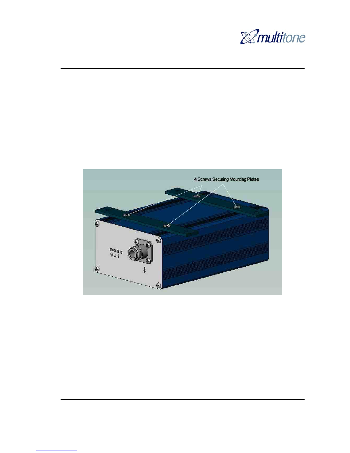
4.1 FITTING
The RPT500 can be wall or shelf mounted. For wall mounting there are two mounting brackets affixed
to the base of the transmitter. Attach the unit to the wall through the four mounting holes provided,
using suitable fixings.
For shelf mounting, remove the four screws affixing the wall mounting brackets and substitute the four
rubber feet supplied. Where this method of installation is used, ensure that the unit is physically stable
once all the leads have been connected.
An earth wire MUST be fitted to the 4mm earth screw terminal on the back of the transmitter, using the
earthing lead supplied, or suitable equivalent.
4.2 POWER SUPPLY
The power supply can be wall mounted, using the two holes in the mounting bracket supplied and
suitable fixings. Once the bracket is attached to the wall, fit the power supply to the bracket by feeding
the DC output lead through the square hole in the bracket, from the inside. With the power supply
sitting centrally between the two lugs of the bracket, insert the mains connector into the power supply
through the oval hole, ensuring that it is fully pushed in. This locks the power supply into the bracket.
 Loading...