

Multitone RPR 563, RPR 563K Amendment Instruction

Page 1
AMENDMENT INSTRUCTION NO. 236
AL2 TO TM1195 ISSUE 1
RPR 563/RPR 563K PAGING TRANSCEIVER
APRIL 1999
The attached amendment should be incorporated in the above Technical Manual
as soon as possible.
In line with the company policy of continued technical advancement, changes to
circuit diagrams and component layout diagrams are continually taking place. It is
not company policy that the technical manual should cover all previous issues of
products but only the latest design state. To this end, where an amendment
changes either the circuit diagram or component layout diagram, it may be prudent
to archive the previous diagrams, particularly if your product is of old design.
AFFECTED
PAGES
CHANGE
(iii)/(iv) AL2 amendments recorded.
1-7/1-8 New Rx frequency band and crystal information.
3-3/3-4 To add crystal frequency calculation for Band V.
3-7/3-8 Corrections to paragraphs 27 and 30.
5C-1/5C-2 Correction to part number for Test Probe.
6-1/6-2 Contents List updated. Addition of new frequency band.
6-3/6-4 Change to antenna information.
6-5/6-6 Component Change C306 (Band T).
6-7/6-8 Filter and inductor information for Band V.
6-9/6-10 Correction to part number for 560n inductor.
6-11/6-12 Adds R351 for Band V.
6-15/6-16 Para 24: Alternative part number for Gate Array.
Para 26: Adds Parts List for new Decoder PCB.
6-17/6-18 New pages with Parts List for new Decoder PCB.
7-1/7-2 Contents List updated.

AL2 to TM1195 Amendment Instruction No. 236
AFFECTED
PAGES
CHANGE
With the compliments of Multitone Electronics plc
PCN Nos. 4681, 4841, 4899, 5140, 5193
TPF003-02 [10/98]
Page 2
7-3/7-4 Figure 1: Change to L6.
7-7/7-8 Figure 3: Changes to R350/R351.
7-29/7-30 Adds Figure 14 (Decoder Circuit Diagram Sheet 1 of 2)
7-31/7-32 Adds Figure 15 (Decoder Circuit Diagram Sheet 2 of 2)
7-33/7-34 Adds Figure 16 (Decoder Component Location Sheet 1 of 2)
7-35 Adds Figure 17 (Decoder Component Location Sheet 2 of 2)
RPR 563
TM1195 Issue 1 Page (i)
TECHNICAL MANUAL
for
RADIO PAGING TRANSCEIVER
MODELS RPR 563/RPR 563K
Printed and Published in England

RPR 563
TM1195 Issue 1Page (ii)
COMPANY LIABILITY
The information in this manual has been carefully compiled and checked for technical
accuracy. Multitone Electronics plc accept no liability for inaccuracies or errors. In line with
the company policy of technical advancement, the information within this document may be
changed. The user should ensure that the correct issue of the document is used. Comments
or correspondence regarding this manual should be addressed to:
Multitone Electronics plc
Technical Publications
Kimbell Road
Basingstoke
Hampshire
RG22 4AD
England
ISSUE DATE
1 January 1997
© 1997 Multitone Electronics plc

RPR 563
TM1195 Issue 1 Page (iii)
CONTENTS
Page (i) Title Page
Page (ii) Company Liability
Page (iii) Contents
Page (iv) Effective Page List
Page (v) Safety Summary
Warning
Page (vi) Caution
Section 1 Introduction and Specification
Section 2 Operating Instructions
Section 3 Technical Description
Section 4 Installation & Commissioning
Section 5 Servicing
Section 6 Spare Parts List
Section 7 Diagrams

RPR 563
TM1195 Issue 1 AL2 (April 1999)Page (iv)
EFFECTIVE PAGE LIST
Page No. Issue Page No. Issue Page No. Issue Page No. Issue
(I) 1 2A-3 1 5-17 1 6-9 1 AL2
(ii) 1 2A-4 1 5-18 1 6-10 1
(iii) 1 3-1 1 5-19 1 6-11 1 AL2
(iv) 1 AL2 3-2 1 5-20 1 6-12 1 AL1
(v) 1 3-3 1 5-21 1 6-13 1 AL1
(vi) 1 3-4 1 AL2 5-22 1 6-14 1
1-1 1 3-5 1 5-23 1 6-15 1 AL2
1-2 1 3-6 1 5-24 1 6-16 1 AL2
1-3 1 3-7 1 AL2 5-25 1 6-17 1 AL2
1-4 1 3-8 1 AL2 5-26 1 6-18 1 AL2
1-5 1 3-9 1 5-27 1 7-1 1 AL2
1-6 1 3-10 1 5-28 1 7-2 1 AL2
1-7 1 AL2 3-11 1 5-29 1 7-3/4 1 AL2
1-8 1 3-12 1 5-30 1 7-5/6 1
1-9 1 4-1 1 5A-1 1 7-7/8 1 AL2
1-10 1 4-2 1 5A-2 1 7-9/10 1
2-1 1 5-1 1 5B-1 1 7-11/12 1
2-2 1 5-2 1 5B-2 1 7-13/14 1
2-3 1 5-3 1 5C-1 1 7-15/16 1
2-4 1 5-4 1 5C-2 1 AL2 7-17/18 1
2-5 1 5-5 1 5D-1 1 7-19/20 1
2-6 1 5-6 1 5D-2 1 7-21/22 1
2-7 1 5-7 1 6-1 1 AL2 7-23/24 1
2-8 1 5-8 1 6-2 1 AL2 7-25/26 1 AL1
2-9 1 5-9 1 6-3 1 AL2 7-27 1
2-10 1 5-10 1 6-4 1
2-11 1 5-11 1 6-5 1 AL2 7-29/7-30 1 AL2
2-12 1 5-12 1 6-6 1 AL2 7-31/7-32 1 AL2
2-13 1 5-13 1 6-7 1 AL2 7-33/7-34 1 AL2
2-14 1 5-14 1 6-8 1 AL2 7-35 1 AL2
2A-1 1 5-15 1
2A-2 1 5-16 1
RPR 563
TM1195 Issue 1 Page (v)
THE TRANSCEIVER SHOULD NOT BE CARRIED INTO AREAS WHERE EXPLOSIVE
GASES MAY BE PRESENT.
SAFETY SUMMARY
The following information applies to both operating and servicing personnel. General
Warnings and Cautions will be found throughout the manual, where they apply, which refer
to the applicable part of this summary.
WARNING statements identify conditions or practices that could result in personal injury or
loss of life.
CAUTION statements identify conditions or practices that could result in equipment damage.
WARNING

RPR 563
TM1195 Issue 1Page (vi)
CAUTION
STATIC SENSITIVE DEVICES ARE USED WITHIN THIS EQUIPMENT. CARE MUST BE
USED TO ENSURE DAMAGE TO THESE DEVICES IS NOT CAUSED BY HIGH LEVELS
OF STATIC ELECTRICITY. SPARE BOARDS OR COMPONENTS SHOULD BE STORED
IN ANTI-STATIC PACKAGING WHEN NOT INSTALLED IN THE EQUIPMENT.
PROTECT THE TRANSCEIVER FROM LIQUIDS, STRONG MAGNETIC FIELDS AND
EXTREME TEMPERATURES. DO NOT LEAVE THE TRANSCEIVER EXPOSED TO
STRONG SUNLIGHT. AREAS SUCH AS WINDOW LEDGES ARE TO BE AVOIDED.

RPR 563
TM1195 Issue 1 Page 1 - 1
SECTION 1
INTRODUCTION AND SPECIFICATION
CONTENTS:
1. ROLE
STANDARD FEATURES
6. Liquid Crystal Display (LCD)
7. Acoustic and Visual Alerts
8. Message Storage
9. Message Length
10. Beep Code Alpha
11. Automatic Speech Switching
12. Battery Economy Circuit (BEC)
13. Display Direction Control
14. Engineering Mode
OPTIONAL FEATURES
15. Permanent On
16. Alert Duration
17. Escalating Alert (Escalert)
18. Extended Alert
19. Group Call
20. Call Comparator
21. Time-of-Day
22. Mute Mode
23. Program Volume Levels
24. Battery Low Indication
25. Display Direction at Switch-On
26. Speech Timeout
27. Address Digits Displayed
28. Test Mode
29. System Number
30. System Retry Interval
31. Switch-On and Rack Message

RPR 563
TM1195 Issue 1Page 1 - 2
CONTENTS (Continued)
SPECIFICATION
32. Receiver
33. Transmitter
34. Signalling Formats
35. Power Supplies
36. Controls, Indicators, Alerts
37. Physical Characteristics
TABLE Page
1. DTMF Frequency Pairs 1 - 9
2. Battery Life 1 - 9
))))))))))))))))
ROLE
1. The Multitone RPR 563K radio paging transceiver comprises a UHF receiver and VHF
transmitter, allowing paging and two-way speech facilities. The unit can receive
alphanumeric paging messages and make paging, speech and telephone calls. The
transceiver may be used in simplex or duplex (telephone) mode.
2. Paging and telephone calls are made via a DTMF keypad. A reduced keypad version
of the transceiver, designated the RPR563 (which does not have a DTMF keypad) is
available which is able to make limited telephone calls.
3. A choice of plug-in metal hydride battery packs are available to power the transceiver.
All battery packs may be trickle or fast-charged via contacts in the base. Another set
of contacts in the battery pack allow the transceiver to be programmed, and allow
absence registration when used with absence/charging racks on Multitone paging
systems.
4. Paging calls to the receiver are in Multitone Mk7 digital format which has a capacity of
up to 10,000 individual address codes. Visual alert is by flashing LED and eight audible
tone alert patterns (Beep Code) are available. Alphanumeric messages can be
displayed on a 14-character dot matrix Liquid Crystal Display (LCD).
5. The transceiver is housed in a Bayblend case which provides a lightweight but strong
construction. A pocket clip, holster and wrist strap lanyard are available as carrying
devices.

RPR 563
TM1195 Issue 1 Page 1 - 3
STANDARD FEATURES
Liquid Crystal Display (LCD)
6. The LCD provides a visual display of up to 14 alphanumeric characters (longer
messages are displayed in 14 character blocks). A backlight provides enhanced LCD
viewing under low light conditions.
Acoustic and Visual Alerts
7. A range of eight different audible tone alert codes (beep codes) are programmed as
standard. These alerts, when initiated, are accompanied by the illumination of an LED
to provide visual indication of a paging call. Speech calls are indicated by ringing
patterns which match the appropriate tone alert codes.
Message Storage
8. Up to five messages may be stored by the transceiver for review later. They are held
on a first in/first out basis.
Message Length
9. The maximum length of any received message is between 63 and 81 characters,
depending on whether beep code alpha and time stamp are in use.
Beep Code Alpha
10. Up to four beep codes may be reserved to trigger an associated alphanumeric
message; each message not exceeding 14 characters in length.
Automatic Speech Switching
11. Allows speech to follow automatically after an alert tone.
Battery Economy Circuit (BEC)
12. The radio channel is monitored periodically and when no activity is present the receiver
circuits are powered down, hence conserving energy and battery life.

RPR 563
TM1195 Issue 1Page 1 - 4
Display Direction Control
13. The direction of the display may be changed to suit the way in which the transceiver is
carried.
Engineering Mode
14. May be used for reviewing programmed options in the transceiver. This feature is
useful for when carrying out engineering work on the paging system.
OPTIONAL FEATURES
Permanent On
15. When a battery pack is fitted and the Permanent On option enabled, the transceiver
cannot be switched off.
Alert Duration
16. This is the duration of the alert tone at normal volume level. Options are 8s, 16s, 32s,
or continuous alert. This does not include the period of any `Silent' and/or `Quiet'
beep(s) that may be programmed. When a speech call is received, the programmed
option is overridden and the alert duration is reduced to 4s.
Escalating Alert (Escalert)
17. Defines the alert sequence, which is four seconds of silence (LED only), followed by
four seconds of Quiet beep, and the remainder of the alert as Full beep.
Extended Alert
18. Extended Alert is an additional alert sequence which acts as a reminder if the original
alert is not acknowledged. During Extended Alert, the LED flashes every two seconds,
and every two minutes two pips are emitted unless the transceiver is in Mute Mode.
Group Call
19. Group Call is an option which allows the pager to be operated as part of a group (or
team). If enabled, any call to the group will alert the user audibly. The Group size may
be none, 10 or 100 as required.

RPR 563
TM1195 Issue 1 Page 1 - 5
Call Comparator
20. Prevents the transceiver from reacting to an identical message received within a pre-
determined period. Options are none, 30s, 120s, 300s or disabled.
Time-of-Day
21. When enabled, displays the time in hh:mm format. The transceiver uses an internal
clock which is synchronised by time information from the last valid Mk7 paging call.
Mute Mode
22. When Mute Mode is enabled, tone alert is suppressed when calls are received.
However, if a mute override beep code is received (triple pip or continuous pips), mute
is ignored and the transceiver responds with audible and visual alerts.
Program Volume Levels
23. On RPR 563K transceivers, the volume levels for beep tone, ring tone, telephone
speech, pager speech and DTMF echo may be adjusted from the keypad.
Battery Low Indication
24. Visual and audible indication of low battery voltage indication are available as
programmable options.
Display Direction at Switch-On
25. Display direction may be changed for handheld or belt-worn operation. When the
transceiver is switched off, the current display direction is stored in EEPROM, unless
the battery is low. The default display direction is correct for handheld operation.
Speech Timeout
26. The speech timeout duration may be set for 10s, 30s, 300s, or continuous. The default
is 300s.
Address Digits Displayed
27. At switch-on, the number of address digits displayed is programmable between two and
five digits. The default is five digits.

RPR 563
TM1195 Issue 1Page 1 - 6
Test Mode
28. This is for engineering use only. This feature limits the beep duration to one second
and defeats the call comparator.
System Number
29. The System Number for the Mk7 Digital paging format may be set to 0, 1, 2, or 3. The
default system number is 1.
System Retry Interval
30. The System Retry Interval may be set to 30s, 45s, 60s or 90s. The default is 30s.
Switch-On and Rack Message
31. A Switch-On message of up to 14 characters may be programmed. A Rack Message
of up nine characters, which is displayed when the transceiver is inserted into an
absence rack, may also be programmed. The default Switch-On message is
"Multitone 560" and the default Rack message is "Absent".

RPR 563
TM1195 Issue 1 AL2 (April 1999) Page 1 - 7
SPECIFICATION
Receiver
32. The following parameters apply to the receiver section of the transceiver:
a) Frequency Range: 438 - 470MHz
b) Frequency Bands: 438.000 - 438.999MHz
Z:
439.500 - 444.999MHz
Y: 445.000 - 452.999MHz
X: 453.000 - 460.999MHz
W: 461.000 - 470.000MHz
V: 439.000 - 439.499MHz
c) Number of Channels: 1
d) Channel Spacing: 20kHz/25kHz
e) Intermediate Frequencies: 45MHz and 455kHz.
f) Crystal Frequencies:
1st oscillator (XL303) carrier frequency - 45MHz
(Bands Z, Y, X, W) 9
1st oscillator (XL303) carrier frequency + 45MHz
(Band V only) 9
2nd oscillator (XL302) 44.545MHz
g) Sensitivity (TEM Cell): -93dBm (-99dBm typical) TEM Cell
(6dB degradation allowed at extremes of
operating temperature range).
h) Sensitivity (On-Body): 50µV/m (25µV/m typical) 8-position
i) Adjacent Channel Selectivity: Better than 50dB (60dB typical)
j) Co-Channel Rejection -12dB (-5dB typical)
k) Spurious Response 45dB (55dB typical)
l) Intermodulation Response: 45dB (55dB typical) 2-signal method.

RPR 563
TM1195 Issue 1Page 1 - 8
Transmitter
33. The following parameters apply to the transmitter section of the transceiver:
a) Frequency Range: 138 - 174.100MHz
b) Frequency Bands: Z: 138.000 - 140.499MHz
Y: 140.500 - 142.999MHz
X: 143.000 - 146.999MHz
W: 147.000 - 150.999MHz
V: 151.000 - 154.999MHz
U: 155.000 - 158.999MHz
T: 159.000 - 162.999MHz
S: 163.000 - 166.999MHz
R: 167.000 - 170.999MHz
Q: 171.000 - 174.100MHz
c) Number of Channels: 1
d) Channel Spacing: 12.5kHz or 25kHz.
e) Crystal Frequency: carrier frequency (MHz)
6
f) Frequency Stability: ±5ppm.
g) Radiated Output Power: #20mW
h) Adjacent Channel Power: 0.2µW at ±20kHz.
i) Antenna: Ferrite Stub (standard).
Flexible Whip (optional).
j) Deviation: ±2.25kHz (12.5kHz channel spacing)
±4.5kHz (25kHz channel spacing).
k) Spurious Radiation: 0.25µW max (30-1000MHz)
1.0µW max (1.0-12.75GHz)

RPR 563
TM1195 Issue 1 Page 1 - 9
TONE FREQUENCY
PAIRING
HIGH FREQUENCY GROUP (Hz)
1209 1336 1477 1633
LOW
FREQUENCY
GROUP (Hz)
697 1 2 3 A
770 4 5 6 B
852 7 8 9 C
941 * 0 # D
Table 1: DTMF Frequency Pairs
BATTERY
PACK
STANDBY
(NO TRAFFIC AND
CONTINUOUS ON)
USEAGE
PROFILE MODEL
(Tx TIME)
P566 120 HOURS 1 HOUR IN
12 HOUR SHIFT
P565 240 HOURS 2 HOURS IN
12 HOUR SHIFT
Table 2: Battery Life
Signalling Formats
34. The transceiver signalling parameters are as follows:
a) Tone Squelch Frequencies: 88.5, 103.5, 114.8, 127.3, 141.3, 151.4,
167.9Hz
b) Paging Code Format: Multitone Mk7 digital format (Manchester
encoded).
c) DTMF Frequency Pairs: see Table 1.
Power Supplies
35. The following re-chargeable battery packs are available for powering the transceiver:
a) Battery Type:
(I) 600mAH Battery Pack P566: 3.6V (nominal) Metal Hydride.
(ii) 1200mAH Battery Pack P565: Metal Hydride re-chargeable pack
b) Battery Life (typical):

RPR 563
TM1195 Issue 1Page 1 - 10
Controls, Indicators, Alerts
36. The following controls, indicators and alerts are available:
a) Controls: Keypad (15 keys on RPR 563K, 3 keys on
RPR 563).
Press-to-Talk button.
On/Cancel button.
b) Indicators: 14 character (7 x 5 dot matrix) Liquid
Crystal Display (LCD) with icon. Viewing
area 33.1mm x 5.8mm.
Alert LED (red).
Transmit LED (green).
Keyboard backlight.
c) Audible Alert 78dB (82dB typical) SPL @ 30cm (full
volume).
Physical Characteristics
37. The following parameters apply to the physical characteristics of the transceiver:
a) Temperature Range: -10EC to +55EC (Operational)
(LCD performance may be degraded below
0EC and above +45EC).
-20EC to +70EC (Storage)
b) Environmental: Designed to meet IP52
c) Dimensions: Length: 159mm
Width: 58mm
Depth: 27mm
Dimensions include 600mAH battery pack,
but exclude antenna and pocket clip.
d) Weight: #269gm with 1200mAH Battery Pack
e) Case Material: Bayblend in Storm Grey.

RPR 563
TM1195 Issue 1 Page 2 - 1
SECTION 2
OPERATING INSTRUCTIONS
CONTENTS:
1. CONTROLS AND INDICATORS
OPERATION
5. Fitting the Battery Pack
7. Switching On
9. Quiescent Mode
10. Receiving a Non-Speech Call
17. Receiving a Paging Speech Call
21. Receiving a Speech Call (Telephone Style)
23. Loud Speech (Simplex)
25. New Status
26. Cancelling Alerts
27. Escalating Alert
29. Extended Alert
30. Memory Replay
34. Making a Call (Telephone-Style Operation)
38. Making a Call to a Telephone (RPR 563K only)
39. Making a Call to Another Mobile (RPR 563K only)
42. Making a Call to a Manual Control Unit (RPR 563K only)
43. Terminating a Call
46. Program Volume Modes
48. RECHARGING THE BATTERY PACK
51. ABSENCE RACK REGISTRATION AND CHARGING
TABLES: Page
1. Message Display Formats 2 - 7
2. Beep Code and Alert Patterns 2 - 10

RPR 563
TM1195 Issue 1Page 2 - 2
THE TRANSCEIVER SHOULD NOT BE CARRIED INTO AREAS WHERE
EXPLOSIVE GASES MAY BE PRESENT.
CAUTION
PROTECT THE TRANSCEIVER FROM LIQUIDS, STRONG MAGNETIC FIELDS
AND EXTREME TEMPERATURES. DO NOT LEAVE THE TRANSCEIVER
EXPOSED TO STRONG SUNLIGHT. AREAS SUCH AS WINDOW LEDGES ARE
TO BE AVOIDED.
CONTENTS (Continued)
FIGURES: Page
1. Transceiver 2 - 3
2. DTMF Keypad and Function Keys 2 - 4
3. Fitting the Battery Pack 2 - 5
4. Switch On Sequence 2 - 6
ANNEXE:
A Engineering Mode
WARNING
1
3
4
5
6
7
8
9
10
12
11
13
14
2
TAG10665-2
RPR 563
TM1195 Issue 1 Page 2 - 3
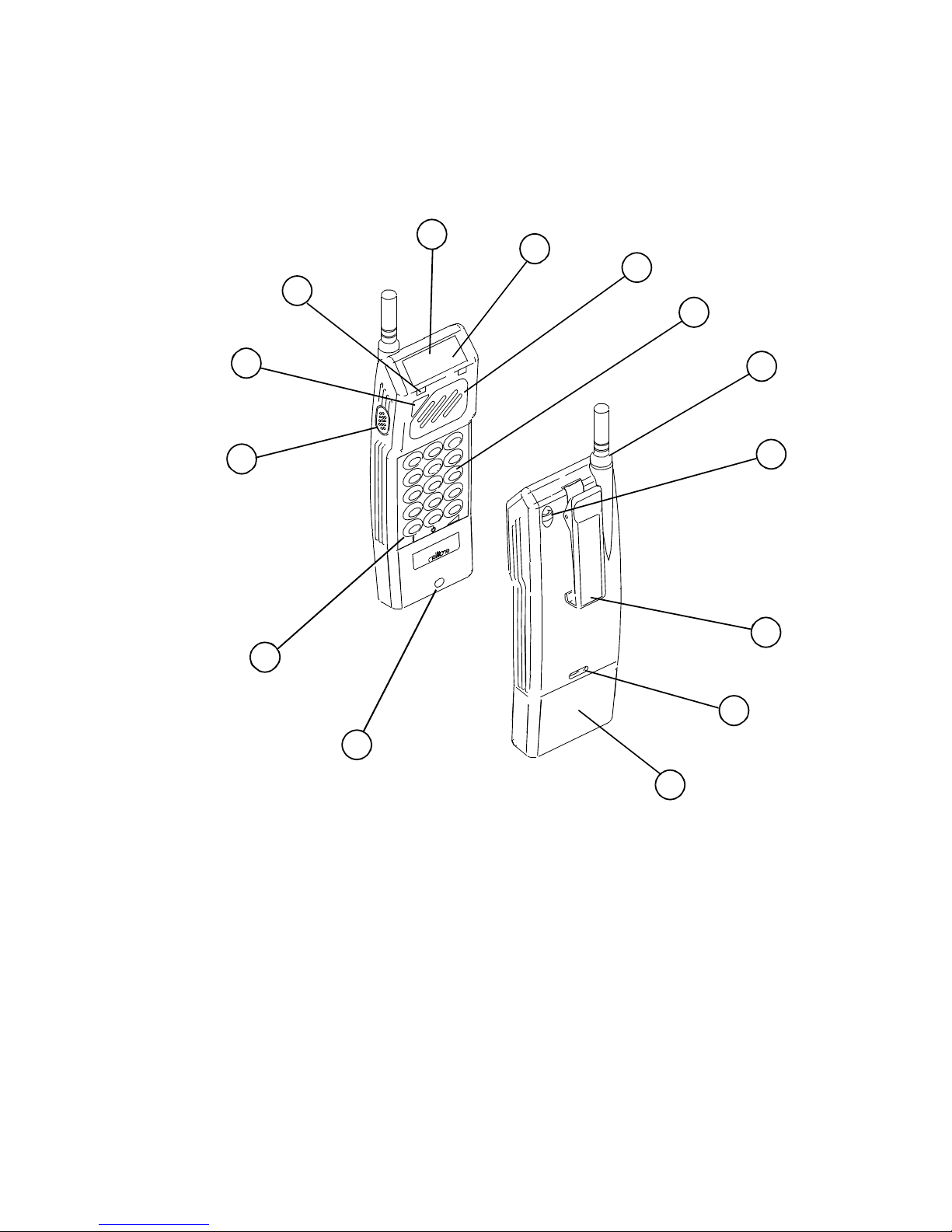
KEY:
1. Microphone
2. Function Keys
3. Press-to-Talk Button
4. Cancel/On/Memory Button
5. Alert LED
6. Liquid Crystal Display
7. Tx LED
8. Loudspeaker
9. DTMF Keypad (RPR563K only)
10. Antenna
11. Wrist Strap Loop
12. Pocket Clip
13. Battery Pack Button
14. Battery Pack
Figure 1: Transceiver
CONTROLS AND INDICATORS
1. Controls and indicators for the transceiver are shown in Figure 2.

DTMF KEYPAD
(`K' VERSIONS ONLY)
FUNCTION KEYS
TAG10666-1
RPR 563
TM1195 Issue 1Page 2 - 4
Figure 2: DTMF Keypad and Function Keys
2. The following controls are found on both the full and reduced keypad versions of the
transceiver:
PRESS-TO-TALK Used to manually key the transmitter on (paging calls only).
ON/CANCEL/ Initially switches on the transceiver and then subsequently
MEMORY cancels incoming calls, or illuminates LCD and keypad (when
RECALL no calls received). Recalls stored messages.
LINE Press button to request a line before dialling telephone or
paging code (or for direct connection on reduced keypad
option). Pressing the button during a telephone call puts the
transceiver into loud speech mode. Press the Shift key
followed by for Emergency line request.
CLEAR/OFF/ Pressing during a speech call ends the call. Press the
MUTE Shift key ( ) followed by to mute the transceiver.
Press Shift and hold down for three seconds to
switch off transceiver.
SHIFT/REVERSE Press and hold to adjust speech volume ( ) during a call.
Used in conjunction with a second key initiates the alternative
function for that key. Pressed twice during status
interrogation reverses display.
3. In addition to the controls in paragraph 2, the full keypad version also has keys `0' to
`9', `*' and `#'.
TAG10152-2
RPR 563
TM1195 Issue 1 Page 2 - 5
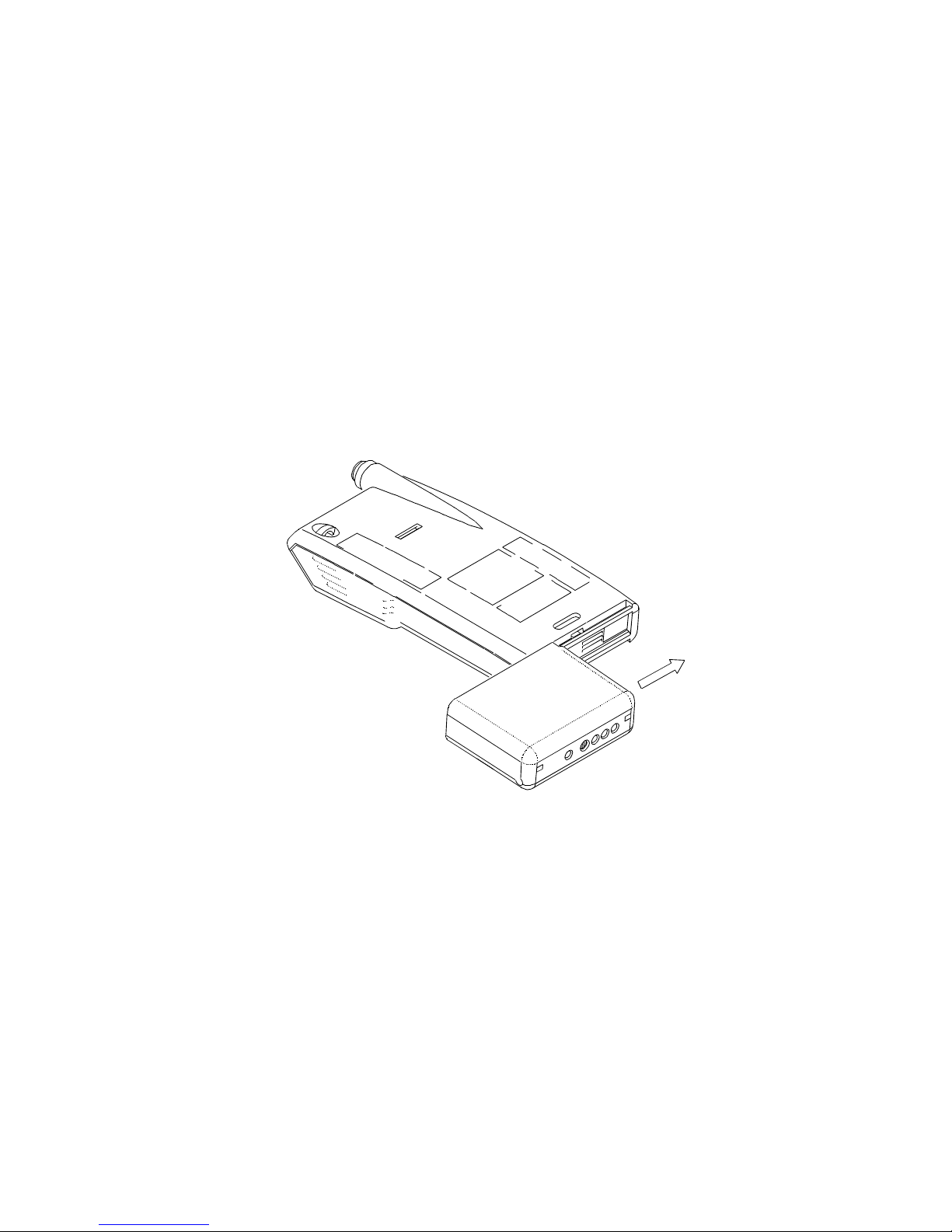
Figure 3: Fitting the Battery Pack
4. The transceiver has the following indicators:
a) LCD A 14-character alphanumeric display. This displays paging call
messages, and transceiver and system status messages.
b) Tx KEY Lights when the transmitter is active.
c) ALERT Lights when a paging call has been received.
OPERATION
Fitting the Battery Pack
5. Refer to Figure 3. Hold the battery against the transceiver as shown in Figure 3. Slide
the battery pack onto the lower edge of the transceiver until it clicks into position.
6. Removal is a reversal of the above procedure, but press the battery button before
releasing the battery pack.
QUIET TONE (2.73kHz) *
ALERT LAMP
SHOW ALL LCD SEGMENTS
RECEIVER ADDRESS
SWITCH-ON MESSAGE
BACKLIGHTS
1 2 3 4 5 6 7 8
SECONDS
* QUIET TONE IS MODULATED IF BATTERY VOLTAGE IS LOW.
TAG10151-2
RPR 563
TM1195 Issue 1Page 2 - 6
Figure 4: Switch On Sequence
Switching On
7. Check that a fully-charged battery pack has been fitted. Press once. The
transceiver will initiate its switch on sequence as shown in Figure 4.
8. The address display will depend on the number of address digits option. When the
switch-on sequence has finished the transceiver enters the quiescent mode. If the
EEPROM is faulty, then a series of `E's will be displayed.
Quiescent Mode
9. This is the transceiver's normal operating state, when no calls are being made or being
received, no buttons are pressed and the backlights are off. The display shows the
highest priority status, and, if enabled, Time-of-Day information (hh:mm) derived from
the transceiver's internal clock.
Receiving a Non-Speech Call
10. When a call is received, the Alert LED will flash and, optionally, an audible alert tone
will be generated. The alert tone will follow one of eight tone patterns which are
summarised in Table 2. Press to cancel the alert and read the accompanying
message.
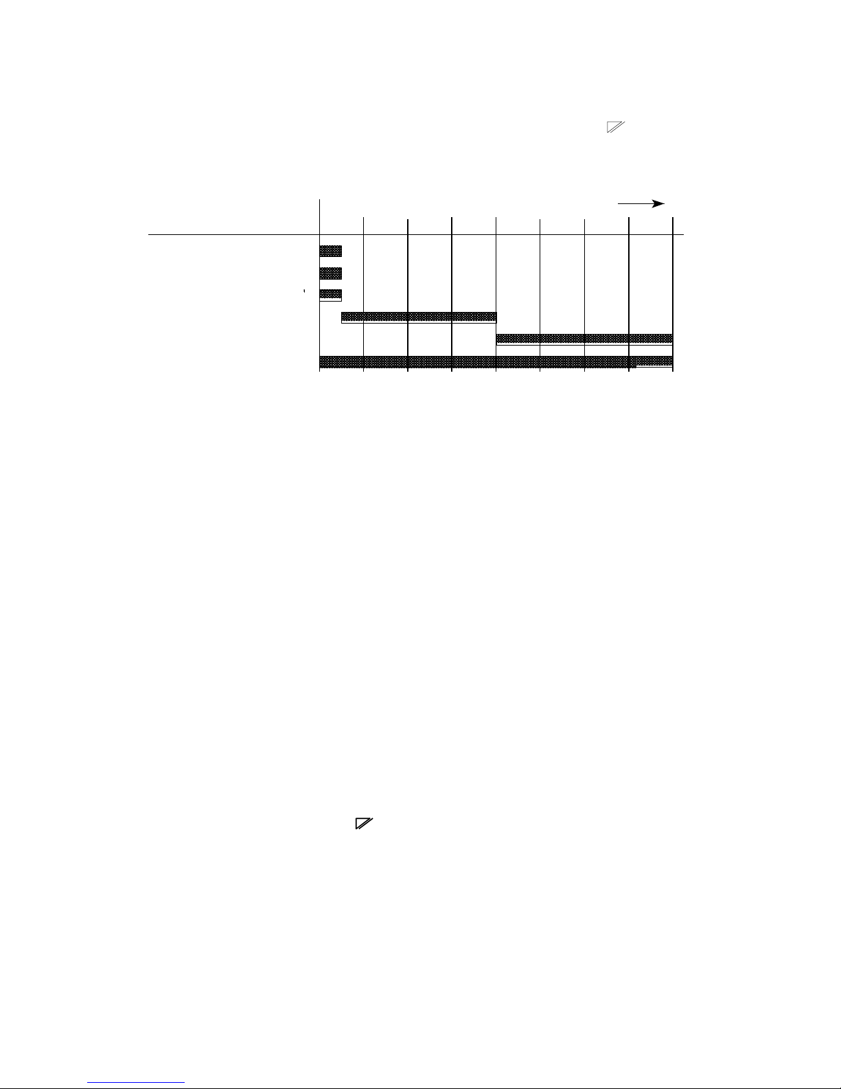
TONE ONLY, NO MESSAGE, NO SPEECH
CALL TYPE
SPEECH ONLY
BEEP CODE ALPHA, NO OFF-AIR
MESSAGE (WITH OR WITHOUT SPEECH)
OFF-AIR MESSAGE AND BEEP CODE
ALPHA (WITH OR WITHOUT SPEECH)
12:00 4 **
12:01 Call Ended **
12:02 Fire **
12:03 Go to Room 26 **
T
T T
T
T
T
T T
T T
T T T
EXAMPLE
RPR 563
TM1195 Issue 1 Page 2 - 7
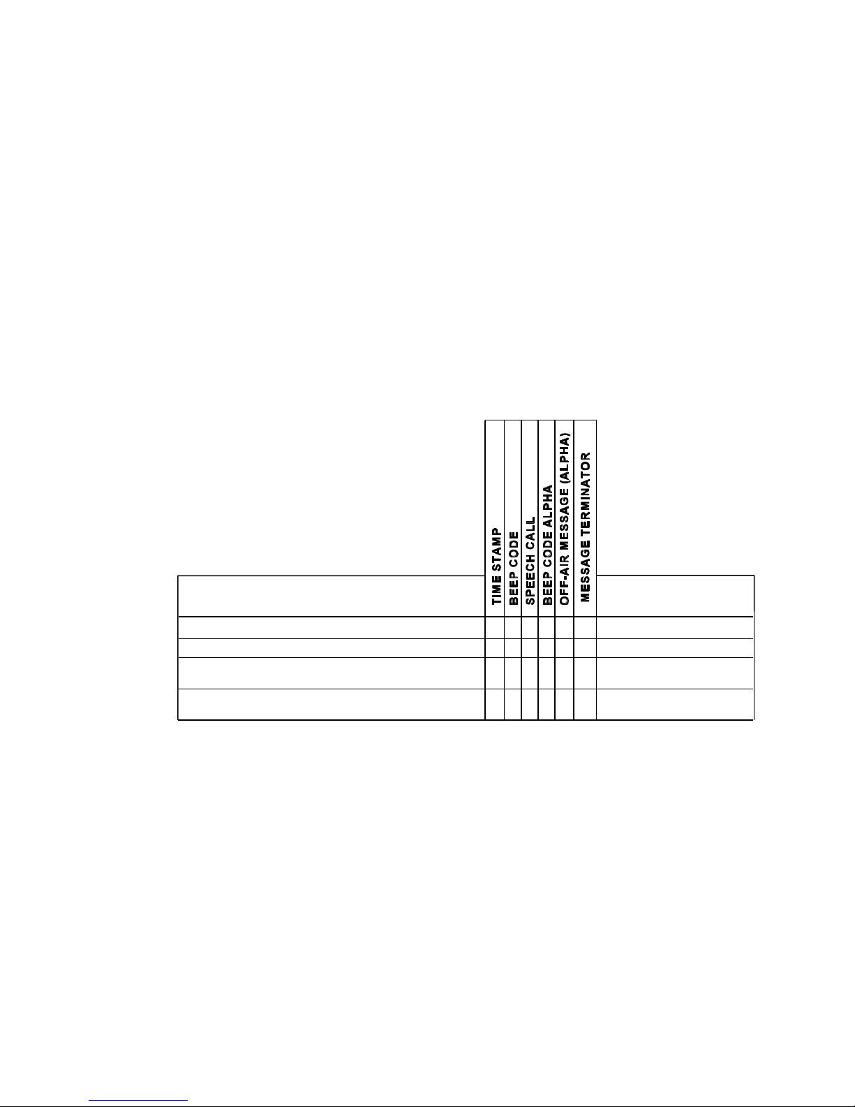
Table 1: Message Display Formats
11. The displayed message comprises combinations of the following elements:
Element Example
a) Time stamp + space 12:00
b) Beep Code (Tone Only message) 4
c) Speech call Speech
d) Beep code alpha Fire
e) Off-Air Message (Alpha) Please call reception
f) Message Terminator ** or **?
12. Unless in test mode, all messages are in one of the formats shown in Table 1.
13. The terminator **? is used when the call contains any suspect characters, or is
terminated early because of corrupt data. Otherwise the terminator ** is used.
14. When the total message length is 14 characters or less, it is displayed for the duration
of the alert, if uncancelled. On cancelling the alert the message is displayed for a
further 2.5 seconds.
15. When the total message length is greater than 14 characters, it scrolls through to the
end of the message at 1.25 second intervals, pausing for 2.5 seconds on the final
screen. This process continues until the alert is cancelled. On cancelling the alert the
message is displayed again from the beginning.

RPR 563
TM1195 Issue 1Page 2 - 8
16. The transceiver is able to receive new calls during an alert, although receiver sensitivity
may be degraded. The new call takes over the previous call, which is placed in
memory. Preceding calls have "new" status unless cancelled during the alert.
Receiving a Paging Speech Call
17. When a call is received, the Alert LED will flash and a telephone-style ringing tone will
be audible for four seconds. Any alphanumeric message will be displayed as for a nonspeech call. The speech audio channel switches on immediately after the audible alert.
18. Press to cancel the alert and wait to hear the speech message. A further press of
the button cancels speech. If is pressed again, before the speech timeout period
expires, the speech channel may be re-opened.
19. The call is terminated by one of the following actions:
a) pressing
b) pressing
c) expiration of the transceiver speech timeout
d) a Mk7 speech termination signal from the paging system.
20. If the speech call has been rejected by two presses of , any subsequent pressing of
is assumed to be a new call request (see `Making a Call').
Receiving a Speech Call (Telephone Style)
21. Assuming a speech call has been received (as in paragraph 17) press to talk back.
The transceiver will be switched into telephone mode and the speech audio level will
drop to the programmed telephone speech level. The display direction will be set to
read correctly for keyboard use. When the call ends, volume level and display direction
will return to their default settings. Extended alert and new status are cancelled.
22. The call is terminated by pressing , the speech timeout, or by a Mk7 speech
termination signal from the paging system. The transceiver will display the message
"Call Ended".

RPR 563
TM1195 Issue 1 Page 2 - 9
Loud Speech (Simplex)
23. Under some circumstances telephone-style communication will not be possible,
e.g. noisy environment, wearing of protective headgear. The high volume levels
required for listening would inhibit operation because of feedback. In this situation a
PMR-style of operation is desirable.
24. To select loud speech, press twice (the message "Use PTT" is displayed). To
speak, depress the PTT key. Release the PTT switch after speaking, to listen to the
other party. Subsequent presses of toggles the transceiver between telephone
mode (the message "On" is displayed) and loud speech mode (message "Use PTT" is
displayed).
New Status
25. Each call is automatically given new status when first received. New status is removed
by cancelling the alert or reviewing the call from memory. If the alert is left uncancelled
then the prompt "x new messages" appears on the display showing the number of
messages with new status (where x is a integer from 1 to 5). Each message must be
viewed in full for new status to be removed.
Cancelling Alerts
26. Cancel the alert by pressing the button. The beep and LED alert cease but the
message is replayed from the beginning.
Escalating Alert
27. The escalating alert has three stages - the first two lasting 4 seconds each and the last
one 8s, 16s, 32s or continuous. The stages are as follows:
Stage 1: LED, flashing beep pattern.
Stage 2: LED, low volume beep pattern.
Stage 3: LED, full volume beep pattern.
28. The option for Escalating Alert is programmed into the EEPROM. However, the
escalating alert and the Mute mode are overridden by beep code 5 (triple pip) and beep
code 8 (continuous pip). They cause the alert to be on full volume for the whole of the
programmed alert duration.
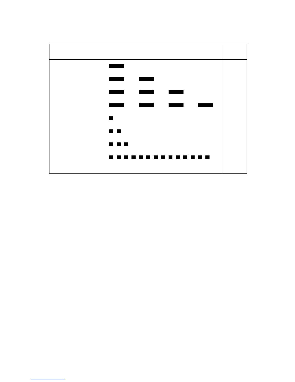
CONTINUOUS BEEP
SINGLE BEEP
DOUBLE BEEP
TRIPLE BEEP
SINGLE PIP
DOUBLE PIP
TRIPLE PIP
CONTINUOUS PIP
SILENT ALERT
PIP/BEEP TONE ALERT PATTERN
4
1
3
2
6
7
5*
8*
9
BEEP
CODE
RPR 563
TM1195 Issue 1Page 2 - 10
Table 2: Beep Code and Alert Patterns
* The escalating alert and the Mute mode are overridden by beep code 5
(triple pip) and beep code 8 (continuous pip). They cause the alert to be on
full volume for the whole of the programmed alert time, or for four seconds
if it is a speech call.
NOTE: Silent Alert is not currently supported by Access 3000 systems.
Extended Alert
29. If enabled and the call is not cancelled, the transceiver enters extended alert after the
normal alert has finished. During extended alert, the LED flashes for 0.125s, every 2s.
Two 0.125s pips (2s apart) are emitted every two minutes (unless in Mute mode). The
pips are synchronised to the LED flashes.

RPR 563
TM1195 Issue 1 Page 2 - 11
Memory Replay
30. Incoming messages are automatically entered into the transceiver's memory store which
can accommodate up to five calls. To start the memory replay cycle, from the quiescent
display, press the button twice. If in extended alert, press the key once only.
The transceiver displays the header of the first message (or the phrase "no messages"
if none exist). If no messages exist, the display returns to quiescent mode after
2 seconds.
31. New messages which have not been cancelled are displayed first. When all new
messages have been reviewed, the transceiver returns to quiescent mode. Once new
status has been removed it is possible to view all the messages in the memory by
pressing again.
32. The header refers to the first message screen and consists of a time stamp, plus the
initial part of the message (or the whole message if 14 characters or less). Press
to step through each message header on the display. The most recent call is displayed
first and corresponds to the `1'.
33. The display automatically scrolls through messages at 1.25 second intervals until the
final screen is reached. The final screen terminates in ** (to denote the end of the
message) and is displayed for 2.5 seconds. If all messages have been viewed the
transceiver display returns to the quiescent condition.
Making a Call (Telephone-Style Operation)
34. The procedure for making a telephone-style call is as follows:
a) Press . The message "Please Wait" will be displayed. If the channel is clear
(i.e. the base station is not transmitting) then the transceiver sends its Talk code
in DTMF. The transceiver then reverts to its quiescent state.
b) When the paging system is ready to service the call it sends a "Line Ready" call.
The transceiver rings, displays the message "Ready" and drops into telephone
mode, i.e. the transceiver audio volume will be adjusted to telephone speech level.
Dial tones from the paging system will normally be heard from the transceiver.
c) Enter the required dialling sequence.
35. If, after a predetermined interval, the paging system does not respond with a "Line
Ready" call, the transceiver sends its Talk code again, and repeats this process at the
specified interval until a response is received from the paging system. If the key
has been pressed and a Line Ready call is subsequently received, the transceiver still
sends the Un-Talk code and reverts to its quiescent state.
36. The line request can be cancelled at any time by pressing .

RPR 563
TM1195 Issue 1Page 2 - 12
37. On reduced keypad versions, connection to the designated point is automatic once
has been pressed.
Making a Call to a Telephone (RPR 563K only)
38. Once the dialling tone has been received, the telephone number may be dialled as if
calling from another telephone.
Making a Call to Another Mobile (RPR 563K only)
39. The procedure for making a call to another mobile is as detailed in paragraph 34. If the
call is to another paging receiver, then the user number and numeric message must be
dialled when requested by the paging system.
40. A control message is sent by the paging system which sets the transceiver into simplex
mode. The message "Use PTT" is displayed by the transceiver.
41. If the recipient is a non-speech paging receiver then the paging system clears down the
originator when the message has been sent.
Making a Call to a Manual Control Unit (RPR 563K only)
42. Once the "Line Ready" call has been received, connection is made using designated
MCU intercepts. The default intercept numbers are:
*0 to call several MCUs which have continuous talkback monitoring facilities
or:
*1 to *8 to call a designated MCU.
Terminating a Call
43. To terminate a call, press . The transceiver sends its Un-Talk code, displays the
message "Call Ended" and reverts to quiescent state.
44. An internal speech timeout function will terminate a speech call if it has not been
terminated manually. The paging system may also terminate the call but will warn the
user with a tone a few seconds before termination.
 Loading...