

Multitone RPR 551IS, RPR 553IS, RPR 552IS Technical Manual

Page 1
AMENDMENT INSTRUCTION NO. 234a
AL2 TO TM1188 ISSUE 1
RPR 550IS SERIES PAGING RECEIVERS
OCTOBER 1998
PLEASE NOTE THAT THIS AMENDMENT INSTRUCTION (No. 234a) REPLACES
INSTRUCTION No. 234 WHICH HAD A PAGE ERROR. PLEASE DESTROY ANY
COPIES OF INSTRUCTION 234 YOU MAY HAVE RECEIVED AND USE THE
PAGES SUPPLIED WITH THIS INSTRUCTION SHEET INSTEAD.
The attached amendment should be incorporated in the above Technical Manual
as soon as possible.
In line with the company policy of continued technical advancement, changes to
circuit diagrams and component layout diagrams are continually taking place. It is
not company policy that the technical manual should cover all previous issues of
products but only the latest design state. To this end, where an amendment
changes either the circuit diagram or component layout diagram, it may be prudent
to archive the previous diagrams, particularly if your product is of old design.
AFFECTED
PAGES
CHANGE
(i)/(ii) Change to address.
(iii)/(iv) AL2 amendments recorded.
(v)/(vi) AL2 amendments recorded. Warnings updated.
(vii)/(viii) Ambiguity in Caution removed. Updates to FCC compliance
statement.
1-1/1-2 Contents List updated.
1-5/1-6 Para 9. New Table added to sub-para b). Sub-paragraphs c)
and d) removed.
1-9/1-10 Existing Table 4 now re-numbered Table 5.
2-13/2-14 Change to wording of Warning.
5-31/5-32 Para 24: Warning added.

AL2 to TM1188 Amendment Instruction No. 234
AFFECTED
PAGES
CHANGE
With the compliments of Multitone Electronics plc
PCN Nos. 4883, 4899, 5031, 5183
TPF003-01 [August 1996]
Page 2
6-5/6-6 Component change: D9, 13, 15, 16, 17, 18.
6-7/6-8 Component change: R72
7-1/7-2 Contents List updated.
7-9/7-10 Drawing now at Issue 2.
7-21/7-22 Drawing now at Issue 4.
7-23/7-24 Drawing now at Issue 4.
RPR 550IS Series
TM1188 Issue 1 AL2 (Oct. 98) Page (i)
TECHNICAL MANUAL
for
RADIO PAGING RECEIVERS
MODELS RPR 551IS, RPR 552IS AND RPR 553IS
Printed and published in England

RPR 550IS Series
TM1188 Issue 1 AL2 (Oct. 98)Page (ii)
COMPANY LIABILITY
The information in this manual has been carefully compiled and checked for technical
accuracy. Multitone Electronics plc accept no liability for inaccuracies or errors. In line with
the company policy of technical advancement, the information within this document may be
changed. The user should ensure that the correct issue of the document is used. Comments
or correspondence regarding this manual should be addressed to:
Multitone Electronics plc
Technical Publications
Kimbell Road
Basingstoke
Hampshire
RG22 4AD
England
ISSUE DATE
1 February 1995
© Multitone Electronics plc 1995

RPR 550IS Series
TM1188 Issue 1 AL2 (Oct. 98) Page (iii)
CONTENTS
Page (i) Title Page
Page (ii) Company Liability
Page (iii) Contents
Page (iv) (v) Effective Page List
Page (vi) Safety Summary
Warnings
Page (vii) Cautions
FCC Part 15 Compliance
Section 1 Introduction and Specification
Section 2 Operating Instructions
Section 3 Technical Description
Section 4 Installation and Commissioning
Section 5 Servicing
Section 6 Spare Parts List
Section 7 Diagrams

RPR 550IS Series
TM1188 Issue 1 AL2 (Oct. 98)Page (iv)
EFFECTIVE PAGE LIST
Page No. Issue Page No. Issue Page No. Issue Page No. Issue
(i) 1 2-11 1 3A-1 1 5-17 1
(ii) 1 AL2 2-12 1 3A-2 1 5-18 1
(iii) 1 2-13 1 3A-3 1 5-19 1
(iv) 1 AL2 2-14 1 3A-4 1 5-20 1
(v) 1 AL2 2-15 1 3A-5 1 5-21 1
(vi) 1 AL2 2-16 1 3A-6 1 5-22 1
(vii) 1 AL2 2A-1 1 3A-7 1 5-23 1
(viii) 1 2A-2 1 3A-8 1 5-24 1
1-1 1 AL2 2A-3 1 3A-9 1 5-25 1
1-2 1 AL2 2A-4 1 3A-10 1 5-26 1
1-3 1 2A-5 1 4-1 1 5-27 1
1-4 1 2A-6 1 4-2 1 5-28 1
1-5 1 3-1 1 5-1 1 5-29 1
1-6 1 AL2 3-2 1 5-2 1 5-30 1
1-7 1 3-3 1 5-3 1 5-31 1
1-8 1 3-4 1 5-4 1 5-32 1
1-9 1 AL2 3-5 1 5-5 1 5-33 1
1-10 1 3-6 1 5-6 1 5-34 1
2-1 1 3-7 1 5-7 1 5-35 1
2-2 1 3-8 1 5-8 1 5-36 1
2-3 1 3-9 1 5-9 1 5-37 1
2-4 1 3-10 1 5-10 1 5-38 1
2-5 1 3-11 1 5-11 1 5A-1 1
2-6 1 3-12 1 5-12 1 5A-2 1
2-7 1 3-13 1 5-13 1 5B-1 1
2-8 1 3-14 1 5-14 1 5B-2 1
2-9 1 3-15 1 5-15 1 6-1 1 AL1
2-10 1 3-16 1 5-16 1 6-2 1 AL1

RPR 550IS Series
TM1188 Issue 1 AL2 (Oct. 98) Page (v)
EFFECTIVE PAGE LIST (Continued)
Page Issue Page No. Issue Page No. Issue Page No. Issue
6-3 1 AL1 7-1 1 AL2 7-13 1 7-27 1
6-4 1 AL1 7-2 1 AL2 7-14 1 7-28 1 AL1
6-5 1 AL1 7-3/4 1 7-15/161 7-29/301
6-6 1 AL2 7-31/321
6-7 1 AL2 7-6 1 7-18 1 7-33 1
6-8 1 AL1
6-9 1 AL1 7-8 1 7-20 1
6-10 1 AL1
6-11 1 AL1 7-23/241 AL2
6-12 1 AL1 7-11 1
6-13 1 AL1
6-14 1 AL1
7-5 1 7-17 1
7-7 1 7-19 1
7-9/10 1 AL2 7-21/221 AL2
7-12 1 7-25/261

RPR 550IS Series
TM1188 Issue 1 AL2 (Oct. 98)Page (vi)
ANY COMPONENT MARKED THUS i ON CIRCUIT DIAGRAMS MAY ONLY BE
REPLACED BY ANOTHER OF AN IDENTICAL TYPE AND SPECIFICATION. THE
LEAD LENGTH AND LOCATION MUST BE IDENTICAL TO THAT OF THE
ORIGINAL COMPONENT.
THE FOLLOWING PRECAUTIONS MUST BE OBSERVED WHEN CHARGING OR
REPLACING THE BATTERY.
SAFETY SUMMARY
The following information applies to both operating and servicing personnel. General
Warnings and Cautions will be found throughout the manual where they apply.
WARNING statements identify conditions or practices that could result in injury or loss of life.
CAUTION statements identify conditions or practices that could result in equipment damage.
WARNINGS
1. DO NOT attempt to replace or charge a battery in a hazardous area
where explosive gases may be present.
2. Only the battery types listed on the equipment label and in the User
Guide may be used with RPR 550IS series pagers.
3. Only Absence and Charging Racks A3RO and A3RP are to be used
with RPR 550IS pagers. When Charging is enabled on these racks,
only pagers with rechargeable batteries should be inserted into the
Charging Rack pockets.
4. Always ensure that the battery door is secured before use.

RPR 550IS Series
TM1188 Issue 1 AL2 (Oct. 98) Page (vii)
CAUTIONS
PROTECT THE PAGER FROM LIQUIDS, STRONG MAGNETIC FIELDS AND EXTREME
TEMPERATURES. DO NOT LEAVE THE PAGER EXPOSED TO STRONG SUNLIGHT.
AVOID SUCH AREAS AS CAR INTERIORS AND WINDOW LEDGES.
STATIC SENSITIVE DEVICES ARE USED WITHIN THIS EQUIPMENT. CARE MUST BE
TAKEN TO ENSURE DAMAGE TO THESE DEVICES IS NOT CAUSED BY HIGH LEVELS
OF STATIC ELECTRICITY.
DO NOT PRESS THE OFF BUTTON WHEN THE PAGER IS IN THE ABSENCE RACK OR
PROGRAMMING POCKET AS THIS MAY CORRUPT THE EEPROM.
FCC PART 15 COMPLIANCE
This device complies with Part 15 of the FCC Rules. Operation is subject to the condition that
this device does not cause harmful interference.
Any unauthorised modification to this device may void the user's authority to operate the
equipment.
Important Intrinsic Safety Information
THIS RADIO PAGING RECEIVER HAS BEEN CERTIFIED TO EUROPEAN HARMONISED
SPECIFICATIONS FOR INTRINSIC SAFETY, EN50 014 (1977) + AMENDMENTS 1-5 AND
EN50 020 (1977) + AMENDMENTS 1-2.
CLASSIFICATION HAS BEEN GRANTED TO EEx ia IIC T5 OR T6 (AMBIENT
TEMPERATURE DEPENDENT) AND EEx ia IIC T4. THE TEMPERATURE (T)
CLASSIFICATIONS ARE DEPENDENT UPON THE BATTERY TYPE USED AND
TEMPERATURE CLASSIFICATION INFORMATION, GIVEN ON THE LABELLING OF EACH
INDIVIDUAL RECEIVER.
MAINTENANCE AND REPAIRS TO THIS EQUIPMENT MAY ONLY BE CARRIED OUT BY
MULTITONE AUTHORISED PERSONNEL. LIABILITY IS NOT ACCEPTED FOR WORK
CARRIED OUT BY OTHER THIRD PARTIES.
EQUIPMENT MUST ONLY BE CONNECTED TO MULTITONE SPECIFIED CHARGING AND
DATA FACILITIES.
EQUIPMENT PROGRAMMING MUST ONLY BE CARRIED OUT BY MULTITONE
AUTHORISED PERSONNEL, USING THE RECOMMENDED APPARATUS.

RPR 550IS Series
TM1188 Issue 1 AL2 (Oct. 98)Page (viii)
INTENTIONALLY BLANK

RPR 550IS Series
TM1188 Issue 1 AL2 (Oct. 98) Page 1 - 1
SECTION 1
INTRODUCTION AND SPECIFICATION
CONTENTS:
1. INTRODUCTION
3. STANDARD FEATURES
4. OPTIONAL FEATURES
SPECIFICATIONS
5. RPR 551IS Receiver Performance
6. RPR 552IS Receiver Performance
7. RPR 553IS Receiver Performance
9 Power Supply
10. Code Format
11. Display, Controls and Alerts
12. Memory
13. Beep Code Alpha
14. Operational Environment
15. Dimensions
16. Weight
TABLES Page
1. RPR 551IS Sensitivity Figures 1-3
2. RPR 552IS Sensitivity Figures 1-4
3. RPR 553IS Sensitivity Figures 1-5
4. Battery Life 1-6
5. Typical Pager Weights 1-9

RPR 550IS Series
TM1188 Issue 1 AL2 (Oct. 98)Page 1 - 2
INTRODUCTION
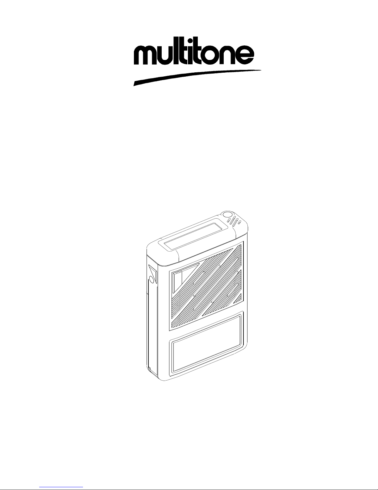
1. The Radio Paging Receiver (RPR) 550 Intrinsically Safe (IS) Series consists of RPR
551IS, RPR 552IS and RPR 553IS pagers. They are small, well constructed, easy to
operate and respond to Multitone Mk7 radio paging transmissions in the HF, VHF and
UHF bands respectively.
2. The user is alerted to a paging call by beep tones, flashing LED and optionally speech
or vibration. Pagers can be programmed to be called individually or as part of a group.
STANDARD FEATURES
3. The following operating facilities and features are provided:
! Call capacity of up to 40,000 individual address codes (10,000 per system number)
! Choice of languages for display indications
! Eight different audible tone alert patterns (beep codes) plus one silent alert
! Alert LED
! Automatic speech switching - speech automatically follows alert tones
! A fourteen character dot matrix Liquid Crystal Display (LCD)
! Alphanumeric display capability
! Memory recall facility storing up to five messages
! Display direction control - normal or reverse orientation
! Charging/absence/programming contacts
! Battery economy circuit
! Bayblend case
! Detachable Griptite clip
OPTIONAL FEATURES
4. The following optional features can be selected:
! Permanent On
! Mute mode - when silent alert required
! Vibrate alert
! Escalating alert
! Alert duration
! Extended alert
! Continuous display

RPR 550IS Series
TM1188 Issue 1 Page 1 - 3
! Group alert call (group of up to 10 or 100)
! Call comparator - inhibits pager from responding to two identical calls within
predetermined time limit when used with a suitable encoder e.g. Access 3000
! Time-of-Day display
! Message time stamp
! Out-of-Range warning
! Battery low indication (not recommended with rechargeable cells)
! Test mode - short alert (engineering use only)
! Detachable Lanyard
! Beep code alpha - pre-programmed messages related to four beep codes
SPECIFICATIONS
RPR 551IS Receiver Performance
5. The receiver performance is as follows:
a) Frequency Range: 25.0MHz to 54.000MHz
b) Frequency Bands: 1: 25.0MHz to 27.499MHz
2: 27.5MHz to 30.499MHz
3: 30.5MHz to 34.999MHz
4: 35.0MHz to 38.999MHz
5: 39.0MHz to 43.499MHz
6: 43.5MHz to 48.499MHz
7: 48.5MHz to 54.000MHz
c) Channel Spacing: 10/12.5kHz or 20/25kHz
d) Sensitivity:
Table 1: RPR 551IS Sensitivity Figures
MEASUREMENT
MODE
TYPICAL
BEST POSITION
8 POSITION
AVERAGE
On Body 15µVm 20µVm
-1 -1

RPR 550IS Series
TM1188 Issue 1Page 1 - 4
e) Adjacent Channel Selectivity: 65dB at 20/25kHz
55dB at 12.5kHz
45dB at 10kHz
f) Image Response: 15dB
g) Spurious Response: 50dB
h) Spurious Emissions to 1GHz:
#2nW
j) Intermodulation Response: 55dB
(2+4, 4+8 channel separation)
k) Co-channel rejection: -5dB
NOTE: The figures quoted in (d) to (k) are typical for the frequency range 25MHz to
54MHz and assume an ambient temperature in the range 18
EC to 25EC.
RPR 552IS Receiver Performance
6. The receiver performance is as follows:
a) Frequency Range: 138MHz to 174.999MHz
b) Frequency Bands: 1: 138MHz to 148.999MHz
2: 149MHz to 160.999MHz
3: 161MHz to 174.000MHz
c) Channel Spacing: 20/25kHz
d) Sensitivity:
Table 2: RPR 552IS Sensitivity Figures
MEASUREMENT
MODE
TYPICAL
BEST POSITION
8 POSITION
AVERAGE
On Body 14µVm 22µVm
-1 -1
e) Adjacent Channel Selectivity: 75dB at 20/25kHz
f) Image Response: 63dB
g) Spurious Response: 60dB
h) Spurious Emissions to 1GHz:
#2nW

RPR 550IS Series
TM1188 Issue 1 Page 1 - 5
j) Intermodulation Response: 60dB
(2+4, 4+8 channel separation)
k) Co-channel rejection: -5dB
NOTE: The figures quoted in (d) to (k) are typical for the frequency range 138MHz
to 174MHz and assume an ambient temperature in the range 18
EC to 25EC.
RPR 553IS Receiver Performance
7. The receiver performance is as follows:
a) Frequency Range: 430MHz to 470MHz
b) Frequency Bands: 4: 430MHz to 438.999MHz
0: 439MHz to 444.999MHz
1: 445MHz to 452.999MHz
2: 453MHz to 460.999MHz
3: 461MHz to 470.000MHz
c) Channel Spacing: 12.5kHz and 20/25kHz
d) Sensitivity:
Table 3: RPR 553IS Sensitivity Figures
MEASUREMENT
MODE
TYPICAL
BEST POSITION
8 POSITION
AVERAGE
On Body 14µVm 25µVm
-1 -1
e) Adjacent Channel Selectivity: 65dB at 20/25kHz
55dB at 12.5kHz
f) Image Response: 50dB
g) Spurious Response: 50dB
h) Spurious Emissions to 1GHz:
#2nW

RPR 550IS Series
TM1188 Issue 1 AL2 (Oct. 98)Page 1 - 6
BATTERY TYPE RPR551IS ^^ RPR552IS ^^ RPR553IS ^^
Ever Ready R6S 1000hrs 530hrs 500hrs
P550 (N size) * 420hrs 330hrs 300hrs
Duracell, Duracell Procell, Panasonic,
Ever Ready Energizer LR6
1440hrs 960hrs 960hrs
* Use when Vibrate or Adaptor 0261-0255 is fitted.
^ On-demand Display
Table 4: Battery Life
j) Intermodulation Response: 55dB
(2+4, 4+8 channel separation)
k) Co-channel rejection: -5dB
NOTE: The figures quoted in (d) to (k) are typical for the frequency range 430MHz
to 470MHz and assume an ambient temperature in the range 18
EC to 25EC.
8. For the RPR 550IS Series the voltage of the pager battery should be above the low
battery trigger point. At temperatures between the ambient and maximum/minimum,
performance will be at an intermediate value. At temperature extremes degradation of
sensitivity shall typically not exceed 6dB.
Power Supply
9. The power supply specifications are as follows:
a) Voltage - Normal: 1.5V Nominal
- Rechargeable: 1.2V Nominal
b) Typical Battery Life:

RPR 550IS Series
TM1188 Issue 1 Page 1 - 7
NOTE: The battery life estimate is based on the following:
System size 50 Pagers
Length of working day 10 hours
System usage 20 calls/hour
Average number of calls per pager 2 speech calls/day
2 non-speech, 10 digit message
calls/day
Type of calls Non-batched, 1.25s preamble
Duration of alert - non-speech 16s uncancelled, no Extended alert
- speech 4s with 30s mean speech time
User time (e.g. Status/Memory Recall) 20s/hour
Code Format
10. The code format is Manchester Encoded Multitone Mk7 Radio Paging Code.
Display, Controls and Alerts
11. The display, controls and alerts are as follows:
a) Liquid Crystal Display: 14 character Dot Matrix LCD
7 x 5 dot characters
4.36 x 1.75mm character size
Viewing Area 33.1 x 5.8mm
b) Control Switches: On/Cancel/Memory Recall: Push
button
Mute: Push button
Off: Recessed push button
c) Visual Alert: High intensity red LED

RPR 550IS Series
TM1188 Issue 1Page 1 - 8
d) Audible Alert, Full Volume (typical): 80dB SPL @ 30cm
e) Audible Alert* (escalating option): Stage 1: 4 seconds of LED and
vibrate.
Stage 2: 4 seconds of low
volume Mk7 beep
patterns (70dB to 75dB
SPL typical) at 2.7kHz,
with LED and vibrate.
Stage 3: 8, 16, 32 seconds or
continuous full volume
Mk7 beep patterns
(80dB SPL typical at
2.7kHz) with LED and
vibrate.
* If vibrate fitted: two seconds on/two seconds off for the alert duration.
f) Audible Alert - Out-of-Range and Low Battery Buzz, 2.7kHz tone modulated with
512Hz tone.
Memory
12. The memory specifications are as follows:
a) Maximum number of calls stored: 5
b) Maximum message length: 60 characters (limited by encoder)
c) Total message storage: 256 characters
Beep Code Alpha
13. Beep code alpha messages are alphanumeric messages which are triggered by beep
codes. There can be up to four messages, each with a maximum of 14 characters.

RPR 550IS Series
TM1188 Issue 1 AL2 (Oct. 98) Page 1 - 9
COMPONENTS OF PAGER
RPR 550IS
SERIES
g oz
Without vibrate, without battery 84 2.9
Without vibrate, with battery 109 3.8
With vibrate, N cell 101 3.5
Table 5: Typical Pager Weights
Operational Environment
14. The operational environment is as follows:
a) Temperature: -10
EC to +55EC
b) Humidity: 90% RH (Non-Condensing)
c) Storage Temperature: -20
EC to +70EC
NOTE: There may be some degradation of display performance below 0
EC.
Dimensions
15. The dimensions are as follows:
a) Width: 56mm (2.2ins)
b) Length: 80mm (3.2ins)
c) Thickness: 18mm (0.7ins)
Weight
16. Refer to Table 5 for the weight of the pager.

RPR 550IS Series
TM1188 Issue 1Page 1 - 10
INTENTIONALLY BLANK

RPR 550IS Series
TM1188 Issue 1 Page 2 - 1
SECTION 2
OPERATING INSTRUCTIONS
CONTENTS:
1. INTRODUCTION
2. CONTROLS AND INDICATORS
3. WEARING THE PAGER
OPERATION OF PAGER
4. Switching On
7. Display Mode
8. Status Information
9. Receiving a Paging Call
11. New Status
12. Cancelling Alerts
13. Escalating Alert
15. Extended Alert
16. Vibrate Alert
17. Message Calls
20. Speech Calls
22. Tone Only Calls
23. Calls in Mute Mode
24. Receiving Another Call Before the Previous Alert Has Finished
25. Memory Recall
30. Switching Off
31. OPTIO N S AND FEATURES
32. Display Reversal
33. Mute/On Status
35. Time-of-Day
36. Out-of-Range
37. Beep Code Alpha
38. Call Comparator
39. System Size
40. Group Call
41. Test Mode
44. BATTERY CARE
45. Low Battery Condition
47. Battery Replacement
48. ABSENCE RACK REGISTRATION AND CHARGING

RPR 550IS Series
TM1188 Issue 1Page 2 - 2
THE BATTERY DOOR MUST ALWAYS BE SECURED BEFORE USE IN A HAZARDOUS
AREA.
TABLES Page
1. Status Messages 2-5
2. Beep Alert Patterns and Beep Codes 2-7
FIGURES
1. Controls and Indicators 2-3
2. Switch-on Sequence 2-4
3. Display Representation of Call 2-6
4. Battery Removal and Replacement 2-13
ANNEXE
A ENGINEERING MODE
INTRODUCTION
1. Section 2 describes the operation of the RPR 550IS Series of pagers consisting of RPR
551IS, RPR 552IS and RPR 553IS. The use and location of the different buttons and
the various functions they control are al so described.
WARNING
CAUTION
PROTECT THE PAGER FROM LIQUIDS, STRONG MAGNETIC FIELDS AND
EXTREME TEMPERATURES. DO NOT LEAVE THE PAGER EXPOSED TO STRONG
SUNLIGHT. AVOID SUCH AREAS AS CAR I N TERIORS AND WINDOW LEDGES.
CONTROLS AND INDICATORS
2. Refer to Figure 1 for identification and location of the controls and i ndicators associated
with the RPR 550IS Series of pagers.

ALERT LED
DISPLAY
MUTE BUTTON
OFF BUTTON
ON/CANCEL/
MEMORY RECALL
BUTTON
PSG/10431/1
RPR 550IS Series
TM1188 Issue 1 Page 2 - 3
Figure 1: Controls and Indicators
WEARING THE PAGER
3. The pager i s supplied with a detachable Griptite cli p which is specially designed to
ensure tight fitting for `in pocket' or `on belt' application. Tighten the clip by moving the
clip sli der towards the top of the pager.
OPERATION OF PAGER
Switching On
4. To switch on the pager press the On/Cancel/Memory Recall button once. For the first
0.5s the pager emits a 2.7kHz beep, the Light Emitting Diode (LED) illuminates, all
segments are displayed and the vibrate (if fitted) operates (see Figure 2). If the battery
is low the pager emits a buzz instead of a beep.
5. The system number and pager address are displayed for the next 3.5s, followed by the
programm able sw itch-on m essage for the remaining 4s. The pager display then enters
the quiescent condition and the pager i s ready to receive calls.
6. If the EEPROM is faulty or incorrectly programmed the pager shows
`EEEEEEEEEEEEEE' flashing on the display when the pager is switched on. The only
functions available in this state are engineering mode, absence mode (for
re-programming) and switching off.

0
1
2
34
5
6
78
SWITCH-ON
MESSAGE
TONE
LED
VIBRATE
ADDRESS
LCD
SEGMENTS
SECONDS
RPR 550IS Series
TM1188 Issue 1Page 2 - 4
Figure 2: Switch-on Sequence
NOTE: If Permanent On has been incorporated, switching on is not necessary but
the pager resets and gives a short beep (deleting any stored messages)
each time Off is pressed.
Display Mode
7. There are two options for the display mode:
a) On-demand display - the quiescent display is blank, except for the ON icon, unless
an alert is in progress, the pager has changed status or a button has been pressed.
b) Continuous display - the display is always active, showing the highest priority
status information except when receiving a call. In the quie scent display conditi on
the pager shows the highest priority status message (see Table 1).
Status Information
8. Press the Cancel button once when the pager display is in the quiescent condition. The
scre en shows `
status >'
followed by the status messages shown sequentially at 1s
intervals in order of priority (see Table 1). However, `on' is only shown on the display
when there are no other status messages. The pager display reverts to the quiescent
condition 1s after the lowest priority status message has been displayed.

RPR 550IS Series
TM1188 Issue 1 Page 2 - 5
Table 1: Status Messages
Description Format Priority When Used
New message
x new
1 there are x message(s) with new
message(s)
status (x = 1 to 5)
Out-of-Range
out of range
2 option is enabled and no
in-range signal has been
received for 3.5 minutes
Low Battery
low battery
3 option is enabled and cell voltage
is below the trigger point
Time
12:00
3 opti on is enabled and the pager
is not out of range
Mute
mute
3 pager is in Mute mode
On
on
3 no other status messages to
display
Receiving a Paging Call
9. There are eight different audible tone alert patterns (beep codes) plus one silent alert.
When the pager receives a cal l using one of the eight beep codes the user is alerted
(where applicable) by:
a) The audible tone alert pattern (except in Mute mode).
b) The alert LED flashing in unison with the tone alert pattern.
c) The display message (refer to Figure 3).
d) Pager vibration, if fitted.
e) Speech.
10. The silent alert causes the pager to react as i f it were in the Mute mode.

M1 CALL 123
* *
PSG/10433/1
RPR 550IS Series
TM1188 Issue 1Page 2 - 6
Figure 3: Display Representation of Call
New Status
11. Each call is automatically given new status when first received. New status is removed
by cancelling the alert or reviewing the call from memory. If the alert is left uncancelled
then `
x n ew messages
' appears on the display showing the number of messages with
new status (x corresponds from 1 to 5). The message m ust be view ed in full for the new
status to be removed.
Cancelling Alerts
12. Cancel the alert by pressing the Cancel button. The beep, LED and vibrate cease but
the message is replayed from the beginning.
Escalating Alert
13. The escalating alert has three stages - the first two lasting 4s each and the last one 8s,
16s, 32s or continuous. The stages are as follows:
Stage 1: LED, flashing beep pattern and vibrate (if fitted).
Stage 2: LED, low volume beep pattern and vibrate (if fitted)
Stage 3: LED, full volume beep pattern and vibrate (if fitted).
14. The entry point of the sequence, which can be stage 1, 2 or 3, is programmed into the
EEPROM. However, the esc al a ti ng al e rt and the Mute mode are overridden by beep
code 5 (triple pip) and beep code 8 (continuous pip). They cause the alert to be on full
volume for the whole of the programmed alert duration.

Continuous Beep
Single Beep
Double Beep
Triple Beep
Single Pip
Double Pip
Triple Pip
Continuous Pip
Silent Alert
PIP/BEEP TONE ALERT PATTERN
MULTITONE
BEEP CODE
4
1
3
2
6
7
5*
8*
9
RPR 550IS Series
TM1188 Issue 1 Page 2 - 7
Table 2: Beep Alert Patterns and Beep Codes
NOTE: * The escalating alert and the Mute mode are overridden by beep code five
(triple pi p) and beep code ei ght (continuous pip). They cause the alert to be
on full volume for the whole of the programmed alert time.
Extended Alert
15. If enabled and the call is not cancelled, the pager enters extended alert after the normal
ale r t h as fi ni shed. During extended alert the LED flashes for 0.125s, every 2s. Two
0.125s pips (2s apart) are emitted every two minutes (unless in Mute mode). The pips
are synchronised to the LED flashes. However, the pips are suppressed if the call is
received with beep code 9. There is also 2s of vibrate every 2 minutes.
Vibrate Alert
16. The vi brate module provides an additi onal alert, operati ng 2s on, 2s off. Vibrati on is
included at every stage of the alert.

RPR 550IS Series
TM1188 Issue 1Page 2 - 8
Message Calls
17. A m essage of 14 characters or less is displayed until the end of the alert. If the alert is
cancelled the message is shown for 2.5s after cancellati on. A message containing 14
characters or more scrolls through the display at 1.25s intervals pausing for 2.5s on the
final screen which terminates in ** to denote the end of the message. This process
repeats unt il the end of the alert. If the call is cancelled before this then the message
replays once from the beginning, scrolling through with the same timing as above.
18. The underline (_) character is used in pl ace of a doubtful character in a message.
When the **? terminator is used it indicates that either the message contained doubtful
elements or that decoding was terminated abnormally, ei ther because of corrupt code
or the message was too long.
19. Press and hold the Mute button to hold the display on the current screen, release it to
immediately vi ew the next screen. If Mute is pressed and released during the fi nal
message screen, the display shows the first part of the message again and the viewing
process may be repeated.
Speech Calls
20. When a speech call is received the pager always alerts for 4s at stage 3 entry point (full
vol ume) . This is i rrespective of the programmed alert type or duration. After 4s the
speech channel opens. This still opens even if the alert is cancelled before the 4s have
elapsed. The message, if any, is displayed throughout the 4s alert and speech period.
An uncancelled call scrolls through the display at 1.25s intervals, pausing for 2.5s on
the final screen. If there is no message the display shows `
speech
' for the duration of
the speech call.
21. To turn the speech off before the time-out press the Cancel button twice in succession,
or once if the alert has already been cancelled. Autospeech can be toggled on/off until
the speech message has ended.
Tone Only Calls
22. If there are no messages or speech associated w ith a call the display shows `
tone call n
'
for th e du ra ti o n of the alert (n is the Multitone beep code number 1-8). The display
behaves identically as it would during a message call.
Calls in Mute Mode
23. In Mute mode the user is alerted by the LED flashing, the display and vibrate (if
enabled) but the speech audio channel does not open. However, if a mute override
beep code is received (five or eight), mute is ignored and the pager responds in the
normal manner for speech calls.

RPR 550IS Series
TM1188 Issue 1 Page 2 - 9
Receiving Another Call Before the Previous Alert Has Finished
24. If a call is being shown on the display when another call arrives, the first call is placed
into memory (before viewing is complete) for later retrieval and the new alert proceeds.
Cal ls b eing reviewed from the memory are also displ aced from the display by new
alerts.
Memory Recall
25. Received calls are automatically entered into the pagers memory store which can
accomm odate five calls. To start the memory replay cycle, from the quiescent display,
press the Cancel button twice. If in extended alert press Cancel only once. The pager
displays the header of the first message or the phrase `
no messages
' if there are none.
If there are no messages the pager display returns to quiescent mode after 2s.
26. Uncancel led new calls are shown first. When all of the new messages have been
rec al l ed the pager returns to status mode. Once new status has been removed it is
possible to view all the messages in the memory by pressing Cancel again.
27. The header refers to the first message screen and consists of a time stamp, if
Time-of-Day is active on the system, or by `Mx' (where x is 1-5), if Time-of-Day is
disabled plus the initial part of the message (or the whole message if 14 characters or
less). Press Cancel to step through each message header on the display. The most
recent call is displayed first and corresponds to the `1'.
28. To view a message fully do not press Cancel to step to the next header. The display
scrolls through automatically at 1.25s intervals except for the final screen. This
terminates in ** to denote the end of the message, and is shown for 2.5s.
29. The Mute button can be used to speed up or slow dow n the view ing process. Press and
hold Mute to retain the current screen, release it to display the next screen immediately.
To view the same message again press the Mute button during the final message
screen. To go to the next message press Cancel any time during the viewing of a
message. If all the message headers have been viewed the pager display returns to
the quiescent condition.
Switching Off
30. To switch off the pager, press the Off button with a pencil or similar pointed object. If
the Permanent On option has been selected, each time Off is pressed the pager goes
through the full switch-on sequence, clearing all stored messages.

RPR 550IS Series
TM1188 Issue 1Page 2 - 10
OPTIONS AND FEATURES
31. Some of the facilities on the pager have a number of options so that individual user
requirements can be met. Options can be programmed at the time of purc hase or at a
later date.
Display Reversal
32. The orientation of the display can be reversed by pressing the Mute button during the
status interrogation mode (press the Cancel button from the display quiescent
condition). The pager recommences status interrogation with the display inverted.
When switched off the pager retains the most recent display direction, which is stored
in the EEPROM.
Mute/On Status
33. Press the Mute button during the quiescent condition of the pager display to find out the
current status of the pager. If in normal mode the pager emits one pip and the display
shows `on'. If in Mute mode the pager emits two pips and the display shows `
mute
'. If
no further buttons are pressed the pager returns to the quiescent display condition after
2s.
34. Hold the Mute button down for 1.5s to change modes (if Mute is enabled). The new
On/Mute status is displayed and the appropriate audible pips are sounded.
Time-of-Day
35. Time-of-Day information appears on the display in the following ways:
a) Continuous Display Mode
During the display quiescent condition, when no calls are being received or
displayed, Time-of-Day, if selected, appears on the display in the following format:
Hours:Minutes
5:58
17:58
If Time-of-Day is selected but not received for two minutes the pager displays:
--:--
If the Time-of-Day is not selected the pager displays:
ON
 Loading...