

Page 1
Page 2

A.
B.
C.
D.
A.
1.
2.
a.
3.
4.
5.
6.
a.
7.
8.
9.
A.
1.
a.
b.
c.
a.
b.
c.
a.
b.
c.
B.
1.
2.
3.
C.
1.
a.
b.
c.
2.
3.
TABLE OF CONTENTS
I. PRODUCT DESCRIPTION 1
II. TYPICAL APPLICATIONS 1
Tray Assembly 1
Plate Assembly 1
Tray Return 1
Dish and Rack Bussing 1
III. INSTALLATION REQUIREMENTS 1
Mechanical 1
Slider Bed 1
Vertical Height Adjustment 1
Motorized systems 1
b. Gravity (rollers/skate wheels) 1
Self-Cleaning Return 1
Roller Return 2
Belt Assembly - Hinge Type (CI-Series) 2
Belt Assembly - Chain Type (CB-Series) 2
Stringing the Slat Belt 2
Belt Assembly - Fabric Type (CF-Series) 2
Belt Assembly - Cord Type (CC-Series) 3
Power Roller 3
IV. OPERATION 3
Main Conveyor Control Console 3
Disconnect Switch 3
2. Speed Control 3
3. Conveyor Stop Switch 3
4. Conveyor Start Switch 3
5. Conveyor Wash Switch 3
Belt Wash 3
Belt Rinse 3
Auto or Off 3,4
6. Low Detergent (optional) 4
7. Limit Switch 4
On 4
Off 4
Auto Index 4
8. Power Rollers 4
9. Auto Plate Rinse 4
Auto 4,5
On 5
10. Visual Indicators 5
Remote Controls 5
Limit and Safety Switches 5
Off 5
Conveyor Start Switch 5
Conveyor Stop Switch 5
Momentary Switch 5
Limit Switches 5
Photoelectric Sensor 5
Arm Switch Type 5
Pressure Type 5
Anti-Jam Switch 5,6
Drive Door Safety (optional) 6
ii
Page 3

D.
Motor Control Adjustments 6
E.
1.
2.
2.
A.
1.
2.
3.
B.
1.
2.
C.
1.
2.
3.
4.
D.
1.
2.
a.
b.
c.
3.
A.
B.
1.
2.
3.
Water Usage 6
Slat Belt Conveyors 6
Cordveyor 6
Auto Plate Rinse 6
V. MAINTENANCE 6
Cleaning 6
Drip Pan - for Slat Type Belt 6
Scrap Basket (Tank) 6,7
Scrap Basket (Tail) 7
Detergent Pump Housing/Bottle 7
Detergent Pump Housing 7
Detergent Bottle 7
Access for Servicing 7
Hinged Side Panel 7
Removable Side Panel 7
Upper Access Panel 8
Drive Housing 8
Routine Servicing 8
Gear Box 8
Visual Inspection 8
Slat type belt 8
Fabric type belt 8
Cord type belt 8
Drive Chain 9
VI. PARTS LIST 10-14
VII. WARRANTY 15
Specific Supplements
Component Layout (internal control panel)
Wiring Diagrams
P.L.C. I/O Map
Conveyor Master
Liquid-tit Layout
iii
Page 4

I. PRODUCT DESCRIPTION
Your AVTEC Conveyor is a custom engineered
member of the AVTEC Conveyor Product Group.
This manual is intended to describe the product,
its applications, installation, operation and
maintenance. Since each of our products is
engineered and manufactured specifically for you,
this manual is written in general terms and may
describe options that do not apply to your
conveyor. Specific "As Built" shop drawings are
included with your conveyor for reference.
CAUTION: This equipment is electrically driven
by a motor that is of sufficient power to cause
personal injury if improperly or recklessly
used. There are a number of safety features
engineered into the design and construction of
this product, but common sense precautions
[i.e., avoid wearing loose clothing, jewelry, etc.]
and alertness should be practiced at all times.
These conveyors are intended primarily to move
trays or racks of dishware and/or utensils.
Transporting of individual items such as flatware
and direct food contact is not recommended.
II. TYPICAL APPLICATIONS
A. Tray Assembly
Empty trays are loaded on one end of the
conveyor belt or cords and, as they progress
along the length of the conveyor, selected food
items and condiments are placed on the trays.
Trays are then off-loaded from the conveyor
and transported to the serving location.
B. Plate Assembly
Individual plates are placed on the conveyor belt
and selected food items are placed on the
plates. These plates are then off-loaded at the
end of the conveyor and transported to the
serving area.
C. Tray Return
Soiled dishes and trays are placed on the
conveyor belt or cords and transported from the
dining area to the dishwashing area, where they
are scrapped and otherwise prepared for the
dish-washing machine.
D. Dish and Rack Bussing
These conveyors can be single or double belt
width design and transport plates, utensils and
racks of soiled hollowware, from the scrapping
areas to the dishwashing machine. Dishware
can be stacked and transported without racks.
III. INSTALLATION REQUIREMENTS
General directions are provided attached to the
conveyor system on the drive housing, at time of
shipping.
A. Mechanical
1. Slider Bed
In most applications field joints are intended
to be fully welded, ground and polished to
meet both operational and aesthetic
requirements. When a conveyor is to be
used in a generally dry environment, field
joints may be bolted. To assemble, slide the
sections of the conveyor together and align
the edges, then clamp sections and bolt
together using hardware provided. Remove
clamps. [See Fig. 3.1]
Fig. 3.1
2. Vertical Height Adjustment
a. Motorized systems
Permanently located conveyors should be
leveled to within 1/16" from side to side
and 1/32" per foot from end to end.
[Example: An 8'-0" long conveyor section
the maximum deviation between the
highest and lowest points should not
exceed 1/4".] This adjustment can be
made by adjusting the feet up and down
as required.
b. Gravity (rollers/skate wheels)
Gravity fed conveyors include drain
connections, with the drain towards the
terminus-end. Floor conditions may limit
adjustment, and puddling may occur. (It
must be wiped clean)
NOTE: When using mobile conveyors, care
should be taken to operate the conveyor on a
relatively level section of floor.
3. Self Cleaning return
On conveyors equipped with a self-cleaning
return system, it is important to align the
return pan at all field joints and seal the
seam with 100% silicon during installation to
insure proper belt operation. [See Fig. 3.2]
At the initial time of installation these pans
should be wiped free of construction debris
prior to initial start-up.
4
Page 5
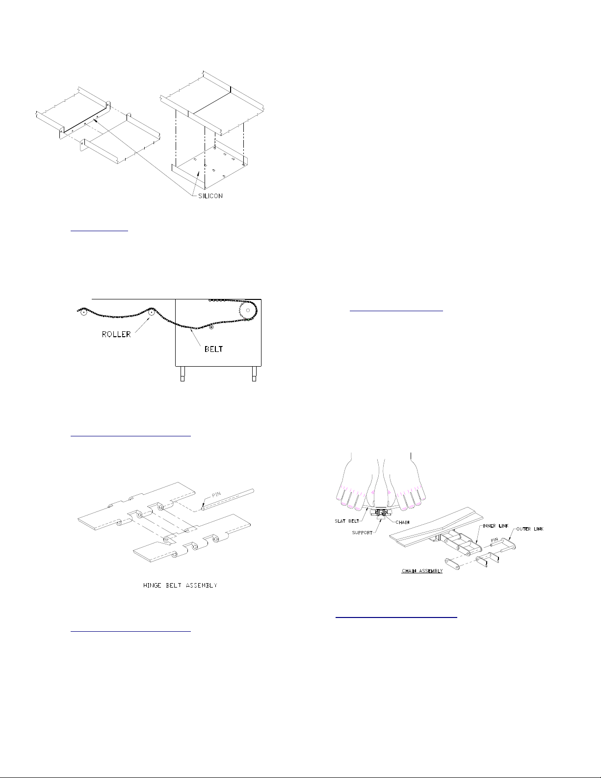
Fig. 3.2
4. Roller Return
On conveyors equipped with a roller return,
feed the belt over all rollers. Slight tension on
the belt should allow the ends to come
together and still leave slack under the slider
bed. [See Fig. 3.3].
Fig. 3.3
5. Belt Assembly - Hinge Type
With hinge type belts, align the ends of the
belt and insert pin. To disassemble, simply
remove the pin. [See Fig. 3.4].
removing the slat from the stainless steel
chain, simply place your thumbs on the
center of the slat with your fingers gripping
the leading edge and “arch” the slat away
from the chain while pulling upward.
When attaching a slat to the chain, bend the
slat upward a fair amount, position the slat
carefully so the small bevels in the slat lugs
align with the extended pins of the chain and
press downward.
The chain must be supported from
underneath with some object such as a
screw driver, handle, or tube.
Service people find that the slat can be
replaced most easily right over the drive
sprocket just before the belt goes down into
the drive/wash tank. Do not HAMMER the
slat onto the chain, it only ruins the slat and
is liable to come off at a later date.
[See Fig. 3.5]
a. Stringing the Slat Belt
To string the belt, loosen the drive
sprocket flange bearing locking collet
which allows the sprocket to run freely.
Install the belt and connect it together
(per fig. 3.4 or 3.5) Center the sprocket
by pushing it against alignment hub and
tighten the locking collet securely. Test
belt alignment by briefly running the
system. Any slippage or realignment
must be immediately addressed to
prevent damage.
Fig. 3.4
6. Belt Assembly - Chain Type
For belts with integral drive chain and
removable individual slats, the links and
slats required for assembly are shipped
loose. To assemble, draw the inner links
together then inserting the outer links, snap
in place. Links can be press-fit together
using channel locks or vise grips. In
Fig. 3.5
7. Belt Assembly - Fabric Type
With fabric type belts, align the ends of the
belt and insert pin. To disassemble, simply
remove the pin. [See Fig. 3.7].
5
Page 6
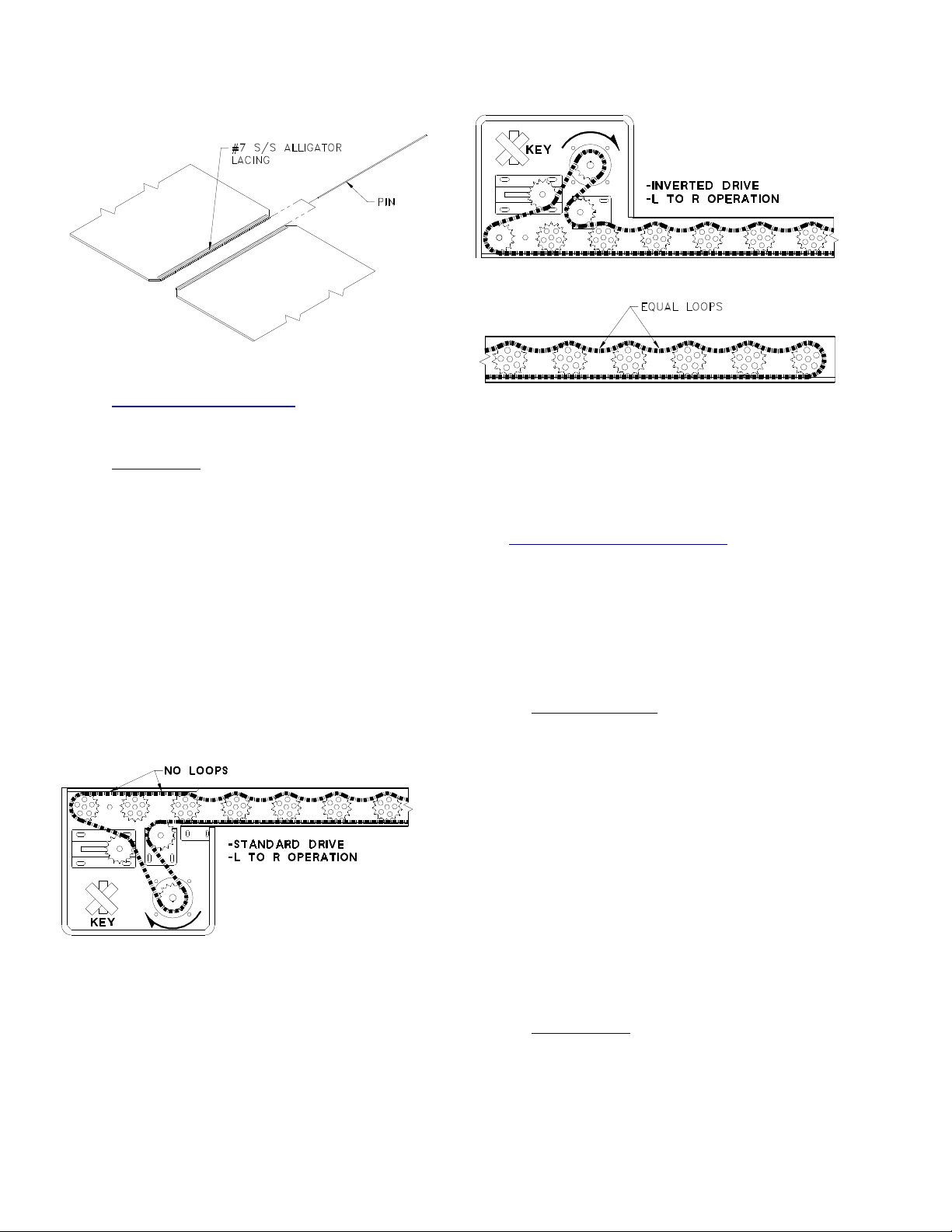
Fig. 3.7
8. Belt Assembly - Cord Type
See welding instruction cut sheet, at end of
manual.
9. Power Roller
Before start-up, the power roller chain must
be realigned. Turn the main sprocket
counter-clockwise (Right to Left operation),
or clockwise (Left to Right operation) until
chain is tight on bottom of sprockets [See
Fig. 3.8 and 3.9]. Loop the chain on top of
the sprockets to take up all excess slack, as
show in Fig. 3.10. For standard drives
(motor on bottom) the chain will not loop for
the first three (3) rollers over the drive
housing [see Fig 3.8]. Be sure to start up the
Power Rollers to verify the correct direction
of the motor, before installing the key. The
motor should turn in the same direction as
mentioned above. The key will be taped to
the inside of the motor housing.
Fig. 3.9
Fig. 3.10
IV
. OPERATION
A control wiring diagram of your specific conveyor
is included at the end of this manual. The
following is a brief, verbal description of the
electrical related features of your unit.
A. Main Conveyor Control Console
Due to the variety of system options some of
the noted controls may not apply to your
system. In the event that the system includes
more than one conveyor, there may be
duplicate sets of controls (one per conveyor).
The controls will be labeled for the appropriate
system.
1. Disconnect Switch
The Disconnect Switch, mounted on the
Conveyor Control Panel, is used only when
servicing the AVTEC conveyor. To remove
power from the conveyor and the
components within the Conveyor Control
Panel, rotate the handle counter-clockwise
so that it is in the off position.
The Disconnect Switch must be in the "Off"
position in order to open or close the front
plate of the Conveyor Control Panel. When
it is in the "Off" position, a lock may be
Fig. 3.8
installed in the handle to prevent the switch
from being turned back on. Turn the handle
to the on position in order to restore power to
the conveyor and the Conveyor Control
Panel.
2. Speed Control
The speed control knob is located on the
main control panel and is clearly labeled.
Turn the knob clockwise to increase the
speed of the conveyor belt. Turn the knob
counter-clockwise to reduce the speed of the
conveyor belt.
6
Page 7

3. Conveyor Stop Switch
Pressing the "Stop" switch will cause all
operations to stop immediately. If the
conveyor is running, it will stop. If the
conveyor is in a wash cycle, the conveyor
will stop and the water solenoid valve and
the detergent pump will shut off.
4. Conveyor Start Switch
The Conveyor Control Panel includes a
"Start" switch. Pressing the "Start" switch will
cause the conveyor belt to begin running.
The conveyor will continue to run until the
"Stop" or “Limit” switch is activated, or until
power is otherwise removed from the
Conveyor Control Panel. Restarting will
restart the wash if in the “Auto” position.
5. Conveyor Wash Switch
The Control center includes a “Rotary Wash
Switch”. There are alternative wash formats.
The term belt is used for either slat or cord
systems, both of which are provided with
wash systems.
The automatic wash feature is
recommended for the most efficient wash
operation however overriding this function
can be made for testing and/or special
requirements.
a.) Belt Wash
If the "Wash" is selected while the
conveyor is running, the water solenoid
valve and the detergent pump will be
activated. The water and detergent will
continue to run as long as the switch is in
this position. The conveyor will continue
to run.
b.) Belt Rinse
If the "Rinse" is selected while the
conveyor is running, the water solenoid
will be energized. The water will continue
to run as long as the switch is in this
position. The detergent pump will not
activate in this position. The conveyor will
continue to run.
c.) Auto-Off
Note: Autowash is provided on all wash
systems shipped after 01, January 2003.
If the “Auto or Off" is selected while the
conveyor is running, the water solenoid
and the detergent pump will be energized
through the P.L.C. program. The
conveyor will continue to run. The
sequence of operation as factory
programmed will activate the rinse, every
third revolution of the belt. The detergent
will be activated every sixth revolution of
the belt. This is considered the
“Automatic” Wash feature, and is most
efficient in utility and detergent use.
6. Low Detergent (optional)
If equipped, the wash/rinse indicator light will
flash until refilled. The light will only
illuminate fully when the Auto wash, rinse, or
wash cycles are engaged, and sufficient
detergent is provided.
7. Limit Switch
The Control center includes a “Rotary Limit
Switch” control. There are alternative belt
run limit switch formats. The term belt is
used for either slat or cord systems, both of
which are provided with limit switches.
a.) On
If the "On" position is selected while the
conveyor is energized, the conveyor will
run continuously until a tray reaches the
terminus limit switch, generally located at
the drive end of the conveyor.
b.) Off
If the "Off" is selected while the conveyor
is energized, an operator must be present
as the conveyor will run continuously
without any limiting stop switch. The
primary function of this feature is to
eliminate nuisance tripping during peak
operations and for overriding trouble
situations.
c.) Auto Index (if applicable)
If "Auto" is selected on the limit switch
while the conveyor is energized, equipped
with a drop-off area limit switch, the belt
will only run for a timed period after the
drop-off area limit switch is triggered.
This maximizes accumulation capacity
without requiring operator presence.
Factory programmed through the P.L.C.
the conveyor will run only for
approximately eight (8) seconds after the
limit switch is triggered. Field adjustment
of the time can only be made through
replacement or reprogramming of the
P.L.C.
If the conveyor dose not have Auto Index,
the switch on the control panel will only
be a two position switch, and the light
above the switch will not turn on (dummy
7
Page 8
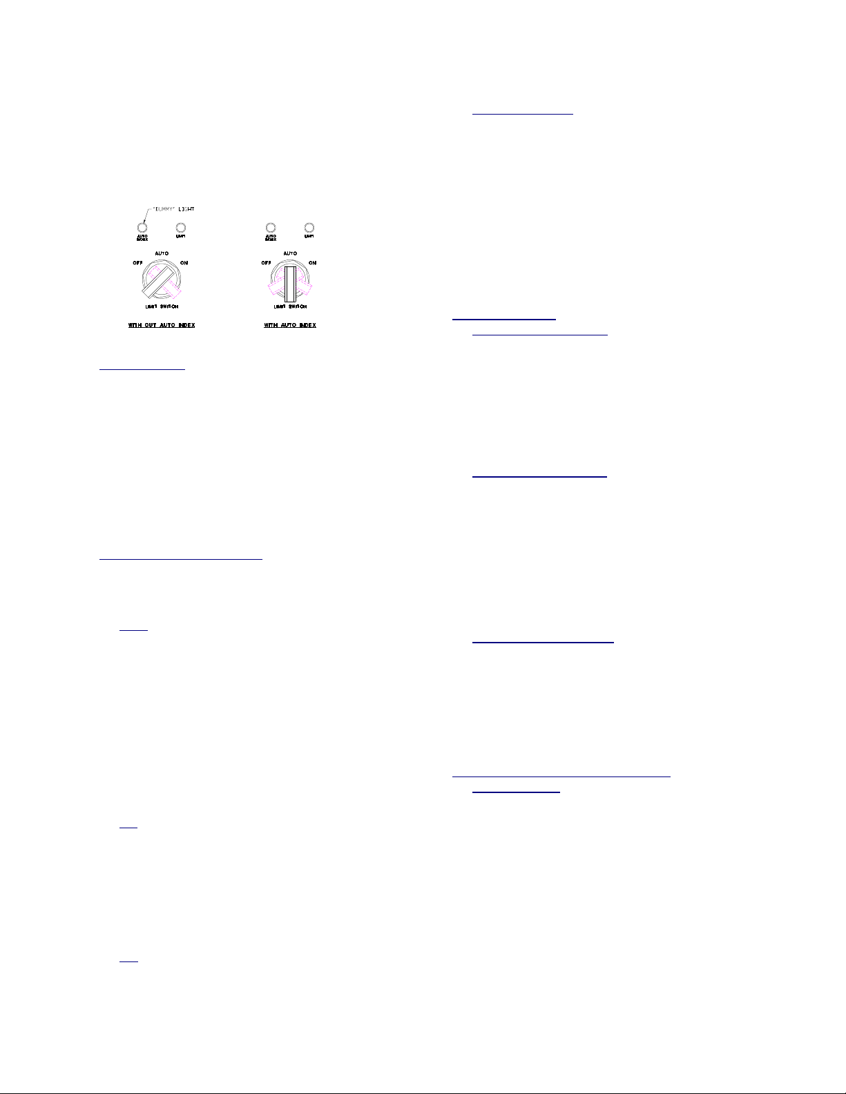
light). This makes it possible to add Auto
Index in the future, at a minimal added
cost. If the conveyor has Auto index, the
switch will be a three position, enabling
the user to select Auto. When this is done
the light will turn on. [see Fig 4.7]
10. Visual Indicators
There are numerous indicator lights located
adjacent to their respective controls. These
illuminate to indicate that various equipment
and/or operations are energized. They are
labeled accordingly. A flashing light
generally indicates a momentary function is
energized, or customer actions are
required.
There may also be “dummy” lights on the
control panel, that may be used in future
upgrades. These lights do not light up.
Fig. 4.7
8. Power Rollers
The Control center includes a start-stop
control for the power roller conveyor. There
is no adjustment required for the speed and
wash does not apply. Limit switches are not
required for these systems. The rollers are
powered but, include a slip-type drive
allowing the operator to stop items on the
rollers without damage or injury to the
equipment or operator.
9. Auto Plate Rinse (optional)
The Control center includes a “Rotary APR
Switch” for the plate rinse sprayers, if
provided. The functions include;
a.) Auto
If the "Auto" is selected with the system
energized, the water solenoid will be
opened only upon activation of the
electric photo-eye switch. The spray head
shut-off must be in the open or on
position. The timed cycle in the “auto”
position opens the solenoid for
approximately ten (10) seconds. Field
adjustment of this time can only be made
through replacement or reprogramming
of the P.L.C..
b.) On
If the "On" is selected the water solenoid
will be continuously open. The water will
continue to run as long as the switch is in
this position and the manual shut-off is in
the open or on position. Individual shutoff can be manually achieved by closing
the shut-off located on the spray head.
c.) Off
If the "Off" is selected the water solenoid
will not be energized and the water will
not flow.
B. Remote Controls (Optional)
1. Conveyor Start Switch
A conveyor Start switch may be located
remote on a separate control panel. There
may be more than one (1) Start switch.
Pressing any Start switch will cause the
conveyor belt to go into motion unless the
system is not energized or a limit switch is
deactivating the belt motion.
2. Conveyor Stop Switch
A conveyor Stop switch may be located
remote on a separate control panel. There
may be more than one (1) Stop switch.
Pressing any one of the Stop switches will
cause the conveyor to stop immediately.
Some conveyors are equipped with a large,
red, mushroom-shaped Stop switch that is
easier for users to operate, “hands-free” or
denoted for an “emergency stop”.
3. Momentary Run Switch
Some conveyors may be equipped with a
momentary contact conveyor run switch,
remote of the main conveyor control panel. If
the conveyor is off, pressing the black
Momentary Switch will cause the conveyor to
run for as long as the switch is held in, then
stop as soon as it is released.
C. Limit and Safety Switches (optional)
1. Limit Switches
A limit switch may be provided with the
conveyor. When activated (ON), the “EndType” limit switch will momentarily stop the
conveyor belt, when activated. A momentarytype switch allows the conveyor belt to
resume running as soon as the obstruction is
removed. This may be used on any type of
conveyor and may be located at the end of a
clean dish-table.
When set to (AUTO) and equipped with a
drop-off area “Auto-Indexing Type” limit
switch, the conveyor belt will advance the belt
for a brief time or distance, to maximize
accumulation. Refer to Auto-Indexing.
8
Page 9
a. Photoelectric Sensor
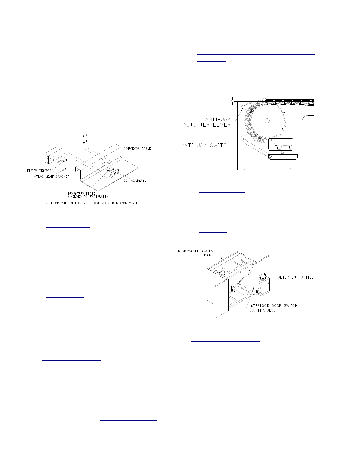
The photoelectric, beam type switch uses a
polarized, reflected beam of light to
determine when an object has reached the
end of the conveyor. When the beam of
light is interrupted, the conveyor stops.
When the obstruction is removed, the
conveyor continues. To service this unit,
turn off conveyor and access the switch by
removing the screws (or nuts) and switch
housing. Reverse steps to re-assemble.
[See Fig. 4.1]
Fig. 4.1
b. Arm Switch Type (optional)
A flexible, movable arm actuator attached
to an electrical switch may be mounted in
the backsplash of the conveyor bed.
When an object moves the arm, the
conveyor stops momentarily. When the
object is removed, the conveyor continues
to run. This type of switch is only used
when a beam type switch cannot sense all
items entering the limit area.
restart until the anti-jam switch returns to its
normal running position AND the Start switch
is pressed. This is a NON-Momentary safety
device that should not be overridden or
disconnected. The obstruction can then be
removed or will fall into the scrap basket
below.
Fig. 4.9
3. Drive Door Safety (post 01/01/03)
The conveyor may be equipped with a drive
door safety switch. When a drive access
door is opened, the conveyor will stop
operation. The conveyor will not restart until
the door is fully closed AND the Start switch
is pressed. This is a NON-Momentary safety
device that should not be overridden or
disconnected. [See Fig. 4.8]
c. Pressure Type
A flat plate located at the end of the belt is
attached to an electrical switch mounted at
the end of the conveyor bed on the tank.
When an object moves the plate, the
conveyor stops momentarily. When the
object is removed, the conveyor continues
to run.
2. Anti-Jam Safety Switch (post 01/01/03)
The conveyor may be equipped with a
retractable anti-jam switch, standard on CI**
and CB** models only. The switch is mounted
at the drive end, just below the conveyor
surface, where the belt enters into the drive.
[See Fig. 4.9] When an object becomes
wedged between the belt and the table, the
switch pivots and electrically causes the
conveyor belt to stop. The conveyor will not
Fig. 4.8
D. Motor Control Adjustments
Your Avtec motorized conveyor system is
provided with a KB Electronics adjustable
frequency drive control. Refer to PentaPower
KB Electronics motor control booklet or contact
Avtec Ind..
E. Water Usage
All of the following information is with the
mixing valves half open, which is the factory
setting, and what Avtec recommends. The
water usage is only while washing, or rinsing.
9
Page 10
1. Slat Belt Conveyors
The Slat type conveyor wash housings will
use 4gpm.
2. Cordveyor
Cordveyors use 2.625 gpm.
3. Auto Plate Rinse
The APR’s use 2.5 gpm, per (1) APR, fully
open.
V. MAINTENANCE
A. Cleaning
It is important that the AVTEC conveyor is kept
clean in order to avoid unsanitary conditions. It
has been designed with ease of cleaning in
mind. It is recommended that the electrical
power to the conveyor be turned off or
disconnected while being cleaned. NOTE: DO
NOT use steel wool or any other abrasive pad
on the conveyor belt, cord, roller or stainless
steel surfaces.
DO NOT spray the conveyor controls directly
with a hose.
1. Drip Pan - for Slat Type Belt
Standard drip pans are actually UHMW lined
belt return guides that are self-cleaning by the
friction of the belt as it operates. At the initial
time of installation these pans should be
wiped for construction debris prior to initial
start-up.
Fig. 5.2
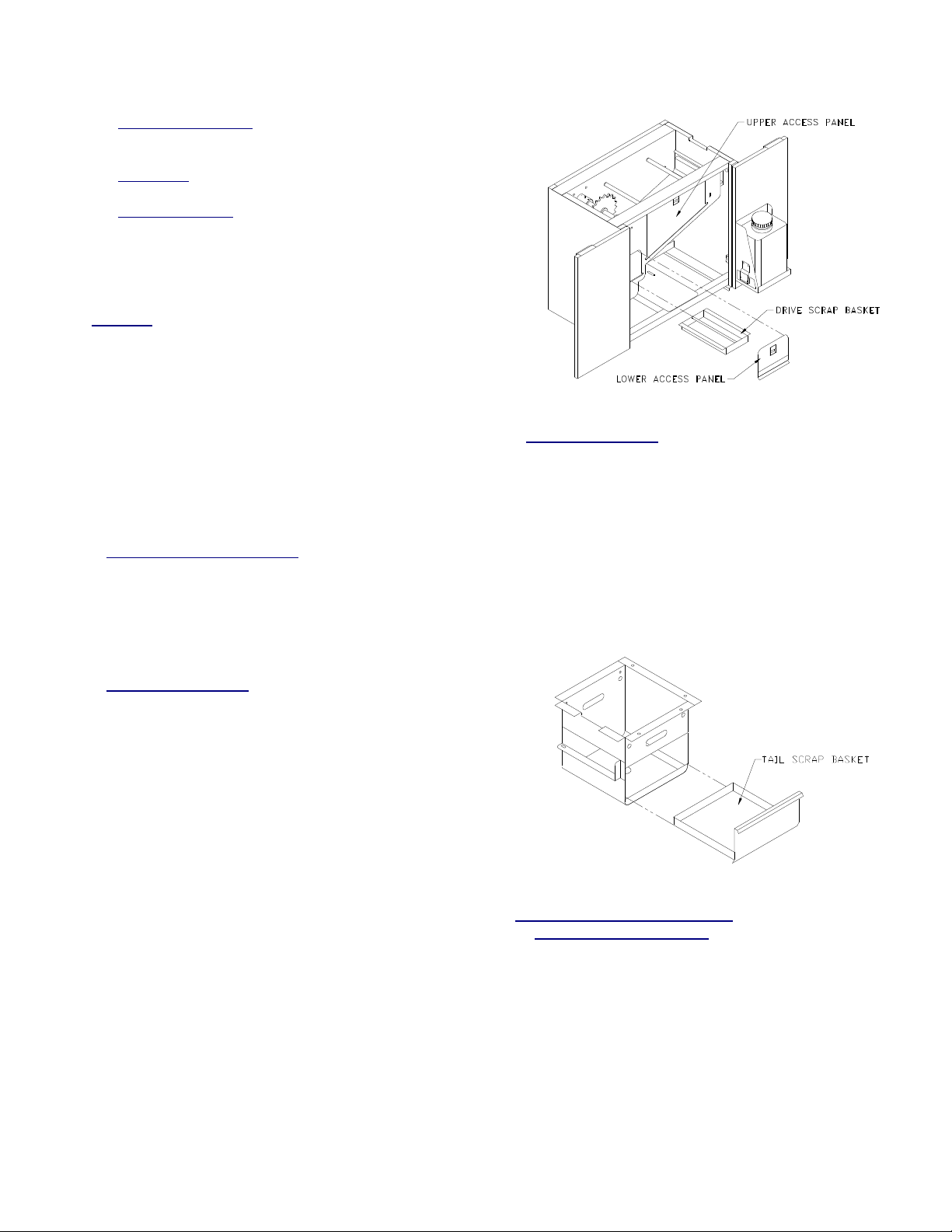
4. Scrap Basket (Tail)
Conveyors equipped with wash have a scrap
basket to prevent drain blockage at the tail
end. This scrap basket requires periodic
removal to empty its contents. The basket is
located at the base of the tail end sprocket
support bracket. [See fig. 5.3].
To remove:
1. Turn off conveyor
2. Simply slide scrap basket out of chute,
clean it and the sump area.
3. Reverse steps to install.
2. Scrap Basket (Tank)
Conveyors equipped with the belts or cords
have a scrap basket to catch debris and
prevent drain blockage. This scrap basket
requires periodic removal to empty its
contents. The basket is located internally
within the wash tank. [See fig. 5.2].
To remove:
1. Turn off the conveyor
2. Remove the lower lift-out access panel
3. Simply slide the scrap basket out of tank,
clean it and the sump area.
4. Reverse steps to install.
Fig. 5.3
B. Detergent Pump Housing/Bottle
1. Detergent Pump Housing
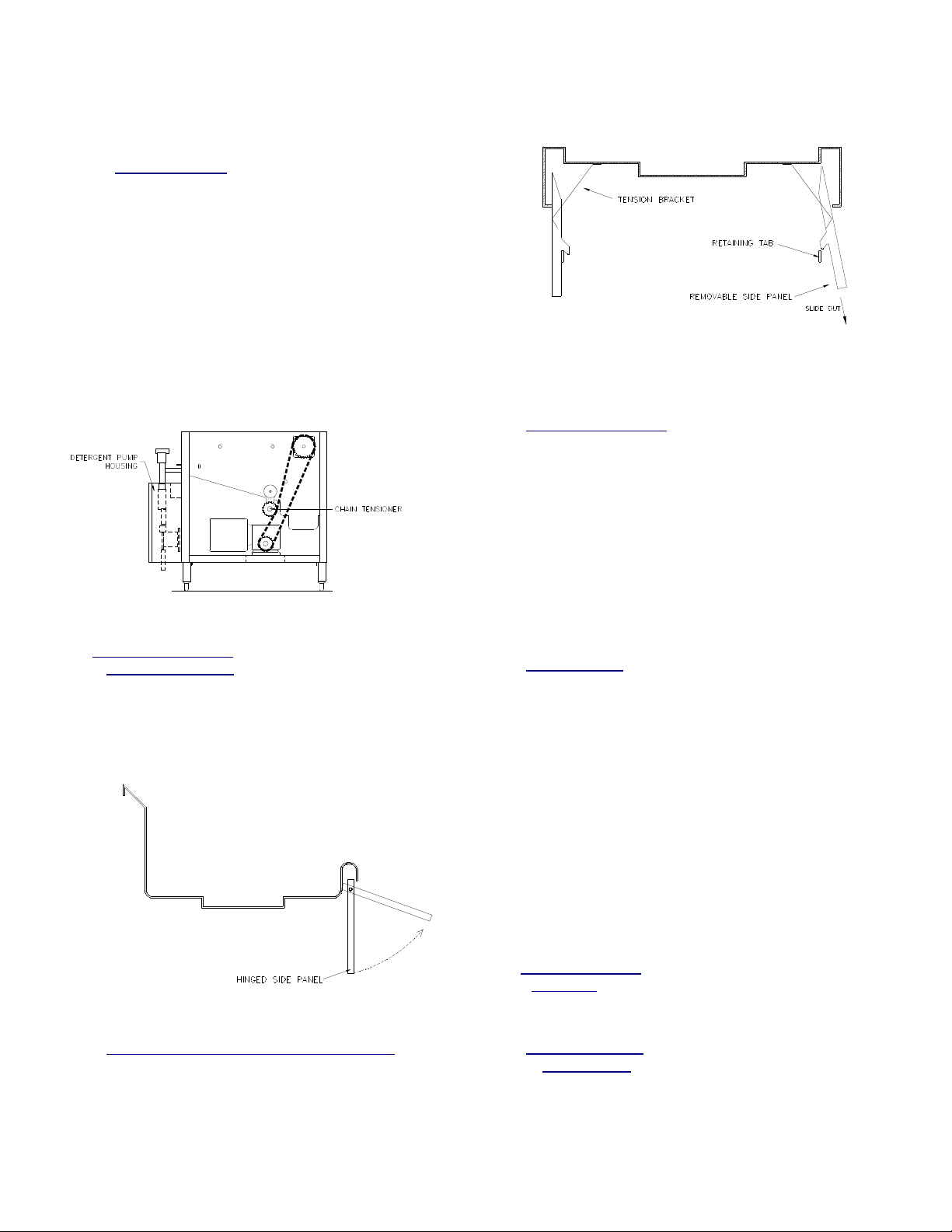
The detergent pump housing is typically
located on either side of the drive housing
[See fig. 5.4]. To prime pump, the fitting on
the discharge side of the pump must be
removed to relieve any pressure. The line
must be submerged into a liquid solution and
the conveyor started with the Belt Wash
switch in the wash position. Run the system
until fluid is seen flowing through pump. Set
stroke of pump with adjustment knob located
on pump (factory setting is #2). Use a
10
Page 11
detergent with a disinfecting agent. (WEAR
PROTECTIVE EYE GEAR).
2. Detergent Bottle
The detergent bottle, if supplied, is mounted
on one of the drive doors (see Fig 4.8) with a
5 ft tube and foot valve supplied for insertion
into your detergent bottle (tank).
AVTEC recommends EVAC Detergent for
use in the conveyor system. It generally is
effective in water at temperature between
40ºF and 140ºF (Must be minimum 70ºF if
sanitization is required. Note: A lubricating
type detergent is not required for proper belt
operation).
C. Access for Servicing
1. Hinged Side Panel
For most conveyors, access to the lower
section requires simply swinging the panels
up. The panels remain in the up position until
lowered.
Fig. 5.4
[See fig. 5.5A]
direction. [See fig. 5.5B]
Fig. 5.5B
3. Upper Access Panel
Conveyors equipped with the optional belt
wash/rinse feature, have a lift out access
panel on the side of the tank to facilitate
access to the sprocket, shaft and plumbing.
Turn off all power to the conveyor before
removing the access panel. [See fig. 5.2].
This is where access to the locking sprocket
collet is obtained. Refer to installation
requirements for sprocket alignment
requirements.
4. Drive Housing
The standard housing is equipped with
double hinged, double pan doors for access
to the upper and lower access panels [See
fig. 4.8]. The conveyor must be turned off
before any maintenance or cleaning is
performed.
A back access panel, that is removable with
tools, for access to sprockets, chain, motor
and gear box. The conveyor must be turned
off before this panel is removed.
An interlock switch will prevent the conveyor
from running when a hinged panel is opened.
[See fig. 4.8]
D. Routine Servicing
1. Gear Box
Fig. 5.5A
2. Removable Side Panel (Tray Make-up Only)
Access to the lower section requires
removing the side panels. To remove the side
panel, lift up the panel past the retaining tab,
and slide out in downward and outward
The gearbox is lubricated for life; overhaul is
required to change oil.
2. Visual Inspection
a. Slat type belt
Visually inspect every month for wear,
chips, scratches, cracks, signs of
misalignment and excessive slack in the
11
Page 12
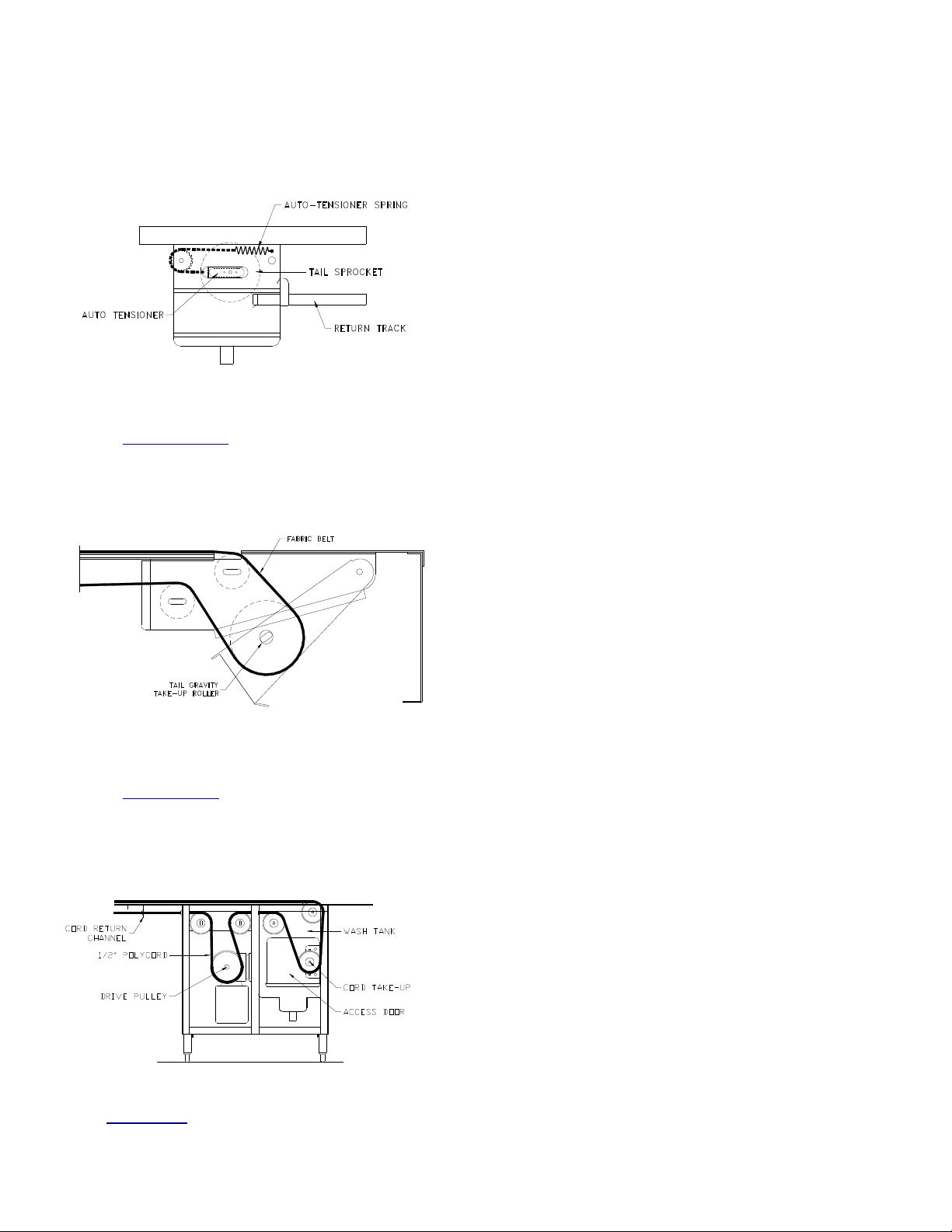
belt. The tail take-up [see fig 5.6] should
automatically take up any excess slack.
• Lubricate the Intermediate Drive Chain
[which runs from the gearbox to the belt
drive sprocket] after one [1] month of
operation.
• Lubricate every four [4] months of
operation thereafter.
• Recommended Lubricant:
Roller Chain Lubricant
McMaster-Carr No. 6159 K11 or
equivalent.
Fig 5.6
b. Fabric type belt
Visually inspect every month for wear,
chips, scratches, cracks or signs of
misalignment. All fabric belts have a autotake up feature [see fig. 5.7].
Fig. 5.7
c. Cord type belt
Visually inspect every month for wear,
cracks or signs of cutting or twisting. The
Cord take-up, located in the drive [see fig
5.8], can be accessed by removing the
wash housing access door.
Fig. 5.8
3. Drive Chain
12
Page 13

VI. PARTS LIST
ITEM NO. AVTEC PART NO. DESCRIPTION
1 HD BLT0302 10" wide Interlocking Assembly (Grey)
ITEM NO. AVTEC PART NO. DESCRIPTION
1 HD CHN0307 #60 side flexing water proof chain
2 HD SLT0301 10” wide slat w/pins and rollers (blue)
3 HD SLT0303 10” wide slat w/pins and rollers (black)
4 HD SLT0302 10” wide slat w/pins and rollers (gray)
ITEM NO. AVTEC PART NO. DESCRIPTION
1 HD CBL0301 1/2” Hyfen polyester fiber core polyurethane can-cable
2 HD BLT0309 5/16” Orange-Go polyurethane cord
ITEM NO. AVTEC PART NO. DESCRIPTION
1 HD BLT0310 10.75” wide 2-ply (blue #22-84) [Slim-Line Model]
2 HD BLT0305 10” wide 2-ply (blue #22-84) [K-Line model]
3 HD BLT0308 10” wide 2-ply (white) [Customer Spec.]
ITEM NO. AVTEC PART NO. DESCRIPTION
1 HD ROL0308 1.9” stainless steel roller
ITEM NO. AVTEC PART NO. DESCRIPTION
1 HD ROL0404 7.958”L x 1.9” o.d. grey roller (for 24” BFR in turn)
2 HD ROL0323 23.875”L x 1.9” o.d. grey straight roller
3 HD ROL0401 3.375”L x 1.9” o.d. grey straight roller
4 RP SHT0402 3.5” x 7/16” aluminum hex. shaft drilled/tapped/anodized
5 HD SHT0301 24” x 7/16” aluminum hex. shaft drilled/tapped/anodized
6 HD ROL0302 10.75" grey PVC roller w/shaft
ITEM NO. AVTEC PART NO. DESCRIPTION
1 HD WHL0301 Grey with 5/16” bore; standard for all applications
2 N/A 5/8” o.d. white Delrin roller standoff (custom per app.)
A. BELT (CI SERIES)
B. BELT (CB SERIES)
C. CORD (CC SERIES)
D. FABRIC BELT (CF SERIES)
E. POWER ROLLERS (CP SERIES)
F. GRAVITY ROLLERS (CR SERIES)
G. SKATE WHEELS (CS SERIES)
13
Page 14

H. WEAR STRIP
ITEM NO. AVTEC PART NO. DESCRIPTION
1 PL GID0301 Snap on rail guide for 1” tubing; CB model up-racking
benches only. (consult with engineering prior to order)
2 PL GID0302 Modified T-guide rail; roll formed at factory per job.
(consult with engineering prior to placing order)
3 PL STR0302 Beveled profile strip; CB models only
4 PL TPE0301 10.125” return track liner
5 PL TPE0302 Return track liner corner piece; must be cut at factory
6 PL TPE0303 Conveyor bed liner; CI models only
7 PL GID0303 #50 Chain guide; #7 UHMW profile (CP only!)
I. BELT SPROCKET (CI SERIES)
ITEM NO. AVTEC PART NO. DESCRIPTION
1 HD SPK0312 UHMW sprocket (drive)
2 HD SPK0313 UHMW sprocket (tail)
J. BELT SPROCKET (CB SERIES)
ITEM NO. AVTEC PART NO. DESCRIPTION
1 HD SPK0304 60A25 s/s sprocket (drive)
2 HD SPK0302 60B25 UHMW sprocket (tail)
K. BELT PULLEYS (CC SERIES)
ITEM NO. AVTEC PART NO. DESCRIPTION
1 HD PUL0302 4.4” dia. Idler pulley (requires machining at factory)
2 HD PUL0301 4.4” dia. Idler pulley for wash tank
(requires machining at factory)
3 HD PUL0303 Drive sheave; nylon coated
L. BELT PULLEYS (CF SERIES)
ITEM NO. AVTEC PART NO. DESCRIPTION
1 HD ROL0304 Hi output powered drive roller (Slim-line)
2 PL PUL0302 Tail roller with bearings (Slim-line)
3 PL PUL0303 6.5” dia. Steel pulley; crowned w/neoprene lagging
(must be ordered as an assy. with drive sprocket)
4 HD ROL0314 13.38”L Snub drive roller (K-Line)
5 HD ROL0311 11”L Snub tail roller (K-Line)
6 HD ROL0310 14.5”L Idler roller (K-Line & S-line)
7 HD ROL0303 11.88” Snub drive roller (S-line)
8 HD ROL0305 11.5” Snub tail roller (S-line)
14
Page 15

M. INTERMEDIATE DRIVE (CI, CB SERIES)
ITEM NO. AVTEC PART NO. DESCRIPTION
1 PB CPL0317 Transtorque shaft coupler (couples sprocket to shaft)
2 HD SPK0305 Shaft sprocket
3 HD SPK0306 Reducer Sprocket
4 HD CHN0304 #50 waterproof roller chain
5 HD LNK0304 #50 waterproof connection link
6 HD LNK0309 #50 waterproof half link
N. BEARINGS (Wash Tank Drive) (CI, CB, CF SERIES)
ITEM NO. AVTEC PART NO. DESCRIPTION
1 HD BRG0304 Flanged bearing with locking collet
2 HD BRG0305 Flanged bearing adapter (1”)
3 HD BLK0304 3/4” bore pillow block (CF only)
O. DRIVE COMPONENTS (CI, CB SERIES)
ITEM NO. AVTEC PART NO. DESCRIPTION
1 EL MTR0301 1/2 HP 3-phase motor
2 EL MTR0307 3/4 HP 3-phase motor
3 HD RED0308 60:1 reducer; shaft is on right as viewed from motor
4 HD RED0311 60:1 reducer; shaft is on left as viewed from motor
5 HD RED0305 80:1 reducer; shaft is on left as viewed from motor
6 HD RED0306 80:1 reducer; shaft is on right as viewed from motor
7 HD RED0309 100:1 reducer; shaft is on right as viewed from motor
8 HD RED0310 100:1 reducer; shaft is on left as viewed from motor
P. DRIVE COMPONENTS (CC SERIES)
ITEM NO. AVTEC PART NO. DESCRIPTION
1 EL MTR0301 1/2 HP 3-phase motor
2 EL MTR0307 3/4 HP 3-phase motor
3 HD RED0307 Dual shaft reducer
Q. DRIVE COMPONENTS (CF SERIES)
ITEM NO. AVTEC PART NO. DESCRIPTION
1 EL MTR0301 1/2 HP 3-phase motor
2 HD RED0305 80:1 reducer; shaft is on left as viewed from motor
3 HD RED0306 80:1 reducer; shaft is on right as viewed from motor
4 HD SPK0306 Reducer Sprocket
5 HD SPK0316 Shaft sprocket
6 HD CHN0304 #50 waterproof roller chain
7 HD LNK0304 #50 waterproof connection link
8 HD LNK0309 #50 waterproof half link
15
Page 16

R. DRIVE COMPONENTS (CP SERIES)
ITEM NO. AVTEC PART NO. DESCRIPTION
1 EL MTR0302 1/2 HP parallel gear motor
2 HD SPK0318 Molded sprocket (roller shaft)
3 HD SPK0324 Motor sprocket
4 HD CHN0304 #50 waterproof roller chain
5 HD LNK0304 #50 waterproof connection link
6 HD BRG0312 Molded delrin shaft bearing (press into s/s side rails)
7 HD IDL0301 Ball bearing idler sprocket
S. CONTROL PANEL COMPONENTS (All models)
ITEM NO. AVTEC PART NO. DESCRIPTION
1 EL DIS0303 Disconnect switch
2 EL DIS0304 Disconnect handle rod
3 EL DIS0305 Disconnect handle
4 EL SWT0333 Power switch (Slim-line only!)
5 EL SWT0312 30mm push button (start/stop)
6 EL SWT0310 20mm push button
(Old style PLC controls & Aux. Start/Stop Stations)
7 EL BLK0319 Normally closed contact block
8 EL SWT0315 2-position selector switch
9 EL SWT0313 3-position selector switch
10 EL RLY0314 Power supply/relay (for use with beam switches)
11 EL RLY0326 DPDT relay; 24VDC coil
12 EL RLY0327 DPDT relay base
13 EL TPE0301 Relay; 3PDT; 24VDC coil
14 EL SWT0342 Relay base
15 EL LGT0305 1/2" red indicator light
16 EL LGT0306 5/16” red neon indicator light
17 HD CNT0304 Variable frequency drive (1/2 HP)
18 EL INV0301 Variable frequency drive (3/4+ HP)
19 EL PLC0303 Allen Bradley PLC (20/12 I/O)
(Discontinued, consult factory)
20 EL PLC0302 Koyo D0-05DR PLC
21 EL PLC0304 Koyo D0-06DR PLC
22 EL PLC0305 Allen Bradley PLC (10/6 I/O)
(Discontinued, consult factory)
23 EL RLY0328 Mag. Starter (CP only!)
25 HD KNB0303 Speed pot knob
26 HD SEA0303 Speed pot cupseal
27 FA WSH0310 Speed pot finishing washer
28 EL SUP0301 Idec 7.5W 24VDC switching power supply
16
Page 17

T. DETERGENT UNIT / WASH / APR (All models)
ITEM NO. AVTEC PART NO. DESCRIPTION
1 PB SOL0301 Wash solenoid
2 PB VLV0320 APR solenoid
3 HD PMP0302 Detergent pump
4 PB VLV0315 Mixing valve (universal application)
5 PB HSE0302 12”L x 1/2” IPS s/s flex line
6 PL HSE0303 20”L x 1/2" IPS s/s flex line
7 HD STN0302 1/2" line strainer
8 HD TNK0302 2 gal. detergent tank
9 PB VLV0318 1/2" vacuum breaker
10 PB VLV0347 1/2” sweat spring check valve
11 AS NZL0308 APR shower head
U. SENSORS (All models)
ITEM NO. AVTEC PART NO. DESCRIPTION
1 EL SEN0301 Thru beam sensor
2 EL SEN0303 Diffuse reflection; short range
3 EL SEN0304 Diffuse reflection; long range
4 EL SEN0302 Low detergent sensor
5 EL SWT0331 Anti-jam micro-switch
6 EL SWT0332 Door ajar micro-switch
17
Page 18
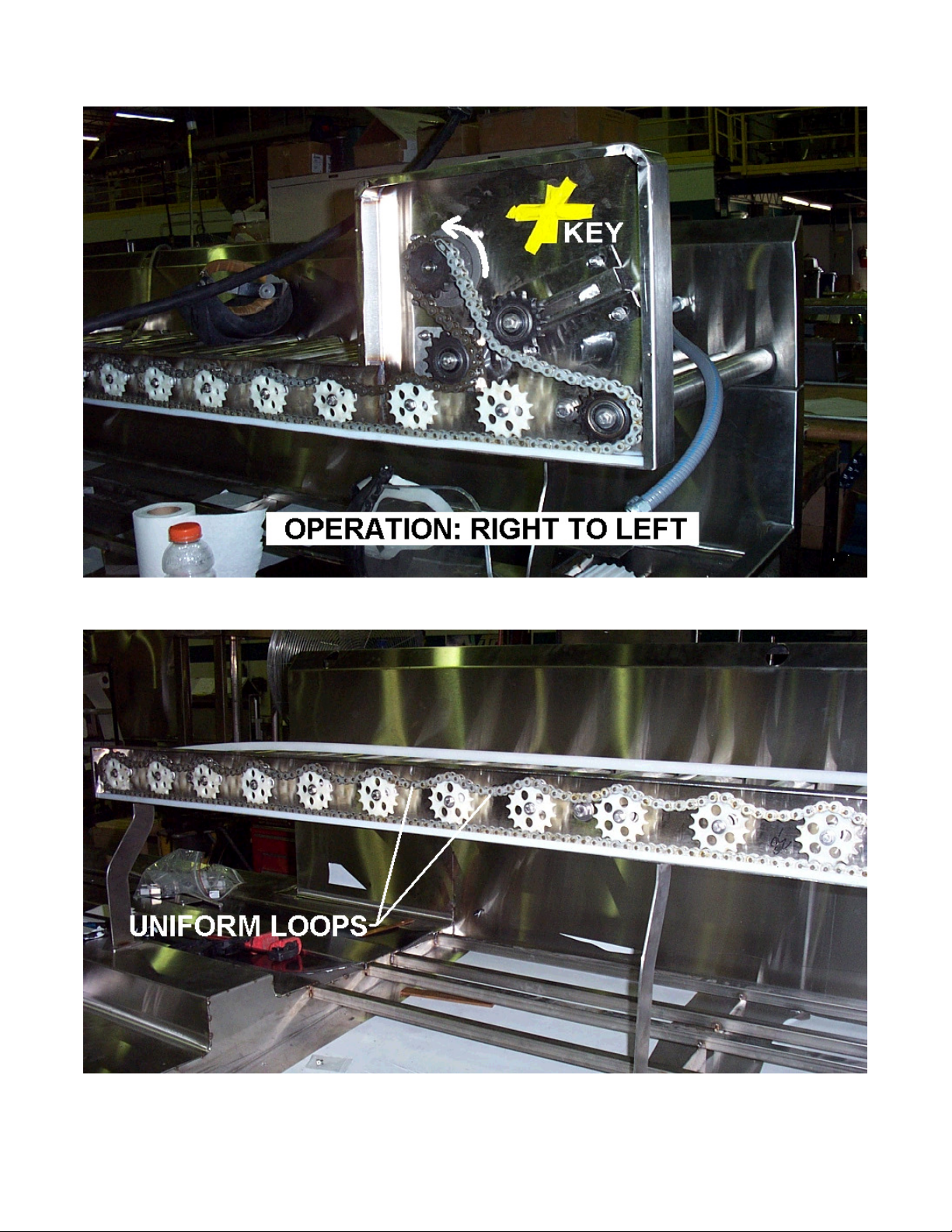
Fig. 15.1
Fig. 15.2
18
Page 19

-WARRANTY-
AVTEC INDUSTRIES INC. warrants to the original purchaser for use of our products, that any part
thereof which proves to be defective in material or workmanship under normal use within one year
from date of installation, will be replaced free of charge, labor to replace such part is warranted for
one year from installation. All warranty labor to be performed during regular working hours, with no
overtime premium.
All Warranty service must be authorized by the factory and be performed by AVTEC’s authorized
service personnel.
This Warranty is limited to the United States and Canada.
This Warranty does not apply to any damage resulting from shipping, improper installation,
accident, unauthorized alteration, local codes not previously brought to the attention of AVTEC,
misuse, or abuse; and does not cover loss of food, other products or damage to equipment or
property resulting from mechanical or electrical failure.
AVTEC neither makes nor assumes and does not authorize any other person to assume any other
obligation or liability in connection with its products other than that covered in this Warranty.
FOR THE NAME AND LOCATION OF THE NEAREST
AVTEC SERVICE AGENCY, CALL OR WRITE TO:
AVTEC INDUSTRIES INC.
525 S. Coldwater Rd.
Weidman, Michigan 48893
800/621-8560
LOCAL SERVICE AGENCY
OMANUAL_CM-12/06
19
 Loading...